EP2489385A1 - Auto-injector - Google Patents
Auto-injector Download PDFInfo
- Publication number
- EP2489385A1 EP2489385A1 EP11155040A EP11155040A EP2489385A1 EP 2489385 A1 EP2489385 A1 EP 2489385A1 EP 11155040 A EP11155040 A EP 11155040A EP 11155040 A EP11155040 A EP 11155040A EP 2489385 A1 EP2489385 A1 EP 2489385A1
- Authority
- EP
- European Patent Office
- Prior art keywords
- carrier
- chassis
- case
- auto
- injector
- Prior art date
- Legal status (The legal status is an assumption and is not a legal conclusion. Google has not performed a legal analysis and makes no representation as to the accuracy of the status listed.)
- Ceased
Links
Images


Classifications
-
- A—HUMAN NECESSITIES
- A61—MEDICAL OR VETERINARY SCIENCE; HYGIENE
- A61M—DEVICES FOR INTRODUCING MEDIA INTO, OR ONTO, THE BODY; DEVICES FOR TRANSDUCING BODY MEDIA OR FOR TAKING MEDIA FROM THE BODY; DEVICES FOR PRODUCING OR ENDING SLEEP OR STUPOR
- A61M5/00—Devices for bringing media into the body in a subcutaneous, intra-vascular or intramuscular way; Accessories therefor, e.g. filling or cleaning devices, arm-rests
- A61M5/178—Syringes
- A61M5/31—Details
- A61M5/32—Needles; Details of needles pertaining to their connection with syringe or hub; Accessories for bringing the needle into, or holding the needle on, the body; Devices for protection of needles
-
- A—HUMAN NECESSITIES
- A61—MEDICAL OR VETERINARY SCIENCE; HYGIENE
- A61M—DEVICES FOR INTRODUCING MEDIA INTO, OR ONTO, THE BODY; DEVICES FOR TRANSDUCING BODY MEDIA OR FOR TAKING MEDIA FROM THE BODY; DEVICES FOR PRODUCING OR ENDING SLEEP OR STUPOR
- A61M5/00—Devices for bringing media into the body in a subcutaneous, intra-vascular or intramuscular way; Accessories therefor, e.g. filling or cleaning devices, arm-rests
- A61M5/46—Devices for bringing media into the body in a subcutaneous, intra-vascular or intramuscular way; Accessories therefor, e.g. filling or cleaning devices, arm-rests having means for controlling depth of insertion
-
- A—HUMAN NECESSITIES
- A61—MEDICAL OR VETERINARY SCIENCE; HYGIENE
- A61M—DEVICES FOR INTRODUCING MEDIA INTO, OR ONTO, THE BODY; DEVICES FOR TRANSDUCING BODY MEDIA OR FOR TAKING MEDIA FROM THE BODY; DEVICES FOR PRODUCING OR ENDING SLEEP OR STUPOR
- A61M5/00—Devices for bringing media into the body in a subcutaneous, intra-vascular or intramuscular way; Accessories therefor, e.g. filling or cleaning devices, arm-rests
- A61M5/178—Syringes
- A61M5/20—Automatic syringes, e.g. with automatically actuated piston rod, with automatic needle injection, filling automatically
- A61M5/2033—Spring-loaded one-shot injectors with or without automatic needle insertion
-
- A—HUMAN NECESSITIES
- A61—MEDICAL OR VETERINARY SCIENCE; HYGIENE
- A61M—DEVICES FOR INTRODUCING MEDIA INTO, OR ONTO, THE BODY; DEVICES FOR TRANSDUCING BODY MEDIA OR FOR TAKING MEDIA FROM THE BODY; DEVICES FOR PRODUCING OR ENDING SLEEP OR STUPOR
- A61M5/00—Devices for bringing media into the body in a subcutaneous, intra-vascular or intramuscular way; Accessories therefor, e.g. filling or cleaning devices, arm-rests
- A61M5/178—Syringes
- A61M5/20—Automatic syringes, e.g. with automatically actuated piston rod, with automatic needle injection, filling automatically
-
- A—HUMAN NECESSITIES
- A61—MEDICAL OR VETERINARY SCIENCE; HYGIENE
- A61M—DEVICES FOR INTRODUCING MEDIA INTO, OR ONTO, THE BODY; DEVICES FOR TRANSDUCING BODY MEDIA OR FOR TAKING MEDIA FROM THE BODY; DEVICES FOR PRODUCING OR ENDING SLEEP OR STUPOR
- A61M5/00—Devices for bringing media into the body in a subcutaneous, intra-vascular or intramuscular way; Accessories therefor, e.g. filling or cleaning devices, arm-rests
- A61M5/178—Syringes
- A61M5/31—Details
- A61M5/315—Pistons; Piston-rods; Guiding, blocking or restricting the movement of the rod or piston; Appliances on the rod for facilitating dosing ; Dosing mechanisms
- A61M5/31565—Administration mechanisms, i.e. constructional features, modes of administering a dose
- A61M5/31566—Means improving security or handling thereof
- A61M5/3157—Means providing feedback signals when administration is completed
-
- A—HUMAN NECESSITIES
- A61—MEDICAL OR VETERINARY SCIENCE; HYGIENE
- A61M—DEVICES FOR INTRODUCING MEDIA INTO, OR ONTO, THE BODY; DEVICES FOR TRANSDUCING BODY MEDIA OR FOR TAKING MEDIA FROM THE BODY; DEVICES FOR PRODUCING OR ENDING SLEEP OR STUPOR
- A61M5/00—Devices for bringing media into the body in a subcutaneous, intra-vascular or intramuscular way; Accessories therefor, e.g. filling or cleaning devices, arm-rests
- A61M5/178—Syringes
- A61M5/31—Details
- A61M5/32—Needles; Details of needles pertaining to their connection with syringe or hub; Accessories for bringing the needle into, or holding the needle on, the body; Devices for protection of needles
- A61M5/3205—Apparatus for removing or disposing of used needles or syringes, e.g. containers; Means for protection against accidental injuries from used needles
- A61M5/321—Means for protection against accidental injuries by used needles
- A61M5/3243—Means for protection against accidental injuries by used needles being axially-extensible, e.g. protective sleeves coaxially slidable on the syringe barrel
- A61M5/326—Fully automatic sleeve extension, i.e. in which triggering of the sleeve does not require a deliberate action by the user
-
- A—HUMAN NECESSITIES
- A61—MEDICAL OR VETERINARY SCIENCE; HYGIENE
- A61M—DEVICES FOR INTRODUCING MEDIA INTO, OR ONTO, THE BODY; DEVICES FOR TRANSDUCING BODY MEDIA OR FOR TAKING MEDIA FROM THE BODY; DEVICES FOR PRODUCING OR ENDING SLEEP OR STUPOR
- A61M5/00—Devices for bringing media into the body in a subcutaneous, intra-vascular or intramuscular way; Accessories therefor, e.g. filling or cleaning devices, arm-rests
- A61M5/178—Syringes
- A61M5/20—Automatic syringes, e.g. with automatically actuated piston rod, with automatic needle injection, filling automatically
- A61M2005/206—With automatic needle insertion
-
- A—HUMAN NECESSITIES
- A61—MEDICAL OR VETERINARY SCIENCE; HYGIENE
- A61M—DEVICES FOR INTRODUCING MEDIA INTO, OR ONTO, THE BODY; DEVICES FOR TRANSDUCING BODY MEDIA OR FOR TAKING MEDIA FROM THE BODY; DEVICES FOR PRODUCING OR ENDING SLEEP OR STUPOR
- A61M2205/00—General characteristics of the apparatus
- A61M2205/58—Means for facilitating use, e.g. by people with impaired vision
- A61M2205/581—Means for facilitating use, e.g. by people with impaired vision by audible feedback
-
- A—HUMAN NECESSITIES
- A61—MEDICAL OR VETERINARY SCIENCE; HYGIENE
- A61M—DEVICES FOR INTRODUCING MEDIA INTO, OR ONTO, THE BODY; DEVICES FOR TRANSDUCING BODY MEDIA OR FOR TAKING MEDIA FROM THE BODY; DEVICES FOR PRODUCING OR ENDING SLEEP OR STUPOR
- A61M2205/00—General characteristics of the apparatus
- A61M2205/58—Means for facilitating use, e.g. by people with impaired vision
- A61M2205/582—Means for facilitating use, e.g. by people with impaired vision by tactile feedback
-
- A—HUMAN NECESSITIES
- A61—MEDICAL OR VETERINARY SCIENCE; HYGIENE
- A61M—DEVICES FOR INTRODUCING MEDIA INTO, OR ONTO, THE BODY; DEVICES FOR TRANSDUCING BODY MEDIA OR FOR TAKING MEDIA FROM THE BODY; DEVICES FOR PRODUCING OR ENDING SLEEP OR STUPOR
- A61M2205/00—General characteristics of the apparatus
- A61M2205/58—Means for facilitating use, e.g. by people with impaired vision
- A61M2205/583—Means for facilitating use, e.g. by people with impaired vision by visual feedback
Definitions
- the case When pushed against the injection site, the case translates in the proximal direction relative to the chassis against the force of the control spring. When the case has at least almost reached an advanced position the detent mechanism is unlocked thereby allowing translation of the carrier relative to the chassis.
- the carrier can now be translated, preferably manually by depressing the trigger button forcing the carrier in the proximal direction.
- the carrier translates in the proximal direction relative to the case and to the chassis thereby switching the needle insertion control mechanism depending on the relative position of the carrier in the chassis so as to decouple the proximal end of the control spring from the chassis and couple it to the carrier, thereby releasing the control spring for advancing the carrier for needle insertion.
- the proximal end of the control spring is decoupled from the carrier and coupled to the chassis by the needle insertion control mechanism. Furthermore the distal end of the control spring is decoupled from the trigger sleeve and coupled to the carrier by the syringe retraction control mechanism.
- the trigger button may abut the case and decouple from the carrier, staying in position as the carrier moves on.
- the resilient arm is pulled away from the peg thus allowing deflection of the resilient arm due to the ramped engagement under load of the drive spring for disengaging the plunger from the carrier and releasing the drive spring for drug delivery when the carrier has reached a predefined position during needle advancement.
- the beam head may protrude transversally from the resilient beam in a manner to distort the resilient beam by lever action when pushed against the rhomboid ramp member thereby also defining the predetermined value of the translative force to be overcome by the carrier.
- the contacting faces of the first beam head and the rhomboid ramp member may have their friction adapted to define the required force by appropriately choosing their shape and material properties.
- the resilient beam is allowed to relax when the first beam head has reached the fifth ramp thereby engaging it in a manner that application of a translative force on the carrier in the distal direction deflects the resilient beam in the other transversal direction, e.g. inwards when a predetermined value of the translative force, at least depending on the resilience of the resilient beam, is overcome so as to allow the first beam head to travel along the other transversal side of the rhomboid ramp member on continued translation of the carrier.
- the first beam head may also be allowed to relax behind the fourth ramp at the end of this motion for preventing the carrier from being advanced again, e.g. when the auto-injector is being heavily shaken after use.
- the case may be arranged to lock the detent mechanism prior to being translated in the proximal direction relative to the chassis when the chassis is being pressed against the injection site so as to avoid translation of the carrier.
- This may be achieved by a rib in the case preventing deflection of the resilient beam of the detent mechanism by supporting it outwardly.
- Translation of the case is translated into the advanced position in the proximal direction on contact to the injection site is arranged to unlock the detent mechanism rendering it operable. This may be achieved by the rib being moved with the case so as to no longer outwardly supporting the resilient beam of the detent mechanism.
- first collar and/or the second collar may also be threaded to one of the components which they are intended to couple to the control spring wherein the case would be arranged to prevent the threads from decoupling in some relative longitudinal positions while allowing the collar to rotate out of the threaded engagement in other relative longitudinal positions so as to allow the collars to switch to the respective other component to be coupled to the control spring.
- the trigger button may be arranged distally, wherein the case is arranged as a wrap-over sleeve trigger having a closed distal end face covering the trigger button.
- a clearance is provided between the distal end face of the sleeve trigger and the trigger button allowing for some travel of the sleeve trigger against the bias of the control spring in the proximal direction in a first phase before abutting the trigger button.
- the trigger button is pushed by the sleeve trigger on further translation in a second phase.
- This embodiment allows for keeping the majority of the components of the auto-injector while only the described features need modification allowing to customize a platform device to particular requirements.
- An auto-injector with a sleeve trigger is particularly well suited for people with dexterity problems since, as opposed to conventional art auto-injectors, triggering does not require operation of small buttons by single fingers. Instead, the whole hand is used.
- a releasable noise component may be provided, capable of, upon release, generating an audible and/or tactile feedback to the user, wherein the noise component is arranged to be released when the plunger reaches a position relative to the syringe in which the stopper is located in proximity of a proximal end of the syringe, i.e. when the injection is at least almost finished.
- Insulin derivates are for example B29-N-myristoyl-des(B30) human insulin; B29-N-palmitoyl-des(B30) human insulin; B29-N-myristoyl human insulin; B29-N-palmitoyl human insulin; B28-N-myristoyl LysB28ProB29 human insulin; B28-N-palmitoyl-LysB28ProB29 human insulin; B30-N-myristoyl-ThrB29LysB30 human insulin; B30-N-palmitoyl- ThrB29LysB30 human insulin; B29-N-(N-palmitoyl-Y-glutamyl)-des(B30) human insulin; B29-N-(N-lithocholyl-Y-glutamyl)-des(B30) human insulin; B29-N-( ⁇ -carboxyheptadecanoyl)-des(B30) human insulin and B29-N-( ⁇ -carbox
- Exendin-4 derivatives are for example selected from the following list of compounds:
- Hormones are for example hypophysis hormones or hypothalamus hormones or regulatory active peptides and their antagonists as listed in Rote Liste, ed. 2008, Chapter 50 , such as Gonadotropine (Follitropin, Lutropin, Choriongonadotropin, Menotropin), Somatropine (Somatropin), Desmopressin, Terlipressin, Gonadorelin, Triptorelin, Leuprorelin, Buserelin, Nafarelin, Goserelin.
- Gonadotropine Follitropin, Lutropin, Choriongonadotropin, Menotropin
- Somatropine Somatropin
- Desmopressin Terlipressin
- Gonadorelin Triptorelin
- Leuprorelin Buserelin
- Nafarelin Goserelin.
- a polysaccharide is for example a glucosaminoglycane, a hyaluronic acid, a heparin, a low molecular weight heparin or an ultra low molecular weight heparin or a derivative thereof, or a sulphated, e.g. a poly-sulphated form of the above-mentioned polysaccharides, and/or a pharmaceutically acceptable salt thereof.
- An example of a pharmaceutically acceptable salt of a poly-sulphated low molecular weight heparin is enoxaparin sodium.
- Pharmaceutically acceptable salts are for example acid addition salts and basic salts.
- Acid addition salts are e.g. HCl or HBr salts.
- Basic salts are e.g. salts having a cation selected from alkali or alkaline, e.g. Na+, or K+, or Ca2+, or an ammonium ion N+(R1)(R2)(R3)(R4), wherein R1 to R4 independently of each other mean: hydrogen, an optionally substituted C1-C6-alkyl group, an optionally substituted C2-C6-alkenyl group, an optionally substituted C6-C10-aryl group, or an optionally substituted C6-C10-heteroaryl group.
- solvates are for example hydrates.
- a ramped engagement in the terminology of this specification is an engagement between two components with at least one of them having a ramp for engaging the other component in such a manner that one of the components is flexed aside when the components are axially pushed against each other provided this component is not prevented from flexing aside.
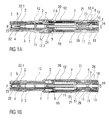
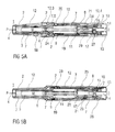
- FIGS 1 a and 1 b show two longitudinal sections of an auto-injector 1 in different section planes, the different section planes approximately 90° rotated to each other, wherein the auto-injector 1 is in an initial state prior to starting an injection.
- the auto-injector 1 comprises a chassis 2.
- the chassis 2 is generally considered as being fixed in position so motion of other components is described relative to the chassis 2.
- a syringe 3, e.g. a Hypak syringe, with a hollow injection needle 4 is arranged in a proximal part of the auto-injector 1.
- a protective needle sheath 5 is attached to the needle 4.
- the carrier 7 is a key element housing the syringe 3, the drive spring 8 and the plunger 9, which are the components required to eject the medicament M from the syringe 3. These components can therefore be referred to as a drive sub-assembly.
- the chassis 2 and the carrier 7 are arranged within a tubular case 12.
- a trigger button 13 is arranged at a distal end of the case 12.
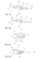
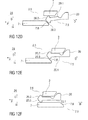
- a peg 14 protrudes from a distal end face of the trigger button 13 in the proximal direction P between two resilient arms 15 originating from the distal carrier end face 10 thus preventing them from flexing towards each other in an initial state A illustrated in figure 15A .
- FIG 15A only one of the resilient arms 15 is shown to illustrate the principle.
- the resilient arms 15 are caught in respective first recesses 16 in a distal plunger sleeve 17 attached distally to the thrust face 11 and arranged inside the drive spring 8.
- the engagement of the resilient arms 15 in the first recesses 16 prevents axial translation of the plunger 9 relative to the carrier 7.
- the resilient arms 15 are ramped in a manner to flex them inwards on relative motion between the plunger 9 and the carrier 7 under load of the drive spring 8, which is prevented by the peg 14 in the initial state A.
- a cap 22 is attached to the proximal end of the case 12 and the protective needle sheath 5 is still in place over the needle 4 and the needle hub.
- An inner sleeve 22.1 of the cap 22 is arranged inside the chassis 2 and over the protective needle sheath 5.
- a barb 23 is attached in the inner sleeve 22.1 . The barb 23 is engaged to the protective needle sheath 5 for joint axial translation.
- a sequence of operation of the auto-injector 1 is as follows:
- the user grabs the case 12 and places the chassis 2 protruding from the case 12 at the proximal end P against an injection site, e.g. a patient's skin.
- an injection site e.g. a patient's skin.
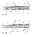
- the case 12 translates in the proximal direction P relative to the chassis 2 into an advanced position as illustrated in figures 3A and 3B .
- the second collar 21 is locked to the case 12 and is moved with the case 12 relative to the chassis 2 and relative to nearly all other components of the auto-injector 1 thus slightly compressing the control spring 19 against the first collar 20 which is prevented from moving in the proximal direction P by the chassis 2 due to a needle insertion control mechanism 24 being in a state A illustrated in detail in figure 12A .
- a resilient member in the shape of an arrowhead 20.1 is proximally arranged on the first collar 20. The first collar 20 with the arrowhead 20.1 is being forced in the proximal direction P under load of the compressed control spring 19.
- control spring 19 expands returning the auto-injector 1 to the initial condition after removal of the cap 22 as illustrated in figures 2A and 2B .
- the ramp on the first case detent 12.1 interacts with the outward first ramp 13.2 on the proximal beam 13.1 on the trigger button 13 deflecting the proximal beam 13.1 in the inward direction I thus engaging the inward second ramp 13.3 on the proximal beam 13.1 in a ramped carrier detent 7.4 arranged in the carrier 7.
- the case 12 is translated further in the proximal direction P it supports the proximal beam 13.1 outwardly thus locking the trigger button 13 to the carrier 7.
- the trigger button 13 now protrudes from the distal end D of the chassis 12 and is ready to be pressed.
- the user depresses the trigger button 13 in the proximal direction P.
- the carrier 7 As the trigger button 13 abuts against the carrier 7 the carrier 7 is pushing in the proximal direction P against the chassis 2, the carrier 7 and the chassis 2 interacting in the detent mechanism 18.
- the force exerted by the user pressing the trigger button 13 is resolved through the chassis 2 onto the injection site, not between the trigger button 13 and the case 12.
- the detent mechanism 18 provides a resistive force when the user pushes the trigger button 13. Once the user applies a force which exceeds a pre-determined value the detent mechanism 18 releases, initiating the injection cycle.
- the resilient beam 2.1 on the chassis 2 begins to bow under load from the rhomboid ramp member 7.1 on the carrier 7, storing elastic energy.
- the proximal fourth ramp 7.2 on the ramp member 7.1 friction between the contacting faces of the first beam head 2.2 and the proximal fourth ramp 7.2 prevents movement of the first beam head 2.2 in the outward direction O until the straightening force in the resiliently deformed beam 2.1 is sufficiently large to overcome it.
- the resilient beam 2.1 is deflected in the outward direction O moving out of the way of the carrier 7 thus allowing the carrier 7 to translate in the proximal direction P.
- the needle insertion control mechanism 24 is switched to a state B as illustrated in figure 12B .
- the carrier 7 has been translated in the proximal direction P in such a manner that the arrowhead 20.1 on the first collar 20 is no longer inwardly supported. This may be achieved by a second recess 7.5 in the carrier 7.
- the arrowhead 20.1 is now deflected in the inward direction I into the second recess 7.5 under load of the control spring 19 arriving at a state C as illustrated in figure 12C .
- the first collar 20 is now decoupled from the chassis 2.
- Figures 4A and 4B show the auto-injector 1 with the trigger button 13 depressed sufficiently for the control spring 19 to couple on to the carrier 7 and continue moving the carrier 7 forwards, but not yet abutting the case 12.
- the carrier 7 coupled to the first collar 20 is translated in the proximal direction P driven by the control spring 19.
- the syringe 3 and needle 4 are also translated resulting in the needle 4 protruding from the proximal end P and being inserted into the injection site.
- the trigger button 13 returns to its initial position relative to the case 12 and latches back to the case 12 from the carrier 7 as in state A in figure 16A .
- the carrier 7 translates further in the proximal direction P preventing inward deflection of the proximal beam 13.1 so the outward first ramp 13.2 cannot disengage from the first case detent 12.1.
- the plunger release mechanism 27 arrives in a state B shown in figure 15B with the resilient arms 15 no longer inwardly supported by the peg 14. Due to the ramped engagement of the resilient arms 15 in the first recess 16 they are deflected in the inward direction I under load of the drive spring 8 arriving in a state B illustrated in figure 15C . Hence, the plunger 9 is released from the carrier 7 and driven in the proximal direction P by the drive spring 8, ready to inject the medicament M.
- the force to pull the peg 14 out from between the resilient arms 15 is provided by the control spring 19 while the force required to deflect the resilient arms 15 out of engagement to the plunger 9 is provided by the drive spring 8.
- the arrowhead 20.1 travels proximally beyond the part of the chassis 2 shown in figures 12A to 12F next to an aperture 2.5 in the chassis 2.
- the arrowhead 20.1 will be kept from deflecting in the outward direction O by a first rib 12.3 on the case 12 (not illustrated in figures 12A to F , see figures 5A to 8A ) during about the second half of its motion for needle insertion.
- the needle 4 is now fully inserted into the injection site as illustrated in figures 6A and 6B .
- the time between the trigger button 13 pressed and the needle 4 being fully inserted is very short, however several mechanical operations take place in this time.
- the needle insertion depth is defined by the carrier 7 relative to the chassis 2 not relative to the case 12, so if the user flinches or fails to hold the auto-injector 1 hard against the skin, only the case 12 will move in the distal direction D while the injection depth remains constant.
- the noise component 28 comprises an elongate portion 28.1 arranged within the distal plunger sleeve 17 and a distal end plate 28.2 arranged between the carrier end face 10 and an end face of the trigger button 13.
- Two second resilient arms 30 originate from the distal carrier end face 10 and extend in the proximal direction P.
- a noise spring 29 is arranged to bias the noise component 28 in the distal direction D relative to the carrier 7 by proximally bearing against a rib on the second resilient arms 30 and distally against the noise component 28 (not illustrated).
- the noise component 28 is not illustrated in figures 16A , B and C for clarity since it does not affect the function of the button release mechanism 26.
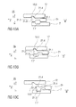
- a noise release mechanism 31 for releasing the noise component 28 is schematically illustrated in figures 14A, 14B and 14C .
- the noise release mechanism 31 comprises the second resilient arms 30.
- a ramped inward boss 30.1 is arranged on each second resilient arm 30 which is engaged to a respective outward eleventh ramp 28.3 on the elongate portion 28.1 of the noise component 28 in such a manner that the second resilient arm 30 is deflected in the outward direction O under load of the noise spring 29.
- the second resilient arms 30 are prevented from being outwardly deflected by outward support of the distal plunger sleeve 17 thus preventing translation of the noise component 28 relative to the carrier 7.
- the noise release mechanism 31 remains in state A until immediately prior to the end of injection with the stopper 6 having almost bottomed out in the syringe 3 as illustrated in figures 7A and 7B .
- the plunger 9 has been translated in the proximal direction P relative to the carrier 7 to such an extent that the second resilient arms 30 are no longer supported by the distal plunger sleeve 17.
- the noise release mechanism 31 has thus arrived in a state B illustrated in figure 14B .
- the second resilient arm 30 is outwardly deflected under load of the noise spring 29 thus disengaging the noise component 28 from the carrier 7 and allowing the noise component 28 to move in the distal direction D driven by the noise spring 29 in a state C illustrated in figure 14C .
- the noise component 28 is accelerated in the distal direction D and the distal end plate 28.2 impacts on the inside of the trigger button 13 producing audible and tactile feedback to the user that the injection is about finished.
- Figures 8A and 8B show the auto-injector 1 with the stopper 6 having entirely bottomed out in the syringe 3.
- FIGS. 12E and F The switching of the first collar 20 is illustrated in figures 12E and F .
- the case 12 has been allowed to move in the distal direction D under load of the control spring 19 during removal of the auto-injector 1 from the injection site.
- the first rib 12.3 (not illustrated, see figure 9A ) is removed from outwardly behind the arrowhead 20.1.
- the first collar 20 is still being pushed in the proximal direction P by the control spring 19.
- the syringe retraction control mechanism 25 switches from its state A (cf. figure 13A ) into a state B illustrated in figure 13B .
- the case 12 and the second collar 21 locked to the case 12 move together in the distal direction D while the carrier 7 is held in place by the detent mechanism 18 in its state C as described above (cf. figure 11C ). Due to this motion the inward boss 21.3 on the second beam head 21.2 of the proximal beam 21.1 on the second collar 21 no longer inwardly abuts the carrier 7.
- the detent mechanism 18 applies a small retarding force to the movement of the carrier 7 before the syringe retraction control mechanism 25 switches to state C as there is a small sliding force, applied by the second collar 21, pulling the carrier 7 in the distal direction D on translation of the case 12 in the distal direction D when the needle insertion control mechanism 24 has already been switched into state E. If the carrier 7 moves too far in the distal direction D before the second collar 21 switches, the case 12 runs out of travel before the inward boss 21.3 can deflect into the third recess 7.7 preventing retraction.
- the carrier 7 and hence the rhomboid ramp member 7.1 are translated in the distal direction D under load of the control spring 19.
- the distal fifth ramp 7.3 of the rhomboid ramp member 7.1 engages the proximal third ramp 2.3 on the first beam head 2.2 of the resilient beam 2.1 in a manner deflecting the resilient beam 2.1 in the inward direction I. This applies the small retarding force to the movement of the carrier 7 required for ensuring the switching of the second collar 21 to the carrier 7.
- the resilient beam 2.1 and the rhomboid ramp member 7.1 are offset sideways to allow the resilient beam 2.1 to pass without contacting the rhomboid ramp member 7.1 as soon as the first beam head 2.2 is entirely inwardly from the ramp member 7.1 in a state D illustrated in figure 11D .
- the control spring 19 is grounded at its proximal end in the case by the first collar 20 being abutted against the chassis 2.
- the distal end of the control spring 19 moves the second collar 21 in the distal direction D taking with it the carrier 7 and hence the syringe 3 with the needle 4 overcoming the detent mechanism 18 as illustrated in figure 11D .
- the needle 4 is retracted out of the skin by the auto-injector 1 as soon as the user allows the case 12 to translate sufficiently far as opposed to auto-injectors with needle shields which require the user to remove the auto-injector from the injection site thereby themselves pulling the needle out of the skin for allowing the needle shield to advance.
- the noise component 28 As the movement allowed of the noise component 28 is limited relative to the carrier 7 it is no longer in contact with the trigger button 13 which has moved in the distal direction D with the case 12 on removal from the injection site. When the retraction begins the noise spring 29 does not provide any retarding force. Once the noise component 28 hits the trigger button 13 again on retraction of the carrier 7 the noise spring 29 must be recompressed, reducing the force driving the final part of retraction. In order to ensure a reliable retraction despite this reducing force the control spring 19 must be appropriately dimensioned.
- the arrowhead 20.1 on the first collar 20 is inwardly supported by the carrier 7 in a state F illustrated in figure 12F and thus prevented from deflecting in the inward direction I.
- the outward sixth ramp 20.2 of the arrowhead 20.1 is engaged behind the first rib 12.3 on the case 12 preventing the case 12 from being pushed in the proximal direction P again.
- a clearance may be provided between the arrowhead 20.1 and the first rib 12.3 to allow for tolerances.
- the detent mechanism 18 returns to state A as in figure 11A locking the carrier 7 in position relative to the chassis 2 as it did initially, however it cannot be unlocked now as the case 12 cannot move relative to the chassis 2.
- a tab 20.4 on the first collar 20 is now visible through an indicator window 32 in the case 12 ⁇ indicating the auto-injector 1 has been used.
- Figure 17 is an isometric view of an alternative embodiment of the plunger release mechanism 27.
- the plunger release mechanism 27 prevents movement of the plunger 9 in the proximal direction P relative to the carrier 7 until the carrier 7 is moved in the proximal direction P for needle insertion.
- the alternative embodiment of figure 17 releases the plunger 9 by movement of the carrier 7 relative to the second collar 21.
- Figure 17 illustrates the plunger release mechanism 27 prior to plunger release.
- the second collar 21 is shown transparent to improve clarity.
- the plunger 9 is being pushed in the proximal direction P by the drive spring 8.
- the ramp member 9.1 on the collar 9 comes clear of the longitudinal rib 21.5 on the second collar 21 and can rotate past the proximal end of the longitudinal rib 21.5 due to its ramped engagement to the twelfth ramp 7.8 under load of the drive spring 8.
- the drive spring 8 advances the plunger 9 in the proximal direction P for injecting the medicament M.
- Figure 18 is a longitudinal section of an alternative embodiment of the button release mechanism 26.
- the button release mechanism 26 of figure 16 which gives the appearance of a revealing trigger button 13 on skin contact by switching the ground of the trigger button 13 between the carrier 7 and the case 12, the button release mechanism 26 of figure 18 starts with the trigger button 13 locked but protruding from the distal end of the case 12.
- the trigger button 13 has two proximal beams 13.1, each of them having a ramped outward boss 13.4.
- the ramped outward bosses 13.4 are engaged in respective fourth recesses 12.5 in the case 12.
- Disengaging the ramped outward bosses 13.4 from the fourth recesses 12.5 is prevented by the carrier 7 inwardly supporting the proximal beams 13.1 in a manner to keep the proximal beams 13.1 from deflecting inwardly.
- Inward protrusions 13.5 on the proximal beams 13.1 abut against a second rib 7.10 on the carrier 7 in a manner preventing the carrier 7 from moving further in the proximal direction P in the initial state.
- a first window 7.11 in the carrier 7 is moved behind the inward protrusion 13.5 so as to allow the proximal beams 13.1 to be inwardly deflected due to their ramped engagement in the fourth recesses 12.5 on depression of the trigger button 13.
- the proximal beams 13.1 are now outwardly supported by the case 12 and remain engaged to the carrier 7 even on retraction of the needle 4.
- the trigger button 13 does therefore not return to its initial position, indicating that the auto-injector 1 has been used.
- the button release mechanism 26 illustrated in figure 18 may preferably be combined with the plunger release mechanism 27 illustrated in figure 17 .
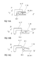
- Figures 19A and 19B show two longitudinal sections of an alternative embodiment of the detent mechanism 18.
- the detent mechanism 18 of figures 11A to 11D which may be referred to as a "race track" mechanism because of the first beam head 2.2 travelling around the rhomboid ramp member 7.1 has multiple functions which control the movement of the carrier 7 relative to the chassis 2.
- the alternative detent mechanism 18 of figures 19A and 19B uses three clips 7.12, 7.13, 2.6 to produce the same effect.
- the first clip 7.12 is arranged as an outwardly biased resilient beam on the carrier 7 extending from the carrier 7 in the proximal direction P.
- the first clip 7.12 is arranged to prevent the carrier 7 from being moved in the proximal direction P prior to the chassis 2 being depressed or rather the case 12 being translated on skin contact.
- the first clip 7.12 is composed of two sections side by side. A first section 7.14 prevents movement of the carrier 7 in the proximal direction P by abutting the chassis 2 in a recess.
- a second section 7.15 is arranged as an outwardly protruding clip head arranged to be ramped inwards by a ramp feature 12.6 on the chassis 12 for releasing the first clip 7.12 thereby unlocking the carrier 7 from the chassis 2 when the case 12 is being translated in the proximal direction P on skin contact.
- a longitudinal slot 2.7 in the chassis 2 is arranged for allowing the second section 7.15 to slide in the proximal direction P once the lock has been released.
- a slight friction force between the first clip 7.12 and the chassis 2 provides the retarding force required to ensure retraction.
- the second clip 7.13 is arranged as a resilient beam on the carrier 7 extending in the distal direction D having an outwardly protruding third beam head 7.16 with a proximal ramp.
- the third beam head 7.16 serves as a back stop against a third rib 2.9 on the chassis 2 for preventing the carrier 7 moving in the distal direction D from its initial position.
- the carrier 7 and chassis 2 are assembled with the second clip 7.13 in this position prior to inserting the syringe 3 into the carrier 7 which is facilitated by the proximal ramp on the third beam head 7.16.
- the syringe 3 locks the clip in place by preventing inward deflection thus creating a fixed stop.
- the third clip 2.6 is a resilient beam on the chassis 2 extending in the distal direction D.
- a ramped fourth beam head 2.8 on the third clip 2.6 is arranged to inwardly engage in a fifth recess 7.17 in the carrier 7.
- Figure 20 is a longitudinal section of a third embodiment of the detent mechanism 18 which is a variation on the embodiment of figures 19A and 19B .
- the detent function of the third clip 2.6 has been added into the first clip 7.12.
- the lock between the case 12 and the carrier 7 is released in the same way, but the detent is provided by deflecting the first clip 7.12 inwards a second level which is achieved by the chassis 2 not having a slot 2.7 for the second section 7.15.
- the second section 7.15 once ramped inwards by the ramp feature 12.6 on the case 12 has to be further ramped inwards inside the chassis 2 on axial load between the chassis 2 and the carrier 7, suddenly releasing their engagement.
- Figure 21 is a longitudinal section of an alternative embodiment of the noise release mechanism 31.
- the noise spring 29 acts between the carrier 7 and the noise component 28.
- the noise spring 29 acts between the case 12 and the noise component 28.
- the noise spring 29 is compressed as the noise component 28 moves with the carrier 7 relative to the case 12.
- the noise component 28 moves in the distal direction D and impacts the trigger button 13.
- the noise spring 29 is not being recompressed during needle retraction since it is grounded in the case 12 not in the carrier 7.
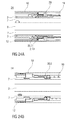
- Figures 22A and 22B show longitudinal sections of an alternative embodiment of the needle insertion control mechanism 24 which is also arranged to perform the detent function of the detent mechanism 18 on needle retraction and needle insertion.
- Figure 23 shows a corresponding isometric view.
- a fourth clip 20.5 on the first collar 20 is arranged as a resilient beam with a beam head having an inward proximal thirteenth ramp 20.6 for engaging a fourth rib 7.18 on the carrier 7 and outwardly supported by the case 12 so as to keep the first collar 20 engaged to the carrier 7 prior to use, during needle insertion and during injection.
- a sixth recess 12.7 in the case 12 is moved outwardly behind the fourth clip 20.5 allowing the fourth clip 20.5 to release when the carrier 7 is pulled in the distal direction D by the second collar 21. Since the fourth clip 20.5 has to be ramped outwards a small force is required to release the fourth clip 20.5, providing the retraction detent.
- a fifth clip 2.10 on the chassis 2 abuts a block 20.7 on the first collar 20 prior to use preventing the first collar 20 and hence the carrier 7 engaged to the first collar 20 from moving in the proximal direction P.
- the fifth clip 2.10 In order to release, the fifth clip 2.10 must be deflected outwards and over the block 20.7. Outward deflection of the fifth clip 2.10 is initially prevented by the case 12. Once the case 12 has moved on skin contact a second window 12.8 in the case 12 appears outwardly from the fifth clip 2.10 allowing outward deflection.
- the fifth clip 2.10 is then deflected by a fourteenth ramp 7.19 on the carrier 7 when the carrier 7 is pushed in the proximal direction P on button depression as the fourth clip 20.5 does allow translation of the carrier 7 in the proximal direction P relative to the first collar 20 but not the other way round.
- the detent for needle insertion is provided by having to deflect the fifth clip 2.10 when it is loaded by the control spring 19.
- Figures 24A and 24B show longitudinal sections of a third embodiment of the needle insertion control mechanism 24, also arranged to perform the functions of the detent mechanism 18.
- Figure 25 is an isometric view of the needle insertion control mechanism 24 of figure 24 .
- the embodiment is similar to that illustrated in figures 22A, 22B and 23 .
- the difference is that the fifth clip 2.10 is arranged on the first collar 20 and the block 20.7 is arranged on the chassis 2, i.e. their position has been switched, so there are two clips 2.10 and 20.5 on the first collar 20.
- the fourth clip 20.5 is identical to that in figure 22B . It keeps the first collar 20 connected to the carrier 7 until the needle retraction is triggered, ensuring full injection depth is reached and maintained until the retraction cycle is initiated by removing the auto-injector 1 from the skin.
- the fifth clip 2.10 provides the detent for needle insertion and releases the first collar 20 from the chassis 2, initiating needle insertion.
- the fifth clip 2.10 prevents the first collar 20 and hence the carrier 7 engaged to the first collar 20 from moving in the proximal direction P prior to use by abutting the block 20.7 on the chassis 2.
- the fifth clip 2.10 In order to release, the fifth clip 2.10 must be deflected outwards and over the block 20.7. Outward deflection of the fifth clip 2.10 is initially prevented by the case 12. Once the case 12 has moved on skin contact the second window 12.8 in the case 12 appears outwardly from the fifth clip 2.10 allowing outward deflection.
- the fifth clip 2.10 is then deflected by the fourteenth ramp 7.19 on the carrier 7 when the carrier 7 is pushed in the proximal direction P on button depression as the fourth clip 20.5 does allow translation of the carrier 7 in the proximal direction P relative to the first collar 20 but not the other way round.
- the detent for needle insertion is provided by having to deflect the fifth clip 2.10 when it is loaded by the control spring 19.
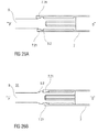
- Figures 26A and 26B show a longitudinal section of a third embodiment of the noise release mechanism 31.
- the plunger 9 comprises a proximally ramped rib 9.2 arranged to splay two seventh clips 7.21 on the carrier 7 immediately prior to the end of dose. When the proximally ramped rib 9.2 has travelled past the seventh clips 7.21 they snap back and impact the plunger 9 generating a sound.
- the tubular shape of the carrier 7 helps to transmit the sound.
- Figure 26A shows the noise release mechanism 31 before release.
- Figure 26B shows the noise release mechanism 31 after release.
- Proximal faces of the seventh clips 7.21 on the carrier 7 are axially offset to facilitate assembly by lifting the seventh clips 7.21 over the distal side of the proximally ramped rib 9.2 one by one.
- Figures 27A and 27B show longitudinal sections of another embodiment of the auto-injector 1 in different section planes, the different section planes approximately 90° rotated to each other, wherein the auto-injector 1 is in an initial state prior to starting an injection.
- the auto-injector 1 is essentially identical to the one described in figures 1 to 16 .
- the auto-injector 1 of this embodiment has a wrap-over sleeve trigger instead of a trigger button.
- the wrap-over sleeve trigger 12 is the same component as the case 12 which has a closed distal end face 12.10 other than the one in figures 1 to 16 .
- An internal trigger button 13 is arranged at the distal end inside the sleeve trigger 12. Other than in figures 1 to 16 the trigger button 13 is not visible nor does it protrude from the case 12 in any state. In the initial state a clearance 33 is provided between the distal end face 12.10 of the sleeve trigger 12 and the internal trigger button 13 allowing for some travel of the sleeve trigger 12 without interfering with the trigger button 13.
Landscapes
- Health & Medical Sciences (AREA)
- Engineering & Computer Science (AREA)
- Hematology (AREA)
- Anesthesiology (AREA)
- Biomedical Technology (AREA)
- Heart & Thoracic Surgery (AREA)
- Vascular Medicine (AREA)
- Life Sciences & Earth Sciences (AREA)
- Animal Behavior & Ethology (AREA)
- General Health & Medical Sciences (AREA)
- Public Health (AREA)
- Veterinary Medicine (AREA)
- Environmental & Geological Engineering (AREA)
- Infusion, Injection, And Reservoir Apparatuses (AREA)
- Pharmaceuticals Containing Other Organic And Inorganic Compounds (AREA)
Priority Applications (26)
| Application Number | Priority Date | Filing Date | Title |
|---|---|---|---|
| EP11155040A EP2489385A1 (en) | 2011-02-18 | 2011-02-18 | Auto-injector |
| MX2013009167A MX338740B (es) | 2011-02-18 | 2012-02-16 | Auto-inyector. |
| ARP120100525A AR085260A1 (es) | 2011-02-18 | 2012-02-16 | Auto-inyector |
| PL12704087T PL2675505T3 (pl) | 2011-02-18 | 2012-02-16 | Autostrzykawka |
| US13/983,809 US9925344B2 (en) | 2011-02-18 | 2012-02-16 | Auto-injector |
| NZ614211A NZ614211B2 (en) | 2011-02-18 | 2012-02-16 | Auto-injector |
| RU2013142356A RU2607926C2 (ru) | 2011-02-18 | 2012-02-16 | Автоматический инъектор |
| CN201280019049.0A CN103492002B (zh) | 2011-02-18 | 2012-02-16 | 自动注射装置 |
| HUE12704087A HUE024991T2 (en) | 2011-02-18 | 2012-02-16 | Automatic injector |
| BR112013020665A BR112013020665A2 (pt) | 2011-02-18 | 2012-02-16 | autoinjetor |
| CA2826331A CA2826331A1 (en) | 2011-02-18 | 2012-02-16 | Auto-injector |
| PCT/EP2012/052647 WO2012110578A1 (en) | 2011-02-18 | 2012-02-16 | Auto-injector |
| TW101105008A TWI597084B (zh) | 2011-02-18 | 2012-02-16 | 自動注射器(五) |
| AU2012217082A AU2012217082B2 (en) | 2011-02-18 | 2012-02-16 | Auto-injector |
| JP2013553932A JP6054312B2 (ja) | 2011-02-18 | 2012-02-16 | 自動注射器 |
| DK12704087.1T DK2675505T3 (en) | 2011-02-18 | 2012-02-16 | autoinjector |
| KR1020137024760A KR20140015382A (ko) | 2011-02-18 | 2012-02-16 | 자동 주사기 |
| SG2013059670A SG192636A1 (en) | 2011-02-18 | 2012-02-16 | Auto-injector |
| EP12704087.1A EP2675505B1 (en) | 2011-02-18 | 2012-02-16 | Auto-injector |
| ZA2013/05868A ZA201305868B (en) | 2011-02-18 | 2013-07-31 | Auto-injector |
| IL227759A IL227759A (en) | 2011-02-18 | 2013-08-01 | Self injector |
| HK14101344.5A HK1188162A1 (en) | 2011-02-18 | 2014-02-13 | Auto-injector |
| US15/897,872 US10894132B2 (en) | 2011-02-18 | 2018-02-15 | Auto-injector |
| US17/126,962 US11819670B2 (en) | 2011-02-18 | 2020-12-18 | Auto-injector |
| US18/487,215 US20240042137A1 (en) | 2011-02-18 | 2023-10-16 | Auto-Injector |
| US18/413,900 US12005240B2 (en) | 2011-02-18 | 2024-01-16 | Auto-injector |
Applications Claiming Priority (1)
| Application Number | Priority Date | Filing Date | Title |
|---|---|---|---|
| EP11155040A EP2489385A1 (en) | 2011-02-18 | 2011-02-18 | Auto-injector |
Publications (1)
| Publication Number | Publication Date |
|---|---|
| EP2489385A1 true EP2489385A1 (en) | 2012-08-22 |
Family
ID=44146348
Family Applications (2)
| Application Number | Title | Priority Date | Filing Date |
|---|---|---|---|
| EP11155040A Ceased EP2489385A1 (en) | 2011-02-18 | 2011-02-18 | Auto-injector |
| EP12704087.1A Active EP2675505B1 (en) | 2011-02-18 | 2012-02-16 | Auto-injector |
Family Applications After (1)
| Application Number | Title | Priority Date | Filing Date |
|---|---|---|---|
| EP12704087.1A Active EP2675505B1 (en) | 2011-02-18 | 2012-02-16 | Auto-injector |
Country Status (19)
| Country | Link |
|---|---|
| US (4) | US9925344B2 (ru) |
| EP (2) | EP2489385A1 (ru) |
| JP (1) | JP6054312B2 (ru) |
| KR (1) | KR20140015382A (ru) |
| CN (1) | CN103492002B (ru) |
| AR (1) | AR085260A1 (ru) |
| BR (1) | BR112013020665A2 (ru) |
| CA (1) | CA2826331A1 (ru) |
| DK (1) | DK2675505T3 (ru) |
| HK (1) | HK1188162A1 (ru) |
| HU (1) | HUE024991T2 (ru) |
| IL (1) | IL227759A (ru) |
| MX (1) | MX338740B (ru) |
| PL (1) | PL2675505T3 (ru) |
| RU (1) | RU2607926C2 (ru) |
| SG (1) | SG192636A1 (ru) |
| TW (1) | TWI597084B (ru) |
| WO (1) | WO2012110578A1 (ru) |
| ZA (1) | ZA201305868B (ru) |
Cited By (3)
| Publication number | Priority date | Publication date | Assignee | Title |
|---|---|---|---|---|
| WO2018037030A1 (en) * | 2016-08-26 | 2018-03-01 | Sanofi-Aventis Deutschland Gmbh | Audible indicator |
| WO2018037034A1 (en) * | 2016-08-26 | 2018-03-01 | Sanofi-Aventis Deutschland Gmbh | Audible indicator |
| FR3103708A1 (fr) * | 2019-12-02 | 2021-06-04 | Aptar France Sas | Dispositif d'injection de produit fluide |
Families Citing this family (30)
| Publication number | Priority date | Publication date | Assignee | Title |
|---|---|---|---|---|
| US9974904B2 (en) | 2008-05-20 | 2018-05-22 | Avant Medical Corp. | Autoinjector system |
| US8177749B2 (en) | 2008-05-20 | 2012-05-15 | Avant Medical Corp. | Cassette for a hidden injection needle |
| US8052645B2 (en) | 2008-07-23 | 2011-11-08 | Avant Medical Corp. | System and method for an injection using a syringe needle |
| EP2489386A1 (en) | 2011-02-18 | 2012-08-22 | Sanofi-Aventis Deutschland GmbH | Auto-injector |
| EP2489387A1 (en) | 2011-02-18 | 2012-08-22 | Sanofi-Aventis Deutschland GmbH | Auto-injector |
| EP2489384A1 (en) * | 2011-02-18 | 2012-08-22 | Sanofi-Aventis Deutschland GmbH | Auto-injector |
| EP2489385A1 (en) | 2011-02-18 | 2012-08-22 | Sanofi-Aventis Deutschland GmbH | Auto-injector |
| EP2489380A1 (en) | 2011-02-18 | 2012-08-22 | Sanofi-Aventis Deutschland GmbH | Injection device |
| EP2489382A1 (en) | 2011-02-18 | 2012-08-22 | Sanofi-Aventis Deutschland GmbH | Auto-injector |
| EP2489381A1 (en) | 2011-02-18 | 2012-08-22 | Sanofi-Aventis Deutschland GmbH | Auto-injector |
| EP2489389A1 (en) | 2011-02-18 | 2012-08-22 | Sanofi-Aventis Deutschland GmbH | Detent mechanism |
| EP2489388A1 (en) | 2011-02-18 | 2012-08-22 | Sanofi-Aventis Deutschland GmbH | Auto-injector |
| PT2699293T (pt) | 2011-04-20 | 2019-05-21 | Amgen Inc | Aparelho de autoinjeção |
| USD898908S1 (en) | 2012-04-20 | 2020-10-13 | Amgen Inc. | Pharmaceutical product cassette for an injection device |
| EP2662104A1 (en) * | 2012-05-07 | 2013-11-13 | Sanofi-Aventis Deutschland GmbH | Detent mechanism for a medicament delivery device |
| EP2968760B1 (en) | 2013-03-15 | 2024-01-03 | Amgen Inc. | Drug cassette, autoinjector, and autoinjector system |
| TWI639449B (zh) | 2013-03-15 | 2018-11-01 | 美商安美基公司 | 用於注射器之匣盒 |
| EP3590568A1 (de) | 2013-03-22 | 2020-01-08 | TecPharma Licensing AG | Substanzabgabevorrichtung mit signalvorrichtung |
| EP2823841A1 (en) | 2013-07-09 | 2015-01-14 | Sanofi-Aventis Deutschland GmbH | Autoinjector |
| EP2923714A1 (en) | 2014-03-28 | 2015-09-30 | Sanofi-Aventis Deutschland GmbH | Autoinjector triggered by skin contact |
| CN112545886A (zh) | 2015-03-10 | 2021-03-26 | 里珍纳龙药品有限公司 | 无菌刺穿系统和方法 |
| JP6716542B2 (ja) * | 2015-03-27 | 2020-07-01 | テルモ株式会社 | 注射針組立体および薬剤注射装置 |
| FR3041262B1 (fr) * | 2015-09-22 | 2020-11-20 | Aptar France Sas | Autoinjecteur |
| CN108883233B (zh) * | 2016-04-15 | 2021-10-01 | 泰尔茂株式会社 | 注射器用筒体及其制造方法以及预灌封注射器 |
| EP3311863A1 (en) | 2016-10-24 | 2018-04-25 | Carebay Europe Ltd. | Medicament delivery device having a cap assembly |
| AU2018260992B9 (en) | 2017-05-05 | 2024-02-15 | Regeneron Pharmaceuticals, Inc. | Auto-injector |
| CA3093055A1 (en) | 2018-03-13 | 2019-09-19 | Mylan Uk Healthcare Ltd. | Devices for injecting medicaments and methods of use |
| CN113368344B (zh) * | 2021-05-26 | 2022-07-15 | 宁波易舒医疗科技有限公司 | 一种轴向驱动机构、自动注射装置及其使用方法 |
| CN113368343B (zh) * | 2021-05-26 | 2022-06-10 | 宁波易舒医疗科技有限公司 | 一种推力机构、应用该机构的自动注射装置及其使用方法 |
| USD1007676S1 (en) | 2021-11-16 | 2023-12-12 | Regeneron Pharmaceuticals, Inc. | Wearable autoinjector |
Citations (4)
| Publication number | Priority date | Publication date | Assignee | Title |
|---|---|---|---|---|
| US20020095120A1 (en) | 2000-08-29 | 2002-07-18 | Andre Larsen | Automatic injection device |
| WO2010035060A1 (en) * | 2008-09-29 | 2010-04-01 | Becton Dickinson France | Automatic injection device |
| US7749195B2 (en) * | 2003-09-11 | 2010-07-06 | Tecpharma Licensing Ag | Administration device with an insertion mechanism and a delivery mechanism |
| US20100292653A1 (en) * | 2007-09-25 | 2010-11-18 | Becton Dickinson France S.A.S. | Autoinjector with trigger positionable in active position by movement of a safety shield and indication of the active position |
Family Cites Families (101)
| Publication number | Priority date | Publication date | Assignee | Title |
|---|---|---|---|---|
| JPH0826221B2 (ja) | 1987-09-14 | 1996-03-13 | 呉羽化学工業株式会社 | ポリアリーレンチオエーテル組成物及びその成形物 |
| JPH02202549A (ja) | 1989-01-30 | 1990-08-10 | Mitsubishi Rayon Co Ltd | ポリアリーレンサルファイド樹脂組成物 |
| GB8926825D0 (en) | 1989-11-28 | 1990-01-17 | Glaxo Group Ltd | Device |
| US6287610B1 (en) | 1991-11-20 | 2001-09-11 | Monfort, Inc. | Method for increasing the tenderness of a meat product |
| DE69319753T2 (de) | 1992-11-19 | 1999-04-15 | Galli Rosaria & C | Automatische injektionsvorrichtung für vorgefüllte spritzen |
| US5320609A (en) | 1992-12-07 | 1994-06-14 | Habley Medical Technology Corporation | Automatic pharmaceutical dispensing syringe |
| US5599309A (en) | 1993-03-24 | 1997-02-04 | Owen Mumford Limited | Injection devices |
| FR2715071B1 (fr) | 1994-01-17 | 1996-03-01 | Aguettant Lab | Injecteur automatique de médicament. |
| US5478316A (en) | 1994-02-02 | 1995-12-26 | Becton, Dickinson And Company | Automatic self-injection device |
| NZ302558A (en) | 1995-03-07 | 1999-11-29 | Lilly Co Eli | Dispensing apparatus with a medication cartridge with a manually adjustable metering mechanism |
| FR2733155B1 (fr) | 1995-04-18 | 1997-09-19 | Tebro | Auto-injecteur rechargeable |
| US5746215A (en) | 1996-11-01 | 1998-05-05 | U.S. Medical Instruments, Inc. | IV infusion or collection device with extendable and retractable needle |
| US6096010A (en) * | 1998-02-20 | 2000-08-01 | Becton, Dickinson And Company | Repeat-dose medication delivery pen |
| DE19822031C2 (de) | 1998-05-15 | 2000-03-23 | Disetronic Licensing Ag | Autoinjektionsgerät |
| SE9803662D0 (sv) | 1998-10-26 | 1998-10-26 | Pharmacia & Upjohn Ab | Autoinjector |
| FR2787246B1 (fr) | 1998-12-09 | 2001-02-23 | Alpes Lasers | Laser de type semi-conducteur |
| EP1313520B1 (en) | 2000-08-02 | 2016-08-31 | Becton Dickinson and Company | Pen needle and safety shield system |
| RU2203688C2 (ru) * | 2000-08-30 | 2003-05-10 | Конструкторское бюро "Полет" ГУДП ГП "Производственное объединение "Полет" | Шприц |
| AU2001292581B2 (en) | 2000-10-09 | 2006-05-18 | Eli Lilly And Company | Pen device for administration of parathyroid hormone |
| EP1341453B1 (en) | 2000-10-13 | 2009-04-15 | Alza Corporation | Apparatus and method for piercing skin with microprotrusions |
| SE518981C2 (sv) | 2000-12-14 | 2002-12-17 | Shl Medical Ab | Autoinjektor |
| US6461362B1 (en) | 2001-04-30 | 2002-10-08 | Mdc Investment Holdings, Inc. | Catheter insertion device with retractable needle |
| JP4633094B2 (ja) | 2001-12-13 | 2011-02-16 | パナソニック株式会社 | 医療用投与器具 |
| US6808507B2 (en) * | 2002-05-10 | 2004-10-26 | Cambridge Biostability Ltd. | Safety injectors |
| AU2003280270B2 (en) | 2002-11-25 | 2008-01-24 | Tecpharma Licensing Ag | Injection apparatus comprising a needle-protecting device |
| EP1572271A1 (de) | 2002-11-25 | 2005-09-14 | Tecpharma Licensing AG | Autoinjektor mit rückstellbarer auslösesicherung |
| GB0312852D0 (en) | 2003-06-05 | 2003-07-09 | Owen Mumford Ltd | Improvements relating to syringe firing mechanisms |
| US20050027255A1 (en) * | 2003-07-31 | 2005-02-03 | Sid Technologies, Llc | Automatic injector |
| DE10351598A1 (de) | 2003-11-05 | 2005-06-16 | Tecpharma Licensing Ag | Autoinjektionsvorrichtung |
| DE10351599A1 (de) | 2003-11-05 | 2005-06-16 | Tecpharma Licensing Ag | Autoinjektionsvorrichtung |
| US20050101919A1 (en) * | 2003-11-07 | 2005-05-12 | Lennart Brunnberg | Device for an injector |
| JP2007514487A (ja) * | 2003-12-18 | 2007-06-07 | テクファーマ・ライセンシング・アクチェンゲゼルシャフト | トリガー作動可能な注射装置 |
| CH696421A5 (de) | 2003-12-18 | 2007-06-15 | Tecpharma Licensing Ag | Autoinjektor mit Arretierung des Wirkstoffbehälters. |
| GB2410188B (en) | 2004-01-23 | 2006-01-25 | Medical House Plc | Injection device |
| PL1715903T3 (pl) | 2004-01-23 | 2008-03-31 | The Medical House Plc | Urządzenie wstrzykujące |
| US20050222539A1 (en) | 2004-03-30 | 2005-10-06 | Pediamed Pharmaceuticals, Inc. | Automatic injection device |
| GB2414400B (en) | 2004-05-28 | 2009-01-14 | Cilag Ag Int | Injection device |
| GB2414404B (en) | 2004-05-28 | 2009-06-03 | Cilag Ag Int | Injection device |
| US7160219B2 (en) | 2004-06-03 | 2007-01-09 | Arvinmeritor Technology Llc. | Method and apparatus for lubricating a differential gear assembly |
| US9220595B2 (en) | 2004-06-23 | 2015-12-29 | Orthovita, Inc. | Shapeable bone graft substitute and instruments for delivery thereof |
| US8048035B2 (en) | 2004-08-06 | 2011-11-01 | Meridian Medical Technologies, Inc. | Automatic injector with needle cover |
| DE102004041151A1 (de) | 2004-08-25 | 2006-03-02 | Tecpharma Licensing Ag | Dosiervorrichtung mit Ablaufsteuerung |
| WO2006052737A1 (en) | 2004-11-04 | 2006-05-18 | Sid Technologies, Llc | Automatic injector |
| DE102004063648A1 (de) | 2004-12-31 | 2006-07-20 | Tecpharma Licensing Ag | Injektions- oder Infusionsgerät mit Lebensdauer-Ermittlungseinrichtung |
| ES2689536T3 (es) | 2005-01-25 | 2018-11-14 | Novo Nordisk A/S | Dispositivo de inyección con un mecanismo de realimentación al final de la dosis |
| US7407494B2 (en) | 2005-01-31 | 2008-08-05 | Bostroem Anders | Device for delivering medicament |
| JP5222722B2 (ja) | 2005-04-20 | 2013-06-26 | ベクトン・ディキンソン・フランス・エス.エー.エス. | 注入セットおよび注入補助装置 |
| WO2006124891A2 (en) | 2005-05-16 | 2006-11-23 | Mallinckrodt Inc. | Radiopharmaceutical container having syringe capper |
| EP1893256B1 (en) | 2005-06-16 | 2012-09-26 | Novo Nordisk A/S | Method and apparatus for assisting patients in self administration of medication |
| EP1904131A2 (en) | 2005-06-21 | 2008-04-02 | Eli Lilly And Company | Apparatus and method for injecting a pharmaceutical |
| DE202005010389U1 (de) | 2005-07-01 | 2005-09-08 | Tecpharma Licensing Ag | Magnetische Kolbenstangenrückführung und Kolbenstangenfixierung |
| DE102005052460A1 (de) | 2005-11-03 | 2007-05-16 | Tecpharma Licensing Ag | Autoinjektor - Ablaufsteuerung für Behältniswechsel |
| WO2007108384A1 (ja) | 2006-03-16 | 2007-09-27 | Toray Industries, Inc. | ポリフェニレンスルフィド樹脂組成物、その製造方法および成形品 |
| FR2899482A1 (fr) | 2006-04-11 | 2007-10-12 | Becton Dickinson France Soc Pa | Dispositif d'injection automatique |
| GB2465919B (en) | 2006-05-10 | 2010-12-08 | Owen Mumford Ltd | Injection device with cap that can be re-fitted post injection |
| DE102006041128A1 (de) | 2006-09-01 | 2008-03-20 | Tecpharma Licensing Ag | Sicherheitsnadelmodul mit einem Rastmechanismus und einer Verwendungskennzeichnung |
| FR2905273B1 (fr) | 2006-09-06 | 2009-04-03 | Becton Dickinson France Soc Pa | Dispositif d'injection automatique avec moyen de temporisation. |
| GB2443606B (en) | 2006-11-13 | 2011-07-20 | Cilag Gmbh Int | Injection device |
| DK1932558T3 (da) | 2006-12-13 | 2011-09-05 | Shl Group Ab | Autoinjektor |
| US20080228147A1 (en) | 2007-03-15 | 2008-09-18 | Bristol-Myers Squibb Company | Injector for use with pre-filled syringes and method of assembly |
| DE102007013836A1 (de) | 2007-03-22 | 2008-09-25 | Tecpharma Licensing Ag | Injektionsvorrichtung mit gesteuertem Nadelrückzug |
| CN101678168B (zh) | 2007-03-22 | 2013-03-06 | 特克法马许可公司 | 具有受控制的注射针拉回功能的注射装置 |
| CN101678167B (zh) | 2007-03-22 | 2013-09-18 | 特克法马许可公司 | 注射装置中的弹簧机构 |
| DE102007013838A1 (de) * | 2007-03-22 | 2008-09-25 | Tecpharma Licensing Ag | Injektionsvorrichtung mit zeitkonstantem Ausschüttsignal |
| DE102007016811A1 (de) * | 2007-04-05 | 2008-10-09 | Tecpharma Licensing Ag | Vorrichtung zur Verabreichung eines fluiden Wirkstoffes aus einer Mehrkammerampulle |
| US8057427B2 (en) | 2007-05-09 | 2011-11-15 | Meridian Medical Technologies, Inc. | Drug delivery system with a small amount of a therapeutic agent |
| DE102007030327A1 (de) | 2007-06-29 | 2009-01-02 | Tecpharma Licensing Ag | Injektionsvorrichtung mit einer Feder für eine Nadelschutzhülse |
| CN101687079B (zh) | 2007-07-06 | 2013-01-02 | 诺沃-诺迪斯克有限公司 | 自动注射装置 |
| GB2451663B (en) | 2007-08-08 | 2012-09-26 | Cilag Gmbh Int | Injection device |
| GB2452030A (en) | 2007-08-10 | 2009-02-25 | Owen Mumford Ltd | Injection devices |
| WO2009040602A1 (en) | 2007-09-25 | 2009-04-02 | Becton Dickinson France | Autoinject0r with deactivating means moveable by a safety shield |
| US8409141B2 (en) | 2007-11-12 | 2013-04-02 | Bang & Olufsen Medicom A/S | Auto injector with automatic needle retraction |
| EP2237817B1 (en) | 2007-11-14 | 2019-02-13 | SHL Group AB | Automatic injection device with actively triggered syringe withdrawal |
| PL2234661T3 (pl) | 2007-12-20 | 2013-09-30 | Novo Nordisk As | Przyrząd do wstrzykiwania do dostarczania ustalonej dawki płynnego leku |
| GB0801874D0 (en) | 2008-02-01 | 2008-03-12 | Liversidge Barry P | Injection device |
| GB2460398A (en) | 2008-05-20 | 2009-12-02 | Owen Mumford Ltd | Auto-injector having a magnetic injection indicator and a needle sheath retainer |
| EP3581223A3 (en) | 2008-07-18 | 2020-03-18 | UCB Biopharma SRL | Systems for automatically administering medication |
| EP3508237A1 (en) | 2008-09-29 | 2019-07-10 | Becton Dickinson France | Autoinjector with audible indication of completed delivery |
| WO2010035056A1 (en) | 2008-09-29 | 2010-04-01 | Becton Dickinson France | Automatic injection device with sensitive indicator of completed injection |
| ES2728804T3 (es) | 2008-09-29 | 2019-10-28 | Becton Dickinson France | Dispositivo de inyección automática con indicador audible de inyección completa |
| GB0901801D0 (en) | 2009-02-05 | 2009-03-11 | Medical House Plc The | Improved autoinjector |
| GB2469672B (en) | 2009-04-23 | 2013-09-25 | Medical House Ltd | Improved autoinjector |
| US20100286612A1 (en) | 2009-05-06 | 2010-11-11 | William Cirillo | Medication injection supervisor device |
| GB0913385D0 (en) | 2009-07-31 | 2009-09-16 | Medical House The Plc | Improved autoinjector |
| JP5701889B2 (ja) | 2009-10-08 | 2015-04-15 | エス・ホー・エル・グループ・アクチボラゲットShl Group Ab | 薬物供給装置 |
| DK2533834T3 (en) | 2010-02-09 | 2018-01-15 | Shl Group Ab | DRUG DELIVERY DEVICES |
| DK2552517T3 (en) | 2010-03-31 | 2017-04-03 | Shl Group Ab | PHARMACEUTICAL DELIVERY DEVICE INCLUDING FEEDBACK SIGNALS |
| EP2399635A1 (en) | 2010-06-28 | 2011-12-28 | Sanofi-Aventis Deutschland GmbH | Auto-injector |
| RU2585693C2 (ru) | 2010-10-08 | 2016-06-10 | Санофи-Авентис Дойчланд Гмбх | Автоинъектор |
| GB201021767D0 (en) | 2010-12-22 | 2011-02-02 | Owen Mumford Ltd | Autoinjectors |
| EP2489380A1 (en) | 2011-02-18 | 2012-08-22 | Sanofi-Aventis Deutschland GmbH | Injection device |
| EP2489389A1 (en) | 2011-02-18 | 2012-08-22 | Sanofi-Aventis Deutschland GmbH | Detent mechanism |
| EP2489390A1 (en) | 2011-02-18 | 2012-08-22 | Sanofi-Aventis Deutschland GmbH | Detent mechanism |
| EP2489383A1 (en) | 2011-02-18 | 2012-08-22 | Sanofi-Aventis Deutschland GmbH | Auto-injector |
| EP2489388A1 (en) | 2011-02-18 | 2012-08-22 | Sanofi-Aventis Deutschland GmbH | Auto-injector |
| EP2489382A1 (en) | 2011-02-18 | 2012-08-22 | Sanofi-Aventis Deutschland GmbH | Auto-injector |
| EP2489387A1 (en) | 2011-02-18 | 2012-08-22 | Sanofi-Aventis Deutschland GmbH | Auto-injector |
| EP2489385A1 (en) | 2011-02-18 | 2012-08-22 | Sanofi-Aventis Deutschland GmbH | Auto-injector |
| EP2489381A1 (en) | 2011-02-18 | 2012-08-22 | Sanofi-Aventis Deutschland GmbH | Auto-injector |
| EP2489386A1 (en) | 2011-02-18 | 2012-08-22 | Sanofi-Aventis Deutschland GmbH | Auto-injector |
| EP2489384A1 (en) | 2011-02-18 | 2012-08-22 | Sanofi-Aventis Deutschland GmbH | Auto-injector |
-
2011
- 2011-02-18 EP EP11155040A patent/EP2489385A1/en not_active Ceased
-
2012
- 2012-02-16 MX MX2013009167A patent/MX338740B/es active IP Right Grant
- 2012-02-16 CA CA2826331A patent/CA2826331A1/en not_active Abandoned
- 2012-02-16 US US13/983,809 patent/US9925344B2/en active Active
- 2012-02-16 WO PCT/EP2012/052647 patent/WO2012110578A1/en active Application Filing
- 2012-02-16 EP EP12704087.1A patent/EP2675505B1/en active Active
- 2012-02-16 AR ARP120100525A patent/AR085260A1/es not_active Application Discontinuation
- 2012-02-16 DK DK12704087.1T patent/DK2675505T3/en active
- 2012-02-16 JP JP2013553932A patent/JP6054312B2/ja active Active
- 2012-02-16 SG SG2013059670A patent/SG192636A1/en unknown
- 2012-02-16 RU RU2013142356A patent/RU2607926C2/ru not_active IP Right Cessation
- 2012-02-16 TW TW101105008A patent/TWI597084B/zh not_active IP Right Cessation
- 2012-02-16 KR KR1020137024760A patent/KR20140015382A/ko unknown
- 2012-02-16 PL PL12704087T patent/PL2675505T3/pl unknown
- 2012-02-16 BR BR112013020665A patent/BR112013020665A2/pt not_active IP Right Cessation
- 2012-02-16 CN CN201280019049.0A patent/CN103492002B/zh active Active
- 2012-02-16 HU HUE12704087A patent/HUE024991T2/en unknown
-
2013
- 2013-07-31 ZA ZA2013/05868A patent/ZA201305868B/en unknown
- 2013-08-01 IL IL227759A patent/IL227759A/en active IP Right Grant
-
2014
- 2014-02-13 HK HK14101344.5A patent/HK1188162A1/xx unknown
-
2018
- 2018-02-15 US US15/897,872 patent/US10894132B2/en active Active
-
2020
- 2020-12-18 US US17/126,962 patent/US11819670B2/en active Active
-
2023
- 2023-10-16 US US18/487,215 patent/US20240042137A1/en active Pending
Patent Citations (4)
| Publication number | Priority date | Publication date | Assignee | Title |
|---|---|---|---|---|
| US20020095120A1 (en) | 2000-08-29 | 2002-07-18 | Andre Larsen | Automatic injection device |
| US7749195B2 (en) * | 2003-09-11 | 2010-07-06 | Tecpharma Licensing Ag | Administration device with an insertion mechanism and a delivery mechanism |
| US20100292653A1 (en) * | 2007-09-25 | 2010-11-18 | Becton Dickinson France S.A.S. | Autoinjector with trigger positionable in active position by movement of a safety shield and indication of the active position |
| WO2010035060A1 (en) * | 2008-09-29 | 2010-04-01 | Becton Dickinson France | Automatic injection device |
Non-Patent Citations (1)
| Title |
|---|
| "Remington's Pharmaceutical Sciences", 1985, MARK PUBLISHING COMPANY |
Cited By (7)
| Publication number | Priority date | Publication date | Assignee | Title |
|---|---|---|---|---|
| WO2018037030A1 (en) * | 2016-08-26 | 2018-03-01 | Sanofi-Aventis Deutschland Gmbh | Audible indicator |
| WO2018037034A1 (en) * | 2016-08-26 | 2018-03-01 | Sanofi-Aventis Deutschland Gmbh | Audible indicator |
| US11369744B2 (en) | 2016-08-26 | 2022-06-28 | Sanofi-Aventis Deutschland Gmbh | Audible indicator |
| CN115501428A (zh) * | 2016-08-26 | 2022-12-23 | 赛诺菲-安万特德国有限公司 | 听觉指示器 |
| US11771838B2 (en) | 2016-08-26 | 2023-10-03 | Sanofi-Aventis Deutschland Gmbh | Audible indicator |
| FR3103708A1 (fr) * | 2019-12-02 | 2021-06-04 | Aptar France Sas | Dispositif d'injection de produit fluide |
| EP3831431A1 (fr) * | 2019-12-02 | 2021-06-09 | APTAR France SAS | Dispositif d'injection de produit fluide |
Also Published As
Similar Documents
| Publication | Publication Date | Title |
|---|---|---|
| US11819670B2 (en) | Auto-injector | |
| EP2675506B1 (en) | Auto-injector | |
| EP2675507B1 (en) | Auto-injector | |
| EP2675503B1 (en) | Auto-injector | |
| EP2675508B1 (en) | Auto-injector | |
| US9604003B2 (en) | Auto-injector | |
| EP2675501B1 (en) | Auto-injector | |
| EP2675504B1 (en) | Auto-injector | |
| AU2012217082B2 (en) | Auto-injector |
Legal Events
| Date | Code | Title | Description |
|---|---|---|---|
| PUAI | Public reference made under article 153(3) epc to a published international application that has entered the european phase |
Free format text: ORIGINAL CODE: 0009012 |
|
| AK | Designated contracting states |
Kind code of ref document: A1 Designated state(s): AL AT BE BG CH CY CZ DE DK EE ES FI FR GB GR HR HU IE IS IT LI LT LU LV MC MK MT NL NO PL PT RO RS SE SI SK SM TR |
|
| AX | Request for extension of the european patent |
Extension state: BA ME |
|
| STAA | Information on the status of an ep patent application or granted ep patent |
Free format text: STATUS: THE APPLICATION HAS BEEN REFUSED |
|
| 18R | Application refused |
Effective date: 20120927 |