EP2489381A1 - Auto-injector - Google Patents
Auto-injector Download PDFInfo
- Publication number
- EP2489381A1 EP2489381A1 EP11155032A EP11155032A EP2489381A1 EP 2489381 A1 EP2489381 A1 EP 2489381A1 EP 11155032 A EP11155032 A EP 11155032A EP 11155032 A EP11155032 A EP 11155032A EP 2489381 A1 EP2489381 A1 EP 2489381A1
- Authority
- EP
- European Patent Office
- Prior art keywords
- carrier
- chassis
- case
- needle
- auto
- Prior art date
- Legal status (The legal status is an assumption and is not a legal conclusion. Google has not performed a legal analysis and makes no representation as to the accuracy of the status listed.)
- Ceased
Links
Images


Classifications
-
- A—HUMAN NECESSITIES
- A61—MEDICAL OR VETERINARY SCIENCE; HYGIENE
- A61M—DEVICES FOR INTRODUCING MEDIA INTO, OR ONTO, THE BODY; DEVICES FOR TRANSDUCING BODY MEDIA OR FOR TAKING MEDIA FROM THE BODY; DEVICES FOR PRODUCING OR ENDING SLEEP OR STUPOR
- A61M5/00—Devices for bringing media into the body in a subcutaneous, intra-vascular or intramuscular way; Accessories therefor, e.g. filling or cleaning devices, arm-rests
- A61M5/178—Syringes
- A61M5/31—Details
- A61M5/315—Pistons; Piston-rods; Guiding, blocking or restricting the movement of the rod or piston; Appliances on the rod for facilitating dosing ; Dosing mechanisms
- A61M5/31501—Means for blocking or restricting the movement of the rod or piston
-
- A—HUMAN NECESSITIES
- A61—MEDICAL OR VETERINARY SCIENCE; HYGIENE
- A61M—DEVICES FOR INTRODUCING MEDIA INTO, OR ONTO, THE BODY; DEVICES FOR TRANSDUCING BODY MEDIA OR FOR TAKING MEDIA FROM THE BODY; DEVICES FOR PRODUCING OR ENDING SLEEP OR STUPOR
- A61M5/00—Devices for bringing media into the body in a subcutaneous, intra-vascular or intramuscular way; Accessories therefor, e.g. filling or cleaning devices, arm-rests
- A61M5/178—Syringes
- A61M5/31—Details
- A61M5/32—Needles; Details of needles pertaining to their connection with syringe or hub; Accessories for bringing the needle into, or holding the needle on, the body; Devices for protection of needles
-
- A—HUMAN NECESSITIES
- A61—MEDICAL OR VETERINARY SCIENCE; HYGIENE
- A61M—DEVICES FOR INTRODUCING MEDIA INTO, OR ONTO, THE BODY; DEVICES FOR TRANSDUCING BODY MEDIA OR FOR TAKING MEDIA FROM THE BODY; DEVICES FOR PRODUCING OR ENDING SLEEP OR STUPOR
- A61M5/00—Devices for bringing media into the body in a subcutaneous, intra-vascular or intramuscular way; Accessories therefor, e.g. filling or cleaning devices, arm-rests
- A61M5/178—Syringes
- A61M5/20—Automatic syringes, e.g. with automatically actuated piston rod, with automatic needle injection, filling automatically
- A61M5/2033—Spring-loaded one-shot injectors with or without automatic needle insertion
-
- A—HUMAN NECESSITIES
- A61—MEDICAL OR VETERINARY SCIENCE; HYGIENE
- A61M—DEVICES FOR INTRODUCING MEDIA INTO, OR ONTO, THE BODY; DEVICES FOR TRANSDUCING BODY MEDIA OR FOR TAKING MEDIA FROM THE BODY; DEVICES FOR PRODUCING OR ENDING SLEEP OR STUPOR
- A61M5/00—Devices for bringing media into the body in a subcutaneous, intra-vascular or intramuscular way; Accessories therefor, e.g. filling or cleaning devices, arm-rests
- A61M5/178—Syringes
- A61M5/31—Details
- A61M5/315—Pistons; Piston-rods; Guiding, blocking or restricting the movement of the rod or piston; Appliances on the rod for facilitating dosing ; Dosing mechanisms
- A61M5/31511—Piston or piston-rod constructions, e.g. connection of piston with piston-rod
-
- A—HUMAN NECESSITIES
- A61—MEDICAL OR VETERINARY SCIENCE; HYGIENE
- A61M—DEVICES FOR INTRODUCING MEDIA INTO, OR ONTO, THE BODY; DEVICES FOR TRANSDUCING BODY MEDIA OR FOR TAKING MEDIA FROM THE BODY; DEVICES FOR PRODUCING OR ENDING SLEEP OR STUPOR
- A61M5/00—Devices for bringing media into the body in a subcutaneous, intra-vascular or intramuscular way; Accessories therefor, e.g. filling or cleaning devices, arm-rests
- A61M5/178—Syringes
- A61M5/31—Details
- A61M5/315—Pistons; Piston-rods; Guiding, blocking or restricting the movement of the rod or piston; Appliances on the rod for facilitating dosing ; Dosing mechanisms
- A61M5/31565—Administration mechanisms, i.e. constructional features, modes of administering a dose
- A61M5/31566—Means improving security or handling thereof
- A61M5/3157—Means providing feedback signals when administration is completed
-
- A—HUMAN NECESSITIES
- A61—MEDICAL OR VETERINARY SCIENCE; HYGIENE
- A61M—DEVICES FOR INTRODUCING MEDIA INTO, OR ONTO, THE BODY; DEVICES FOR TRANSDUCING BODY MEDIA OR FOR TAKING MEDIA FROM THE BODY; DEVICES FOR PRODUCING OR ENDING SLEEP OR STUPOR
- A61M5/00—Devices for bringing media into the body in a subcutaneous, intra-vascular or intramuscular way; Accessories therefor, e.g. filling or cleaning devices, arm-rests
- A61M5/178—Syringes
- A61M5/31—Details
- A61M5/315—Pistons; Piston-rods; Guiding, blocking or restricting the movement of the rod or piston; Appliances on the rod for facilitating dosing ; Dosing mechanisms
- A61M5/31565—Administration mechanisms, i.e. constructional features, modes of administering a dose
- A61M5/31576—Constructional features or modes of drive mechanisms for piston rods
- A61M5/31578—Constructional features or modes of drive mechanisms for piston rods based on axial translation, i.e. components directly operatively associated and axially moved with plunger rod
- A61M5/3158—Constructional features or modes of drive mechanisms for piston rods based on axial translation, i.e. components directly operatively associated and axially moved with plunger rod performed by axially moving actuator operated by user, e.g. an injection button
-
- A—HUMAN NECESSITIES
- A61—MEDICAL OR VETERINARY SCIENCE; HYGIENE
- A61M—DEVICES FOR INTRODUCING MEDIA INTO, OR ONTO, THE BODY; DEVICES FOR TRANSDUCING BODY MEDIA OR FOR TAKING MEDIA FROM THE BODY; DEVICES FOR PRODUCING OR ENDING SLEEP OR STUPOR
- A61M5/00—Devices for bringing media into the body in a subcutaneous, intra-vascular or intramuscular way; Accessories therefor, e.g. filling or cleaning devices, arm-rests
- A61M5/178—Syringes
- A61M5/31—Details
- A61M5/32—Needles; Details of needles pertaining to their connection with syringe or hub; Accessories for bringing the needle into, or holding the needle on, the body; Devices for protection of needles
- A61M5/3202—Devices for protection of the needle before use, e.g. caps
- A61M5/3204—Needle cap remover, i.e. devices to dislodge protection cover from needle or needle hub, e.g. deshielding devices
-
- A—HUMAN NECESSITIES
- A61—MEDICAL OR VETERINARY SCIENCE; HYGIENE
- A61M—DEVICES FOR INTRODUCING MEDIA INTO, OR ONTO, THE BODY; DEVICES FOR TRANSDUCING BODY MEDIA OR FOR TAKING MEDIA FROM THE BODY; DEVICES FOR PRODUCING OR ENDING SLEEP OR STUPOR
- A61M5/00—Devices for bringing media into the body in a subcutaneous, intra-vascular or intramuscular way; Accessories therefor, e.g. filling or cleaning devices, arm-rests
- A61M5/178—Syringes
- A61M5/31—Details
- A61M5/32—Needles; Details of needles pertaining to their connection with syringe or hub; Accessories for bringing the needle into, or holding the needle on, the body; Devices for protection of needles
- A61M5/3205—Apparatus for removing or disposing of used needles or syringes, e.g. containers; Means for protection against accidental injuries from used needles
- A61M5/321—Means for protection against accidental injuries by used needles
- A61M5/3243—Means for protection against accidental injuries by used needles being axially-extensible, e.g. protective sleeves coaxially slidable on the syringe barrel
- A61M5/3245—Constructional features thereof, e.g. to improve manipulation or functioning
-
- A—HUMAN NECESSITIES
- A61—MEDICAL OR VETERINARY SCIENCE; HYGIENE
- A61M—DEVICES FOR INTRODUCING MEDIA INTO, OR ONTO, THE BODY; DEVICES FOR TRANSDUCING BODY MEDIA OR FOR TAKING MEDIA FROM THE BODY; DEVICES FOR PRODUCING OR ENDING SLEEP OR STUPOR
- A61M5/00—Devices for bringing media into the body in a subcutaneous, intra-vascular or intramuscular way; Accessories therefor, e.g. filling or cleaning devices, arm-rests
- A61M5/178—Syringes
- A61M5/31—Details
- A61M5/32—Needles; Details of needles pertaining to their connection with syringe or hub; Accessories for bringing the needle into, or holding the needle on, the body; Devices for protection of needles
- A61M5/3205—Apparatus for removing or disposing of used needles or syringes, e.g. containers; Means for protection against accidental injuries from used needles
- A61M5/321—Means for protection against accidental injuries by used needles
- A61M5/3243—Means for protection against accidental injuries by used needles being axially-extensible, e.g. protective sleeves coaxially slidable on the syringe barrel
- A61M5/3257—Semi-automatic sleeve extension, i.e. in which triggering of the sleeve extension requires a deliberate action by the user, e.g. manual release of spring-biased extension means
-
- A—HUMAN NECESSITIES
- A61—MEDICAL OR VETERINARY SCIENCE; HYGIENE
- A61M—DEVICES FOR INTRODUCING MEDIA INTO, OR ONTO, THE BODY; DEVICES FOR TRANSDUCING BODY MEDIA OR FOR TAKING MEDIA FROM THE BODY; DEVICES FOR PRODUCING OR ENDING SLEEP OR STUPOR
- A61M5/00—Devices for bringing media into the body in a subcutaneous, intra-vascular or intramuscular way; Accessories therefor, e.g. filling or cleaning devices, arm-rests
- A61M5/178—Syringes
- A61M5/31—Details
- A61M5/32—Needles; Details of needles pertaining to their connection with syringe or hub; Accessories for bringing the needle into, or holding the needle on, the body; Devices for protection of needles
- A61M5/3205—Apparatus for removing or disposing of used needles or syringes, e.g. containers; Means for protection against accidental injuries from used needles
- A61M5/321—Means for protection against accidental injuries by used needles
- A61M5/3243—Means for protection against accidental injuries by used needles being axially-extensible, e.g. protective sleeves coaxially slidable on the syringe barrel
- A61M5/326—Fully automatic sleeve extension, i.e. in which triggering of the sleeve does not require a deliberate action by the user
-
- A—HUMAN NECESSITIES
- A61—MEDICAL OR VETERINARY SCIENCE; HYGIENE
- A61M—DEVICES FOR INTRODUCING MEDIA INTO, OR ONTO, THE BODY; DEVICES FOR TRANSDUCING BODY MEDIA OR FOR TAKING MEDIA FROM THE BODY; DEVICES FOR PRODUCING OR ENDING SLEEP OR STUPOR
- A61M5/00—Devices for bringing media into the body in a subcutaneous, intra-vascular or intramuscular way; Accessories therefor, e.g. filling or cleaning devices, arm-rests
- A61M5/46—Devices for bringing media into the body in a subcutaneous, intra-vascular or intramuscular way; Accessories therefor, e.g. filling or cleaning devices, arm-rests having means for controlling depth of insertion
-
- A—HUMAN NECESSITIES
- A61—MEDICAL OR VETERINARY SCIENCE; HYGIENE
- A61M—DEVICES FOR INTRODUCING MEDIA INTO, OR ONTO, THE BODY; DEVICES FOR TRANSDUCING BODY MEDIA OR FOR TAKING MEDIA FROM THE BODY; DEVICES FOR PRODUCING OR ENDING SLEEP OR STUPOR
- A61M5/00—Devices for bringing media into the body in a subcutaneous, intra-vascular or intramuscular way; Accessories therefor, e.g. filling or cleaning devices, arm-rests
- A61M5/50—Devices for bringing media into the body in a subcutaneous, intra-vascular or intramuscular way; Accessories therefor, e.g. filling or cleaning devices, arm-rests having means for preventing re-use, or for indicating if defective, used, tampered with or unsterile
- A61M5/5086—Devices for bringing media into the body in a subcutaneous, intra-vascular or intramuscular way; Accessories therefor, e.g. filling or cleaning devices, arm-rests having means for preventing re-use, or for indicating if defective, used, tampered with or unsterile for indicating if defective, used, tampered with or unsterile
-
- A—HUMAN NECESSITIES
- A61—MEDICAL OR VETERINARY SCIENCE; HYGIENE
- A61M—DEVICES FOR INTRODUCING MEDIA INTO, OR ONTO, THE BODY; DEVICES FOR TRANSDUCING BODY MEDIA OR FOR TAKING MEDIA FROM THE BODY; DEVICES FOR PRODUCING OR ENDING SLEEP OR STUPOR
- A61M5/00—Devices for bringing media into the body in a subcutaneous, intra-vascular or intramuscular way; Accessories therefor, e.g. filling or cleaning devices, arm-rests
- A61M5/178—Syringes
- A61M5/20—Automatic syringes, e.g. with automatically actuated piston rod, with automatic needle injection, filling automatically
- A61M2005/2006—Having specific accessories
- A61M2005/2013—Having specific accessories triggering of discharging means by contact of injector with patient body
-
- A—HUMAN NECESSITIES
- A61—MEDICAL OR VETERINARY SCIENCE; HYGIENE
- A61M—DEVICES FOR INTRODUCING MEDIA INTO, OR ONTO, THE BODY; DEVICES FOR TRANSDUCING BODY MEDIA OR FOR TAKING MEDIA FROM THE BODY; DEVICES FOR PRODUCING OR ENDING SLEEP OR STUPOR
- A61M5/00—Devices for bringing media into the body in a subcutaneous, intra-vascular or intramuscular way; Accessories therefor, e.g. filling or cleaning devices, arm-rests
- A61M5/178—Syringes
- A61M5/20—Automatic syringes, e.g. with automatically actuated piston rod, with automatic needle injection, filling automatically
- A61M2005/206—With automatic needle insertion
-
- A—HUMAN NECESSITIES
- A61—MEDICAL OR VETERINARY SCIENCE; HYGIENE
- A61M—DEVICES FOR INTRODUCING MEDIA INTO, OR ONTO, THE BODY; DEVICES FOR TRANSDUCING BODY MEDIA OR FOR TAKING MEDIA FROM THE BODY; DEVICES FOR PRODUCING OR ENDING SLEEP OR STUPOR
- A61M5/00—Devices for bringing media into the body in a subcutaneous, intra-vascular or intramuscular way; Accessories therefor, e.g. filling or cleaning devices, arm-rests
- A61M5/178—Syringes
- A61M5/20—Automatic syringes, e.g. with automatically actuated piston rod, with automatic needle injection, filling automatically
- A61M2005/2073—Automatic syringes, e.g. with automatically actuated piston rod, with automatic needle injection, filling automatically preventing premature release, e.g. by making use of a safety lock
- A61M2005/208—Release is possible only when device is pushed against the skin, e.g. using a trigger which is blocked or inactive when the device is not pushed against the skin
-
- A—HUMAN NECESSITIES
- A61—MEDICAL OR VETERINARY SCIENCE; HYGIENE
- A61M—DEVICES FOR INTRODUCING MEDIA INTO, OR ONTO, THE BODY; DEVICES FOR TRANSDUCING BODY MEDIA OR FOR TAKING MEDIA FROM THE BODY; DEVICES FOR PRODUCING OR ENDING SLEEP OR STUPOR
- A61M5/00—Devices for bringing media into the body in a subcutaneous, intra-vascular or intramuscular way; Accessories therefor, e.g. filling or cleaning devices, arm-rests
- A61M5/178—Syringes
- A61M5/31—Details
- A61M5/32—Needles; Details of needles pertaining to their connection with syringe or hub; Accessories for bringing the needle into, or holding the needle on, the body; Devices for protection of needles
- A61M5/3205—Apparatus for removing or disposing of used needles or syringes, e.g. containers; Means for protection against accidental injuries from used needles
- A61M5/321—Means for protection against accidental injuries by used needles
- A61M5/3243—Means for protection against accidental injuries by used needles being axially-extensible, e.g. protective sleeves coaxially slidable on the syringe barrel
- A61M5/3245—Constructional features thereof, e.g. to improve manipulation or functioning
- A61M2005/3247—Means to impede repositioning of protection sleeve from needle covering to needle uncovering position
-
- A—HUMAN NECESSITIES
- A61—MEDICAL OR VETERINARY SCIENCE; HYGIENE
- A61M—DEVICES FOR INTRODUCING MEDIA INTO, OR ONTO, THE BODY; DEVICES FOR TRANSDUCING BODY MEDIA OR FOR TAKING MEDIA FROM THE BODY; DEVICES FOR PRODUCING OR ENDING SLEEP OR STUPOR
- A61M2205/00—General characteristics of the apparatus
- A61M2205/58—Means for facilitating use, e.g. by people with impaired vision
- A61M2205/581—Means for facilitating use, e.g. by people with impaired vision by audible feedback
-
- A—HUMAN NECESSITIES
- A61—MEDICAL OR VETERINARY SCIENCE; HYGIENE
- A61M—DEVICES FOR INTRODUCING MEDIA INTO, OR ONTO, THE BODY; DEVICES FOR TRANSDUCING BODY MEDIA OR FOR TAKING MEDIA FROM THE BODY; DEVICES FOR PRODUCING OR ENDING SLEEP OR STUPOR
- A61M2205/00—General characteristics of the apparatus
- A61M2205/58—Means for facilitating use, e.g. by people with impaired vision
- A61M2205/582—Means for facilitating use, e.g. by people with impaired vision by tactile feedback
-
- F—MECHANICAL ENGINEERING; LIGHTING; HEATING; WEAPONS; BLASTING
- F04—POSITIVE - DISPLACEMENT MACHINES FOR LIQUIDS; PUMPS FOR LIQUIDS OR ELASTIC FLUIDS
- F04C—ROTARY-PISTON, OR OSCILLATING-PISTON, POSITIVE-DISPLACEMENT MACHINES FOR LIQUIDS; ROTARY-PISTON, OR OSCILLATING-PISTON, POSITIVE-DISPLACEMENT PUMPS
- F04C2270/00—Control; Monitoring or safety arrangements
- F04C2270/04—Force
- F04C2270/042—Force radial
- F04C2270/0421—Controlled or regulated
-
- Y—GENERAL TAGGING OF NEW TECHNOLOGICAL DEVELOPMENTS; GENERAL TAGGING OF CROSS-SECTIONAL TECHNOLOGIES SPANNING OVER SEVERAL SECTIONS OF THE IPC; TECHNICAL SUBJECTS COVERED BY FORMER USPC CROSS-REFERENCE ART COLLECTIONS [XRACs] AND DIGESTS
- Y10—TECHNICAL SUBJECTS COVERED BY FORMER USPC
- Y10T—TECHNICAL SUBJECTS COVERED BY FORMER US CLASSIFICATION
- Y10T403/00—Joints and connections
- Y10T403/32—Articulated members
- Y10T403/32254—Lockable at fixed position
- Y10T403/32467—Telescoping members
- Y10T403/32475—Telescoping members having detent
- Y10T403/32501—Cam or wedge
Definitions
- the invention relates to an auto-injector for administering a dose of a liquid medicament according to the preamble of claim 1.
- Administering an injection is a process which presents a number of risks and challenges for users and healthcare professionals, both mental and physical.
- Injection devices i.e. devices capable of delivering medicaments from a medication container
- Injection devices typically fall into two categories ⁇ manual devices and auto-injectors.
- a manual device the user must provide the mechanical energy to drive the fluid through the needle. This is typically done by some form of button / plunger that has to be continuously pressed by the user during the injection. There are numerous disadvantages to the user from this approach. If the user stops pressing the button / plunger then the injection will also stop. This means that the user can deliver an underdose if the device is not used properly (i.e. the plunger is not fully pressed to its end position). Injection forces may be too high for the user, in particular if the patient is elderly or has dexterity problems.
- the extension of the button/plunger may be too great. Thus it can be inconvenient for the user to reach a fully extended button.
- the combination of injection force and button extension can cause trembling / shaking of the hand which in turn increases discomfort as the inserted needle moves.
- Auto-injector devices aim to make self-administration of injected therapies easier for patients.
- Current therapies delivered by means of self-administered injections include drugs for diabetes (both insulin and newer GLP-1 class drugs), migraine, hormone therapies, anticoagulants etc.
- Auto-injectors are devices which completely or partially replace activities involved in parenteral drug delivery from standard syringes. These activities may include removal of a protective syringe cap, insertion of a needle into a patient's skin, injection of the medicament, removal of the needle, shielding of the needle and preventing reuse of the device.
- This overcomes many of the disadvantages of manual devices. Injection forces / button extension, hand-shaking and the likelihood of delivering an incomplete dose are reduced.
- Triggering may be performed by numerous means, for example a trigger button or the action of the needle reaching its injection depth. In some devices the energy to deliver the fluid is provided by a spring.
- US 2002/0095120 A1 discloses an automatic injection device which automatically injects a pre-measured quantity of fluid medicine when a tension spring is released.
- the tension spring moves an ampoule and the injection needle from a storage position to a deployed position when it is released.
- the content of the ampoule is thereafter expelled by the tension spring forcing a piston forward inside the ampoule.
- torsion stored in the tension spring is released and the injection needle is automatically retracted back to its original storage position.
- High viscosity medicaments require high forces for expelling them through the relatively thin injection needle. To achieve these forces strong drive springs are needed. This can lead to a high impact felt by the user when inserting the needle into the skin and to high forces felt by the user when triggering the injection.
- the object is achieved by an auto-injector according to claim 1 and by a method according to claim 13.
- proximal refers to the direction pointing towards the patient during an injection while the term distal refers to the opposite direction pointing away from the patient.
- distal refers to the opposite direction pointing away from the patient.
- inwards refers to a radial direction pointing towards a longitudinal axis of the auto-injector whereas the term outwards refers to the opposite direction radially pointing away from the longitudinal axis.
- an auto-injector for administering a dose of a liquid medicament comprises:
- the carrier subassembly with the integrated drive spring allows for employing a strong drive spring without any impact on the user when triggering the auto-injector or during needle extension since these actions are achieved or opposed by the control spring which can be specified considerably weaker than the drive spring. This allows for delivering highly viscous medicaments.
- the auto-injector is always needle safe, i.e. the needle can be retracted before the injection is complete.
- the reliability of the auto-injector is improved as the components for needle advance and retraction are not loaded by the high impact of a freely expanding high force drive spring.
- the auto-injector is well suited to serve as a platform as the drive spring can be swapped to deliver different viscosity drugs without affecting the insertion or retraction functions. This is particularly advantageous for high viscosity fluids.
- the auto-injector according to the invention has a particularly low part count compared to most conventional auto-injectors thus reducing manufacturing costs.
- the arrangement with separate control spring and drive spring for fluid injection allows for using one design for different viscosity liquids by just changing the drive spring, and for different volumes just by changing the length of the plunger. This is an advantage over conventional art designs where the main spring also powers needle extension and/or retraction.
- chassis In the context of this specification the chassis is generally considered as being fixed in position so motion of other components is described relative to the chassis.
- the proximal end of the control spring is coupled to the chassis by the needle extension control mechanism while the distal end is coupled to the case by the syringe retraction control mechanism, release of the drive spring is prevented by the plunger release mechanism, decoupling of the chassis from the carrier is prevented by the detent mechanism.
- the case In order to trigger the auto-injector the case has to be translated in the proximal direction relative to the chassis against the force of the control spring.
- the detent mechanism When the case has at least almost reached an advanced proximal position the detent mechanism is unlocked thereby allowing translation of the carrier relative to the chassis. Preferably this position has been reached, when the case has moved 85%-98% of its total proximal extension.
- the relative translation of the case and the chassis could be achieved, e.g. by fixing the chassis and moving the case.
- the chassis may be fixed by pressing against an injection site, e.g. a patient's skin.
- an injection site e.g. a patient's skin.
- the patient or a caregiver could grab the case with their whole hand and push the chassis protruding from the proximal end against the injection site, thereby translating the case relative to the chassis in proximal direction and triggering the auto-injector in a way described above.
- the carrier now is unlocked to be translated in the proximal direction.
- the carrier translates in the proximal direction relative to the case and to the chassis it thereby switches the needle extension control mechanism depending on the relative position of the carrier in the chassis so as to decouple the proximal end of the control spring from the chassis and couple it to the carrier, thereby releasing the control spring for advancing the carrier for needle extension.
- the user could manually depress a trigger button coupled to the carrier forcing the carrier in the proximal direction. This would cause the needle to be extended according to the needle extension control mechanism described before.
- the user pushing the injector against an injection site could press the trigger button thereby translating the carrier in the proximal direction relative to the case and the chassis thereby switching the needle extension control mechanism as described before. Advancing the carrier under the force of the control spring would then result in advancing the needle into the skin.
- control spring could initially be coupled to the carrier by the needle extension control mechanism so that the carrier would be immediately advanced when the detent mechanism is unlocked by translation of the case into the advanced position.
- the drive spring is released by the plunger release mechanism thereby allowing the drive spring to advance the plunger and the stopper for at least partially expelling the medicament.
- This release of the drive spring is preferably triggered by the carrier reaching a predefined relative position within the case. This position is reached, when the carrier has at least almost reached the extended proximal position. Preferably, this position is at 85% to 98% proximal extension. If, for example, the extension length is 1 cm the position would fall into the range of 8,5mm ⁇ 9,8mm proximal extension length
- the extended proximal position may correspond to an intended injection depth.
- the drive spring could be released by the plunger release mechanism once the injection depth is substantially reached thereby allowing the drive spring to advance the plunger and the stopper for at least partially delivering the medicament.
- the case is translated in the distal direction under load of the control spring relative to the carrier subassembly.
- the needle retraction is triggered by moving the case in distal direction relative to the chassis and the carrier under the force of the control spring. As the case reaches a defined position relative to the carrier the proximal end of the control spring is decoupled from the carrier and coupled to the chassis by the needle extension control mechanism. Furthermore the distal end of the control spring is decoupled from the trigger sleeve and coupled to the carrier by the syringe retraction control mechanism.
- the sequencing of this switching is critical as retraction will fail if both collars are attached to the carrier at the same time. This is overcome by separating the switching of the collars by a significant displacement of the case, which provides for first switching the needle extension control mechanism and then the syringe retraction control mechanism, e.g.
- the carrier subassembly is retracted into the chassis into a needle safe position by the control spring, where the proximal end of the needle is covered.
- this retraction is triggered by the relative position between case, chassis, and carrier, it is particularly independent from expelling the medicament.
- this position of the case relative to the carrier could be reached, e.g. if the auto-injector is removed from the injection site.
- the case When,e.g., the user still grabbing the case with their whole hand and pushing the chassis protruding from the proximal end against the injection site move their hand in distal direction, the case will be moved in distal direction relative to the carrier and the chassis and the mechanism will be triggered as described before. The needle will thus be retracted from the injection site under the force of the control spring.
- the needle extension control mechanism may comprise a first collar biased by the control spring in the proximal direction, wherein at least one resilient beam is proximally arranged on the first collar, wherein respective recesses are arranged in the carrier and case, wherein a transversal extension of a head of the resilient beam is wider than a gap between the carrier and the chassis causing the head of the resilient beam to abut a distal face on the recess in the chassis while being prevented from deflecting in an inward direction by the carrier or to abut a distal face on the recess in the carrier while being prevented from deflecting in an outward direction by the chassis thereby forwarding load from the control spring to the carrier for needle extension, wherein the resilient beam is arranged to be switched between the chassis and the carrier by ramped engagement of the head to the distal faces under load of the control spring depending on the relative longitudinal position between the chassis and the carrier.
- the head of the resilient beam may be inwardly and outwardly ramped it may be referred to as an
- the plunger release mechanism may comprise at least one resilient arm on the carrier arranged to be in a ramped engagement to the plunger so as to disengage them under load of the drive spring, wherein a peg protrudes from a distal end face of the trigger button in the proximal direction in a manner to support the resilient arm preventing disengagement of the carrier from the plunger and thus release of the drive spring when the carrier is in a distal position.
- the trigger button is arranged to remain in position relative to the case when the carrier is translated for advancing the needle. That means, the trigger button, initially coupled to the carrier, pushes the carrier in the proximal direction when depressed.
- the trigger button may abut the case and decouple from the carrier, staying in position as the carrier moves on.
- the resilient arm is pulled away from the peg thus allowing deflection of the resilient arm due to the ramped engagement under load of the drive spring for disengaging the plunger from the carrier and releasing the drive spring for drug delivery when the carrier has reached a predefined position during needle advancement.
- the detent mechanism may be arranged to provide a resistive force which has to be overcome to advance the carrier in the proximal direction for needle extension.
- the carrier may be coupled to a trigger button and the force pushing the trigger button has to exceed the resistive force of the detent mechanism. E.g., once the user applies a force on the trigger button which exceeds a pre-determined value the detent mechanism releases, initiating the injection cycle. If the pre-determined value is not overcome the detent mechanism pushes the carrier and trigger button back into their prior position. This ensures that the auto-injector is always in a defined state, either triggered or not triggered, not half triggered by the user hesitating.
- the detent mechanism may also be arranged to provide a resistive force resisting translation of the carrier in the distal direction relative to the chassis for keeping the carrier in a defined position in a transitional state with both ends of the control spring decoupled from the carrier.
- This transitional state may be required for retracting the needle on removal from the injection site.
- the carrier is biased against the injection site by the control spring before removal from the injection site it has to be decoupled from the proximal end of the control spring and coupled to the distal end for retraction.
- the sequencing of this switching is critical as retraction will fail if both ends of the control spring are attached to the carrier at the same time.
- the detent mechanism comprises a resilient beam on the chassis and a rhomboid ramp member on the carrier, the resilient beam being essentially straight when relaxed and having a first beam head arranged to interact in a ramped engagement with a proximal fourth ramp or a distal fifth ramp on the rhomboid ramp member in such a manner that application of a translative force on the carrier relative to the chassis in the proximal direction with the first beam head engaged to the fourth ramp deflects the resilient beam in one transversal direction, e.g.
- the beam head may protrude transversally from the resilient beam in a manner to distort the resilient beam by lever action when pushed against the rhomboid ramp member thereby also defining the predetermined value of the translative force to be overcome by the carrier.
- the contacting faces of the first beam head and the rhomboid ramp member may have their friction adapted to define the required force by appropriately choosing their shape and material properties.
- the resilient beam is allowed to relax when the first beam head has reached the fifth ramp thereby engaging it in a manner that application of a translative force on the carrier in the distal direction deflects the resilient beam in the other transversal direction, e.g. inwards when a predetermined value of the translative force, at least depending on the resilience of the resilient beam, is overcome so as to allow the first beam head to travel along the other transversal side of the rhomboid ramp member on continued translation of the carrier.
- the first beam head may also be allowed to relax behind the fourth ramp at the end of this motion for preventing the carrier from being advanced again, e.g. when the auto-injector is being heavily shaken after use.
- a protective needle sheath may be attached to the needle for keeping the needle sterile and preventing both, damage to the needle during assembly and handling and access of a user to the needle for avoiding finger stick injuries. Removal of the protective needle sheath prior to an injection usually requires a relatively high force for pulling the protective needle sheath off the needle and needle hub in the proximal direction. In order to maintain pre injection needle safety and prevent exposure of the needle translation of the syringe in the proximal direction due to this force has to be avoided.
- the case may be arranged to lock the detent mechanism prior to being translated in the proximal direction relative to the chassis when the chassis is being pressed against the injection site so as to avoid translation of the carrier.
- This may be achieved by a rib in the case preventing deflection of the resilient beam of the detent mechanism by supporting it outwardly.
- Translation of the case is translated into the advanced position in the proximal direction on contact to the injection site is arranged to unlock the detent mechanism rendering it operable. This may be achieved by the rib being moved with the case so as to no longer outwardly supporting the resilient beam of the detent mechanism.
- a cap may be attached to the proximal end of the case so as to make the chassis inaccessible before the cap is removed.
- the cap preferably engages the protective needle sheath by means of a barb in a manner to remove the protective needle sheath when the cap is being pulled off the auto-injector.
- a barb may be connected to the cap in a manner allowing them to rotate independently so as to avoid torque on the protective needle sheath when the cap is rotated in order not to distort the needle inside the protective needle sheath.
- the distally arranged trigger button may be at least initially coupled to the carrier, wherein the case is arranged to abut the trigger button in the initial state preventing depression of the trigger button.
- the trigger button On translation of the case into the advanced position when the chassis is being pressed against the injection site the trigger button remains coupled to the carrier thus emerging from the case which has been moved relative to the chassis, carrier and trigger button so as to allow depression of the trigger button for starting an injection cycle.
- a sequence of operation is defined for the auto-injector to be actuated, first pressing it against the injection site and then to push the trigger button. This reduces the risk of finger stick injuries particularly if the user were to be confused which end of the auto-injector to apply against their skin. Without a sequence the user would risk inserting the needle into their thumb which is significantly less probable with the forced sequence.
- the syringe retraction control mechanism may comprise a second collar bearing against the distal end of the control spring and having a resilient proximal beam with a second beam head having an inward boss.
- the second beam head is arranged to be in a ramped engagement with a second case detent in the case in a manner ramping the second beam head in the inward direction under load of the control spring in the distal direction.
- the inward boss is arranged to inwardly abut the carrier for preventing inward deflection of the second beam head and keep the second collar locked to the case.
- a third recess is arranged in the carrier for allowing the inward boss to be inwardly deflected on translation of the case in the distal direction relative to the carrier on removal of the auto-injector from the injection site.
- first collar and/or the second collar may also be threaded to one of the components which they are intended to couple to the control spring wherein the case would be arranged to prevent the threads from decoupling in some relative longitudinal positions while allowing the collar to rotate out of the threaded engagement in other relative longitudinal positions so as to allow the collars to switch to the respective other component to be coupled to the control spring.
- the trigger button may be arranged distally, wherein the case is arranged as a wrap-over sleeve trigger having a closed distal end face covering the trigger button.
- a clearance is provided between the distal end face of the sleeve trigger and the trigger button allowing for some travel of the sleeve trigger against the bias of the control spring in the proximal direction in a first phase before abutting the trigger button.
- the trigger button is pushed by the sleeve trigger on further translation in a second phase.
- This embodiment allows for keeping the majority of the components of the auto-injector while only the described features need modification allowing to customize a platform device to particular requirements.
- An auto-injector with a sleeve trigger is particularly well suited for people with dexterity problems since, as opposed to conventional art auto-injectors, triggering does not require operation of small buttons by single fingers. Instead, the whole hand is used.
- a releasable feedback component may be provided, capable of, upon release, generating an audible and/or tactile feedback to the user, wherein the feedback component is arranged to be released when the plunger reaches a position relative to the syringe in which the stopper is located in proximity of a proximal end of the syringe, i.e. , e.g., when the injection is at least almost finished.
- the released feedback component then impacts on a housing component, such as the case, sleeve trigger or trigger button indicating the end of the injection.
- a directly accessible component allows for high perceptibility of the noise and direct access to the user's hand or finger for generating the tactile feedback.
- the feedback component may impact the trigger button which may be shaped as a drum for providing a loud noise.
- the needle extension length or depth is preferably defined by the carrier relative to the chassis not relative to the case, so if the user flinches or fails to hold the auto-injector hard against the injection site, only the case will move in the distal direction while the injection depth remains constant. As long as this case motion does not exceed a set distance the case does not yet switch the control spring for needle retraction.
- the auto-injector may be operated by a number of key mechanical operations:
- the auto-injector may preferably be used for subcutaneous or intra-muscular injection, particularly for delivering one of an analgetic, an anticoagulant, insulin, an insulin derivate, heparin, Lovenox, a vaccine, a growth hormone, a peptide hormone, a proteine, antibodies and complex carbohydrates.
- the auto-injector may preferably be adapted to be used for injecting a liquid medicament with high viscosity, e.g. liquid solutions of antibody medicaments.
- the term "medicament”, as used herein, means a pharmaceutical formulation containing at least one pharmaceutically active compound, wherein in one embodiment the pharmaceutically active compound has a molecular weight up to 1500 Da and/or is a peptide, a proteine, a polysaccharide, a vaccine, a DNA, a RNA, a antibody, an enzyme, an antibody, a hormone or an oligonucleotide, or a mixture of the above-mentioned pharmaceutically active compound, wherein in a further embodiment the pharmaceutically active compound is useful for the treatment and/or prophylaxis of diabetes mellitus or complications associated with diabetes mellitus such as diabetic retinopathy, thromboembolism disorders such as deep vein or pulmonary thromboembolism, acute coronary syndrome (ACS), angina, myocardial infarction, cancer, macular degeneration, inflammation, hay fever, atherosclerosis and/or rheumatoid arthritis, wherein in a further embodiment the pharmaceutically active
- Insulin analogues are for example Gly(A21), Arg(B31), Arg(B32) human insulin; Lys(B3), Glu(B29) human insulin; Lys(B28), Pro(B29) human insulin; Asp(B28) human insulin; human insulin, wherein proline in position B28 is replaced by Asp, Lys, Leu, Val or Ala and wherein in position B29 Lys may be replaced by Pro; Ala(B26) human insulin; Des(B28-B30) human insulin; Des(B27) human insulin and Des(B30) human insulin.
- Insulin derivates are for example B29-N-myristoyl-des(B30) human insulin; B29-N-palmitoyl-des(B30) human insulin; B29-N-myristoyl human insulin; B29-N-palmitoyl human insulin; B28-N-myristoyl LysB28ProB29 human insulin; B28-N-palmitoyl-LysB28ProB29 human insulin; B30-N-myristoyl-ThrB29LysB30 human insulin; B30-N-palmitoyl- ThrB29LysB30 human insulin; B29-N-(N-palmitoyl-Y-glutamyl)-des(B30) human insulin; B29-N-(N-lithocholyl-Y-glutamyl)-des(B30) human insulin; B29-N-( ⁇ -carboxyheptadecanoyl)-des(B30) human insulin and B29-N-( ⁇ -carbox
- Exendin-4 for example means Exendin-4(1-39), a peptide of the sequence H-His-Gly-Glu-Gly-Thr-Phe-Thr-Ser-Asp-Leu-Ser-Lys-Gln-Met-Glu-Glu-Glu-Ala-Val-Arg-Leu-Phe-Ile-Glu-Trp-Leu-Lys-Asn-Gly-Gly-Pro-Ser-Ser-Gly-Ala-Pro-Pro-Pro-Ser-NH2.
- Exendin-4 derivatives are for example selected from the following list of compounds:
- Hormones are for example hypophysis hormones or hypothalamus hormones or regulatory active peptides and their antagonists as listed in Rote Liste, ed. 2008, Chapter 50, such as Gonadotropine (Follitropin, Lutropin, Choriongonadotropin, Menotropin), Somatropine (Somatropin), Desmopressin, Terlipressin, Gonadorelin, Triptorelin, Leuprorelin, Buserelin, Nafarelin, Goserelin.
- Gonadotropine Follitropin, Lutropin, Choriongonadotropin, Menotropin
- Somatropine Somatropin
- Desmopressin Terlipressin
- Gonadorelin Triptorelin
- Leuprorelin Buserelin
- Nafarelin Goserelin.
- a polysaccharide is for example a glucosaminoglycane, a hyaluronic acid, a heparin, a low molecular weight heparin or an ultra low molecular weight heparin or a derivative thereof, or a sulphated, e.g. a poly-sulphated form of the above-mentioned polysaccharides, and/or a pharmaceutically acceptable salt thereof.
- An example of a pharmaceutically acceptable salt of a poly-sulphated low molecular weight heparin is enoxaparin sodium.
- Pharmaceutically acceptable salts are for example acid addition salts and basic salts.
- Acid addition salts are e.g. HCI or HBr salts.
- Basic salts are e.g. salts having a cation selected from alkali or alkaline, e.g. Na+, or K+, or Ca2+, or an ammonium ion N+(R1)(R2)(R3)(R4), wherein R1 to R4 independently of each other mean: hydrogen, an optionally substituted C1-C6-alkyl group, an optionally substituted C2-C6-alkenyl group, an optionally substituted C6-C10-aryl group, or an optionally substituted C6-C10-heteroaryl group.
- solvates are for example hydrates.
- the drive spring and control spring may be compression springs. However, they may likewise be any kind of stored energy means such as torsion springs, gas springs etc.
- a ramped engagement in the terminology of this specification is an engagement between two components with at least one of them having a ramp for engaging the other component in such a manner that one of the components is flexed aside when the components are axially pushed against each other provided this component is not prevented from flexing aside.
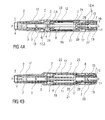
- FIGS 1a and 1b show two longitudinal sections of an auto-injector 1 in different section planes, the different section planes approximately 90° rotated to each other, wherein the auto-injector 1 is in an initial state prior to starting an injection.
- the auto-injector 1 comprises a chassis 2.
- the chassis 2 is generally considered as being fixed in position so motion of other components is described relative to the chassis 2.
- a syringe 3, e.g. a Hypak syringe, with a hollow injection needle 4 is arranged in a proximal part of the auto-injector 1.
- a protective needle sheath 5 is attached to the needle 4.
- a stopper 6 is arranged for sealing the syringe 3 distally and for displacing a liquid medicament M through the hollow needle 4.
- the syringe 3 is held in a tubular carrier 7 and supported at its proximal end therein.
- the carrier 7 is slidably arranged in the chassis 2.
- a drive spring 8 in the shape of a compression spring is arranged in a distal part of the carrier 7.
- a plunger 9 serves for forwarding the force of the drive spring 8 to the stopper 6.
- the drive spring 8 is loaded between a distal carrier end face 10 of the carrier 7 and a thrust face 11 arranged distally on the plunger 9.
- the carrier 7 is a key element housing the syringe 3, the drive spring 8 and the plunger 9, which are the components required to expel the medicament M from the syringe 3. These components can therefore be referred to as a drive sub-assembly.
- the chassis 2 and the carrier 7 are arranged within a tubular case 12.
- a trigger button 13 is arranged at a distal end of the case 12.
- a peg 14 protrudes from a distal end face of the trigger button 13 in the proximal direction P between two resilient arms 15 originating from the distal carrier end face 10 thus preventing them from flexing towards each other in an initial state A illustrated in figure 15A .
- FIG 15A only one of the resilient arms 15 is shown to illustrate the principle.
- the resilient arms 15 are caught in respective first recesses 16 in a distal plunger sleeve 17 attached distally to the thrust face 11 and arranged inside the drive spring 8.
- the engagement of the resilient arms 15 in the first recesses 16 prevents axial translation of the plunger 9 relative to the carrier 7.
- the resilient arms 15 are ramped in a manner to flex them inwards on relative motion between the plunger 9 and the carrier 7 under load of the drive spring 8, which is prevented by the peg 14 in the initial state A.
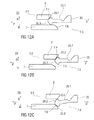
- the carrier 7 is locked to the chassis 2 for preventing relative translation by a detent mechanism 18 illustrated in more detail in figures 11A to 11D .
- the trigger button 13 is initially engaged to the case 12 by a button release mechanism 26 and cannot be depressed.
- the button release mechanism 26 is illustrated in detail in figures 16A to 16C .
- the button release mechanism 26 comprises a resilient proximal beam 13.1 on the trigger button 13, the proximal beam 13.1 having an outward first ramp 13.2 and an inward second ramp 13.3.
- the outward first ramp 13.2 is engaged in a ramped first case detent 12.1 preventing the trigger button 13 from moving out of the distal end D.
- the trigger button 13 proximally abuts both the case 12 and the carrier 7 hence being prevented from being depressed in the proximal direction P.
- a control spring 19 in the shape of another compression spring is arranged around the carrier 7 and acts between a proximal first collar 20 and a distal second collar 21.
- the control spring 19 is used to move the carrier 7 and hence the drive sub-assembly in the proximal direction P for needle extension or in the distal direction D for needle retraction.
- a cap 22 is attached to the proximal end of the case 12 and the protective needle sheath 5 is still in place over the needle 4 and the needle hub.
- An inner sleeve 22.1 of the cap 22 is arranged inside the chassis 2 and over the protective needle sheath 5.
- a barb 23 is attached in the inner sleeve 22.1 . The barb 23 is engaged to the protective needle sheath 5 for joint axial translation.
- a sequence of operation of the auto-injector 1 is as follows:
- the user grabs the case 12 and places the chassis 2 protruding from the case 12 at the proximal end P against an injection site, e.g. a patient's skin.
- an injection site e.g. a patient's skin.
- the case 12 translates in the proximal direction P relative to the chassis 2 into an advanced position as illustrated in figures 3A and 3B .
- the second collar 21 is locked to the case 12 and is moved with the case 12 relative to the chassis 2 and relative to nearly all other components of the auto-injector 1 thus slightly compressing the control spring 19 against the first collar 20 which is prevented from moving in the proximal direction P by the chassis 2 due to a needle extension control mechanism 24 being in a state A illustrated in detail in figure 12A .
- a resilient member in the shape of an arrowhead 20.1 is proximally arranged on the first collar 20. The first collar 20 with the arrowhead 20.1 is being forced in the proximal direction P under load of the compressed control spring 19.
- An outward sixth ramp 20.2 on the arrowhead 20.1 interacts with a second distal seventh ramp 2.4 on the chassis 2 ramping the arrowhead 20.1 in an inward direction I which is prevented by the arrowhead 20.1 inwardly abutting the carrier 7. Hence, the first collar 20 cannot translate in the proximal direction P.
- the second collar 21 is locked to the case due to a syringe retraction control mechanism 25 being in a state A illustrated in detail in figure 13A .
- the syringe retraction control mechanism 25 comprises a resilient proximal beam 21.1 on the second collar 21, the proximal beam 21.1 having a second beam head 21.2 having an inward boss 21.3 and a distal outward eighth ramp 21.4.
- the distal outward eighth ramp 21.4 is engaged in a ramped second case detent 12.2 in a manner ramping the second beam head 21.1 in the inward direction I with the second collar 21 under load of the control spring 19 in the distal direction D which is prevented by the inward boss 21.3 inwardly abutting the carrier 7.
- the control spring 19 expands returning the auto-injector 1 to the initial condition after removal of the cap 22 as illustrated in figures 2A and 2B .
- the ramp on the first case detent 12.1 interacts with the outward first ramp 13.2 on the proximal beam 13.1 on the trigger button 13 deflecting the proximal beam 13.1 in the inward direction I thus engaging the inward second ramp 13.3 on the proximal beam 13.1 in a ramped carrier detent 7.4 arranged in the carrier 7.
- the case 12 is translated further in the proximal direction P it supports the proximal beam 13.1 outwardly thus locking the trigger button 13 to the carrier 7.
- the trigger button 13 now protrudes from the distal end D of the chassis 12 and is ready to be pressed.
- the user depresses the trigger button 13 in the proximal direction P.
- the carrier 7 As the trigger button 13 abuts against the carrier 7 the carrier 7 is pushing in the proximal direction P against the chassis 2, the carrier 7 and the chassis 2 interacting in the detent mechanism 18.
- the force exerted by the user pressing the trigger button 13 is resolved through the chassis 2 onto the injection site, not between the trigger button 13 and the case 12.
- the detent mechanism 18 provides a resistive force when the user pushes the trigger button 13. Once the user applies a force which exceeds a pre-determined value the detent mechanism 18 releases, initiating the injection cycle.
- the resilient beam 2.1 on the chassis 2 begins to bow under load from the rhomboid ramp member 7.1 on the carrier 7, storing elastic energy.
- the proximal fourth ramp 7.2 on the ramp member 7.1 friction between the contacting faces of the first beam head 2.2 and the proximal fourth ramp 7.2 prevents movement of the first beam head 2.2 in the outward direction O until the straightening force in the resiliently deformed beam 2.1 is sufficiently large to overcome it.
- the resilient beam 2.1 is deflected in the outward direction O moving out of the way of the carrier 7 thus allowing the carrier 7 to translate in the proximal direction P.
- the needle extension control mechanism 24 is switched to a state B as illustrated in figure 12B .
- the carrier 7 has been translated in the proximal direction P in such a manner that the arrowhead 20.1 on the first collar 20 is no longer inwardly supported. This may be achieved by a second recess 7.5 in the carrier 7.
- the arrowhead 20.1 is now deflected in the inward direction I into the second recess 7.5 under load of the control spring 19 arriving at a state C as illustrated in figure 12C .
- the first collar 20 is now decoupled from the chassis 2.
- the arrowhead 20.1 couples the first collar 20 to the carrier 7 by an inward ninth ramp 20.3 engaging a distal tenth ramp 7.6 on the carrier 7 at the proximal end of the second recess 7.5.
- the control spring 19 continues moving the carrier 7 in the proximal direction P from this point. Whilst the user advances the needle 4 by a proportion of its travel, the control spring 19 takes over insertion before the needle 4 protrudes from the proximal end P. Therefore the user experience is that of pressing a button, rather than manually inserting a needle.
- the detent mechanism 18 relies on the user applying a force rather than a displacement. Once the force applied exceeds the force required to switch the detent the user will push the trigger button 13 fully, ensuring that the first collar 20 will always switch. If the user fails to pass the detent, the trigger button 13 returns to its unused state ready for use as illustrated in figures 3A and 3B . This feature avoids the auto-injector 1 arriving in an undefined state.
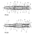
- Figures 4A and 4B show the auto-injector 1 with the trigger button 13 depressed sufficiently for the control spring 19 to couple on to the carrier 7 and continue moving the carrier 7 forwards, but not yet abutting the case 12.
- the carrier 7 coupled to the first collar 20 is translated in the proximal direction P driven by the control spring 19.
- the syringe 3 and needle 4 are also translated resulting in the needle 4 protruding from the proximal end P and being inserted into the injection site.
- the trigger button 13 returns to its initial position relative to the case 12 and latches back to the case 12 from the carrier 7 as in state A in figure 16A .
- the carrier 7 translates further in the proximal direction P preventing inward deflection of the proximal beam 13.1 so the outward first ramp 13.2 cannot disengage from the first case detent 12.1.
- the plunger release mechanism 27 arrives in a state B shown in figure 15B with the resilient arms 15 no longer inwardly supported by the peg 14. Due to the ramped engagement of the resilient arms 15 in the first recess 16 they are deflected in the inward direction I under load of the drive spring 8 arriving in a state B illustrated in figure 15C . Hence, the plunger 9 is released from the carrier 7 and driven in the proximal direction P by the drive spring 8, ready to expel the medicament M.
- the force to pull the peg 14 out from between the resilient arms 15 is provided by the control spring 19 while the force required to deflect the resilient arms 15 out of engagement to the plunger 9 is provided by the drive spring 8.
- the needle 4 is now fully inserted into the injection site as illustrated in figures 6A and 6B .
- the time between the trigger button 13 pressed and the needle 4 being fully inserted is very short, however several mechanical operations take place in this time.
- the needle extension depth is defined by the carrier 7 relative to the chassis 2 not relative to the case 12, so if the user flinches or fails to hold the auto-injector 1 hard against the skin, only the case 12 will move in the distal direction D while the injection depth remains constant.
- the feedback component 28 comprises an elongate portion 28.1 arranged within the distal plunger sleeve 17 and a distal end plate 28.2 arranged between the carrier end face 10 and an end face of the trigger button 13.
- Two second resilient arms 30 originate from the distal carrier end face 10 and extend in the proximal direction P.
- a feedback spring 29 is arranged to bias the feedback component 28 in the distal direction D relative to the carrier 7 by proximally bearing against a rib on the second resilient arms 30 and distally against the feedback component 28 (not illustrated).
- the feedback component 28 is not illustrated in figures 16A , B and C for clarity since it does not affect the function of the button release mechanism 26.
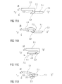
- a feedback release mechanism 31 for releasing the feedback component 28 is schematically illustrated in figures 14A, 14B and 14C .
- the feedback release mechanism 31 comprises the second resilient arms 30.
- a ramped inward boss 30.1 is arranged on each second resilient arm 30 which is engaged to a respective outward eleventh ramp 28.3 on the elongate portion 28.1 of the feedback component 28 in such a manner that the second resilient arm 30 is deflected in the outward direction O under load of the feedback spring 29.
- the second resilient arms 30 are prevented from being outwardly deflected by outward support of the distal plunger sleeve 17 thus preventing translation of the feedback component 28 relative to the carrier 7.
- the feedback release mechanism 31 remains in state A until immediately prior to fully expelling the medicament with the stopper 6 having almost bottomed out in the syringe 3 as illustrated in figures 7A and 7B .
- the plunger 9 has been translated in the proximal direction P relative to the carrier 7 to such an extent that the second resilient arms 30 are no longer supported by the distal plunger sleeve 17.
- the feedback release mechanism 31 has thus arrived in a state B illustrated in figure 14B .
- the second resilient arm 30 is outwardly deflected under load of the feedback spring 29 thus disengaging the feedback component 28 from the carrier 7 and allowing the feedback component 28 to move in the distal direction D driven by the feedback spring 29 in a state C illustrated in figure 14C .
- the feedback component 28 is accelerated in the distal direction D and the distal end plate 28.2 impacts on the inside of the trigger button 13 producing audible and tactile feedback to the user that expelling the medicament is about finished.
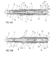
- Figures 8A and 8B show the auto-injector 1 with the stopper 6 having entirely bottomed out in the syringe 3.
- FIGS 9A and 9B show the auto-injector 1 with the chassis extended, e.g. when lifted from the injection site with the case 12 moved all the way in the distal direction D so that the chassis 2 protrudes from the proximal end of the case 12.
- the first collar 20 releases the carrier 7 and then the second collar 21 releases from the case 12 and pulls the carrier 7 in the distal direction D.
- the sequencing of this switching is critical as retraction will fail if both collars 20, 21 are attached to the carrier 7 at the same time. This is overcome by separating the switching of the collars 20, 21 by a significant displacement of the case 12.
- FIG. 12E The switching of the first collar 20 is illustrated in figures 12E and F .
- the case 12 has been allowed to move in the distal direction D under load of the control spring 19, e.g. during removal of the auto-injector 1 from the injection site.
- the first rib 12.3 (not illustrated, see figure 9A ) is removed from outwardly behind the arrowhead 20.1.
- the first collar 20 is still being pushed in the proximal direction P by the control spring 19.
- the syringe retraction control mechanism 25 switches from its state A (cf. figure 13A ) into a state B illustrated in figure 13B .
- the case 12 and the second collar 21 locked to the case 12 move together in the distal direction D while the carrier 7 is held in place by the detent mechanism 18 in its state C as described above (cf. figure 11C ). Due to this motion the inward boss 21.3 on the second beam head 21.2 of the proximal beam 21.1 on the second collar 21 no longer inwardly abuts the carrier 7.
- the detent mechanism 18 applies a small retarding force to the movement of the carrier 7 before the syringe retraction control mechanism 25 switches to state C as there is a small sliding force, applied by the second collar 21, pulling the carrier 7 in the distal direction D on translation of the case 12 in the distal direction D when the needle extension control mechanism 24 has already been switched into state E. If the carrier 7 moves too far in the distal direction D before the second collar 21 switches, the case 12 runs out of travel before the inward boss 21.3 can deflect into the third recess 7.7 preventing retraction.
- the carrier 7 and hence the rhomboid ramp member 7.1 are translated in the distal direction D under load of the control spring 19.
- the distal fifth ramp 7.3 of the rhomboid ramp member 7.1 engages the proximal third ramp 2.3 on the first beam head 2.2 of the resilient beam 2.1 in a manner deflecting the resilient beam 2.1 in the inward direction I. This applies the small retarding force to the movement of the carrier 7 required for ensuring the switching of the second collar 21 to the carrier 7.
- the resilient beam 2.1 and the rhomboid ramp member 7.1 are offset sideways to allow the resilient beam 2.1 to pass without contacting the rhomboid ramp member 7.1 as soon as the first beam head 2.2 is entirely inwardly from the ramp member 7.1 in a state D illustrated in figure 11D .
- the control spring 19 is grounded at its proximal end in the case by the first collar 20 being abutted against the chassis 2.
- the distal end of the control spring 19 moves the second collar 21 in the distal direction D taking with it the carrier 7 and hence the syringe 3 with the needle 4 overcoming the detent mechanism 18 as illustrated in figure 11D .
- the needle 4 is retracted by the auto-injector 1 as soon as the user allows the case 12 to translate sufficiently far as opposed to auto-injectors with needle shields which require the user to remove the auto-injector from the injection site thereby themselves pulling the needle out of the skin for allowing the needle shield to advance.
- the feedback spring 29 does not provide any retarding force. Once the feedback component 28 hits the trigger button 13 again on retraction of the carrier 7 the feedback spring 29 must be recompressed, reducing the force driving the final part of retraction. In order to ensure a reliable retraction despite this reducing force the control spring 19 must be appropriately dimensioned.
- the arrowhead 20.1 on the first collar 20 is inwardly supported by the carrier 7 in a state F illustrated in figure 12F and thus prevented from deflecting in the inward direction I.
- the outward sixth ramp 20.2 of the arrowhead 20.1 is engaged behind the first rib 12.3 on the case 12 preventing the case 12 from being pushed in the proximal direction P again.
- a clearance may be provided between the arrowhead 20.1 and the first rib 12.3 to allow for tolerances.
- the detent mechanism 18 returns to state A as in figure 11A locking the carrier 7 in position relative to the chassis 2 as it did initially, however it cannot be unlocked now as the case 12 cannot move relative to the chassis 2.
- a tab 20.4 on the first collar 20 is now visible through an indicator window 32 in the case 12 ⁇ indicating the auto-injector 1 has been used.
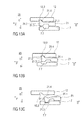
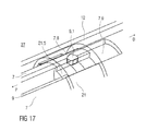
- Figure 17 is an isometric view of an alternative embodiment of the plunger release mechanism 27.
- the plunger release mechanism 27 prevents movement of the plunger 9 in the proximal direction P relative to the carrier 7 until the carrier 7 is moved in the proximal direction P for needle extension.
- the alternative embodiment of figure 17 releases the plunger 9 by movement of the carrier 7 relative to the second collar 21.
- Figure 17 illustrates the plunger release mechanism 27 prior to plunger release.
- the second collar 21 is shown transparent to improve clarity.
- the plunger 9 is being pushed in the proximal direction P by the drive spring 8.
- the plunger 9 In order for the plunger 9 to advance, it must rotate around a twelfth ramp 7.8 on the carrier 7. A ramp member 9.1 on the plunger 9 is arranged to engage this twelfth ramp 7.8. Rotation of the ramp member 9.1 is blocked by an inward longitudinal rib 21.5 on the second collar 21 splined in a longitudinal aperture 7.9 in the carrier 7. The case 12 and the second collar 21 remain in the same position, i.e. coupled to each other for joint axial translation. On depression of the trigger button 13 the carrier 13 and the plunger 9 being part of the drive sub-assembly are moved in the proximal direction P, first by the user pressing the trigger button 13 and then by the control spring 19 taking over via the first collar 20 as described above.
- the ramp member 9.1 on the collar 9 comes clear of the longitudinal rib 21.5 on the second collar 21 and can rotate past the proximal end of the longitudinal rib 21.5 due to its ramped engagement to the twelfth ramp 7.8 under load of the drive spring 8.
- the drive spring 8 advances the plunger 9 in the proximal direction P for expelling the medicament M.
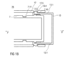
- Figure 18 is a longitudinal section of an alternative embodiment of the button release mechanism 26.
- the button release mechanism 26 of figure 16 which gives the appearance of a revealing trigger button 13 on skin contact by switching the ground of the trigger button 13 between the carrier 7 and the case 12, the button release mechanism 26 of figure 18 starts with the trigger button 13 locked but protruding from the distal end of the case 12.
- the trigger button 13 has two proximal beams 13.1, each of them having a ramped outward boss 13.4.
- the ramped outward bosses 13.4 are engaged in respective fourth recesses 12.5 in the case 12.
- Disengaging the ramped outward bosses 13.4 from the fourth recesses 12.5 is prevented by the carrier 7 inwardly supporting the proximal beams 13.1 in a manner to keep the proximal beams 13.1 from deflecting inwardly.
- Inward protrusions 13.5 on the proximal beams 13.1 abut against a second rib 7.10 on the carrier 7 in a manner preventing the carrier 7 from moving further in the proximal direction P in the initial state.
- a first window 7.11 in the carrier 7 is moved behind the inward protrusion 13.5 so as to allow the proximal beams 13.1 to be inwardly deflected due to their ramped engagement in the fourth recesses 12.5 on depression of the trigger button 13.
- the proximal beams 13.1 are now outwardly supported by the case 12 and remain engaged to the carrier 7 even on retraction of the needle 4.
- the trigger button 13 does therefore not return to its initial position, indicating that the auto-injector 1 has been used.
- the button release mechanism 26 illustrated in figure 18 may preferably be combined with the plunger release mechanism 27 illustrated in figure 17 .
- Figures 19A and 19B show two longitudinal sections of an alternative embodiment of the detent mechanism 18.
- the detent mechanism 18 of figures 11A to 11D which may be referred to as a "race track" mechanism because of the first beam head 2.2 travelling around the rhomboid ramp member 7.1 has multiple functions which control the movement of the carrier 7 relative to the chassis 2.
- the alternative detent mechanism 18 of figures 19A and 19B uses three clips 7.12, 7.13, 2.6 to produce the same effect.
- the first clip 7.12 is arranged as an outwardly biased resilient beam on the carrier 7 extending from the carrier 7 in the proximal direction P.
- the first clip 7.12 is arranged to prevent the carrier 7 from being moved in the proximal direction P prior to the chassis 2 being depressed or rather the case 12 being translated on skin contact.
- the first clip 7.12 is composed of two sections side by side. A first section 7.14 prevents movement of the carrier 7 in the proximal direction P by abutting the chassis 2 in a recess.
- a second section 7.15 is arranged as an outwardly protruding clip head arranged to be ramped inwards by a ramp feature 12.6 on the chassis 12 for releasing the first clip 7.12 thereby unlocking the carrier 7 from the chassis 2 when the case 12 is being translated in the proximal direction P on skin contact.
- a longitudinal slot 2.7 in the chassis 2 is arranged for allowing the second section 7.15 to slide in the proximal direction P once the lock has been released.
- a slight friction force between the first clip 7.12 and the chassis 2 provides the retarding force required to ensure retraction.
- the second clip 7.13 is arranged as a resilient beam on the carrier 7 extending in the distal direction D having an outwardly protruding third beam head 7.16 with a proximal ramp.
- the third beam head 7.16 serves as a back stop against a third rib 2.9 on the chassis 2 for preventing the carrier 7 moving in the distal direction D from its initial position.
- the carrier 7 and chassis 2 are assembled with the second clip 7.13 in this position prior to inserting the syringe 3 into the carrier 7 which is facilitated by the proximal ramp on the third beam head 7.16.
- the syringe 3 locks the clip in place by preventing inward deflection thus creating a fixed stop.
- the third clip 2.6 is a resilient beam on the chassis 2 extending in the distal direction D.
- a ramped fourth beam head 2.8 on the third clip 2.6 is arranged to inwardly engage in a fifth recess 7.17 in the carrier 7.
- Figure 20 is a longitudinal section of a third embodiment of the detent mechanism 18 which is a variation on the embodiment of figures 19A and 19B .
- the detent function of the third clip 2.6 has been added into the first clip 7.12.
- the lock between the case 12 and the carrier 7 is released in the same way, but the detent is provided by deflecting the first clip 7.12 inwards a second level which is achieved by the chassis 2 not having a slot 2.7 for the second section 7.15.
- the second section 7.15 once ramped inwards by the ramp feature 12.6 on the case 12 has to be further ramped inwards inside the chassis 2 on axial load between the chassis 2 and the carrier 7, suddenly releasing their engagement.
- Figure 21 is a longitudinal section of an alternative embodiment of the feedback release mechanism 31.
- the feedback spring 29 acts between the carrier 7 and the feedback component 28.
- the feedback spring 29 acts between the case 12 and the feedback component 28.
- the feedback spring 29 is compressed as the feedback component 28 moves with the carrier 7 relative to the case 12.
- the feedback component 28 moves in the distal direction D and impacts the trigger button 13.
- the feedback spring 29 is not being recompressed during needle retraction since it is grounded in the case 12 not in the carrier 7.
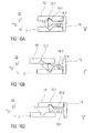
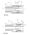
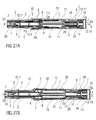
- Figures 22A and 22B show longitudinal sections of an alternative embodiment of the needle extension control mechanism 24 which is also arranged to perform the detent function of the detent mechanism 18 on needle retraction and needle extension.
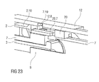
- Figure 23 shows a corresponding isometric view.
- a fourth clip 20.5 on the first collar 20 is arranged as a resilient beam with a beam head having an inward proximal thirteenth ramp 20.6 for engaging a fourth rib 7.18 on the carrier 7 and outwardly supported by the case 12 so as to keep the first collar 20 engaged to the carrier 7 prior to use, during needle extension and during expelling the medicament.
- the case 12 moves in distal direction relative to the carrier, e.g.
- a fifth clip 2.10 on the chassis 2 abuts a block 20.7 on the first collar 20 prior to use preventing the first collar 20 and hence the carrier 7 engaged to the first collar 20 from moving in the proximal direction P.
- the fifth clip 2.10 In order to release, the fifth clip 2.10 must be deflected outwards and over the block 20.7. Outward deflection of the fifth clip 2.10 is initially prevented by the case 12. Once the case 12 has moved on skin contact a second window 12.8 in the case 12 appears outwardly from the fifth clip 2.10 allowing outward deflection.
- the fifth clip 2.10 is then deflected by a fourteenth ramp 7.19 on the carrier 7 when the carrier 7 is pushed in the proximal direction P on button depression as the fourth clip 20.5 does allow translation of the carrier 7 in the proximal direction P relative to the first collar 20 but not the other way round.
- the detent for needle extension is provided by having to deflect the fifth clip 2.10 when it is loaded by the control spring 19.
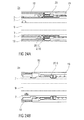
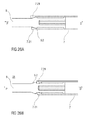
- Figures 24A and 24B show longitudinal sections of a third embodiment of the needle extension control mechanism 24, also arranged to perform the functions of the detent mechanism 18.
- Figure 25 is an isometric view of the needle extension control mechanism 24 of figure 24 .
- the embodiment is similar to that illustrated in figures 22A, 22B and 23 .
- the difference is that the fifth clip 2.10 is arranged on the first collar 20 and the block 20.7 is arranged on the chassis 2, i.e. their position has been switched, so there are two clips 2.10 and 20.5 on the first collar 20.
- the fourth clip 20.5 is identical to that in figure 22B . It keeps the first collar 20 connected to the carrier 7 until the needle retraction is triggered, ensuring full needle extension length or depth is reached and maintained until the retraction cycle is initiated by displacing the case backwards in distal direction relative to the chassis, e.g. when removing the auto-injector 1 from the skin.
- the fifth clip 2.10 provides the detent for needle extension and releases the first collar 20 from the chassis 2, initiating needle extension.
- the fifth clip 2.10 prevents the first collar 20 and hence the carrier 7 engaged to the first collar 20 from moving in the proximal direction P prior to use by abutting the block 20.7 on the chassis 2.
- the fifth clip 2.10 In order to release, the fifth clip 2.10 must be deflected outwards and over the block 20.7. Outward deflection of the fifth clip 2.10 is initially prevented by the case 12. Once the case 12 has moved on skin contact the second window 12.8 in the case 12 appears outwardly from the fifth clip 2.10 allowing outward deflection.
- the fifth clip 2.10 is then deflected by the fourteenth ramp 7.19 on the carrier 7 when the carrier 7 is pushed in the proximal direction P on button depression as the fourth clip 20.5 does allow translation of the carrier 7 in the proximal direction P relative to the first collar 20 but not the other way round.
- the detent for needle extension is provided by having to deflect the fifth clip 2.10 when it is loaded by the control spring 19.
- Figures 26A and 26B show a longitudinal section of a third embodiment of the feedback release mechanism 31.
- the plunger 9 comprises a proximally ramped rib 9.2 arranged to splay two seventh clips 7.21 on the carrier 7 immediately prior to the end of dose. When the proximally ramped rib 9.2 has travelled past the seventh clips 7.21 they snap back and impact the plunger 9 generating a sound.
- the tubular shape of the carrier 7 helps to transmit the sound.
- Figure 26A shows the feedback release mechanism 31 before release.
- Figure 26B shows the feedback release mechanism 31 after release. Proximal faces of the seventh clips 7.21 on the carrier 7 are axially offset to facilitate assembly by lifting the seventh clips 7.21 over the distal side of the proximally ramped rib 9.2 one by one.
- Figures 27A and 27B show longitudinal sections of another embodiment of the auto-injector 1 in different section planes, the different section planes approximately 90° rotated to each other, wherein the auto-injector 1 is in an initial state prior to use.
- the auto-injector 1 is essentially identical to the one described in figures 1 to 16 .
- the auto-injector 1 of this embodiment has a wrap-over sleeve trigger instead of a trigger button.
- the wrap-over sleeve trigger 12 is the same component as the case 12 which has a closed distal end face 12.10 other than the one in figures 1 to 16 .
- An internal trigger button 13 is arranged at the distal end inside the sleeve trigger 12. Other than in figures 1 to 16 the trigger button 13 is not visible nor does it protrude from the case 12 in any state. In the initial state a clearance 33 is provided between the distal end face 12.10 of the sleeve trigger 12 and the internal trigger button 13 allowing for some travel of the sleeve trigger 12 without interfering with the trigger button 13.
- the detent mechanism 18 is arranged to provide a resistive force when the user reaches the second phase of sleeve travel. Internally, there is no difference to the embodiment of figures 1 to 16 at this point.
- Needle extension is triggered by the user fully advancing the sleeve trigger 12 in the second phase of sleeve travel thereby fully depressing the internal trigger button 13 and overcoming the detent mechanism as in the embodiment of figures 1 to 16 .
Priority Applications (26)
| Application Number | Priority Date | Filing Date | Title |
|---|---|---|---|
| EP11155032A EP2489381A1 (en) | 2011-02-18 | 2011-02-18 | Auto-injector |
| PL12705108T PL2675506T3 (pl) | 2011-02-18 | 2012-02-16 | Autoiniektor |
| MX2013009169A MX2013009169A (es) | 2011-02-18 | 2012-02-16 | Auto - inyector. |
| PCT/EP2012/052640 WO2012110573A1 (en) | 2011-02-18 | 2012-02-16 | Auto-injector |
| DK12705108.4T DK2675506T3 (en) | 2011-02-18 | 2012-02-16 | autoinjector |
| SG2013059647A SG192633A1 (en) | 2011-02-18 | 2012-02-16 | Auto-injector |
| AU2012217077A AU2012217077B2 (en) | 2011-02-18 | 2012-02-16 | Auto-injector |
| KR1020137024735A KR20140015379A (ko) | 2011-02-18 | 2012-02-16 | 자동 주사기 |
| NZ614081A NZ614081B2 (en) | 2011-02-18 | 2012-02-16 | Auto-injector |
| ARP120100521A AR085256A1 (es) | 2011-02-18 | 2012-02-16 | Mecanismo de retencion |
| ES12705108.4T ES2548175T3 (es) | 2011-02-18 | 2012-02-16 | Auto-inyector |
| HUE12705108A HUE025404T2 (en) | 2011-02-18 | 2012-02-16 | Automatic syringe |
| TW101105004A TWI551317B (zh) | 2011-02-18 | 2012-02-16 | 自動注射器(一) |
| MYPI2013002876A MY166814A (en) | 2011-02-18 | 2012-02-16 | Auto-injector |
| ARP120100520A AR085255A1 (es) | 2011-02-18 | 2012-02-16 | Auto-inyector |
| JP2013553927A JP6027984B2 (ja) | 2011-02-18 | 2012-02-16 | 自動注射器 |
| EP12705108.4A EP2675506B1 (en) | 2011-02-18 | 2012-02-16 | Auto-injector |
| BR112013020900A BR112013020900A2 (pt) | 2011-02-18 | 2012-02-16 | autoinjetor |
| US13/983,808 US9656021B2 (en) | 2011-02-18 | 2012-02-16 | Auto-injector |
| CN201280019040.XA CN103476445B (zh) | 2011-02-18 | 2012-02-16 | 自动注射装置 |
| CA2826344A CA2826344A1 (en) | 2011-02-18 | 2012-02-16 | Auto-injector |
| RU2013142424/14A RU2585157C2 (ru) | 2011-02-18 | 2012-02-16 | Автоинъектор |
| IL227727A IL227727A0 (en) | 2011-02-18 | 2013-07-30 | self-injector |
| ZA2013/05842A ZA201305842B (en) | 2011-02-18 | 2013-08-02 | Auto-injector |
| HK14101345.4A HK1188163A1 (en) | 2011-02-18 | 2014-02-13 | Auto-injector |
| US15/480,026 US10556064B2 (en) | 2011-02-18 | 2017-04-05 | Auto-injector |
Applications Claiming Priority (1)
| Application Number | Priority Date | Filing Date | Title |
|---|---|---|---|
| EP11155032A EP2489381A1 (en) | 2011-02-18 | 2011-02-18 | Auto-injector |
Publications (1)
| Publication Number | Publication Date |
|---|---|
| EP2489381A1 true EP2489381A1 (en) | 2012-08-22 |
Family
ID=49080497
Family Applications (2)
| Application Number | Title | Priority Date | Filing Date |
|---|---|---|---|
| EP11155032A Ceased EP2489381A1 (en) | 2011-02-18 | 2011-02-18 | Auto-injector |
| EP12705108.4A Active EP2675506B1 (en) | 2011-02-18 | 2012-02-16 | Auto-injector |
Family Applications After (1)
| Application Number | Title | Priority Date | Filing Date |
|---|---|---|---|
| EP12705108.4A Active EP2675506B1 (en) | 2011-02-18 | 2012-02-16 | Auto-injector |
Country Status (22)
| Country | Link |
|---|---|
| US (2) | US9656021B2 (ko) |
| EP (2) | EP2489381A1 (ko) |
| JP (1) | JP6027984B2 (ko) |
| KR (1) | KR20140015379A (ko) |
| CN (1) | CN103476445B (ko) |
| AR (1) | AR085255A1 (ko) |
| AU (1) | AU2012217077B2 (ko) |
| BR (1) | BR112013020900A2 (ko) |
| CA (1) | CA2826344A1 (ko) |
| DK (1) | DK2675506T3 (ko) |
| ES (1) | ES2548175T3 (ko) |
| HK (1) | HK1188163A1 (ko) |
| HU (1) | HUE025404T2 (ko) |
| IL (1) | IL227727A0 (ko) |
| MX (1) | MX2013009169A (ko) |
| MY (1) | MY166814A (ko) |
| PL (1) | PL2675506T3 (ko) |
| RU (1) | RU2585157C2 (ko) |
| SG (1) | SG192633A1 (ko) |
| TW (1) | TWI551317B (ko) |
| WO (1) | WO2012110573A1 (ko) |
| ZA (1) | ZA201305842B (ko) |
Cited By (1)
| Publication number | Priority date | Publication date | Assignee | Title |
|---|---|---|---|---|
| CN105636623A (zh) * | 2013-08-01 | 2016-06-01 | 椭元医疗技术有限公司 | 药物输送装置 |
Families Citing this family (46)
| Publication number | Priority date | Publication date | Assignee | Title |
|---|---|---|---|---|
| EP2195052B1 (en) | 2007-10-02 | 2019-09-04 | Medimop Medical Projects Ltd. | External drug pump |
| EP2399635A1 (en) | 2010-06-28 | 2011-12-28 | Sanofi-Aventis Deutschland GmbH | Auto-injector |
| EP2438944A1 (en) * | 2010-10-08 | 2012-04-11 | Sanofi-Aventis Deutschland GmbH | Auto-injector |
| EP2489389A1 (en) | 2011-02-18 | 2012-08-22 | Sanofi-Aventis Deutschland GmbH | Detent mechanism |
| EP2489388A1 (en) | 2011-02-18 | 2012-08-22 | Sanofi-Aventis Deutschland GmbH | Auto-injector |
| EP2489385A1 (en) | 2011-02-18 | 2012-08-22 | Sanofi-Aventis Deutschland GmbH | Auto-injector |
| EP2489382A1 (en) | 2011-02-18 | 2012-08-22 | Sanofi-Aventis Deutschland GmbH | Auto-injector |
| EP2489384A1 (en) | 2011-02-18 | 2012-08-22 | Sanofi-Aventis Deutschland GmbH | Auto-injector |
| EP2489386A1 (en) | 2011-02-18 | 2012-08-22 | Sanofi-Aventis Deutschland GmbH | Auto-injector |
| EP2489380A1 (en) | 2011-02-18 | 2012-08-22 | Sanofi-Aventis Deutschland GmbH | Injection device |
| EP2489390A1 (en) | 2011-02-18 | 2012-08-22 | Sanofi-Aventis Deutschland GmbH | Detent mechanism |
| EP2489387A1 (en) | 2011-02-18 | 2012-08-22 | Sanofi-Aventis Deutschland GmbH | Auto-injector |
| EP2489381A1 (en) | 2011-02-18 | 2012-08-22 | Sanofi-Aventis Deutschland GmbH | Auto-injector |
| EP3590568A1 (de) | 2013-03-22 | 2020-01-08 | TecPharma Licensing AG | Substanzabgabevorrichtung mit signalvorrichtung |
| EP2823841A1 (en) | 2013-07-09 | 2015-01-14 | Sanofi-Aventis Deutschland GmbH | Autoinjector |
| WO2015055588A1 (en) * | 2013-10-18 | 2015-04-23 | Sanofi-Aventis Deutschland Gmbh | Medicament delivery device with two drive springs |
| FR3016523B1 (fr) * | 2014-01-20 | 2017-08-11 | Biocorp Rech Et Dev | Injecteur automatique |
| EP2923714A1 (en) | 2014-03-28 | 2015-09-30 | Sanofi-Aventis Deutschland GmbH | Autoinjector triggered by skin contact |
| US20160144123A1 (en) * | 2014-11-26 | 2016-05-26 | John Berndt | Syringe adapter |
| GB2534599A (en) * | 2015-01-29 | 2016-08-03 | Owen Mumford Ltd | A medicament delivery device |
| EP3791919A1 (en) | 2015-03-10 | 2021-03-17 | Regeneron Pharmaceuticals, Inc. | Aseptic piercing system |
| GB2538486A (en) * | 2015-04-30 | 2016-11-23 | Owen Mumford Ltd | Injection Device |
| US10576207B2 (en) | 2015-10-09 | 2020-03-03 | West Pharma. Services IL, Ltd. | Angled syringe patch injector |
| CN108472438B (zh) | 2015-10-09 | 2022-01-28 | 西医药服务以色列分公司 | 至预填充的流体储存器的弯曲流体路径附加装置 |
| GB2545266B (en) | 2015-12-11 | 2018-08-08 | Oval Medical Tech Limited | Autoinjector with retracting needle |
| JP6814809B2 (ja) * | 2015-12-30 | 2021-01-20 | ノボ・ノルデイスク・エー/エス | 針シールド発動を有する自動注射器 |
| CN113041432B (zh) | 2016-01-21 | 2023-04-07 | 西医药服务以色列有限公司 | 包括视觉指示物的药剂输送装置 |
| US10646643B2 (en) | 2016-01-21 | 2020-05-12 | West Pharma. Services IL, Ltd. | Needle insertion and retraction mechanism |
| CN109219456B (zh) | 2016-01-21 | 2020-05-15 | 西医药服务以色列有限公司 | 自动注射器中的力牵制 |
| US11612700B2 (en) | 2016-02-29 | 2023-03-28 | Shl Medical Ag | Delivery device |
| US20170246400A1 (en) * | 2016-02-29 | 2017-08-31 | Shl Group Ab | Delivery Device |
| WO2017161076A1 (en) | 2016-03-16 | 2017-09-21 | Medimop Medical Projects Ltd. | Staged telescopic screw assembly having different visual indicators |
| WO2018026387A1 (en) | 2016-08-01 | 2018-02-08 | Medimop Medical Projects Ltd. | Anti-rotation cartridge pin |
| EP3503949A1 (en) | 2016-08-26 | 2019-07-03 | Sanofi-Aventis Deutschland GmbH | Audible indicator |
| JP6955010B2 (ja) * | 2016-08-30 | 2021-10-27 | サノフィ−アベンティス・ドイチュラント・ゲゼルシャフト・ミット・ベシュレンクテル・ハフツング | 注射デバイス |
| GB201616393D0 (en) * | 2016-09-27 | 2016-11-09 | Owen Mumford Ltd | Auto-injector |
| CN110248686B (zh) * | 2016-09-27 | 2022-04-29 | 赛诺菲-安万特德国有限公司 | 药剂递送装置 |
| FR3058895B1 (fr) * | 2016-11-23 | 2024-01-12 | Nemera La Verpilliere | Dispositif d'injection presentant un dispositif de retrait de capuchon de seringue ameliore |
| IL269571B (en) | 2017-05-05 | 2022-08-01 | Regeneron Pharma | Automatic injector |
| EP3630226A1 (en) | 2017-05-30 | 2020-04-08 | West Pharma. Services Il, Ltd. | Modular drive train for wearable injector |
| EP3524297A1 (en) * | 2018-02-12 | 2019-08-14 | Sanofi | Injector device |
| GB2577555A (en) | 2018-09-28 | 2020-04-01 | Owen Mumford Ltd | Injection device end of dose indicator |
| CN109331295B (zh) * | 2018-11-27 | 2024-04-19 | 甘肃成纪生物药业有限公司 | 一种注射笔 |
| WO2021162086A1 (ja) * | 2020-02-14 | 2021-08-19 | 大成化工株式会社 | 注射装置 |
| USD1007676S1 (en) | 2021-11-16 | 2023-12-12 | Regeneron Pharmaceuticals, Inc. | Wearable autoinjector |
| WO2024055268A1 (zh) * | 2022-09-16 | 2024-03-21 | 嘉兴森迈医疗科技有限公司 | 机械式自动注射笔 |
Citations (3)
| Publication number | Priority date | Publication date | Assignee | Title |
|---|---|---|---|---|
| US20020095120A1 (en) | 2000-08-29 | 2002-07-18 | Andre Larsen | Automatic injection device |
| US7749195B2 (en) * | 2003-09-11 | 2010-07-06 | Tecpharma Licensing Ag | Administration device with an insertion mechanism and a delivery mechanism |
| US20100292653A1 (en) * | 2007-09-25 | 2010-11-18 | Becton Dickinson France S.A.S. | Autoinjector with trigger positionable in active position by movement of a safety shield and indication of the active position |
Family Cites Families (78)
| Publication number | Priority date | Publication date | Assignee | Title |
|---|---|---|---|---|
| GB8926825D0 (en) | 1989-11-28 | 1990-01-17 | Glaxo Group Ltd | Device |
| US6287610B1 (en) | 1991-11-20 | 2001-09-11 | Monfort, Inc. | Method for increasing the tenderness of a meat product |
| US5681291A (en) | 1992-11-19 | 1997-10-28 | Tebro S.A. | Disposable auto-injector for prefilled syringes |
| US5320609A (en) | 1992-12-07 | 1994-06-14 | Habley Medical Technology Corporation | Automatic pharmaceutical dispensing syringe |
| US5599309A (en) | 1993-03-24 | 1997-02-04 | Owen Mumford Limited | Injection devices |
| US5478316A (en) | 1994-02-02 | 1995-12-26 | Becton, Dickinson And Company | Automatic self-injection device |
| WO1996027400A1 (en) | 1995-03-07 | 1996-09-12 | Eli Lilly And Company | Recyclable medication dispensing device |
| FR2733155B1 (fr) | 1995-04-18 | 1997-09-19 | Tebro | Auto-injecteur rechargeable |
| US5746215A (en) | 1996-11-01 | 1998-05-05 | U.S. Medical Instruments, Inc. | IV infusion or collection device with extendable and retractable needle |
| SE9803662D0 (sv) | 1998-10-26 | 1998-10-26 | Pharmacia & Upjohn Ab | Autoinjector |
| FR2787246B1 (fr) | 1998-12-09 | 2001-02-23 | Alpes Lasers | Laser de type semi-conducteur |
| JP5058425B2 (ja) | 2000-08-02 | 2012-10-24 | ベクトン・ディキンソン・アンド・カンパニー | ペン針および安全シールドシステム |
| RU2203688C2 (ru) * | 2000-08-30 | 2003-05-10 | Конструкторское бюро "Полет" ГУДП ГП "Производственное объединение "Полет" | Шприц |
| NZ539404A (en) | 2000-10-09 | 2007-05-31 | Lilly Co Eli | Pen device for administration of parathyroid hormone |
| PL360998A1 (en) | 2000-10-13 | 2004-09-20 | Alza Corporation | Apparatus and method for piercing skin with microprotrusions |
| SE518981C2 (sv) | 2000-12-14 | 2002-12-17 | Shl Medical Ab | Autoinjektor |
| US6461362B1 (en) | 2001-04-30 | 2002-10-08 | Mdc Investment Holdings, Inc. | Catheter insertion device with retractable needle |
| WO2004047892A1 (de) | 2002-11-25 | 2004-06-10 | Tecpharma Licensing Ag | Injektionsvorrichtung mit nadelschutz |
| GB0312852D0 (en) | 2003-06-05 | 2003-07-09 | Owen Mumford Ltd | Improvements relating to syringe firing mechanisms |
| US20050027255A1 (en) | 2003-07-31 | 2005-02-03 | Sid Technologies, Llc | Automatic injector |
| DE10351599A1 (de) | 2003-11-05 | 2005-06-16 | Tecpharma Licensing Ag | Autoinjektionsvorrichtung |
| US20050101919A1 (en) * | 2003-11-07 | 2005-05-12 | Lennart Brunnberg | Device for an injector |
| CH696421A5 (de) | 2003-12-18 | 2007-06-15 | Tecpharma Licensing Ag | Autoinjektor mit Arretierung des Wirkstoffbehälters. |
| GB2410188B (en) | 2004-01-23 | 2006-01-25 | Medical House Plc | Injection device |
| JP4578484B2 (ja) | 2004-01-23 | 2010-11-10 | ザ メディカルハウス リミテッド | 注射装置 |
| US20050222539A1 (en) | 2004-03-30 | 2005-10-06 | Pediamed Pharmaceuticals, Inc. | Automatic injection device |
| US7160219B2 (en) | 2004-06-03 | 2007-01-09 | Arvinmeritor Technology Llc. | Method and apparatus for lubricating a differential gear assembly |
| US9220595B2 (en) | 2004-06-23 | 2015-12-29 | Orthovita, Inc. | Shapeable bone graft substitute and instruments for delivery thereof |
| US8048035B2 (en) | 2004-08-06 | 2011-11-01 | Meridian Medical Technologies, Inc. | Automatic injector with needle cover |
| DE102004041151A1 (de) | 2004-08-25 | 2006-03-02 | Tecpharma Licensing Ag | Dosiervorrichtung mit Ablaufsteuerung |
| EP1814616A1 (en) | 2004-11-04 | 2007-08-08 | Sid Technologies Llc | Automatic injector |
| DE102004063647A1 (de) | 2004-12-31 | 2006-07-20 | Tecpharma Licensing Ag | Vorrichtung zur dosierten Verabreichung eines fluiden Produkts mit Kupplung |
| PL1877119T3 (pl) | 2005-01-25 | 2019-03-29 | Novo Nordisk A/S | Urządzenie do wstrzykiwania z mechanizmem zwrotnym informującym o końcu dawki |
| US7407494B2 (en) | 2005-01-31 | 2008-08-05 | Bostroem Anders | Device for delivering medicament |
| US8696625B2 (en) | 2005-04-20 | 2014-04-15 | Becton Dickinson France | Injection set and injection assistance device |
| CA2607383A1 (en) | 2005-05-16 | 2006-11-23 | Mallinckrodt Inc. | Radiopharmaceutical container having syringe capper |
| EP1893256B1 (en) | 2005-06-16 | 2012-09-26 | Novo Nordisk A/S | Method and apparatus for assisting patients in self administration of medication |
| WO2007002052A2 (en) | 2005-06-21 | 2007-01-04 | Eli Lilly And Company | Apparatus and method for injecting a pharmaceutical |
| DE202005010389U1 (de) | 2005-07-01 | 2005-09-08 | Tecpharma Licensing Ag | Magnetische Kolbenstangenrückführung und Kolbenstangenfixierung |
| DE102005052460A1 (de) | 2005-11-03 | 2007-05-16 | Tecpharma Licensing Ag | Autoinjektor - Ablaufsteuerung für Behältniswechsel |
| FR2899482A1 (fr) | 2006-04-11 | 2007-10-12 | Becton Dickinson France Soc Pa | Dispositif d'injection automatique |
| FR2905273B1 (fr) | 2006-09-06 | 2009-04-03 | Becton Dickinson France Soc Pa | Dispositif d'injection automatique avec moyen de temporisation. |
| GB2443606B (en) | 2006-11-13 | 2011-07-20 | Cilag Gmbh Int | Injection device |
| EP1932558B1 (en) | 2006-12-13 | 2011-06-29 | SHL Group AB | Auto-Injector |
| US20080228147A1 (en) | 2007-03-15 | 2008-09-18 | Bristol-Myers Squibb Company | Injector for use with pre-filled syringes and method of assembly |
| CN101678167B (zh) | 2007-03-22 | 2013-09-18 | 特克法马许可公司 | 注射装置中的弹簧机构 |
| DE102007013837A1 (de) | 2007-03-22 | 2008-09-25 | Tecpharma Licensing Ag | Federanordnung in einer Injektionsvorrichtung |
| DE102007013838A1 (de) | 2007-03-22 | 2008-09-25 | Tecpharma Licensing Ag | Injektionsvorrichtung mit zeitkonstantem Ausschüttsignal |
| EP2129415B1 (de) | 2007-03-22 | 2018-10-24 | Tecpharma Licensing AG | Injektionsvorrichtung mit gesteuertem nadelrückzug |
| DE102007016811A1 (de) * | 2007-04-05 | 2008-10-09 | Tecpharma Licensing Ag | Vorrichtung zur Verabreichung eines fluiden Wirkstoffes aus einer Mehrkammerampulle |
| US8057427B2 (en) | 2007-05-09 | 2011-11-15 | Meridian Medical Technologies, Inc. | Drug delivery system with a small amount of a therapeutic agent |
| DE102007030327A1 (de) | 2007-06-29 | 2009-01-02 | Tecpharma Licensing Ag | Injektionsvorrichtung mit einer Feder für eine Nadelschutzhülse |
| WO2009040602A1 (en) | 2007-09-25 | 2009-04-02 | Becton Dickinson France | Autoinject0r with deactivating means moveable by a safety shield |
| US8876779B2 (en) | 2007-11-12 | 2014-11-04 | Bang & Olufsen Medicom A/S | Auto injector with changing anchor locations for a mechanical driver |
| EP2237817B1 (en) | 2007-11-14 | 2019-02-13 | SHL Group AB | Automatic injection device with actively triggered syringe withdrawal |
| CN101903059B (zh) | 2007-12-20 | 2013-06-19 | 诺沃-诺迪斯克有限公司 | 用于输送固定剂量液态药物的注射装置 |
| GB0801874D0 (en) | 2008-02-01 | 2008-03-12 | Liversidge Barry P | Injection device |
| GB2460398A (en) | 2008-05-20 | 2009-12-02 | Owen Mumford Ltd | Auto-injector having a magnetic injection indicator and a needle sheath retainer |
| ES2677902T3 (es) * | 2008-09-29 | 2018-08-07 | Becton Dickinson France | Dispositivo de inyección automática |
| CN102209563B (zh) | 2008-09-29 | 2014-04-23 | 贝克顿迪金森法国公司 | 带有完成注射声响指示的自动注射装置 |
| GB2469672B (en) | 2009-04-23 | 2013-09-25 | Medical House Ltd | Improved autoinjector |
| US20100286612A1 (en) | 2009-05-06 | 2010-11-11 | William Cirillo | Medication injection supervisor device |
| WO2011043714A1 (en) | 2009-10-08 | 2011-04-14 | Shl Group Ab | Medicament delivery device |
| AU2011214922B2 (en) | 2010-02-09 | 2012-12-13 | Shl Medical Ag | Medicament delivery device |
| CN105327432B (zh) | 2010-03-31 | 2018-11-30 | Shl集团有限责任公司 | 包括反馈信号装置的药物输送设备 |
| EP2399635A1 (en) | 2010-06-28 | 2011-12-28 | Sanofi-Aventis Deutschland GmbH | Auto-injector |
| GB201021767D0 (en) | 2010-12-22 | 2011-02-02 | Owen Mumford Ltd | Autoinjectors |
| EP2489382A1 (en) | 2011-02-18 | 2012-08-22 | Sanofi-Aventis Deutschland GmbH | Auto-injector |
| EP2489381A1 (en) | 2011-02-18 | 2012-08-22 | Sanofi-Aventis Deutschland GmbH | Auto-injector |
| EP2489388A1 (en) | 2011-02-18 | 2012-08-22 | Sanofi-Aventis Deutschland GmbH | Auto-injector |
| EP2489387A1 (en) | 2011-02-18 | 2012-08-22 | Sanofi-Aventis Deutschland GmbH | Auto-injector |
| EP2489385A1 (en) | 2011-02-18 | 2012-08-22 | Sanofi-Aventis Deutschland GmbH | Auto-injector |
| EP2489386A1 (en) | 2011-02-18 | 2012-08-22 | Sanofi-Aventis Deutschland GmbH | Auto-injector |
| EP2489380A1 (en) | 2011-02-18 | 2012-08-22 | Sanofi-Aventis Deutschland GmbH | Injection device |
| EP2489389A1 (en) | 2011-02-18 | 2012-08-22 | Sanofi-Aventis Deutschland GmbH | Detent mechanism |
| EP2489383A1 (en) | 2011-02-18 | 2012-08-22 | Sanofi-Aventis Deutschland GmbH | Auto-injector |
| EP2489384A1 (en) | 2011-02-18 | 2012-08-22 | Sanofi-Aventis Deutschland GmbH | Auto-injector |
| EP2489390A1 (en) | 2011-02-18 | 2012-08-22 | Sanofi-Aventis Deutschland GmbH | Detent mechanism |
-
2011
- 2011-02-18 EP EP11155032A patent/EP2489381A1/en not_active Ceased
-
2012
- 2012-02-16 CA CA2826344A patent/CA2826344A1/en not_active Abandoned
- 2012-02-16 ES ES12705108.4T patent/ES2548175T3/es active Active
- 2012-02-16 AR ARP120100520A patent/AR085255A1/es not_active Application Discontinuation
- 2012-02-16 US US13/983,808 patent/US9656021B2/en active Active
- 2012-02-16 SG SG2013059647A patent/SG192633A1/en unknown
- 2012-02-16 EP EP12705108.4A patent/EP2675506B1/en active Active
- 2012-02-16 WO PCT/EP2012/052640 patent/WO2012110573A1/en active Application Filing
- 2012-02-16 MX MX2013009169A patent/MX2013009169A/es active IP Right Grant
- 2012-02-16 MY MYPI2013002876A patent/MY166814A/en unknown
- 2012-02-16 RU RU2013142424/14A patent/RU2585157C2/ru not_active IP Right Cessation
- 2012-02-16 TW TW101105004A patent/TWI551317B/zh not_active IP Right Cessation
- 2012-02-16 DK DK12705108.4T patent/DK2675506T3/en active
- 2012-02-16 PL PL12705108T patent/PL2675506T3/pl unknown
- 2012-02-16 HU HUE12705108A patent/HUE025404T2/en unknown
- 2012-02-16 KR KR1020137024735A patent/KR20140015379A/ko unknown
- 2012-02-16 CN CN201280019040.XA patent/CN103476445B/zh active Active
- 2012-02-16 BR BR112013020900A patent/BR112013020900A2/pt not_active IP Right Cessation
- 2012-02-16 JP JP2013553927A patent/JP6027984B2/ja active Active
- 2012-02-16 AU AU2012217077A patent/AU2012217077B2/en not_active Ceased
-
2013
- 2013-07-30 IL IL227727A patent/IL227727A0/en unknown
- 2013-08-02 ZA ZA2013/05842A patent/ZA201305842B/en unknown
-
2014
- 2014-02-13 HK HK14101345.4A patent/HK1188163A1/xx unknown
-
2017
- 2017-04-05 US US15/480,026 patent/US10556064B2/en active Active
Patent Citations (3)
| Publication number | Priority date | Publication date | Assignee | Title |
|---|---|---|---|---|
| US20020095120A1 (en) | 2000-08-29 | 2002-07-18 | Andre Larsen | Automatic injection device |
| US7749195B2 (en) * | 2003-09-11 | 2010-07-06 | Tecpharma Licensing Ag | Administration device with an insertion mechanism and a delivery mechanism |
| US20100292653A1 (en) * | 2007-09-25 | 2010-11-18 | Becton Dickinson France S.A.S. | Autoinjector with trigger positionable in active position by movement of a safety shield and indication of the active position |
Non-Patent Citations (1)
| Title |
|---|
| "Remington's Pharmaceutical Sciences", 1985, MARK PUBLISHING COMPANY |
Cited By (4)
| Publication number | Priority date | Publication date | Assignee | Title |
|---|---|---|---|---|
| CN105636623A (zh) * | 2013-08-01 | 2016-06-01 | 椭元医疗技术有限公司 | 药物输送装置 |
| US10207051B2 (en) | 2013-08-01 | 2019-02-19 | Oval Medical Technologies Limited | Drug delivery device |
| CN105636623B (zh) * | 2013-08-01 | 2019-06-11 | 椭元医疗技术有限公司 | 药物输送装置 |
| US11058820B2 (en) | 2013-08-01 | 2021-07-13 | Oval Medical Technologies Limited | Drug delivery device |
Also Published As
| Publication number | Publication date |
|---|---|
| TWI551317B (zh) | 2016-10-01 |
| US20130317479A1 (en) | 2013-11-28 |
| HK1188163A1 (en) | 2014-04-25 |
| US9656021B2 (en) | 2017-05-23 |
| JP2014507996A (ja) | 2014-04-03 |
| CN103476445B (zh) | 2016-03-09 |
| CA2826344A1 (en) | 2012-08-23 |
| NZ614081A (en) | 2014-11-28 |
| IL227727A0 (en) | 2013-09-30 |
| RU2585157C2 (ru) | 2016-05-27 |
| KR20140015379A (ko) | 2014-02-06 |
| EP2675506A1 (en) | 2013-12-25 |
| SG192633A1 (en) | 2013-09-30 |
| AU2012217077A1 (en) | 2013-09-05 |
| HUE025404T2 (en) | 2016-02-29 |
| BR112013020900A2 (pt) | 2016-09-27 |
| US20170246398A1 (en) | 2017-08-31 |
| DK2675506T3 (en) | 2015-09-28 |
| WO2012110573A1 (en) | 2012-08-23 |
| TW201302258A (zh) | 2013-01-16 |
| ES2548175T3 (es) | 2015-10-14 |
| EP2675506B1 (en) | 2015-06-24 |
| JP6027984B2 (ja) | 2016-11-16 |
| US10556064B2 (en) | 2020-02-11 |
| AR085255A1 (es) | 2013-09-18 |
| RU2013142424A (ru) | 2015-03-27 |
| AU2012217077B2 (en) | 2016-02-11 |
| ZA201305842B (en) | 2014-04-30 |
| MY166814A (en) | 2018-07-23 |
| MX2013009169A (es) | 2013-08-29 |
| PL2675506T3 (pl) | 2015-12-31 |
| CN103476445A (zh) | 2013-12-25 |
Similar Documents
| Publication | Publication Date | Title |
|---|---|---|
| US20240042137A1 (en) | Auto-Injector | |
| EP2675506B1 (en) | Auto-injector | |
| EP2675507B1 (en) | Auto-injector | |
| EP2675503B1 (en) | Auto-injector | |
| EP2675508B1 (en) | Auto-injector | |
| EP2675501B1 (en) | Auto-injector | |
| EP2675504B1 (en) | Auto-injector | |
| EP2675502B1 (en) | Auto-injector | |
| AU2012217082B2 (en) | Auto-injector |
Legal Events
| Date | Code | Title | Description |
|---|---|---|---|
| PUAI | Public reference made under article 153(3) epc to a published international application that has entered the european phase |
Free format text: ORIGINAL CODE: 0009012 |
|
| AK | Designated contracting states |
Kind code of ref document: A1 Designated state(s): AL AT BE BG CH CY CZ DE DK EE ES FI FR GB GR HR HU IE IS IT LI LT LU LV MC MK MT NL NO PL PT RO RS SE SI SK SM TR |
|
| AX | Request for extension of the european patent |
Extension state: BA ME |
|
| STAA | Information on the status of an ep patent application or granted ep patent |
Free format text: STATUS: THE APPLICATION HAS BEEN REFUSED |
|
| 18R | Application refused |
Effective date: 20120923 |