EP2488366B1 - Schichtverteiler für mesoskalige fluidsysteme - Google Patents
Schichtverteiler für mesoskalige fluidsysteme Download PDFInfo
- Publication number
- EP2488366B1 EP2488366B1 EP09850457.4A EP09850457A EP2488366B1 EP 2488366 B1 EP2488366 B1 EP 2488366B1 EP 09850457 A EP09850457 A EP 09850457A EP 2488366 B1 EP2488366 B1 EP 2488366B1
- Authority
- EP
- European Patent Office
- Prior art keywords
- plates
- laminate
- manifold
- plate stack
- apertures
- Prior art date
- Legal status (The legal status is an assumption and is not a legal conclusion. Google has not performed a legal analysis and makes no representation as to the accuracy of the status listed.)
- Not-in-force
Links
- 230000037361 pathway Effects 0.000 claims description 46
- 239000000853 adhesive Substances 0.000 claims description 32
- 230000001070 adhesive effect Effects 0.000 claims description 32
- 239000003795 chemical substances by application Substances 0.000 claims description 29
- 238000000034 method Methods 0.000 claims description 28
- 238000004519 manufacturing process Methods 0.000 claims description 25
- XUIMIQQOPSSXEZ-UHFFFAOYSA-N Silicon Chemical compound [Si] XUIMIQQOPSSXEZ-UHFFFAOYSA-N 0.000 claims description 22
- 229910052710 silicon Inorganic materials 0.000 claims description 22
- 239000010703 silicon Substances 0.000 claims description 22
- 239000000463 material Substances 0.000 claims description 18
- 239000012530 fluid Substances 0.000 claims description 10
- 239000010935 stainless steel Substances 0.000 claims description 8
- 229910001220 stainless steel Inorganic materials 0.000 claims description 8
- 239000000919 ceramic Substances 0.000 claims description 4
- 230000008878 coupling Effects 0.000 claims description 3
- 238000010168 coupling process Methods 0.000 claims description 3
- 238000005859 coupling reaction Methods 0.000 claims description 3
- 239000011521 glass Substances 0.000 claims description 3
- 238000003754 machining Methods 0.000 description 5
- 230000013011 mating Effects 0.000 description 5
- 238000000465 moulding Methods 0.000 description 5
- 230000036961 partial effect Effects 0.000 description 5
- 230000000750 progressive effect Effects 0.000 description 5
- 230000007246 mechanism Effects 0.000 description 4
- 239000002184 metal Substances 0.000 description 4
- 229910052751 metal Inorganic materials 0.000 description 4
- 239000004033 plastic Substances 0.000 description 4
- 239000000126 substance Substances 0.000 description 4
- 230000003213 activating effect Effects 0.000 description 3
- 230000008901 benefit Effects 0.000 description 3
- 238000001723 curing Methods 0.000 description 3
- 238000007654 immersion Methods 0.000 description 3
- 239000002991 molded plastic Substances 0.000 description 3
- 229920000106 Liquid crystal polymer Polymers 0.000 description 2
- 239000004977 Liquid-crystal polymers (LCPs) Substances 0.000 description 2
- PXHVJJICTQNCMI-UHFFFAOYSA-N Nickel Chemical compound [Ni] PXHVJJICTQNCMI-UHFFFAOYSA-N 0.000 description 2
- 230000009471 action Effects 0.000 description 2
- 229910045601 alloy Inorganic materials 0.000 description 2
- 239000000956 alloy Substances 0.000 description 2
- 230000015572 biosynthetic process Effects 0.000 description 2
- 238000004512 die casting Methods 0.000 description 2
- 238000009792 diffusion process Methods 0.000 description 2
- 150000002739 metals Chemical class 0.000 description 2
- 239000000203 mixture Substances 0.000 description 2
- 238000000206 photolithography Methods 0.000 description 2
- 230000008569 process Effects 0.000 description 2
- 238000012545 processing Methods 0.000 description 2
- 238000004080 punching Methods 0.000 description 2
- 230000009467 reduction Effects 0.000 description 2
- 238000011282 treatment Methods 0.000 description 2
- 229910000851 Alloy steel Inorganic materials 0.000 description 1
- CWYNVVGOOAEACU-UHFFFAOYSA-N Fe2+ Chemical compound [Fe+2] CWYNVVGOOAEACU-UHFFFAOYSA-N 0.000 description 1
- 229910001374 Invar Inorganic materials 0.000 description 1
- GRYLNZFGIOXLOG-UHFFFAOYSA-N Nitric acid Chemical compound O[N+]([O-])=O GRYLNZFGIOXLOG-UHFFFAOYSA-N 0.000 description 1
- QXZUUHYBWMWJHK-UHFFFAOYSA-N [Co].[Ni] Chemical compound [Co].[Ni] QXZUUHYBWMWJHK-UHFFFAOYSA-N 0.000 description 1
- 238000010306 acid treatment Methods 0.000 description 1
- 238000003491 array Methods 0.000 description 1
- 230000000712 assembly Effects 0.000 description 1
- 238000000429 assembly Methods 0.000 description 1
- QVGXLLKOCUKJST-UHFFFAOYSA-N atomic oxygen Chemical compound [O] QVGXLLKOCUKJST-UHFFFAOYSA-N 0.000 description 1
- 239000007767 bonding agent Substances 0.000 description 1
- 238000005219 brazing Methods 0.000 description 1
- 238000005266 casting Methods 0.000 description 1
- 229910010293 ceramic material Inorganic materials 0.000 description 1
- 230000002860 competitive effect Effects 0.000 description 1
- 238000013461 design Methods 0.000 description 1
- 238000007598 dipping method Methods 0.000 description 1
- 230000009977 dual effect Effects 0.000 description 1
- 238000009472 formulation Methods 0.000 description 1
- 230000005484 gravity Effects 0.000 description 1
- 238000010438 heat treatment Methods 0.000 description 1
- 239000013071 indirect material Substances 0.000 description 1
- 238000002347 injection Methods 0.000 description 1
- 239000007924 injection Substances 0.000 description 1
- 238000007641 inkjet printing Methods 0.000 description 1
- 229910000833 kovar Inorganic materials 0.000 description 1
- 239000002648 laminated material Substances 0.000 description 1
- 238000010030 laminating Methods 0.000 description 1
- 238000010329 laser etching Methods 0.000 description 1
- 239000007788 liquid Substances 0.000 description 1
- 230000005012 migration Effects 0.000 description 1
- 238000013508 migration Methods 0.000 description 1
- 238000003801 milling Methods 0.000 description 1
- 230000004048 modification Effects 0.000 description 1
- 238000012986 modification Methods 0.000 description 1
- 229910052759 nickel Inorganic materials 0.000 description 1
- 229910017604 nitric acid Inorganic materials 0.000 description 1
- 239000003921 oil Substances 0.000 description 1
- 229910052760 oxygen Inorganic materials 0.000 description 1
- 239000001301 oxygen Substances 0.000 description 1
- 238000009832 plasma treatment Methods 0.000 description 1
- 229920000642 polymer Polymers 0.000 description 1
- 238000002360 preparation method Methods 0.000 description 1
- 238000007639 printing Methods 0.000 description 1
- 230000000717 retained effect Effects 0.000 description 1
- 229910010271 silicon carbide Inorganic materials 0.000 description 1
- -1 silicon nitrides Chemical class 0.000 description 1
- 238000005476 soldering Methods 0.000 description 1
- 239000002904 solvent Substances 0.000 description 1
- 239000007921 spray Substances 0.000 description 1
- 238000001029 thermal curing Methods 0.000 description 1
- 230000007704 transition Effects 0.000 description 1
- 239000011800 void material Substances 0.000 description 1
- 238000009736 wetting Methods 0.000 description 1
Images




Classifications
-
- B—PERFORMING OPERATIONS; TRANSPORTING
- B41—PRINTING; LINING MACHINES; TYPEWRITERS; STAMPS
- B41J—TYPEWRITERS; SELECTIVE PRINTING MECHANISMS, i.e. MECHANISMS PRINTING OTHERWISE THAN FROM A FORME; CORRECTION OF TYPOGRAPHICAL ERRORS
- B41J2/00—Typewriters or selective printing mechanisms characterised by the printing or marking process for which they are designed
- B41J2/005—Typewriters or selective printing mechanisms characterised by the printing or marking process for which they are designed characterised by bringing liquid or particles selectively into contact with a printing material
- B41J2/01—Ink jet
- B41J2/135—Nozzles
- B41J2/14—Structure thereof only for on-demand ink jet heads
- B41J2/1433—Structure of nozzle plates
-
- B—PERFORMING OPERATIONS; TRANSPORTING
- B41—PRINTING; LINING MACHINES; TYPEWRITERS; STAMPS
- B41J—TYPEWRITERS; SELECTIVE PRINTING MECHANISMS, i.e. MECHANISMS PRINTING OTHERWISE THAN FROM A FORME; CORRECTION OF TYPOGRAPHICAL ERRORS
- B41J2/00—Typewriters or selective printing mechanisms characterised by the printing or marking process for which they are designed
- B41J2/005—Typewriters or selective printing mechanisms characterised by the printing or marking process for which they are designed characterised by bringing liquid or particles selectively into contact with a printing material
- B41J2/01—Ink jet
- B41J2/135—Nozzles
- B41J2/14—Structure thereof only for on-demand ink jet heads
- B41J2/14016—Structure of bubble jet print heads
- B41J2/14024—Assembling head parts
-
- B—PERFORMING OPERATIONS; TRANSPORTING
- B41—PRINTING; LINING MACHINES; TYPEWRITERS; STAMPS
- B41J—TYPEWRITERS; SELECTIVE PRINTING MECHANISMS, i.e. MECHANISMS PRINTING OTHERWISE THAN FROM A FORME; CORRECTION OF TYPOGRAPHICAL ERRORS
- B41J2/00—Typewriters or selective printing mechanisms characterised by the printing or marking process for which they are designed
- B41J2/005—Typewriters or selective printing mechanisms characterised by the printing or marking process for which they are designed characterised by bringing liquid or particles selectively into contact with a printing material
- B41J2/01—Ink jet
- B41J2/135—Nozzles
- B41J2/16—Production of nozzles
-
- B—PERFORMING OPERATIONS; TRANSPORTING
- B41—PRINTING; LINING MACHINES; TYPEWRITERS; STAMPS
- B41J—TYPEWRITERS; SELECTIVE PRINTING MECHANISMS, i.e. MECHANISMS PRINTING OTHERWISE THAN FROM A FORME; CORRECTION OF TYPOGRAPHICAL ERRORS
- B41J2/00—Typewriters or selective printing mechanisms characterised by the printing or marking process for which they are designed
- B41J2/005—Typewriters or selective printing mechanisms characterised by the printing or marking process for which they are designed characterised by bringing liquid or particles selectively into contact with a printing material
- B41J2/01—Ink jet
- B41J2/135—Nozzles
- B41J2/16—Production of nozzles
- B41J2/1621—Manufacturing processes
- B41J2/1623—Manufacturing processes bonding and adhesion
-
- B—PERFORMING OPERATIONS; TRANSPORTING
- B41—PRINTING; LINING MACHINES; TYPEWRITERS; STAMPS
- B41J—TYPEWRITERS; SELECTIVE PRINTING MECHANISMS, i.e. MECHANISMS PRINTING OTHERWISE THAN FROM A FORME; CORRECTION OF TYPOGRAPHICAL ERRORS
- B41J2/00—Typewriters or selective printing mechanisms characterised by the printing or marking process for which they are designed
- B41J2/005—Typewriters or selective printing mechanisms characterised by the printing or marking process for which they are designed characterised by bringing liquid or particles selectively into contact with a printing material
- B41J2/01—Ink jet
- B41J2/135—Nozzles
- B41J2/16—Production of nozzles
- B41J2/1621—Manufacturing processes
- B41J2/1631—Manufacturing processes photolithography
-
- B—PERFORMING OPERATIONS; TRANSPORTING
- B41—PRINTING; LINING MACHINES; TYPEWRITERS; STAMPS
- B41J—TYPEWRITERS; SELECTIVE PRINTING MECHANISMS, i.e. MECHANISMS PRINTING OTHERWISE THAN FROM A FORME; CORRECTION OF TYPOGRAPHICAL ERRORS
- B41J2/00—Typewriters or selective printing mechanisms characterised by the printing or marking process for which they are designed
- B41J2/005—Typewriters or selective printing mechanisms characterised by the printing or marking process for which they are designed characterised by bringing liquid or particles selectively into contact with a printing material
- B41J2/01—Ink jet
- B41J2/135—Nozzles
- B41J2/16—Production of nozzles
- B41J2/1621—Manufacturing processes
- B41J2/1632—Manufacturing processes machining
-
- B—PERFORMING OPERATIONS; TRANSPORTING
- B41—PRINTING; LINING MACHINES; TYPEWRITERS; STAMPS
- B41J—TYPEWRITERS; SELECTIVE PRINTING MECHANISMS, i.e. MECHANISMS PRINTING OTHERWISE THAN FROM A FORME; CORRECTION OF TYPOGRAPHICAL ERRORS
- B41J2/00—Typewriters or selective printing mechanisms characterised by the printing or marking process for which they are designed
- B41J2/005—Typewriters or selective printing mechanisms characterised by the printing or marking process for which they are designed characterised by bringing liquid or particles selectively into contact with a printing material
- B41J2/01—Ink jet
- B41J2/135—Nozzles
- B41J2/14—Structure thereof only for on-demand ink jet heads
- B41J2002/14362—Assembling elements of heads
-
- B—PERFORMING OPERATIONS; TRANSPORTING
- B41—PRINTING; LINING MACHINES; TYPEWRITERS; STAMPS
- B41J—TYPEWRITERS; SELECTIVE PRINTING MECHANISMS, i.e. MECHANISMS PRINTING OTHERWISE THAN FROM A FORME; CORRECTION OF TYPOGRAPHICAL ERRORS
- B41J2/00—Typewriters or selective printing mechanisms characterised by the printing or marking process for which they are designed
- B41J2/005—Typewriters or selective printing mechanisms characterised by the printing or marking process for which they are designed characterised by bringing liquid or particles selectively into contact with a printing material
- B41J2/01—Ink jet
- B41J2/135—Nozzles
- B41J2/14—Structure thereof only for on-demand ink jet heads
- B41J2002/14419—Manifold
-
- B—PERFORMING OPERATIONS; TRANSPORTING
- B41—PRINTING; LINING MACHINES; TYPEWRITERS; STAMPS
- B41J—TYPEWRITERS; SELECTIVE PRINTING MECHANISMS, i.e. MECHANISMS PRINTING OTHERWISE THAN FROM A FORME; CORRECTION OF TYPOGRAPHICAL ERRORS
- B41J2/00—Typewriters or selective printing mechanisms characterised by the printing or marking process for which they are designed
- B41J2/005—Typewriters or selective printing mechanisms characterised by the printing or marking process for which they are designed characterised by bringing liquid or particles selectively into contact with a printing material
- B41J2/01—Ink jet
- B41J2/135—Nozzles
- B41J2/14—Structure thereof only for on-demand ink jet heads
- B41J2002/14467—Multiple feed channels per ink chamber
-
- B—PERFORMING OPERATIONS; TRANSPORTING
- B41—PRINTING; LINING MACHINES; TYPEWRITERS; STAMPS
- B41J—TYPEWRITERS; SELECTIVE PRINTING MECHANISMS, i.e. MECHANISMS PRINTING OTHERWISE THAN FROM A FORME; CORRECTION OF TYPOGRAPHICAL ERRORS
- B41J2202/00—Embodiments of or processes related to ink-jet or thermal heads
- B41J2202/01—Embodiments of or processes related to ink-jet heads
- B41J2202/20—Modules
-
- B—PERFORMING OPERATIONS; TRANSPORTING
- B41—PRINTING; LINING MACHINES; TYPEWRITERS; STAMPS
- B41J—TYPEWRITERS; SELECTIVE PRINTING MECHANISMS, i.e. MECHANISMS PRINTING OTHERWISE THAN FROM A FORME; CORRECTION OF TYPOGRAPHICAL ERRORS
- B41J2202/00—Embodiments of or processes related to ink-jet or thermal heads
- B41J2202/01—Embodiments of or processes related to ink-jet heads
- B41J2202/21—Line printing
-
- Y—GENERAL TAGGING OF NEW TECHNOLOGICAL DEVELOPMENTS; GENERAL TAGGING OF CROSS-SECTIONAL TECHNOLOGIES SPANNING OVER SEVERAL SECTIONS OF THE IPC; TECHNICAL SUBJECTS COVERED BY FORMER USPC CROSS-REFERENCE ART COLLECTIONS [XRACs] AND DIGESTS
- Y10—TECHNICAL SUBJECTS COVERED BY FORMER USPC
- Y10T—TECHNICAL SUBJECTS COVERED BY FORMER US CLASSIFICATION
- Y10T137/00—Fluid handling
- Y10T137/8593—Systems
- Y10T137/85938—Non-valved flow dividers
-
- Y—GENERAL TAGGING OF NEW TECHNOLOGICAL DEVELOPMENTS; GENERAL TAGGING OF CROSS-SECTIONAL TECHNOLOGIES SPANNING OVER SEVERAL SECTIONS OF THE IPC; TECHNICAL SUBJECTS COVERED BY FORMER USPC CROSS-REFERENCE ART COLLECTIONS [XRACs] AND DIGESTS
- Y10—TECHNICAL SUBJECTS COVERED BY FORMER USPC
- Y10T—TECHNICAL SUBJECTS COVERED BY FORMER US CLASSIFICATION
- Y10T156/00—Adhesive bonding and miscellaneous chemical manufacture
- Y10T156/10—Methods of surface bonding and/or assembly therefor
- Y10T156/1052—Methods of surface bonding and/or assembly therefor with cutting, punching, tearing or severing
- Y10T156/1056—Perforating lamina
Definitions
- the ink delivery system must still deliver fluid consistently and cleanly from the ink supply (a macrosopic fluidic system) to the printhead die (a microscopic fluidic system).
- manifold structures may be prepared using low cost molded plastic, such molded manifold structures typically cannot attain the geometries required by printhead dies with ever-decreasing feature sizes. This is particularly true as the overall size of the manifold parts increase for supplying ink to large printhead arrays. Molded plastic parts also do not lend themselves readily to secondary machining operations for improved flatness. Although parts may be prepared via die casting or other molding processes, the resulting manifold structures similarly have difficulty in creating sufficiently small geometries or the kinds of feature sizes required for larger parts.
- US 2009/0002444 describes a liquid drop ejection head formed by laminating a plurality of plates.
- a fluidic manifold having a desired orientation and/or geometry is often required for a particular application where conventional molding and casting techniques are not capable of reproducing the desired features.
- the desired orientation and/or geometry may be readily prepared at low cost, particularly for small-scale manifolds, such as where the manifold must provide a transition from a scale on the order of millimeters to a scale on the order of microns (microscale).
- the use of a laminate fluidic manifold permits fluidic feed geometries that are not readily achieved in plastic or via die cast molding methods.
- expensive fabrication and processing techniques typically necessary for such small features, such as laser or photolithographic fabrication can be avoided.
- the laminate manifolds described herein may be particularly useful when used as ink manifolds for inkjet printers.
- the laminate manifold may efficiently connect sources of ink to their respective printhead dies, even when the geometry of the printhead may occur on the micrometer scale.
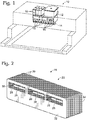
- Fig. 1 shows an inkjet printer 10 that includes multiple ink supplies 12, a laminate ink manifold 14, and inkjet printheads 16.
- the laminate manifold 14 provides fluidic pathways for the ink to flow from an ink supply 12 to the corresponding inkjet printhead 16, and therefore simultaneously interfaces with a fluid interface (the ink supply, typically having a millimeter scale) and a microscale fluid interface (the printhead die).
- Laminate manifold 18 includes a plurality of parallel plates 20 arranged into a plate stack 22.
- the individual plates 20 in the plate stack 22 are secured by a securing agent 24 (shown in Fig. 4 ).
- At least some of the plates 20 in the plate stack 22 incorporate one or more apertures 26.
- the plates 20 are generally arranged in the plate stack 22 in parallel. That is, the plane of each plate is substantially parallel to the plane of each other plate. It is expected that each plate will exhibit minor deviations from being perfectly planar, and that the plane defined by each plate may deviate from being perfectly parallel to every other plate in the plate stack 22. As described herein, the plates are arranged substantially in parallel, for example within +/- 10 degrees of being parallel.
- An aperture refers to any hole, void, slit, slot, or perforation of the plate material.
- the aperture may have an open edge or boundary, particularly where the aperture is adjacent an edge of the plate, or extends to an edge of the plate. Where the aperture is entirely and continuously defined by plate material, it is a closed or internal aperture.
- the various apertures may be of any size or shape necessary to fulfill the operating requirements of the resulting laminate manifold.
- the individual apertures 26 in the stacked plates 20 are oriented and placed such that when the plates are placed in an ordered parallel stack 22, the apertures define at least one fluidic pathway 28 within the plate stack 22.
- the fluidic pathway 28 will have an origin 30 at a face 32 or side 34 of the laminate manifold 18, and a terminus 36 on a side 34' of the laminate manifold 18.
- the origin 30 of a fluidic pathway includes an interface at a millimeter scale while the terminus includes a microscale interface.
- each fluidic pathway (28) emerges from the laminate plate stack between parallel plates. That is, the terminus (36) of each fluidic pathway is at least partially defined by at least two parallel plates.
- the fluidic pathway may exit the laminate manifold between two adjacent plates, if there is sufficient space between the adjacent plates. For example, where the interplate space is left empty, and not filled with an adhesive. More typically, the parallel plates that help define the fluidic pathway terminus are separated by a space corresponding to the width of one or more intervening plates, and are formed by apertures present in those intervening plates.
- the fluidic pathway emerges from the laminate plate stack in a direction substantially parallel to the plane of the parallel plates.
- the terminus 36 is disposed on a lower side of the manifold 34' and the fluidic pathway emerges from the laminate plate stack in a direction substantially parallel to the plane of the parallel plates.
- Fluid may be urged along a fluidic pathway with aid of capillary forces, pressure differentials, or any other suitable motive force.
- gravity may aid the flow of fluid within the fluidic pathway.
- disruption of fluid flow by bubbles within the pathway may be minimized or avoided, as the substantially vertical orientation of the fluidic pathway in combination with its geometric profile in cross section may permit bubbles within the fluidic pathway to escape the manifold.
- the securing agent 24 may be any agent that serves to securely bind the individual plates 20 into a unitary laminate manifold 18.
- the securing agent may be completely mechanical, such as a clamp, or jig assembly.
- the securing agent may be a discrete substance used to secure the plates of the laminate stack to each other.
- the securing agent 24 is an adhesive that fills the interplate spaces 38 within the plate stack 22.
- the adhesive may be applied as a film, via a spray application, via dipping, or any other suitable application method.
- the stacked plates are dipped into adhesive, and the adhesive wicks via capillary action into the interplate spaces of the plate stack.
- the adhesive 24 may therefore be selected to be capable of wicking into the interplate spaces completely, while not obstructing the apertures 26 present in the plates.
- the securing agent 24 will therefore, in combination with the plates 20 themselves, define the fluidic pathways 28 within the laminate manifold 18.
- the plates of the laminate manifold may additionally feature one or more stand off features 40, as shown in Fig. 4 .
- the stand off features are optionally formed from the material of the plates 20 themselves, and serve to create a defined and reproducible spacing 42 between the individual plates 20.
- discrete stand off features may be added or affixed to the individual plates before they are incorporated into a laminate manifold.
- the stand off features 40 help create a uniform spacing 42 between the plates 20.
- the laminate plates themselves may be uniform in thickness, or may vary in thickness.
- the plates disposed between adjacent terminuses of fluidic pathways may be selected to be somewhat thinner, with respect to other plates in the laminate plate stack, in order to accommodate particularly closely spaced features on a printhead die, for example.
- the plate thickness and stand off features may be selected so that the resulting laminate manifold exhibits a plate pitch geometry of between about 1060 microns to about 400 microns, or less.
- the terminus openings of a laminate manifold may be about 12 microns to about 1 millimeter in width.
- Laminate manifolds as disclosed herein, are generally configured to supply fluid to a mating fluidic assembly.
- the mating fluidic assembly may incorporate extremely small fluidic features, and so the laminate manifold must be prepared to correspond to, match with, and cross-feed to its mating fluidic assemblies.
- the terminus opening of the fluidic pathways may be mated to a silicon die that is a component of an inkjet printer, such as an inkjet printhead.
- the laminate structure of the disclosed manifolds can provide terminus openings smaller than those obtainable by molding or die casting.
- a representative method of manufacture of the laminate manifolds described herein is set out in Fig. 5 , at 44, and includes preparing a plurality of plates having a desired geometry at 46, forming apertures in at least some of the plates at 48, arranging the plates into a laminate plate stack at 50, and securing the plates in the laminate plate stack by applying a securing agent to the prepared plates at 52, so that the apertures in the plates define at least one fluidic pathway within the laminate plate stack that emerges from the laminate plate stack between parallel plates.
- This method of manufacture may further include machining one or more sides of the laminate plate stack 54.
- the step of forming apertures in the prepared plates may include forming standoffs in the plates, either simultaneously or sequentially.
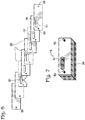
- Fig. 6 depicts a simple array of prepared plates 20, including apertures 26, while Fig. 7 depicts the completed laminate manifold formed by the plates of Fig. 6 , showing the single fluidic pathway origin 30 and terminus 36.
- Locating holes 58 may also be formed via progressive die stamping and are configured in size and location to mate with a corresponding alignment feature, such as pin 60, to properly orient the plates and help secure them in a stack.
- Laminate plates may be prepared from materials with high temperature capabilities (such as metals, ceramics, glass, and the like), or lower temperature materials such as polymers. By selecting the thermal properties of the laminate material carefully, a manifold may be prepared that closely matches the coefficient of thermal expansion (CTE) and/or the stiffness of a silicon printhead die. Each class of material has certain advantages, but they may require different securing agents or methods when preparing the laminate manifold.
- the laminate plates are prepared from stainless steel, glass, ceramic, or polymeric materials.
- a plate prepared from a material that is chemically resistant may be used so as to confer chemical resistance onto the resulting manifold.
- such plates may be prepared from chemically resistant stainless steel, such as SS 316L.
- the material may be selected to exhibit a selected coefficient of thermal expansion (CTE), in order to match the CTE of a mating fluidic assembly.
- the plates may be prepared from an alloy such as KOVAR (a nickel-cobalt ferrous alloy), or INVAR (a nickel steel alloy), silicon carbides, or silicon nitrides.
- the apertures may be formed in the plates by any method that is compatible with the material of the plates and that is capable of forming apertures of the desired dimensions, such as photolithography, milling, punching, and/or molding.
- the desired apertures are formed in selected metal plates using mechanical stamping.
- progressive die stamping may offer a low cost manufacturing method that is economical in direct material costs and in combination with the stacking laminate design permits the formation of apertures, and optionally stand off features, having the necessary fine structure for preparation of the described fluidic manifolds.
- the resulting manifolds may be used to achieve printhead ink manifolds of any desired size and scale.
- a rigid manifold structure may permit the manufacture of print bars that are better adapted to withstand the loads and stresses typically involved in capping and servicing of the print bar.
- the plates are secured in the laminate plate stack by applying a securing agent to the prepared plates.
- a securing agent capable of bonding the individual plates into a unitary laminate manifold is a suitable securing agent.
- the securing agent may include chemical means, such as adhesives or other substances, or physical treatments, such as the application of heat and/or pressure.
- the plates are optionally secured by way of brazing, soldering, or diffusion bonding. Alternatively, or in addition, the plates may be secured by a physical means, such as brackets, mountings, or fasteners.
- the plates may be arranged into a stack before securing, or the securing agent may be applied to the plates prior to arranging them into the desired stack, or even prior to forming apertures in the plates.
- the securing agent may act essentially instantaneously, or be activated by the application of thermal energy or alternative activating agent.
- a securing agent is applied to a first face of the laminate plates, while an activating agent for the selected securing agent is applied to the opposite face, such that upon contact with an adjacent plate, the securing agent becomes activated, securing the laminate plates.
- the selection of securing agent may vary depending on the chosen composition of the laminate plates.
- any suitable securing agent may be used to secure the plates into a single laminate manifold, it may be particularly advantageous to form the laminate manifold by partial or complete immersion of the plate stack into an adhesive bath, where the adhesive is selected to be capable of wicking into the interplate spaces of the plate. Once the adhesive has fully penetrated the plate stack assembly, the assembly may be removed from the adhesive, any excess adhesive may be removed and the adhesive may be cured.
- the present laminate plate stacks may also be further machined, if necessary.
- one or more sides of a rigid laminate plate stack may be machined to a degree of flatness that is not possible using conventional molded plastic manifold structures.
- the use of polymeric plates may result in laminate plate stacks having sides that may be machined or otherwise formed with an advantageous degree of flatness, but a greater precision may be obtained using more rigid plate materials, such as metal or ceramic materials.
- a greater degree of flatness may further enable a reduction in silicon die size. As the areas of contact between the silicon die and the side of the laminate manifold become more perfectly flat, the tendency of occlusions resulting from securing the die with a bonding agent to the manifold structure to block one or more fluidic pathways is reduced.
- a variety of fabrication methods may be used to prepare the disclosed laminate manifold structures, employing a variety of materials and manufacturing techniques.
- the following example is intended to serve as a representative method.
- a series of plates having the desired feed geometry and size and number of apertures are formed using a progressive die set.
- Stainless steel plates useful for manufacture of the laminate manifold may be as thin as about 12 microns.
- any desired stand off features are also formed in the plate using, for example, partial die cuts or other suitable method.
- Any locational features to aid in assembly may also formed via progressive die stamping. The locational features may be configured to mate with a corresponding alignment feature that is optionally incorporated into an assembly jig.
- the plates are cleaned to ensure that no fabrication oils or other contaminates exist on the plate surfaces.
- the plates may be further treated, if desired, to promote wetting and adhesion, such as by oxygen plasma treatment, nitric acid treatment, or similar activating treatment.
- the fabricated plates are then stacked in the appropriate sequence in a jig.
- Alignment of the plates may be accomplished by simply accurately stacking the plates (relying on overall dimensions of the plates) or by one or more alignment features that mate with locational features formed in the plates. For example, the formation of two apertures in each plate configured to align with two alignment pins in the jig could be used to accurately align the plate stack, but a variety of additional alignment aids may be similarly envisioned.
- the entire plate stack is temporarily clamped or otherwise secured. While held in the proper alignment, the plate stack may be permanently bonded together into a single laminate manifold.
- a variety of methods may be used to secure the plate stack, from diffusion bonding and microwelding to the application of a suitable adhesive material either before or after the plates are arranged into the desired stack.
- the laminate manifold is secured by partial or complete immersion of the plate stack into an adhesive bath, such that the adhesive wicks into the interplate spaces of the plate. Once the adhesive has fully penetrated the plate stack assembly, the assembly is removed from the adhesive, any excess adhesive is removed and the adhesive is cured.
- the type of curing action will depend on the type of adhesive used.
- the adhesive may be cured by placing the plate stack assembly into an oven and heating it to the necessary temperature for curing to take place. Any other type of curing may be used, provided it is compatible with the plate stack assembly.
- the adhesive may be formulated to be a dual cure formulation, with an initial cure via UV exposure to stabilize the adhesive, followed by a thermal cure to fix the adhesive permanently.
- the laminate manifold may be machined further, if needed and/or desired.
- the laminate manifold may be retained in the securing mechanism during machining, in order to increase the security of the laminate manifold, and enhance the ease of handling.
- the laminate manifold may remain in the jig while one or more sides of the laminate manifold is machined flat.
- the laminate manifold may be machined in any way that is advantageous for the application it is intended for.
- a side of the laminate manifold may be machined to a slight angle, or with a concavity or convexity.
- the present disclosure should not be intended to limit such further modification of the laminate manifold.
- the laminate manifold may be removed from the securing mechanism, and cleaned.
- the manifold may be cleaned ultrasonically, by immersion in a compatible solvent, or by any other suitable method.
- the completed laminate manifold may then be incorporated into a desired mechanism, such as an inkjet printer or other microfluidic apparatus.
- FIG. 8 An exemplary printhead assembly 62 incorporating a laminate manifold 64 is depicted in exploded view in Fig. 8 .
- Printhead assembly 62 is oriented in Fig. 8 so that the silicon dies of the printhead assembly are facing upwards, in order to more clearly show selected details of the assembly. In operation, however, the printhead assembly typically would be oriented with the silicon dies directed towards the media, which is generally downwards.
- Laminate plates 66 are aligned in the desired order and orientation, and incorporate the appropriate apertures 68 to form the desired fluidic pathways, as well as apertures configured to be locational features 70.
- the laminate manifold 64 is bracketed by and coupled to a laminate manifold mounting 72 that incorporates the interface between the individual ink supplies and the origins of the fluidic pathways defined by the laminate manifold for each type of ink.
- Silicon dies 74 are affixed to the laminate manifold 64. Silicon dies 74 are bound to the laminate manifold in such a manner as to form the necessary interface between the terminuses of the fluidic pathways defined by the laminate manifold and the fluidic features of the silicon die itself. The silicon dies are shown coupled to flexible circuits 76, permitting a printhead controller to have an electronic connection to the silicon dies.
- Fig. 9 shows the printhead assembly 62 of Fig. 8 in a corresponding non-exploded view.
- the printhead assembly is again oriented with the silicon dies facing upwards for the sake of clarity.
- the laminate manifold is secured within the laminate manifold mount 72 at least partially by fasteners 78.
- Fig. 10 depicts a portion of the printhead assembly 62 in its operational orientation, with silicon dies 74 directed downward.
- Fig. 11 is a cross section of the printhead assembly of Fig. 9 , in particular showing the ink supply conduits 80 within the laminate manifold mount and their interface with the fluidic pathways 82 of the laminate manifold 66.
- the laminate fluidic manifolds disclosed herein possess substantial advantages over previous types of manifold structures. Where the laminate manifold plates are prepared using progressive die stamping, the overall cost becomes competitive with the use of plastic manifolds, while enabling much finer features, and tighter slot pitch feeds for the purposes of printing. Where the laminate manifolds may be prepared from metals or ceramics, they may demonstrate structural stability and stiffness, particularly when prepared from stainless steel. In comparison with an injection molded manifold prepared from LCP (liquid crystal polymer) or other plastic, a stainless steel laminate manifold with the same geometry exhibits substantially less deflection than that observed for a plastic manifold when placed under the same load. The additional stiffness for a comparable cross section attained with the disclosed laminate manifolds permit the manufacture of longer print bar spans for a given deflection, and therefore enable larger print bar lengths for large scale printers.
- LCP liquid crystal polymer
- the size of the fluidic pathways defined by the laminate manifold, particularly the terminus of each fluidic pathway, is at least partially determined by the thickness of the plates used to assemble the manifold, and the securing agent used to bond the plates into a single laminate assembly.
- a slot pitch geometry in the range of less than 1 millimeter is achievable. This fine spacing permits a similarly small scale when fabricating a corresponding silicon die for use in manufacturing a printhead for inkjet printing.
- the potential reduction in the use of silicon creates a significant cost savings for the fabrication of the print system overall.
- millimeter scale to microscale fluidic systems may be readily coupled in a cost efficient manner, and without the need for costly photolithographic processes or expensive materials.
Landscapes
- Engineering & Computer Science (AREA)
- Manufacturing & Machinery (AREA)
- Particle Formation And Scattering Control In Inkjet Printers (AREA)
- Ink Jet (AREA)
Claims (15)
- Schichtverteiler (18) zum Koppeln an einen Druckkopf, der einen Siliziumchip umfasst, wobei der Schichtverteiler Folgendes umfasst:mehrere parallele Platten (20), die in einem Schichtplattenstapel (22) angeordnet sind; undein Befestigungsmittel (24) zum Befestigen der Platten in dem Schichtplattenstapel (22); wobei wenigstens einige der Platten eine oder mehrere Öffnungen (26) beinhalten, die in ihren entsprechenden Platten derart ausgerichtet sind, dass, wenn die Platten als ein Schichtplattenstapel angeordnet sind, die Öffnungen wenigstens eine fluidische Leitung (28) definieren;wobei die fluidische Leitung (28) von dem Schichtplattenstapel zwischen parallelen Platten hervorkommt.
- Schichtverteiler nach Anspruch 1, wobei die fluidische Leitung von dem Schichtplattenstapel in einer Richtung hervorkommt, die parallel zu der Ebene der parallelen Platten liegt.
- Schichtverteiler nach Anspruch 1, wobei der Schichtplattenstapel (22) mehrere eigenständige fluidische Leitungen (28) definiert, wobei jede fluidische Leitung einen Anfangspunkt (30) an einer Fläche des Schichtplattenstapels und einen Endpunkt (36) aufweist, der wenigstens teilweise durch wenigstens zwei parallele Platten definiert ist.
- Schichtverteiler nach Anspruch 1, wobei das Befestigungsmittel (24) ein Klebstoff ist.
- Schichtverteiler nach Anspruch 1, wobei die parallelen Platten (20) ferner eine oder mehrere Abstandseigenschaften (40) beinhalten, konfiguriert, um einen vorgegebenen Zwischenplattenabstand (42) beizubehalten.
- Schichtverteiler nach Anspruch 1, wobei jeder Endpunkt (36) einer fluidischen Leitung eine Breite von etwa 12 Mikrometern bis etwa 1 Millimeter aufweist.
- Schichtverteiler nach Anspruch 1, wobei die parallelen Platten (20) rostfreier Stahl, Glas, Keramik oder polymere Stoffe sind.
- Schichtverteiler nach Anspruch 1, wobei der Anfangspunkt (30) jeder fluidischen Leitung (28) an eine Fluidquelle (12, 80) gekoppelt ist.
- Schichtverteiler nach Anspruch 1, wobei der Anfangspunkt (30) jeder fluidischen Leitung (28) direkt oder indirekt an eine Zufuhr von Fluidtinte (12, 80) gekoppelt ist und der Endpunkt (36) jeder fluidischen Leitung (28) direkt oder indirekt an einen Druckkopfchip (74) gekoppelt ist.
- Verfahren (44) zum Herstellen eines Schichtverteilers zum Koppeln an einen Druckkopf, der einen Siliziumchip umfasst, wobei das Verfahren Folgendes umfasst:a) Herstellen mehrere Platten mit einer erwünschten Geometrie (46);b) Ausbilden von Öffnungen in wenigstens einigen der Platten (48);c) Anordnen der Platten in einen Schichtplattenstapel (50); undd) Befestigen der Platten in dem Schichtplattenstapel durch Auftragen eines Befestigungsmittels auf die Platten (52);wobei die Öffnungen in den Platten wenigstens eine fluidische Leitung in dem Schichtplattenstapel definieren, die von dem Schichtplattenstapel zwischen parallelen Platten hervorkommt.
- Verfahren nach Anspruch 10, wobei das Befestigen der Platten Folgendes enthält: Aufsaugen eines Klebstoffes zwischen nicht-durchlöcherten Bereichen der Platten und Aushärten des Klebstoffes in dem Schichtplattenstapel.
- Verfahren nach Anspruch 10, wobei das Anordnen (50) der hergestellten Platten in einen Schichtplattenstapel (22) dazu führt, dass die Öffnungen (26) mehrere fluidische Leitungen (28) definieren, wobei jede fluidische Leitung einen Anfangspunkt (30) an einer Fläche des Schichtplattenstapels (22) und einen Endpunkt (36) aufweist, der wenigstens teilweise durch wenigstens zwei parallele Platten definiert ist.
- Verfahren nach Anspruch 10, wobei das Anordnen (50) der hergestellten Platten in einen Schichtplattenstapel (22) dazu führt, dass die Öffnungen (26) mehrere fluidische Leitungen (28) definieren, wobei jede fluidische Leitung zwischen parallelen Platten eintritt beziehungsweise hervorkommt.
- Verfahren nach Anspruch 10, wobei das Herstellen (46) der mehreren Platten das Herstellen mehrerer rostfreier Stahlplatten beinhaltet; und wobei das Ausbilden (48) der Öffnungen das Ausbilden von Öffnungen in wenigstens einigen der hergestellten Platten unter Verwendung von mechanischem Prägen beinhaltet.
- Tintenstrahldrucker (10), Folgendes umfassend:mehrere Tintenreservoirs (12);wenigstens einen Druckkopf, der einen Siliziumchip (74) umfasst; undwenigstens einen Tintenschichtverteiler (14, 66), der Folgendes beinhaltet: mehrere parallele Platten (20), die in einem Schichtplattenstapel (22, 64) angeordnet sind, und ein Befestigungsmittel (24), das die Platten in dem Schichtplattenstapel befestigt; wobei wenigstens einige der Platten eine oder mehrere Öffnungen (26, 68) beinhalten, die in ihren entsprechenden Platten derart ausgerichtet sind, dass, wenn die Platten als ein Schichtplattenstapel angeordnet sind, die Öffnungen wenigstens eine fluidische Leitung (28, 82) definieren; und wobei jede fluidische Leitung einen Anfangspunkt (30), der mit einem Tintenreservoir (12) fluidisch gekoppelt ist, aufweist und jede fluidische Leitung einen Endpunkt (36) aufweist, der wenigstens teilweise durch wenigstens zwei parallele Platten definiert ist, und fluidisch an den Siliziumchip (74) gekoppelt ist;derart, dass Tinte von jedem Tintenreservoir (12) durch wenigstens einen Schichtverteiler (14, 66) an wenigstens einen Siliziumchip (74) geliert wird.
Applications Claiming Priority (1)
| Application Number | Priority Date | Filing Date | Title |
|---|---|---|---|
| PCT/US2009/060371 WO2011046539A1 (en) | 2009-10-12 | 2009-10-12 | Laminate manifolds for mesoscale fluidic systems |
Publications (3)
| Publication Number | Publication Date |
|---|---|
| EP2488366A1 EP2488366A1 (de) | 2012-08-22 |
| EP2488366A4 EP2488366A4 (de) | 2014-03-26 |
| EP2488366B1 true EP2488366B1 (de) | 2018-09-05 |
Family
ID=43876379
Family Applications (1)
| Application Number | Title | Priority Date | Filing Date |
|---|---|---|---|
| EP09850457.4A Not-in-force EP2488366B1 (de) | 2009-10-12 | 2009-10-12 | Schichtverteiler für mesoskalige fluidsysteme |
Country Status (5)
| Country | Link |
|---|---|
| US (3) | US9555631B2 (de) |
| EP (1) | EP2488366B1 (de) |
| JP (1) | JP5659235B2 (de) |
| CN (1) | CN102548766B (de) |
| WO (1) | WO2011046539A1 (de) |
Families Citing this family (8)
| Publication number | Priority date | Publication date | Assignee | Title |
|---|---|---|---|---|
| JP6376328B2 (ja) * | 2014-03-17 | 2018-08-22 | セイコーエプソン株式会社 | 液体噴射ヘッド及び液体噴射装置 |
| CN106660369B (zh) * | 2014-07-17 | 2019-01-15 | 惠普发展公司,有限责任合伙企业 | 打印杆结构 |
| WO2016186603A1 (en) * | 2015-05-15 | 2016-11-24 | Hewlett-Packard Development Company, L.P. | Fluid ejection device |
| EP3573812B1 (de) * | 2017-05-01 | 2023-01-04 | Hewlett-Packard Development Company, L.P. | Formplatten |
| NL2020616B1 (en) | 2018-02-03 | 2019-08-14 | Illumina Inc | Cartridge with laminated manifold |
| WO2019168875A1 (en) | 2018-02-28 | 2019-09-06 | Illinois Tool Works Inc. | Nozzle for discharging one or more fluids |
| US12065728B2 (en) | 2020-05-11 | 2024-08-20 | Universal Display Corporation | Apparatus and method to deliver organic material via organic vapor jet printing (OVJP) |
| US11751466B2 (en) * | 2020-05-11 | 2023-09-05 | Universal Display Corporation | Apparatus and method to deliver organic material via organic vapor jet printing (OVJP) |
Family Cites Families (27)
| Publication number | Priority date | Publication date | Assignee | Title |
|---|---|---|---|---|
| US4883219A (en) | 1988-09-01 | 1989-11-28 | Anderson Jeffrey J | Manufacture of ink jet print heads by diffusion bonding and brazing |
| US5489930A (en) | 1993-04-30 | 1996-02-06 | Tektronix, Inc. | Ink jet head with internal filter |
| US5907338A (en) | 1995-01-13 | 1999-05-25 | Burr; Ronald F. | High-performance ink jet print head |
| JPH10166581A (ja) | 1996-12-06 | 1998-06-23 | Seiko Epson Corp | インクジェット式記録ヘッド、及びその製造方法 |
| FR2766742B1 (fr) | 1997-07-31 | 1999-09-24 | Stein Heurtey | Dispositif de transfert entre une premiere enceinte de prechauffage et une seconde enceinte de rechauffage |
| US6123410A (en) | 1997-10-28 | 2000-09-26 | Hewlett-Packard Company | Scalable wide-array inkjet printhead and method for fabricating same |
| US6652078B2 (en) | 2000-05-23 | 2003-11-25 | Silverbrook Research Pty Ltd | Ink supply arrangement for a printer |
| US6488422B1 (en) | 2000-05-23 | 2002-12-03 | Silverbrook Research Pty Ltd | Paper thickness sensor in a printer |
| US7213989B2 (en) | 2000-05-23 | 2007-05-08 | Silverbrook Research Pty Ltd | Ink distribution structure for a printhead |
| US6786658B2 (en) * | 2000-05-23 | 2004-09-07 | Silverbrook Research Pty. Ltd. | Printer for accommodating varying page thicknesses |
| US6463656B1 (en) * | 2000-06-29 | 2002-10-15 | Eastman Kodak Company | Laminate and gasket manfold for ink jet delivery systems and similar devices |
| JP2002178509A (ja) * | 2000-12-12 | 2002-06-26 | Olympus Optical Co Ltd | 液滴噴射装置 |
| US7311380B2 (en) | 2002-09-26 | 2007-12-25 | Brother Kogyo Kabushiki Kaisha | Inkjet head |
| JP2005022088A (ja) | 2003-06-30 | 2005-01-27 | Brother Ind Ltd | 薄板部材の積層接着構造及びインクジェットヘッド |
| JP2005081545A (ja) * | 2003-09-04 | 2005-03-31 | Brother Ind Ltd | インクジェットプリンタヘッド |
| JP4003743B2 (ja) * | 2003-12-11 | 2007-11-07 | ブラザー工業株式会社 | インクジェットプリンタ |
| US7159972B2 (en) | 2004-01-21 | 2007-01-09 | Silverbrook Research Pty Ltd | Printhead module having selectable number of fluid channels |
| KR20060039111A (ko) | 2004-11-02 | 2006-05-08 | 삼성전자주식회사 | 캔틸레버 액츄에이터를 구비한 잉크젯 프린트헤드 |
| US7347533B2 (en) | 2004-12-20 | 2008-03-25 | Palo Alto Research Center Incorporated | Low cost piezo printhead based on microfluidics in printed circuit board and screen-printed piezoelectrics |
| JP2007062082A (ja) * | 2005-08-30 | 2007-03-15 | Dainippon Printing Co Ltd | インクジェットヘッド及びその製造方法 |
| CN101037040A (zh) * | 2006-03-15 | 2007-09-19 | 明基电通股份有限公司 | 集成尺寸侦测器之微喷射装置 |
| JP5004497B2 (ja) * | 2006-04-26 | 2012-08-22 | 株式会社リコー | 液体吐出ヘッド、液体吐出装置、画像形成装置 |
| JP2008183803A (ja) | 2007-01-30 | 2008-08-14 | Brother Ind Ltd | 液滴噴射装置 |
| JP2008183804A (ja) | 2007-01-30 | 2008-08-14 | Brother Ind Ltd | 液滴噴射装置 |
| JP4947308B2 (ja) * | 2007-01-30 | 2012-06-06 | ブラザー工業株式会社 | 液滴吐出ヘッド |
| JP4924220B2 (ja) | 2007-06-08 | 2012-04-25 | ブラザー工業株式会社 | 液体吐出装置 |
| JP6376328B2 (ja) | 2014-03-17 | 2018-08-22 | セイコーエプソン株式会社 | 液体噴射ヘッド及び液体噴射装置 |
-
2009
- 2009-10-12 EP EP09850457.4A patent/EP2488366B1/de not_active Not-in-force
- 2009-10-12 US US13/259,442 patent/US9555631B2/en not_active Expired - Fee Related
- 2009-10-12 JP JP2012534148A patent/JP5659235B2/ja not_active Expired - Fee Related
- 2009-10-12 WO PCT/US2009/060371 patent/WO2011046539A1/en not_active Ceased
- 2009-10-12 CN CN200980161911.XA patent/CN102548766B/zh not_active Expired - Fee Related
-
2016
- 2016-12-15 US US15/380,262 patent/US9868284B2/en not_active Expired - Fee Related
-
2017
- 2017-12-08 US US15/836,768 patent/US10124589B2/en active Active
Non-Patent Citations (1)
| Title |
|---|
| None * |
Also Published As
| Publication number | Publication date |
|---|---|
| US20170096005A1 (en) | 2017-04-06 |
| JP5659235B2 (ja) | 2015-01-28 |
| EP2488366A1 (de) | 2012-08-22 |
| US10124589B2 (en) | 2018-11-13 |
| CN102548766B (zh) | 2015-04-29 |
| WO2011046539A1 (en) | 2011-04-21 |
| EP2488366A4 (de) | 2014-03-26 |
| CN102548766A (zh) | 2012-07-04 |
| US20120019600A1 (en) | 2012-01-26 |
| JP2013507282A (ja) | 2013-03-04 |
| US9555631B2 (en) | 2017-01-31 |
| US9868284B2 (en) | 2018-01-16 |
| US20180099502A1 (en) | 2018-04-12 |
Similar Documents
| Publication | Publication Date | Title |
|---|---|---|
| US10124589B2 (en) | Laminate manifolds for mesoscale fluidic systems | |
| EP0379781B1 (de) | Flüssigkeitsstrahlaufzeichnungsvorrichtung | |
| JP5380430B2 (ja) | マイクロ流体デバイス及びマイクロ流体デバイスを内蔵する流体射出デバイス | |
| EP1212164B1 (de) | Flüssigkeitsmikroventil und verfahren zum ultrasonen verbinden | |
| US7695114B2 (en) | Inkjet head and method of producing the same | |
| EP3196023B1 (de) | Tintenstrahlkopf, tintenstrahlkopfmodul und tintenstrahldrucker | |
| CN101890401A (zh) | 具有聚合物层的流体分配组件 | |
| US20050116995A1 (en) | Head module, liquid jetting head, liquid jetting apparatus, method of manufacturing head module, and method of manufacturing liquid jetting head | |
| CA2591951A1 (en) | Inkjet printhead production method | |
| US7946037B2 (en) | Microchemical device and method for fabricating the same | |
| US8047156B2 (en) | Dice with polymer ribs | |
| US7891798B2 (en) | Micro-fluidic device having an improved filter layer and method for assembling a micro-fluidic device | |
| JP2009090538A (ja) | プラスチック薄膜の製造方法 | |
| US8210661B2 (en) | Stacked slice printhead | |
| EP0867287B1 (de) | Tintenstrahldruckkopf | |
| US20030076386A1 (en) | Inkjet print head and method for making the same | |
| JP4033371B2 (ja) | インクジェットヘッド及びその製造方法、画像形成装置 | |
| JP2011110792A (ja) | 液体吐出ヘッドの製造方法 | |
| EP1829689B1 (de) | Tintenstrahldruckkopf und Herstellungsverfahren dafür | |
| JP7292998B2 (ja) | インクジェットヘッド及びインクジェットプリンタ | |
| CN101590742A (zh) | 热敏头单元的制造方法、热敏头单元和包括热敏头单元的打印装置 | |
| JPH06255109A (ja) | インクジェット記録ヘッド及びその製造方法 | |
| US7631959B2 (en) | Ink jet head structure and adhering method thereof | |
| US8684499B2 (en) | Method for forming an aperture and actuator layer for an inkjet printhead | |
| JP2009090616A (ja) | プラスチック薄膜の製造方法 |
Legal Events
| Date | Code | Title | Description |
|---|---|---|---|
| PUAI | Public reference made under article 153(3) epc to a published international application that has entered the european phase |
Free format text: ORIGINAL CODE: 0009012 |
|
| 17P | Request for examination filed |
Effective date: 20120113 |
|
| AK | Designated contracting states |
Kind code of ref document: A1 Designated state(s): AT BE BG CH CY CZ DE DK EE ES FI FR GB GR HR HU IE IS IT LI LT LU LV MC MK MT NL NO PL PT RO SE SI SK SM TR |
|
| DAX | Request for extension of the european patent (deleted) | ||
| A4 | Supplementary search report drawn up and despatched |
Effective date: 20140225 |
|
| RIC1 | Information provided on ipc code assigned before grant |
Ipc: B41J 2/175 20060101AFI20140219BHEP Ipc: B41J 2/14 20060101ALI20140219BHEP |
|
| REG | Reference to a national code |
Ref country code: DE Ref legal event code: R079 Ref document number: 602009054402 Country of ref document: DE Free format text: PREVIOUS MAIN CLASS: B41J0002175000 Ipc: B41J0002160000 |
|
| GRAP | Despatch of communication of intention to grant a patent |
Free format text: ORIGINAL CODE: EPIDOSNIGR1 |
|
| RIC1 | Information provided on ipc code assigned before grant |
Ipc: B41J 2/14 20060101ALI20180411BHEP Ipc: B41J 2/16 20060101AFI20180411BHEP Ipc: B41J 2/175 20060101ALI20180411BHEP |
|
| INTG | Intention to grant announced |
Effective date: 20180423 |
|
| GRAS | Grant fee paid |
Free format text: ORIGINAL CODE: EPIDOSNIGR3 |
|
| GRAA | (expected) grant |
Free format text: ORIGINAL CODE: 0009210 |
|
| AK | Designated contracting states |
Kind code of ref document: B1 Designated state(s): AT BE BG CH CY CZ DE DK EE ES FI FR GB GR HR HU IE IS IT LI LT LU LV MC MK MT NL NO PL PT RO SE SI SK SM TR |
|
| REG | Reference to a national code |
Ref country code: GB Ref legal event code: FG4D |
|
| REG | Reference to a national code |
Ref country code: CH Ref legal event code: EP |
|
| REG | Reference to a national code |
Ref country code: AT Ref legal event code: REF Ref document number: 1037336 Country of ref document: AT Kind code of ref document: T Effective date: 20180915 |
|
| REG | Reference to a national code |
Ref country code: IE Ref legal event code: FG4D |
|
| REG | Reference to a national code |
Ref country code: DE Ref legal event code: R096 Ref document number: 602009054402 Country of ref document: DE |
|
| REG | Reference to a national code |
Ref country code: FR Ref legal event code: PLFP Year of fee payment: 10 |
|
| REG | Reference to a national code |
Ref country code: NL Ref legal event code: MP Effective date: 20180905 |
|
| REG | Reference to a national code |
Ref country code: LT Ref legal event code: MG4D |
|
| PG25 | Lapsed in a contracting state [announced via postgrant information from national office to epo] |
Ref country code: SE Free format text: LAPSE BECAUSE OF FAILURE TO SUBMIT A TRANSLATION OF THE DESCRIPTION OR TO PAY THE FEE WITHIN THE PRESCRIBED TIME-LIMIT Effective date: 20180905 Ref country code: NO Free format text: LAPSE BECAUSE OF FAILURE TO SUBMIT A TRANSLATION OF THE DESCRIPTION OR TO PAY THE FEE WITHIN THE PRESCRIBED TIME-LIMIT Effective date: 20181205 Ref country code: FI Free format text: LAPSE BECAUSE OF FAILURE TO SUBMIT A TRANSLATION OF THE DESCRIPTION OR TO PAY THE FEE WITHIN THE PRESCRIBED TIME-LIMIT Effective date: 20180905 Ref country code: GR Free format text: LAPSE BECAUSE OF FAILURE TO SUBMIT A TRANSLATION OF THE DESCRIPTION OR TO PAY THE FEE WITHIN THE PRESCRIBED TIME-LIMIT Effective date: 20181206 Ref country code: BG Free format text: LAPSE BECAUSE OF FAILURE TO SUBMIT A TRANSLATION OF THE DESCRIPTION OR TO PAY THE FEE WITHIN THE PRESCRIBED TIME-LIMIT Effective date: 20181205 Ref country code: LT Free format text: LAPSE BECAUSE OF FAILURE TO SUBMIT A TRANSLATION OF THE DESCRIPTION OR TO PAY THE FEE WITHIN THE PRESCRIBED TIME-LIMIT Effective date: 20180905 |
|
| REG | Reference to a national code |
Ref country code: AT Ref legal event code: MK05 Ref document number: 1037336 Country of ref document: AT Kind code of ref document: T Effective date: 20180905 |
|
| PG25 | Lapsed in a contracting state [announced via postgrant information from national office to epo] |
Ref country code: LV Free format text: LAPSE BECAUSE OF FAILURE TO SUBMIT A TRANSLATION OF THE DESCRIPTION OR TO PAY THE FEE WITHIN THE PRESCRIBED TIME-LIMIT Effective date: 20180905 Ref country code: HR Free format text: LAPSE BECAUSE OF FAILURE TO SUBMIT A TRANSLATION OF THE DESCRIPTION OR TO PAY THE FEE WITHIN THE PRESCRIBED TIME-LIMIT Effective date: 20180905 |
|
| PG25 | Lapsed in a contracting state [announced via postgrant information from national office to epo] |
Ref country code: IT Free format text: LAPSE BECAUSE OF FAILURE TO SUBMIT A TRANSLATION OF THE DESCRIPTION OR TO PAY THE FEE WITHIN THE PRESCRIBED TIME-LIMIT Effective date: 20180905 Ref country code: RO Free format text: LAPSE BECAUSE OF FAILURE TO SUBMIT A TRANSLATION OF THE DESCRIPTION OR TO PAY THE FEE WITHIN THE PRESCRIBED TIME-LIMIT Effective date: 20180905 Ref country code: PL Free format text: LAPSE BECAUSE OF FAILURE TO SUBMIT A TRANSLATION OF THE DESCRIPTION OR TO PAY THE FEE WITHIN THE PRESCRIBED TIME-LIMIT Effective date: 20180905 Ref country code: NL Free format text: LAPSE BECAUSE OF FAILURE TO SUBMIT A TRANSLATION OF THE DESCRIPTION OR TO PAY THE FEE WITHIN THE PRESCRIBED TIME-LIMIT Effective date: 20180905 Ref country code: CZ Free format text: LAPSE BECAUSE OF FAILURE TO SUBMIT A TRANSLATION OF THE DESCRIPTION OR TO PAY THE FEE WITHIN THE PRESCRIBED TIME-LIMIT Effective date: 20180905 Ref country code: ES Free format text: LAPSE BECAUSE OF FAILURE TO SUBMIT A TRANSLATION OF THE DESCRIPTION OR TO PAY THE FEE WITHIN THE PRESCRIBED TIME-LIMIT Effective date: 20180905 Ref country code: IS Free format text: LAPSE BECAUSE OF FAILURE TO SUBMIT A TRANSLATION OF THE DESCRIPTION OR TO PAY THE FEE WITHIN THE PRESCRIBED TIME-LIMIT Effective date: 20190105 Ref country code: AT Free format text: LAPSE BECAUSE OF FAILURE TO SUBMIT A TRANSLATION OF THE DESCRIPTION OR TO PAY THE FEE WITHIN THE PRESCRIBED TIME-LIMIT Effective date: 20180905 Ref country code: EE Free format text: LAPSE BECAUSE OF FAILURE TO SUBMIT A TRANSLATION OF THE DESCRIPTION OR TO PAY THE FEE WITHIN THE PRESCRIBED TIME-LIMIT Effective date: 20180905 |
|
| RAP2 | Party data changed (patent owner data changed or rights of a patent transferred) |
Owner name: HEWLETT-PACKARD DEVELOPMENT COMPANY, L.P. |
|
| PG25 | Lapsed in a contracting state [announced via postgrant information from national office to epo] |
Ref country code: SK Free format text: LAPSE BECAUSE OF FAILURE TO SUBMIT A TRANSLATION OF THE DESCRIPTION OR TO PAY THE FEE WITHIN THE PRESCRIBED TIME-LIMIT Effective date: 20180905 Ref country code: PT Free format text: LAPSE BECAUSE OF FAILURE TO SUBMIT A TRANSLATION OF THE DESCRIPTION OR TO PAY THE FEE WITHIN THE PRESCRIBED TIME-LIMIT Effective date: 20190105 Ref country code: SM Free format text: LAPSE BECAUSE OF FAILURE TO SUBMIT A TRANSLATION OF THE DESCRIPTION OR TO PAY THE FEE WITHIN THE PRESCRIBED TIME-LIMIT Effective date: 20180905 |
|
| REG | Reference to a national code |
Ref country code: CH Ref legal event code: PL |
|
| REG | Reference to a national code |
Ref country code: DE Ref legal event code: R097 Ref document number: 602009054402 Country of ref document: DE |
|
| REG | Reference to a national code |
Ref country code: BE Ref legal event code: MM Effective date: 20181031 |
|
| PG25 | Lapsed in a contracting state [announced via postgrant information from national office to epo] |
Ref country code: LU Free format text: LAPSE BECAUSE OF NON-PAYMENT OF DUE FEES Effective date: 20181012 |
|
| PLBE | No opposition filed within time limit |
Free format text: ORIGINAL CODE: 0009261 |
|
| STAA | Information on the status of an ep patent application or granted ep patent |
Free format text: STATUS: NO OPPOSITION FILED WITHIN TIME LIMIT |
|
| REG | Reference to a national code |
Ref country code: IE Ref legal event code: MM4A |
|
| PG25 | Lapsed in a contracting state [announced via postgrant information from national office to epo] |
Ref country code: DK Free format text: LAPSE BECAUSE OF FAILURE TO SUBMIT A TRANSLATION OF THE DESCRIPTION OR TO PAY THE FEE WITHIN THE PRESCRIBED TIME-LIMIT Effective date: 20180905 Ref country code: MC Free format text: LAPSE BECAUSE OF FAILURE TO SUBMIT A TRANSLATION OF THE DESCRIPTION OR TO PAY THE FEE WITHIN THE PRESCRIBED TIME-LIMIT Effective date: 20180905 |
|
| 26N | No opposition filed |
Effective date: 20190606 |
|
| PG25 | Lapsed in a contracting state [announced via postgrant information from national office to epo] |
Ref country code: LI Free format text: LAPSE BECAUSE OF NON-PAYMENT OF DUE FEES Effective date: 20181031 Ref country code: CH Free format text: LAPSE BECAUSE OF NON-PAYMENT OF DUE FEES Effective date: 20181031 Ref country code: SI Free format text: LAPSE BECAUSE OF FAILURE TO SUBMIT A TRANSLATION OF THE DESCRIPTION OR TO PAY THE FEE WITHIN THE PRESCRIBED TIME-LIMIT Effective date: 20180905 Ref country code: BE Free format text: LAPSE BECAUSE OF NON-PAYMENT OF DUE FEES Effective date: 20181031 |
|
| PG25 | Lapsed in a contracting state [announced via postgrant information from national office to epo] |
Ref country code: IE Free format text: LAPSE BECAUSE OF NON-PAYMENT OF DUE FEES Effective date: 20181012 |
|
| PG25 | Lapsed in a contracting state [announced via postgrant information from national office to epo] |
Ref country code: MT Free format text: LAPSE BECAUSE OF NON-PAYMENT OF DUE FEES Effective date: 20181012 |
|
| PG25 | Lapsed in a contracting state [announced via postgrant information from national office to epo] |
Ref country code: TR Free format text: LAPSE BECAUSE OF FAILURE TO SUBMIT A TRANSLATION OF THE DESCRIPTION OR TO PAY THE FEE WITHIN THE PRESCRIBED TIME-LIMIT Effective date: 20180905 |
|
| PG25 | Lapsed in a contracting state [announced via postgrant information from national office to epo] |
Ref country code: MK Free format text: LAPSE BECAUSE OF NON-PAYMENT OF DUE FEES Effective date: 20180905 Ref country code: CY Free format text: LAPSE BECAUSE OF FAILURE TO SUBMIT A TRANSLATION OF THE DESCRIPTION OR TO PAY THE FEE WITHIN THE PRESCRIBED TIME-LIMIT Effective date: 20180905 Ref country code: HU Free format text: LAPSE BECAUSE OF FAILURE TO SUBMIT A TRANSLATION OF THE DESCRIPTION OR TO PAY THE FEE WITHIN THE PRESCRIBED TIME-LIMIT; INVALID AB INITIO Effective date: 20091012 |
|
| PGFP | Annual fee paid to national office [announced via postgrant information from national office to epo] |
Ref country code: FR Payment date: 20210922 Year of fee payment: 13 |
|
| PGFP | Annual fee paid to national office [announced via postgrant information from national office to epo] |
Ref country code: GB Payment date: 20210922 Year of fee payment: 13 |
|
| PGFP | Annual fee paid to national office [announced via postgrant information from national office to epo] |
Ref country code: DE Payment date: 20220616 Year of fee payment: 14 |
|
| GBPC | Gb: european patent ceased through non-payment of renewal fee |
Effective date: 20221012 |
|
| PG25 | Lapsed in a contracting state [announced via postgrant information from national office to epo] |
Ref country code: FR Free format text: LAPSE BECAUSE OF NON-PAYMENT OF DUE FEES Effective date: 20221031 |
|
| PG25 | Lapsed in a contracting state [announced via postgrant information from national office to epo] |
Ref country code: GB Free format text: LAPSE BECAUSE OF NON-PAYMENT OF DUE FEES Effective date: 20221012 |
|
| REG | Reference to a national code |
Ref country code: DE Ref legal event code: R119 Ref document number: 602009054402 Country of ref document: DE |
|
| PG25 | Lapsed in a contracting state [announced via postgrant information from national office to epo] |
Ref country code: DE Free format text: LAPSE BECAUSE OF NON-PAYMENT OF DUE FEES Effective date: 20240501 |