EP2487740A1 - Système de pile à combustible et procédé pour arrêter un système de pile à combustible - Google Patents
Système de pile à combustible et procédé pour arrêter un système de pile à combustible Download PDFInfo
- Publication number
- EP2487740A1 EP2487740A1 EP09850209A EP09850209A EP2487740A1 EP 2487740 A1 EP2487740 A1 EP 2487740A1 EP 09850209 A EP09850209 A EP 09850209A EP 09850209 A EP09850209 A EP 09850209A EP 2487740 A1 EP2487740 A1 EP 2487740A1
- Authority
- EP
- European Patent Office
- Prior art keywords
- gas
- cathode
- fuel cell
- anode
- supply
- Prior art date
- Legal status (The legal status is an assumption and is not a legal conclusion. Google has not performed a legal analysis and makes no representation as to the accuracy of the status listed.)
- Granted
Links
Images


Classifications
-
- H—ELECTRICITY
- H01—ELECTRIC ELEMENTS
- H01M—PROCESSES OR MEANS, e.g. BATTERIES, FOR THE DIRECT CONVERSION OF CHEMICAL ENERGY INTO ELECTRICAL ENERGY
- H01M8/00—Fuel cells; Manufacture thereof
- H01M8/04—Auxiliary arrangements, e.g. for control of pressure or for circulation of fluids
-
- H—ELECTRICITY
- H01—ELECTRIC ELEMENTS
- H01M—PROCESSES OR MEANS, e.g. BATTERIES, FOR THE DIRECT CONVERSION OF CHEMICAL ENERGY INTO ELECTRICAL ENERGY
- H01M8/00—Fuel cells; Manufacture thereof
- H01M8/04—Auxiliary arrangements, e.g. for control of pressure or for circulation of fluids
- H01M8/04082—Arrangements for control of reactant parameters, e.g. pressure or concentration
- H01M8/04089—Arrangements for control of reactant parameters, e.g. pressure or concentration of gaseous reactants
- H01M8/04104—Regulation of differential pressures
-
- H—ELECTRICITY
- H01—ELECTRIC ELEMENTS
- H01M—PROCESSES OR MEANS, e.g. BATTERIES, FOR THE DIRECT CONVERSION OF CHEMICAL ENERGY INTO ELECTRICAL ENERGY
- H01M8/00—Fuel cells; Manufacture thereof
- H01M8/02—Details
- H01M8/0202—Collectors; Separators, e.g. bipolar separators; Interconnectors
- H01M8/0267—Collectors; Separators, e.g. bipolar separators; Interconnectors having heating or cooling means, e.g. heaters or coolant flow channels
-
- H—ELECTRICITY
- H01—ELECTRIC ELEMENTS
- H01M—PROCESSES OR MEANS, e.g. BATTERIES, FOR THE DIRECT CONVERSION OF CHEMICAL ENERGY INTO ELECTRICAL ENERGY
- H01M8/00—Fuel cells; Manufacture thereof
- H01M8/04—Auxiliary arrangements, e.g. for control of pressure or for circulation of fluids
- H01M8/04082—Arrangements for control of reactant parameters, e.g. pressure or concentration
- H01M8/04089—Arrangements for control of reactant parameters, e.g. pressure or concentration of gaseous reactants
- H01M8/04097—Arrangements for control of reactant parameters, e.g. pressure or concentration of gaseous reactants with recycling of the reactants
-
- H—ELECTRICITY
- H01—ELECTRIC ELEMENTS
- H01M—PROCESSES OR MEANS, e.g. BATTERIES, FOR THE DIRECT CONVERSION OF CHEMICAL ENERGY INTO ELECTRICAL ENERGY
- H01M8/00—Fuel cells; Manufacture thereof
- H01M8/04—Auxiliary arrangements, e.g. for control of pressure or for circulation of fluids
- H01M8/04223—Auxiliary arrangements, e.g. for control of pressure or for circulation of fluids during start-up or shut-down; Depolarisation or activation, e.g. purging; Means for short-circuiting defective fuel cells
- H01M8/04225—Auxiliary arrangements, e.g. for control of pressure or for circulation of fluids during start-up or shut-down; Depolarisation or activation, e.g. purging; Means for short-circuiting defective fuel cells during start-up
-
- H—ELECTRICITY
- H01—ELECTRIC ELEMENTS
- H01M—PROCESSES OR MEANS, e.g. BATTERIES, FOR THE DIRECT CONVERSION OF CHEMICAL ENERGY INTO ELECTRICAL ENERGY
- H01M8/00—Fuel cells; Manufacture thereof
- H01M8/04—Auxiliary arrangements, e.g. for control of pressure or for circulation of fluids
- H01M8/04223—Auxiliary arrangements, e.g. for control of pressure or for circulation of fluids during start-up or shut-down; Depolarisation or activation, e.g. purging; Means for short-circuiting defective fuel cells
- H01M8/04228—Auxiliary arrangements, e.g. for control of pressure or for circulation of fluids during start-up or shut-down; Depolarisation or activation, e.g. purging; Means for short-circuiting defective fuel cells during shut-down
-
- H—ELECTRICITY
- H01—ELECTRIC ELEMENTS
- H01M—PROCESSES OR MEANS, e.g. BATTERIES, FOR THE DIRECT CONVERSION OF CHEMICAL ENERGY INTO ELECTRICAL ENERGY
- H01M8/00—Fuel cells; Manufacture thereof
- H01M8/04—Auxiliary arrangements, e.g. for control of pressure or for circulation of fluids
- H01M8/04298—Processes for controlling fuel cells or fuel cell systems
- H01M8/043—Processes for controlling fuel cells or fuel cell systems applied during specific periods
- H01M8/04303—Processes for controlling fuel cells or fuel cell systems applied during specific periods applied during shut-down
-
- H—ELECTRICITY
- H01—ELECTRIC ELEMENTS
- H01M—PROCESSES OR MEANS, e.g. BATTERIES, FOR THE DIRECT CONVERSION OF CHEMICAL ENERGY INTO ELECTRICAL ENERGY
- H01M8/00—Fuel cells; Manufacture thereof
- H01M8/04—Auxiliary arrangements, e.g. for control of pressure or for circulation of fluids
- H01M8/04298—Processes for controlling fuel cells or fuel cell systems
- H01M8/04313—Processes for controlling fuel cells or fuel cell systems characterised by the detection or assessment of variables; characterised by the detection or assessment of failure or abnormal function
- H01M8/0432—Temperature; Ambient temperature
-
- H—ELECTRICITY
- H01—ELECTRIC ELEMENTS
- H01M—PROCESSES OR MEANS, e.g. BATTERIES, FOR THE DIRECT CONVERSION OF CHEMICAL ENERGY INTO ELECTRICAL ENERGY
- H01M8/00—Fuel cells; Manufacture thereof
- H01M8/04—Auxiliary arrangements, e.g. for control of pressure or for circulation of fluids
- H01M8/04298—Processes for controlling fuel cells or fuel cell systems
- H01M8/04313—Processes for controlling fuel cells or fuel cell systems characterised by the detection or assessment of variables; characterised by the detection or assessment of failure or abnormal function
- H01M8/0438—Pressure; Ambient pressure; Flow
- H01M8/04432—Pressure differences, e.g. between anode and cathode
-
- H—ELECTRICITY
- H01—ELECTRIC ELEMENTS
- H01M—PROCESSES OR MEANS, e.g. BATTERIES, FOR THE DIRECT CONVERSION OF CHEMICAL ENERGY INTO ELECTRICAL ENERGY
- H01M8/00—Fuel cells; Manufacture thereof
- H01M8/04—Auxiliary arrangements, e.g. for control of pressure or for circulation of fluids
- H01M8/04298—Processes for controlling fuel cells or fuel cell systems
- H01M8/04694—Processes for controlling fuel cells or fuel cell systems characterised by variables to be controlled
- H01M8/04746—Pressure; Flow
- H01M8/04753—Pressure; Flow of fuel cell reactants
-
- H—ELECTRICITY
- H01—ELECTRIC ELEMENTS
- H01M—PROCESSES OR MEANS, e.g. BATTERIES, FOR THE DIRECT CONVERSION OF CHEMICAL ENERGY INTO ELECTRICAL ENERGY
- H01M8/00—Fuel cells; Manufacture thereof
- H01M8/04—Auxiliary arrangements, e.g. for control of pressure or for circulation of fluids
- H01M8/04298—Processes for controlling fuel cells or fuel cell systems
- H01M8/04694—Processes for controlling fuel cells or fuel cell systems characterised by variables to be controlled
- H01M8/04955—Shut-off or shut-down of fuel cells
-
- H—ELECTRICITY
- H01—ELECTRIC ELEMENTS
- H01M—PROCESSES OR MEANS, e.g. BATTERIES, FOR THE DIRECT CONVERSION OF CHEMICAL ENERGY INTO ELECTRICAL ENERGY
- H01M8/00—Fuel cells; Manufacture thereof
- H01M8/10—Fuel cells with solid electrolytes
-
- H—ELECTRICITY
- H01—ELECTRIC ELEMENTS
- H01M—PROCESSES OR MEANS, e.g. BATTERIES, FOR THE DIRECT CONVERSION OF CHEMICAL ENERGY INTO ELECTRICAL ENERGY
- H01M8/00—Fuel cells; Manufacture thereof
- H01M8/10—Fuel cells with solid electrolytes
- H01M2008/1095—Fuel cells with polymeric electrolytes
-
- H—ELECTRICITY
- H01—ELECTRIC ELEMENTS
- H01M—PROCESSES OR MEANS, e.g. BATTERIES, FOR THE DIRECT CONVERSION OF CHEMICAL ENERGY INTO ELECTRICAL ENERGY
- H01M8/00—Fuel cells; Manufacture thereof
- H01M8/04—Auxiliary arrangements, e.g. for control of pressure or for circulation of fluids
- H01M8/04223—Auxiliary arrangements, e.g. for control of pressure or for circulation of fluids during start-up or shut-down; Depolarisation or activation, e.g. purging; Means for short-circuiting defective fuel cells
- H01M8/04231—Purging of the reactants
-
- H—ELECTRICITY
- H01—ELECTRIC ELEMENTS
- H01M—PROCESSES OR MEANS, e.g. BATTERIES, FOR THE DIRECT CONVERSION OF CHEMICAL ENERGY INTO ELECTRICAL ENERGY
- H01M8/00—Fuel cells; Manufacture thereof
- H01M8/04—Auxiliary arrangements, e.g. for control of pressure or for circulation of fluids
- H01M8/04298—Processes for controlling fuel cells or fuel cell systems
- H01M8/04313—Processes for controlling fuel cells or fuel cell systems characterised by the detection or assessment of variables; characterised by the detection or assessment of failure or abnormal function
- H01M8/0438—Pressure; Ambient pressure; Flow
-
- H—ELECTRICITY
- H01—ELECTRIC ELEMENTS
- H01M—PROCESSES OR MEANS, e.g. BATTERIES, FOR THE DIRECT CONVERSION OF CHEMICAL ENERGY INTO ELECTRICAL ENERGY
- H01M8/00—Fuel cells; Manufacture thereof
- H01M8/04—Auxiliary arrangements, e.g. for control of pressure or for circulation of fluids
- H01M8/04298—Processes for controlling fuel cells or fuel cell systems
- H01M8/04313—Processes for controlling fuel cells or fuel cell systems characterised by the detection or assessment of variables; characterised by the detection or assessment of failure or abnormal function
- H01M8/0444—Concentration; Density
-
- H—ELECTRICITY
- H01—ELECTRIC ELEMENTS
- H01M—PROCESSES OR MEANS, e.g. BATTERIES, FOR THE DIRECT CONVERSION OF CHEMICAL ENERGY INTO ELECTRICAL ENERGY
- H01M8/00—Fuel cells; Manufacture thereof
- H01M8/04—Auxiliary arrangements, e.g. for control of pressure or for circulation of fluids
- H01M8/04298—Processes for controlling fuel cells or fuel cell systems
- H01M8/04694—Processes for controlling fuel cells or fuel cell systems characterised by variables to be controlled
- H01M8/04858—Electric variables
- H01M8/04865—Voltage
- H01M8/04873—Voltage of the individual fuel cell
-
- Y—GENERAL TAGGING OF NEW TECHNOLOGICAL DEVELOPMENTS; GENERAL TAGGING OF CROSS-SECTIONAL TECHNOLOGIES SPANNING OVER SEVERAL SECTIONS OF THE IPC; TECHNICAL SUBJECTS COVERED BY FORMER USPC CROSS-REFERENCE ART COLLECTIONS [XRACs] AND DIGESTS
- Y02—TECHNOLOGIES OR APPLICATIONS FOR MITIGATION OR ADAPTATION AGAINST CLIMATE CHANGE
- Y02E—REDUCTION OF GREENHOUSE GAS [GHG] EMISSIONS, RELATED TO ENERGY GENERATION, TRANSMISSION OR DISTRIBUTION
- Y02E60/00—Enabling technologies; Technologies with a potential or indirect contribution to GHG emissions mitigation
- Y02E60/30—Hydrogen technology
- Y02E60/50—Fuel cells
Definitions
- a fuel cell system comprising:
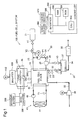
- the fuel gas supply/exhaust system 20 mainly includes a fuel gas supply source (fuel gas tank) 21, a fuel gas supply pipe 22, a fuel gas circulation pipe 24 and a fuel gas exhaust pipe 28.
- the fuel gas tank 21 is structured to store high-pressure fuel gas.
- the fuel gas tank 21 has a shutoff valve V1.
- the fuel gas supply pipe 22 has one end connected to the fuel gas tank 21 and the other end connected to the fuel cell stack 10 (more specifically, a fuel gas supply port (not shown) of the fuel cell stack 10).
- the fuel gas supply port of the fuel cell stack 10 communicates with inner-unit cell fuel gas flow paths via a manifold (not shown) formed in the fuel cell stack 10.
- the fuel gas circulation pipe 24 has one end connected to a fuel gas discharge port (not shown) of the fuel cell stack 10 and the other end connected to the fuel gas supply pipe 22.
- a pressure sensor P1, a hydrogen concentration sensor D1, a gas-liquid separator 25, and a fuel gas circulation pump 26 are provided in the fuel gas circulation pipe 24.
- the pressure sensor P1 measures the internal pressure of the fuel gas circulation pipe 24.
- the hydrogen concentration sensor D1 measures the concentration of hydrogen included in the recirculated gas present in the fuel gas circulation pipe 24.
- the oxidizing gas supply/exhaust system 30 mainly includes an oxidizing gas supply pipe 32 and an oxidizing gas exhaust pipe 33.
- the oxidizing gas supply pipe 32 has one end open to the atmosphere outside the fuel cell system 100 and the other end connected to the fuel cell stack 10 (more specifically, an oxidizing gas supply port (not shown) of the fuel cell stack 10).
- the oxidizing gas supply port of the fuel cell stack 10 communicates with inner-unit cell oxidizing gas flow paths via a manifold (not shown) formed in the fuel cell stack 10.
- the internal pressure measured by the pressure sensor P2 and the hydrogen concentration measured by the hydrogen concentration sensor D2 are used respectively as the pressure in the cathode (hereinafter called “cathode total pressure") of the fuel cell stack 10 and as the hydrogen concentration in the cathode for the pre-stop process described later.
- the exhaust oxidizing gas from the cathode flows through the oxidizing gas exhaust pipe 33 and is introduced into the diluter 37.
- the shutoff valve V1 and the pressure regulator V2 are opened to supply hydrogen to the anode, whilst the fuel gas circulation pump 26 is operated to introduce the exhaust fuel gas into the fuel gas supply pipe 22 and reuse the exhaust fuel gas.
- the air compressor 36 is also operated to supply the oxidizing gas to the cathode, whilst the valve V4 is opened to discharge out the exhaust oxidizing gas.
- the circulation pump 46 is also operated to circulate and deliver cooling water through the fuel cell stack.
- the switches SW1 and SW2 of the load connector 45 are set ON to supply the generated electric power to at least the inverter 400.
- one procedure of determining whether a preset condition is satisfied based on the voltage value may determine whether any one of a plurality of unit cells satisfies the preset condition. Another procedure may classify a plurality of unit cells into multiple groups and determine whether each group satisfies the preset condition, based on the mean value of the group. Yet another procedure may determine whether the preset condition is satisfied, based on the voltage value of an arbitrary unit cell among a plurality of unit cells. Another procedure may determine whether the preset condition is satisfied, based on the overall output voltage of the fuel cell stack.
- the reference value for the hydrogen partial pressure difference is preferably set in a range from 0 to 30 Kpa.
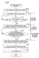
- the process of reducing the partial pressure difference of a gas component between the two electrodes to or below a preset reference value, i.e., step S140, is also called "gas pressure difference reducing process".
- the controller 500 controls the open-close setting of the exhaust valve V3 and the supply amount of the fuel gas by the pressure regulator V2 to prevent a significant variation in hydrogen partial pressure at the anode during the gas delivering process and the gas pressure difference reducing process.
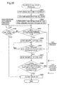
- step S140: No When it is determined that the partial pressure difference between the hydrogen partial pressures in the two electrodes is not reduced to or below the preset reference value (step S140: No), the gas delivering process continues until the hydrogen partial pressure difference between the two electrodes is reduced to or below the preset reference value.
- step S140: Yes On the other hand, the controller 500 closes the valves V1 and V2 and stops the operation of the circulation pump 46 and the fuel gas circulation pump 26 to stop the supply and recirculation of the fuel gas and the circulation of the cooling water (step S150).
- the controller 500 also stops the voltage application from the secondary battery 200 to the fuel cell stack 10 and turns OFF the switch SW2 (step S160) and closes the valve V4 (step S170). This completes the pre-stop process and stops the system.
- the processing of steps S150 and S160 may be performed in no particular order but at any arbitrary timing.
- the operation of the fuel gas circulation pump is stopped at step S150 according to the above embodiment but may alternatively be stopped at any other timing of or after step S110 (e.g., at the timing of step S110).
- the circulation of cooling water is stopped at step S150 according to the above embodiment, but the circulation of cooling water may be started and stopped at any other timing to keep the temperature of the fuel cell stack 10 at the adequate level.
- the oxygen reducing process (steps S110 and S120) is performed prior to the gas delivering process (step S130). This prevents hydrogen delivered to the cathode from reacting with oxygen and combusting on the cathode catalyst, thereby preventing the performance degradation of the fuel cell stack 10.
- the oxygen reducing process (steps S110 and S120) may be omitted from the first and second pre-stop processes. Even in the application with such omission, the gas pressure difference reducing process (step S140 or step S140a) can reduce the variation of the cathode total pressure after the system stop.
- the operation of the fuel gas circulation pump 26 continues at step S110, but may alternatively be stopped.
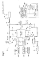
- Fig. 4 illustrates the general configuration of an electric vehicle with a fuel cell system 100a according to a second embodiment of the invention.
- the difference from the first embodiment includes a mechanism of recirculating the exhaust gas that is discharged from the oxidizing gas discharge port of the fuel cell stack 10 to the oxidizing gas exhaust pipe 33 (hereinafter also called "first exhaust gas"), to the cathode as the first gas during the pre-stop process, in addition to the structures of the first embodiment.
- first exhaust gas oxidizing gas exhaust pipe 33
- the second embodiment has the similar configuration to that of the first embodiment.
- the like structures to those of the first embodiment are shown by the like symbols and are not specifically described here.
- step S140a may be replaced with step S140 of the first pre-stop process ( Fig. 2 ).
- Such modified procedure also enables reduction of the variation of the cathode total pressure. Reducing the partial pressure difference of at least hydrogen, which has the higher permeation rate through the electrolyte membrane at a specific partial pressure difference than nitrogen, to or below the preset reference value reduces the variation of the cathode total pressure and prevents negative pressure in the cathode. This prevents introduction of the air from outside the fuel cell stack 10 into the cathode.
- the inventors have found that power generation of the fuel cell stack at the cell temperature of not higher than 0°C and with the smaller air stoichiometric ratio than the air stoichiometric ratio during normal power generation results in performance degradation of the cathode catalyst layer. More specifically, the inventors have found that part of the cathode catalyst layer is peeled off from the electrolyte membrane.
- step S102 may be omitted.
- Such modified procedure still enables at least reduction of the variation of the cathode total pressure and prevention of the oxidation of the cathode component material.
- the secondary battery 200 and the DC-DC converter 300 may be omitted.
- Such modified structure enables the gas delivering process.
- step S104 may be modified to start power generation with setting the stoichiometric ratio of the fuel gas (hereinafter also called “hydrogen stoichiometric ratio”) to be less than the hydrogen stoichiometric ratio during normal power generation, in addition to the smaller air stoichiometric ratio.
- This increases the nitrogen concentration and decreases the hydrogen concentration in the anode (i.e., increases the nitrogen partial pressure and decreases the hydrogen partial pressure in the anode), thus enabling the preset conditions of step S140a to be satisfied within a shorter period of time and shortening the operation time of the pre-stop process.
- the controller 500 subsequently changes over the port open-close settings of the three-way valves V10 and V12 (step S230).
- Such changeover connects the first bypass pipe 74 with the second pipe 32d, while disconnecting the first pipe 32c from the second pipe 32d.
- the changeover also connects the second bypass pipe 76 with the third pipe 33c, while disconnecting the third pipe 33c from the fourth pipe 33d. This forms a circulation delivery path to recirculate and deliver the first gas to the anode and the cathode.
- the sixth pre-stop process delivers the gas of the same composition and the sufficiently reduced concentration variation as the first gas to both the anode and the cathode and thereby readily reduces the partial pressure difference of each gas component between the cathode and the anode to or below the preset reference value without any special control.
- the gas remaining in the fuel gas supply/exhaust system 20 and the oxidizing gas supply/exhaust system 30 is used as the first gas, so that the amount of the first gas used for the pre-stop process can be reduced. This does not require a gas exclusively used for the pre-stop process separately from the reactive gases during normal power generation.
- the sixth pre-stop process performs the gas pressure difference reducing process to reduce the variation of the cathode total pressure and inhibit oxidation of the cathode component material. This also prevents negative pressure in the cathode after the system stop and does not need a mechanism of the high sealing property at the cathode exit, thus enabling cost reduction.
- step S200 the controller 500 stops power generation of the fuel cell stack 10 (step S201a).
- the controller 500 subsequently stops the supply of the oxidizing gas and the fuel gas and the circulation of cooling water (step S202a), while continuing the operation of the fuel gas circulation pump 26.
- the processing of steps S201a and S202a are equivalent to the processing of steps S210 and S220 in the sixth pre-stop process.
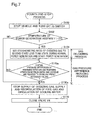
- the controller 500 determines whether the cathode atmosphere has been replaced by hydrogen (step S440). For example, this determination may be based on whether a preset time period has elapsed, wherein this time period represents a period of time required for replacing the cathode atmosphere by hydrogen after opening the relief valve V18 and determined in advance based on the volume of the cathode and the supply amount of hydrogen from the fuel gas tank 21.
- the controller 500 subsequently determines whether the difference between the anode total pressure and the cathode total pressure is reduced to or below a preset value (step S480). When it is determined that the total pressure difference is not reduced to or below the preset value (step S480: No), the determination of step S480 is repeated. With elapse of time, the anode total pressure is gradually reduced to the atmospheric pressure level. When it is determined that the total pressure difference is reduced to or below the preset level (step S480: Yes), on the other hand, the controller 500 closes the exhaust valve V3 and the valve V4 (step S490).
- the exhaust valve V3 may be used in place of the anode exit valve V16. In other words, the anode exit valve V16 may be omitted. In this application, opening and closing the exhaust valve V3 substitute for opening and closing the anode exit valve V16 at step S430 and at step S450. This application ensures the similar advantageous effects to those of the sixth embodiment.
- the third bypass pipe 80 is connected with the oxidizing gas exhaust pipe 33 and the fuel gas circulation pipe 24. More specifically, one end of the third bypass pipe 80 is connected with an upstream section of the oxidizing gas exhaust pipe 33 in the upstream of the valve V4, while the other end is connected with an upstream section of the fuel gas circulation pipe 24 in the upstream of the anode exit valve V16.
- the relief valve V18 is provided in the third bypass pipe, like the sixth embodiment.
- Fig. 19 is a flowchart showing a tenth aspect of pre-stop process (hereinafter called "tenth pre-stop process”) performed by the controller 500 according to the first modification embodiment.
- the difference from the ninth pre-stop process includes a series of processing after step S430.
- the like steps to those of the ninth pre-stop process are shown by the like step numbers and are not specifically described here.
- the tenth pre-stop process fills the oxidizing gas exhaust pipe 33 with hydrogen and thereby prevents introduction of oxygen to the cathode even when negative pressure is generated in the cathode after the system stop. This advantageously inhibits oxidation of the cathode component material.
- the exhaust valve V3 may be used in place of the anode exit valve V16. In other words, the anode exit valve V16 may be omitted.
- step S630 determines whether a preset time period has elapsed since the stop of power generation (step S640). When it is determined that the preset time period has not yet elapsed (step S640: No), the determination of step S630 is repeated. When it is determined that the preset time period has elapsed (step S640: Yes), the controller 500 closes the valve V4 and terminates the pre-stop process. The pre-stop process is terminated on elapse of the preset time period, because of the following reason.
- the controller 500 subsequently determines whether the anode total pressure reaches or exceeds a second reference value (step S660). When it is determined that the anode total pressure does not reach or exceed the second reference value (step S660: No), the resupply of the fuel gas continues. When it is determined that the anode total pressure reaches or exceeds the second reference value (step S660: Yes), on the other hand, the controller 500 stops the resupply of the fuel gas (step S670). At step S670, the recirculation of the fuel gas by the fuel gas circulation pump 26 is also stopped.
- the second reference value may be set in a range that prevents deformation of the electrolyte membrane due to the total pressure difference between the two electrodes.
- one end of the return pipe 29 is connected with the diluter 37.
- This structure is, however, not essential, and any other structure may be employed as the mechanism to further agitate the gas.
- one end of the return pipe 29 may be connected with the muffler 38.
- This structure also ensures sufficient agitation of the gas.
- the fuel gas supply pipe 22 may be structured to have a larger-diameter part or a baffle plate may be provided in the anode manifold of the fuel cell stack 140, through which the fuel gas flows.
Landscapes
- Life Sciences & Earth Sciences (AREA)
- Sustainable Development (AREA)
- Engineering & Computer Science (AREA)
- Manufacturing & Machinery (AREA)
- Sustainable Energy (AREA)
- Chemical & Material Sciences (AREA)
- Chemical Kinetics & Catalysis (AREA)
- Electrochemistry (AREA)
- General Chemical & Material Sciences (AREA)
- Fuel Cell (AREA)
Applications Claiming Priority (1)
| Application Number | Priority Date | Filing Date | Title |
|---|---|---|---|
| PCT/JP2009/005214 WO2011042932A1 (fr) | 2009-10-07 | 2009-10-07 | Système de pile à combustible et procédé pour arrêter un système de pile à combustible |
Publications (3)
| Publication Number | Publication Date |
|---|---|
| EP2487740A1 true EP2487740A1 (fr) | 2012-08-15 |
| EP2487740A4 EP2487740A4 (fr) | 2013-12-18 |
| EP2487740B1 EP2487740B1 (fr) | 2016-01-06 |
Family
ID=43856437
Family Applications (1)
| Application Number | Title | Priority Date | Filing Date |
|---|---|---|---|
| EP09850209.9A Not-in-force EP2487740B1 (fr) | 2009-10-07 | 2009-10-07 | Système de pile à combustible et procédé pour arrêter un système de pile à combustible |
Country Status (7)
| Country | Link |
|---|---|
| US (1) | US8932772B2 (fr) |
| EP (1) | EP2487740B1 (fr) |
| JP (1) | JP5293830B2 (fr) |
| KR (1) | KR101321429B1 (fr) |
| CN (1) | CN102668209B (fr) |
| CA (1) | CA2776982C (fr) |
| WO (1) | WO2011042932A1 (fr) |
Cited By (2)
| Publication number | Priority date | Publication date | Assignee | Title |
|---|---|---|---|---|
| EP3021404A1 (fr) * | 2014-11-12 | 2016-05-18 | Toyota Jidosha Kabushiki Kaisha | Système de pile à combustible et véhicule équipé d'une pile à combustible |
| WO2017089010A1 (fr) * | 2015-11-23 | 2017-06-01 | Robert Bosch Gmbh | Pile à combustible |
Families Citing this family (21)
| Publication number | Priority date | Publication date | Assignee | Title |
|---|---|---|---|---|
| US8642223B2 (en) * | 2011-06-14 | 2014-02-04 | GM Global Technology Operations LLC | Control strategy to prevent unexpected hydrogen flow to the cathode due to a failed pressure sensor while catalytic heating |
| CN104487141A (zh) * | 2012-03-19 | 2015-04-01 | 祖迪雅克航空技术公司 | 用于防火和/或防爆的燃料电池装置 |
| EP2772976B1 (fr) * | 2013-02-27 | 2017-11-15 | Airbus Defence and Space GmbH | Système régénératif de piles à combustible avec purification de gaz |
| US9906039B2 (en) | 2013-03-14 | 2018-02-27 | Combind Energies, LLC | Power system for multiple power sources |
| US9960438B2 (en) * | 2013-03-14 | 2018-05-01 | Ford Global Technologies, Llc | Fuel cell system and method to prevent water-induced damage |
| US20140278709A1 (en) | 2013-03-14 | 2014-09-18 | Combined Energies LLC | Intelligent CCHP System |
| JP5744094B2 (ja) * | 2013-03-27 | 2015-07-01 | 本田技研工業株式会社 | 燃料電池システムの制御方法 |
| KR101551024B1 (ko) * | 2013-12-23 | 2015-09-08 | 현대자동차주식회사 | 연료 전지 시스템의 시동 제어 방법 |
| JP6472638B2 (ja) * | 2014-10-30 | 2019-02-20 | 三菱日立パワーシステムズ株式会社 | 複合発電システム、その制御装置及び方法並びにプログラム |
| DE102015209115A1 (de) * | 2015-05-19 | 2016-11-24 | Volkswagen Ag | Brennstoffzellensystem |
| DE102015216343A1 (de) | 2015-08-26 | 2017-03-02 | Volkswagen Aktiengesellschaft | Anoden-Kathoden-Versorgungseinrichtung |
| CN108432015B (zh) * | 2015-12-25 | 2021-06-11 | 日产自动车株式会社 | 燃料电池系统和燃料电池系统的控制方法 |
| JP7029630B2 (ja) * | 2016-12-15 | 2022-03-04 | パナソニックIpマネジメント株式会社 | 燃料電池システム |
| KR102129013B1 (ko) * | 2017-12-15 | 2020-07-01 | (주)엠텍정보기술 | 하이브리드 연료전지 파워팩 |
| JP6897626B2 (ja) * | 2018-04-12 | 2021-06-30 | トヨタ自動車株式会社 | 燃料電池システム及び金属イオン含有量の推定方法 |
| KR102598947B1 (ko) * | 2018-05-04 | 2023-11-06 | 현대자동차주식회사 | 연료전지 시스템 및 그의 제어방법 |
| JP7108822B2 (ja) * | 2018-07-05 | 2022-07-29 | パナソニックIpマネジメント株式会社 | 燃料電池システム並びにその運転方法 |
| KR20200071255A (ko) * | 2018-12-11 | 2020-06-19 | 현대자동차주식회사 | 연료전지 시스템의 수소 공급 제어 방법 |
| US11824238B2 (en) | 2019-04-30 | 2023-11-21 | Hyaxiom, Inc. | System for managing hydrogen utilization in a fuel cell power plant |
| JP7211400B2 (ja) * | 2020-06-26 | 2023-01-24 | トヨタ自動車株式会社 | 燃料電池システム |
| US11768186B2 (en) | 2020-12-08 | 2023-09-26 | Hyaxiom, Inc. | Hydrogen concentration sensor |
Citations (2)
| Publication number | Priority date | Publication date | Assignee | Title |
|---|---|---|---|---|
| JPS61116764A (ja) * | 1984-11-12 | 1986-06-04 | Toshiba Corp | 燃料電池装置 |
| US20080182138A1 (en) * | 2007-01-31 | 2008-07-31 | Gm Global Technology Operations, Inc. | Strategies for Mitigating Cell Degradation During Start-Up and Shutdown with H2/N2 Storage |
Family Cites Families (10)
| Publication number | Priority date | Publication date | Assignee | Title |
|---|---|---|---|---|
| DE3102140A1 (de) | 1981-01-23 | 1982-08-19 | Bayer Ag, 5090 Leverkusen | Formteil, insbesondere polster fuer fahrzeugsitze, aus polyurethanschaumstoff mit zonen unterschiedlicher eindruckhaerte und verfahren zu seiner herstellung |
| JPH10321248A (ja) * | 1997-05-22 | 1998-12-04 | Matsushita Electric Works Ltd | 燃料電池発電システム |
| US6329089B1 (en) | 1997-12-23 | 2001-12-11 | Ballard Power Systems Inc. | Method and apparatus for increasing the temperature of a fuel cell |
| JP3863042B2 (ja) * | 2002-03-20 | 2006-12-27 | 東芝燃料電池システム株式会社 | 燃料電池の再活性化処理方法およびそのシステム |
| JP4028363B2 (ja) | 2002-11-28 | 2007-12-26 | 本田技研工業株式会社 | 燃料電池システムの発電停止方法 |
| JP4417068B2 (ja) * | 2003-10-06 | 2010-02-17 | 本田技研工業株式会社 | 燃料電池の停止方法 |
| JP2006066107A (ja) | 2004-08-24 | 2006-03-09 | Matsushita Electric Ind Co Ltd | 燃料電池システム、燃料電池システムの停止方法 |
| JP4907861B2 (ja) * | 2004-11-17 | 2012-04-04 | 東芝燃料電池システム株式会社 | 燃料電池発電システムとその停止保管方法、停止保管プログラム |
| JP2007109529A (ja) * | 2005-10-14 | 2007-04-26 | Mitsubishi Electric Corp | 燃料電池発電システムの制御方法 |
| JP2007157530A (ja) * | 2005-12-06 | 2007-06-21 | Nissan Motor Co Ltd | 燃料電池システム |
-
2009
- 2009-10-07 CA CA2776982A patent/CA2776982C/fr active Active
- 2009-10-07 KR KR1020127011749A patent/KR101321429B1/ko active IP Right Grant
- 2009-10-07 US US13/500,736 patent/US8932772B2/en active Active
- 2009-10-07 EP EP09850209.9A patent/EP2487740B1/fr not_active Not-in-force
- 2009-10-07 CN CN200980161862.XA patent/CN102668209B/zh not_active Expired - Fee Related
- 2009-10-07 WO PCT/JP2009/005214 patent/WO2011042932A1/fr active Application Filing
- 2009-10-07 JP JP2011535216A patent/JP5293830B2/ja active Active
Patent Citations (2)
| Publication number | Priority date | Publication date | Assignee | Title |
|---|---|---|---|---|
| JPS61116764A (ja) * | 1984-11-12 | 1986-06-04 | Toshiba Corp | 燃料電池装置 |
| US20080182138A1 (en) * | 2007-01-31 | 2008-07-31 | Gm Global Technology Operations, Inc. | Strategies for Mitigating Cell Degradation During Start-Up and Shutdown with H2/N2 Storage |
Non-Patent Citations (1)
| Title |
|---|
| See also references of WO2011042932A1 * |
Cited By (3)
| Publication number | Priority date | Publication date | Assignee | Title |
|---|---|---|---|---|
| EP3021404A1 (fr) * | 2014-11-12 | 2016-05-18 | Toyota Jidosha Kabushiki Kaisha | Système de pile à combustible et véhicule équipé d'une pile à combustible |
| US10573908B2 (en) | 2014-11-12 | 2020-02-25 | Toyota Jidosha Kabushiki Kaisha | Fuel cell system and vehicle equipped with fuel cell |
| WO2017089010A1 (fr) * | 2015-11-23 | 2017-06-01 | Robert Bosch Gmbh | Pile à combustible |
Also Published As
| Publication number | Publication date |
|---|---|
| CN102668209A (zh) | 2012-09-12 |
| US8932772B2 (en) | 2015-01-13 |
| EP2487740A4 (fr) | 2013-12-18 |
| CA2776982C (fr) | 2013-12-31 |
| CN102668209B (zh) | 2015-04-08 |
| JP5293830B2 (ja) | 2013-09-18 |
| JPWO2011042932A1 (ja) | 2013-02-28 |
| EP2487740B1 (fr) | 2016-01-06 |
| KR20120062932A (ko) | 2012-06-14 |
| KR101321429B1 (ko) | 2013-10-28 |
| US20120276460A1 (en) | 2012-11-01 |
| CA2776982A1 (fr) | 2011-04-14 |
| WO2011042932A1 (fr) | 2011-04-14 |
Similar Documents
| Publication | Publication Date | Title |
|---|---|---|
| CA2776982C (fr) | Commande de systeme de piles a combustible comprenant une detection de pression partielle de n2 et de h2 | |
| JP4868251B2 (ja) | 燃料電池システム、アノードガス生成量推定装置及びアノードガス生成量の推定方法 | |
| US20080318098A1 (en) | Fuel Cell System and Driving Method of Fuel Cell System | |
| US10038205B2 (en) | Fuel cell system | |
| US8227123B2 (en) | Fuel cell system and current control method with PI compensation based on minimum cell voltage | |
| JP5155734B2 (ja) | 燃料電池システム及びその運転方法 | |
| US9093679B2 (en) | Method of shutting down fuel cell system | |
| JP5224082B2 (ja) | 燃料電池システム及びその排水制御方法 | |
| WO2005088754A1 (fr) | Dispositif de commande pour système à cellule électrochimique | |
| US8394517B2 (en) | Fuel cell system and control method of the system | |
| WO2008050881A1 (fr) | Système de pile à combustible | |
| WO2006030969A1 (fr) | Systeme de piles a combustible et procede de determination de fuite de gaz pour systeme de piles a combustible | |
| US8053124B2 (en) | Fuel cell system and mobile body | |
| JP2005183354A (ja) | 燃料電池システム | |
| WO2005096428A1 (fr) | Système de pile à combustible et méthode de contrôle de celui-ci | |
| KR20070084599A (ko) | 연료전지시스템과 그 운전방법 및 연료전지 차량 | |
| US8691460B2 (en) | Method of stopping operation of fuel cell system | |
| JP5299211B2 (ja) | 燃料電池システムおよびその停止方法 | |
| US9070916B2 (en) | Method for controlling fuel cell system | |
| JP2009295505A (ja) | 燃料電池システム | |
| JP2005158553A (ja) | 燃料電池システム | |
| US8241804B1 (en) | Method for controlling fuel cell system | |
| US8252471B2 (en) | Fuel cell system | |
| EP2056387B1 (fr) | Système de piles à combustible et procédé de purge correspondant | |
| JP2005129243A (ja) | 燃料電池システムおよび燃料電池の運転方法 |
Legal Events
| Date | Code | Title | Description |
|---|---|---|---|
| PUAI | Public reference made under article 153(3) epc to a published international application that has entered the european phase |
Free format text: ORIGINAL CODE: 0009012 |
|
| 17P | Request for examination filed |
Effective date: 20120405 |
|
| AK | Designated contracting states |
Kind code of ref document: A1 Designated state(s): AT BE BG CH CY CZ DE DK EE ES FI FR GB GR HR HU IE IS IT LI LT LU LV MC MK MT NL NO PL PT RO SE SI SK SM TR |
|
| DAX | Request for extension of the european patent (deleted) | ||
| RAP1 | Party data changed (applicant data changed or rights of an application transferred) |
Owner name: TOYOTA JIDOSHA KABUSHIKI KAISHA |
|
| A4 | Supplementary search report drawn up and despatched |
Effective date: 20131118 |
|
| RIC1 | Information provided on ipc code assigned before grant |
Ipc: H01M 8/04 20060101AFI20131112BHEP Ipc: H01M 8/10 20060101ALI20131112BHEP |
|
| 17Q | First examination report despatched |
Effective date: 20141208 |
|
| GRAP | Despatch of communication of intention to grant a patent |
Free format text: ORIGINAL CODE: EPIDOSNIGR1 |
|
| INTG | Intention to grant announced |
Effective date: 20150710 |
|
| GRAS | Grant fee paid |
Free format text: ORIGINAL CODE: EPIDOSNIGR3 |
|
| GRAA | (expected) grant |
Free format text: ORIGINAL CODE: 0009210 |
|
| AK | Designated contracting states |
Kind code of ref document: B1 Designated state(s): AT BE BG CH CY CZ DE DK EE ES FI FR GB GR HR HU IE IS IT LI LT LU LV MC MK MT NL NO PL PT RO SE SI SK SM TR |
|
| REG | Reference to a national code |
Ref country code: GB Ref legal event code: FG4D |
|
| REG | Reference to a national code |
Ref country code: CH Ref legal event code: EP |
|
| REG | Reference to a national code |
Ref country code: IE Ref legal event code: FG4D |
|
| REG | Reference to a national code |
Ref country code: AT Ref legal event code: REF Ref document number: 769549 Country of ref document: AT Kind code of ref document: T Effective date: 20160215 |
|
| REG | Reference to a national code |
Ref country code: DE Ref legal event code: R096 Ref document number: 602009035752 Country of ref document: DE |
|
| REG | Reference to a national code |
Ref country code: LT Ref legal event code: MG4D |
|
| REG | Reference to a national code |
Ref country code: NL Ref legal event code: MP Effective date: 20160106 |
|
| REG | Reference to a national code |
Ref country code: AT Ref legal event code: MK05 Ref document number: 769549 Country of ref document: AT Kind code of ref document: T Effective date: 20160106 |
|
| PG25 | Lapsed in a contracting state [announced via postgrant information from national office to epo] |
Ref country code: NL Free format text: LAPSE BECAUSE OF FAILURE TO SUBMIT A TRANSLATION OF THE DESCRIPTION OR TO PAY THE FEE WITHIN THE PRESCRIBED TIME-LIMIT Effective date: 20160106 |
|
| PG25 | Lapsed in a contracting state [announced via postgrant information from national office to epo] |
Ref country code: FI Free format text: LAPSE BECAUSE OF FAILURE TO SUBMIT A TRANSLATION OF THE DESCRIPTION OR TO PAY THE FEE WITHIN THE PRESCRIBED TIME-LIMIT Effective date: 20160106 Ref country code: IT Free format text: LAPSE BECAUSE OF FAILURE TO SUBMIT A TRANSLATION OF THE DESCRIPTION OR TO PAY THE FEE WITHIN THE PRESCRIBED TIME-LIMIT Effective date: 20160106 Ref country code: GR Free format text: LAPSE BECAUSE OF FAILURE TO SUBMIT A TRANSLATION OF THE DESCRIPTION OR TO PAY THE FEE WITHIN THE PRESCRIBED TIME-LIMIT Effective date: 20160407 Ref country code: ES Free format text: LAPSE BECAUSE OF FAILURE TO SUBMIT A TRANSLATION OF THE DESCRIPTION OR TO PAY THE FEE WITHIN THE PRESCRIBED TIME-LIMIT Effective date: 20160106 Ref country code: NO Free format text: LAPSE BECAUSE OF FAILURE TO SUBMIT A TRANSLATION OF THE DESCRIPTION OR TO PAY THE FEE WITHIN THE PRESCRIBED TIME-LIMIT Effective date: 20160406 Ref country code: HR Free format text: LAPSE BECAUSE OF FAILURE TO SUBMIT A TRANSLATION OF THE DESCRIPTION OR TO PAY THE FEE WITHIN THE PRESCRIBED TIME-LIMIT Effective date: 20160106 |
|
| REG | Reference to a national code |
Ref country code: DE Ref legal event code: R084 Ref document number: 602009035752 Country of ref document: DE |
|
| PG25 | Lapsed in a contracting state [announced via postgrant information from national office to epo] |
Ref country code: AT Free format text: LAPSE BECAUSE OF FAILURE TO SUBMIT A TRANSLATION OF THE DESCRIPTION OR TO PAY THE FEE WITHIN THE PRESCRIBED TIME-LIMIT Effective date: 20160106 Ref country code: SE Free format text: LAPSE BECAUSE OF FAILURE TO SUBMIT A TRANSLATION OF THE DESCRIPTION OR TO PAY THE FEE WITHIN THE PRESCRIBED TIME-LIMIT Effective date: 20160106 Ref country code: LV Free format text: LAPSE BECAUSE OF FAILURE TO SUBMIT A TRANSLATION OF THE DESCRIPTION OR TO PAY THE FEE WITHIN THE PRESCRIBED TIME-LIMIT Effective date: 20160106 Ref country code: PT Free format text: LAPSE BECAUSE OF FAILURE TO SUBMIT A TRANSLATION OF THE DESCRIPTION OR TO PAY THE FEE WITHIN THE PRESCRIBED TIME-LIMIT Effective date: 20160506 Ref country code: LT Free format text: LAPSE BECAUSE OF FAILURE TO SUBMIT A TRANSLATION OF THE DESCRIPTION OR TO PAY THE FEE WITHIN THE PRESCRIBED TIME-LIMIT Effective date: 20160106 Ref country code: PL Free format text: LAPSE BECAUSE OF FAILURE TO SUBMIT A TRANSLATION OF THE DESCRIPTION OR TO PAY THE FEE WITHIN THE PRESCRIBED TIME-LIMIT Effective date: 20160106 Ref country code: IS Free format text: LAPSE BECAUSE OF FAILURE TO SUBMIT A TRANSLATION OF THE DESCRIPTION OR TO PAY THE FEE WITHIN THE PRESCRIBED TIME-LIMIT Effective date: 20160506 |
|
| REG | Reference to a national code |
Ref country code: DE Ref legal event code: R097 Ref document number: 602009035752 Country of ref document: DE |
|
| PG25 | Lapsed in a contracting state [announced via postgrant information from national office to epo] |
Ref country code: DK Free format text: LAPSE BECAUSE OF FAILURE TO SUBMIT A TRANSLATION OF THE DESCRIPTION OR TO PAY THE FEE WITHIN THE PRESCRIBED TIME-LIMIT Effective date: 20160106 Ref country code: EE Free format text: LAPSE BECAUSE OF FAILURE TO SUBMIT A TRANSLATION OF THE DESCRIPTION OR TO PAY THE FEE WITHIN THE PRESCRIBED TIME-LIMIT Effective date: 20160106 |
|
| PLBE | No opposition filed within time limit |
Free format text: ORIGINAL CODE: 0009261 |
|
| STAA | Information on the status of an ep patent application or granted ep patent |
Free format text: STATUS: NO OPPOSITION FILED WITHIN TIME LIMIT |
|
| PG25 | Lapsed in a contracting state [announced via postgrant information from national office to epo] |
Ref country code: SK Free format text: LAPSE BECAUSE OF FAILURE TO SUBMIT A TRANSLATION OF THE DESCRIPTION OR TO PAY THE FEE WITHIN THE PRESCRIBED TIME-LIMIT Effective date: 20160106 Ref country code: SM Free format text: LAPSE BECAUSE OF FAILURE TO SUBMIT A TRANSLATION OF THE DESCRIPTION OR TO PAY THE FEE WITHIN THE PRESCRIBED TIME-LIMIT Effective date: 20160106 Ref country code: CZ Free format text: LAPSE BECAUSE OF FAILURE TO SUBMIT A TRANSLATION OF THE DESCRIPTION OR TO PAY THE FEE WITHIN THE PRESCRIBED TIME-LIMIT Effective date: 20160106 Ref country code: RO Free format text: LAPSE BECAUSE OF FAILURE TO SUBMIT A TRANSLATION OF THE DESCRIPTION OR TO PAY THE FEE WITHIN THE PRESCRIBED TIME-LIMIT Effective date: 20160106 |
|
| 26N | No opposition filed |
Effective date: 20161007 |
|
| PG25 | Lapsed in a contracting state [announced via postgrant information from national office to epo] |
Ref country code: BE Free format text: LAPSE BECAUSE OF FAILURE TO SUBMIT A TRANSLATION OF THE DESCRIPTION OR TO PAY THE FEE WITHIN THE PRESCRIBED TIME-LIMIT Effective date: 20160106 |
|
| PG25 | Lapsed in a contracting state [announced via postgrant information from national office to epo] |
Ref country code: SI Free format text: LAPSE BECAUSE OF FAILURE TO SUBMIT A TRANSLATION OF THE DESCRIPTION OR TO PAY THE FEE WITHIN THE PRESCRIBED TIME-LIMIT Effective date: 20160106 Ref country code: BG Free format text: LAPSE BECAUSE OF FAILURE TO SUBMIT A TRANSLATION OF THE DESCRIPTION OR TO PAY THE FEE WITHIN THE PRESCRIBED TIME-LIMIT Effective date: 20160406 |
|
| REG | Reference to a national code |
Ref country code: CH Ref legal event code: PL |
|
| GBPC | Gb: european patent ceased through non-payment of renewal fee |
Effective date: 20161007 |
|
| REG | Reference to a national code |
Ref country code: IE Ref legal event code: MM4A |
|
| REG | Reference to a national code |
Ref country code: FR Ref legal event code: ST Effective date: 20170630 |
|
| PG25 | Lapsed in a contracting state [announced via postgrant information from national office to epo] |
Ref country code: GB Free format text: LAPSE BECAUSE OF NON-PAYMENT OF DUE FEES Effective date: 20161007 Ref country code: LI Free format text: LAPSE BECAUSE OF NON-PAYMENT OF DUE FEES Effective date: 20161031 Ref country code: FR Free format text: LAPSE BECAUSE OF NON-PAYMENT OF DUE FEES Effective date: 20161102 Ref country code: CH Free format text: LAPSE BECAUSE OF NON-PAYMENT OF DUE FEES Effective date: 20161031 |
|
| PG25 | Lapsed in a contracting state [announced via postgrant information from national office to epo] |
Ref country code: LU Free format text: LAPSE BECAUSE OF NON-PAYMENT OF DUE FEES Effective date: 20161007 |
|
| PG25 | Lapsed in a contracting state [announced via postgrant information from national office to epo] |
Ref country code: IE Free format text: LAPSE BECAUSE OF NON-PAYMENT OF DUE FEES Effective date: 20161007 |
|
| PG25 | Lapsed in a contracting state [announced via postgrant information from national office to epo] |
Ref country code: CY Free format text: LAPSE BECAUSE OF FAILURE TO SUBMIT A TRANSLATION OF THE DESCRIPTION OR TO PAY THE FEE WITHIN THE PRESCRIBED TIME-LIMIT Effective date: 20160106 Ref country code: HU Free format text: LAPSE BECAUSE OF FAILURE TO SUBMIT A TRANSLATION OF THE DESCRIPTION OR TO PAY THE FEE WITHIN THE PRESCRIBED TIME-LIMIT; INVALID AB INITIO Effective date: 20091007 |
|
| PG25 | Lapsed in a contracting state [announced via postgrant information from national office to epo] |
Ref country code: MT Free format text: LAPSE BECAUSE OF NON-PAYMENT OF DUE FEES Effective date: 20161031 Ref country code: MC Free format text: LAPSE BECAUSE OF FAILURE TO SUBMIT A TRANSLATION OF THE DESCRIPTION OR TO PAY THE FEE WITHIN THE PRESCRIBED TIME-LIMIT Effective date: 20160106 Ref country code: TR Free format text: LAPSE BECAUSE OF FAILURE TO SUBMIT A TRANSLATION OF THE DESCRIPTION OR TO PAY THE FEE WITHIN THE PRESCRIBED TIME-LIMIT Effective date: 20160106 Ref country code: MK Free format text: LAPSE BECAUSE OF FAILURE TO SUBMIT A TRANSLATION OF THE DESCRIPTION OR TO PAY THE FEE WITHIN THE PRESCRIBED TIME-LIMIT Effective date: 20160106 |
|
| PGFP | Annual fee paid to national office [announced via postgrant information from national office to epo] |
Ref country code: DE Payment date: 20210831 Year of fee payment: 13 |
|
| REG | Reference to a national code |
Ref country code: DE Ref legal event code: R119 Ref document number: 602009035752 Country of ref document: DE |
|
| PG25 | Lapsed in a contracting state [announced via postgrant information from national office to epo] |
Ref country code: DE Free format text: LAPSE BECAUSE OF NON-PAYMENT OF DUE FEES Effective date: 20230503 |