EP2484561A1 - Agencement de pare-chocs - Google Patents
Agencement de pare-chocs Download PDFInfo
- Publication number
- EP2484561A1 EP2484561A1 EP12151494A EP12151494A EP2484561A1 EP 2484561 A1 EP2484561 A1 EP 2484561A1 EP 12151494 A EP12151494 A EP 12151494A EP 12151494 A EP12151494 A EP 12151494A EP 2484561 A1 EP2484561 A1 EP 2484561A1
- Authority
- EP
- European Patent Office
- Prior art keywords
- cross member
- sheet metal
- metal component
- vehicle bumper
- bumper arrangement
- Prior art date
- Legal status (The legal status is an assumption and is not a legal conclusion. Google has not performed a legal analysis and makes no representation as to the accuracy of the status listed.)
- Granted
Links
Images


Classifications
-
- B—PERFORMING OPERATIONS; TRANSPORTING
- B60—VEHICLES IN GENERAL
- B60R—VEHICLES, VEHICLE FITTINGS, OR VEHICLE PARTS, NOT OTHERWISE PROVIDED FOR
- B60R19/00—Wheel guards; Radiator guards, e.g. grilles; Obstruction removers; Fittings damping bouncing force in collisions
- B60R19/02—Bumpers, i.e. impact receiving or absorbing members for protecting vehicles or fending off blows from other vehicles or objects
- B60R19/18—Bumpers, i.e. impact receiving or absorbing members for protecting vehicles or fending off blows from other vehicles or objects characterised by the cross-section; Means within the bumper to absorb impact
-
- B—PERFORMING OPERATIONS; TRANSPORTING
- B60—VEHICLES IN GENERAL
- B60R—VEHICLES, VEHICLE FITTINGS, OR VEHICLE PARTS, NOT OTHERWISE PROVIDED FOR
- B60R19/00—Wheel guards; Radiator guards, e.g. grilles; Obstruction removers; Fittings damping bouncing force in collisions
- B60R19/02—Bumpers, i.e. impact receiving or absorbing members for protecting vehicles or fending off blows from other vehicles or objects
- B60R19/03—Bumpers, i.e. impact receiving or absorbing members for protecting vehicles or fending off blows from other vehicles or objects characterised by material, e.g. composite
-
- B—PERFORMING OPERATIONS; TRANSPORTING
- B60—VEHICLES IN GENERAL
- B60R—VEHICLES, VEHICLE FITTINGS, OR VEHICLE PARTS, NOT OTHERWISE PROVIDED FOR
- B60R19/00—Wheel guards; Radiator guards, e.g. grilles; Obstruction removers; Fittings damping bouncing force in collisions
- B60R19/02—Bumpers, i.e. impact receiving or absorbing members for protecting vehicles or fending off blows from other vehicles or objects
- B60R19/18—Bumpers, i.e. impact receiving or absorbing members for protecting vehicles or fending off blows from other vehicles or objects characterised by the cross-section; Means within the bumper to absorb impact
- B60R2019/1806—Structural beams therefor, e.g. shock-absorbing
- B60R2019/1813—Structural beams therefor, e.g. shock-absorbing made of metal
- B60R2019/182—Structural beams therefor, e.g. shock-absorbing made of metal of light metal, e.g. extruded
Definitions
- the present invention relates to a motor vehicle bumper arrangement having a cross member coupled via crash boxes to longitudinal members according to the features in the preamble of patent claim 1.
- the structure of a motor vehicle usually has numerous carriers whose profiles have a constant cross-section. These carriers serve to absorb tensile forces whose amplitudes and directions are variable. However, some carriers are designed to absorb the maximum amount of energy when applied with a force from a given direction. Bumpers are commonly known from the prior art at the front and rear of a motor vehicle for absorbing and dissipation of impact energy.
- the structure takes place here via a cross member, which is usually coupled to the body via crash boxes. Often this is the cross member coupled via the crash boxes with longitudinal members of the body.
- bumper systems or cross member made of tempered or high-strength steels, or it is also used on aluminum materials.
- the balancing act must be performed between the manufacturer's own design requirements as well as legal and manufacturer's own safety requirements.
- these are often equipped in the area of the front or the rear with a front or rear apron made of plastic.
- the shape of the respective aprons also give the shape of the underlying cross member. So that no effective overhang is wasted, there is a requirement for the cross member to be arranged as close as possible behind the apron. Overall, however, the overhangs and associated with keeping the total vehicle length low, so that the space can be better used in favor of drive components or the passenger compartment.
- the cross member Due to more modern technology, such as passive and active safety and comfort systems, such as distance sensors, parking sensors, video surveillance while driving or the like, the cross member must be elaborately formed, bent, embossed, trimmed, perforated or mechanically processed in any other way , These manufacturing processes make the bumper systems expensive. Also in the Rear area due to exhaust or due to longevity aspects, the bumper assemblies are subjected in addition to a chemical or physical treatment, especially if they are made of steel.
- crashrelevante requirements are set so that they, for example, in low-speed or high-speed tests, in collisions with a pedestrian or other conceivable crash requirements each show the best possible crash performance properties.
- it often comes to a bending of the cross member and thus to a bending of the crash boxes to the outside.
- the connection points of the crash boxes are often leveraged by only small forces, so that the entire path available for Crash energieabbau no longer exists.
- Object of the present invention is therefore, starting from the prior art, to provide a vehicle bumper assembly which has a low weight and a simple construction, at the same time good crash characteristics and particularly favorable producibility.
- the motor vehicle bumper arrangement according to the invention with a cross member coupled via crash boxes to longitudinal members, wherein the cross member consists of a straight extruded profile, is inventively characterized in that on the side opposite the crash boxes opposite side of the cross member, a sheet metal component is coupled to the cross member and the cross member as a multi-chamber hollow profile a light metal is formed.
- the sheet metal component has an arc shape running in its longitudinal direction.
- the sheet metal component is substantially as long as at least in the vehicle transverse direction to see the same time with the cross member. It can also be shorter or longer.
- the sheet metal component itself may be formed as a cold-formed, metallic component or else as a hot-formed and press-hardened component. Likewise, a light metal alloy for producing the sheet metal component can be used.
- the cross member is made of a light metal extruded profile.
- the extruded profile has already through the manufacturing process on a straight or straight course. It is a multi-chamber hollow profile. A complicated stretch bending or other mechanical forming or reworking of the cross member is eliminated.
- the extruded profile according to the invention can be adapted directly to the desired crash stiffnesses in the manufacturing process.
- the multi-chamber hollow profile has high stiffness values, in particular in the event of a crash, while at the same time having a low dead weight.
- the light metal is preferably aluminum or magnesium.
- the production process by means of extrusion offers the advantage that the cross member is suspended and thus is particularly inexpensive to produce, at the same time high crash properties and low weight.
- a post-processing or forming operation which reduces the crash properties is eliminated. Since modern motor vehicles to achieve low cw values and to obtain shapely design specifications often at the front or rear have a curved shape, in particular a curved shape in the vehicle transverse direction, remaining between the rectilinear extruded profile and a plastic outer skin space or distance by an additional Bridged sheet metal component, which is coupled to the cross member.
- the sheet metal component is arranged front side in the direction of travel in front of the cross member and the rear side in the direction of travel behind the cross member.
- This sheet metal part can for example be welded or else screwed to the cross member or the crash boxes. Also, a riveting or other joining method is possible.
- the motor vehicle bumper arrangement according to the invention can be optimally adapted to the respective crash requirement.
- the motor vehicle bumper assembly according to the invention taking into account the production tolerances particularly dimensionally stable and at the same time very inexpensive to produce.
- the use of high-strength materials, in particular high-strength or quenched metal or light metal materials possible, especially on the components that are no expensive forming operations for shaping.
- the cross member and the sheet metal component are cohesively and / or positively coupled, in particular via a screw connection and / or welded connection.
- the cohesive coupling allows a particularly cost-effective production, but is limited by the choice of material properties.
- the motor vehicle bumper assembly according to the invention may be positively coupled or even cohesively, for example by a welding brazing. This can be produced, for example, by a form-fitting overlapping and latching or other form-fitting possibilities.
- a screw is selected as a positive coupling option. Via the screw connection, it is additionally possible to carry out a particularly quick and cost-effective repair in case of repair. In particular, since in light rear-end collisions, the additional sheet-metal component can be exchanged with a curved course.
- the motor vehicle bumper arrangement according to the invention is particularly suitable for the production of a system that has a high crash performance with at the same time low dead weight.
- the cross member is preferably formed of a light metal and / or the sheet metal component made of a steel alloy.
- these are furthermore particularly preferably tempered.
- the sheet metal component can be produced by means of hot forming and press hardening. The use of ultrahigh-strength steels is thereby made possible. Both components can be tempered separately or otherwise treated. For example, a partial heat treatment and / or painting or coating is possible.
- the sheet metal component overlaps the cross member at the end.
- the sheet metal component in the vehicle transverse direction on the cross member protrudes end.
- the sheet metal component may be formed in particular from high-strength steel, so that a derivation is particularly well done.
- the sheet metal component preferably has a curvature directed towards the motor vehicle at the end in each case.
- the curvature has in particular a smaller radius than the radius of the arcuate course.
- the sheet metal component itself is in particular more than 5, preferably more than 10 and particularly preferred more than 15 centimeters each in the vehicle transverse direction on the outside above the cross member.
- the sheet metal component is configured in cross-section C-shaped or configured hat-shaped in cross-section. This ensures that the sheet metal component overlaps or covers the cross member in a form-fitting manner and at the same time has a high inherent rigidity against bending and torsion.
- the sheet metal component is particularly preferably designed at least on the end sides of the cross member such that it covers or overlaps it at least in sections.
- the legs of the C-shaped or hat-shaped configurations that extend from the respective bottom web are formed so that they overlap the cross member.
- the bottom web of the cross-sectional profile is always designed so that it is arranged oriented to the front of the vehicle and is arranged oriented rearward at the rear of the vehicle.
- both the cross member and the sheet metal component can have recesses. These may be, for example, holes or perforations or cutouts which, for example, have circular, elliptical, star-shaped or else angular cross-sections.
- reinforcements it would also be possible for reinforcements to be arranged in the regions of the recesses, for example of metallic or fiber composite materials, or else that a smaller wall thickness of the material in relation to the remaining cross member and / or sheet metal component is present in the recesses.
- the cross member has on each end two receiving openings, wherein in each case an outer receiving opening is designed as a slot, preferably as an outside open slot.
- the receiving openings are oriented in the direction of the motor vehicle vertical axis. That is, in the context of a closed hollow cross-sectional profile, the receiving opening cuts this at an upper side and a lower side.
- the receiving openings in the vehicle transverse direction are arranged substantially side by side. This means that a receiving opening is located on the outside and in relation to this, a further receiving opening is oriented further towards the vehicle center.
- the receiving openings have a spacing between 0.5 and 15 cm, in particular between 1 and 10 centimeters. This ensures that due to the internal receiving openings, the arcuate sheet-metal component is held in fixed position in relation to the cross member.
- the two inner receiving openings with inserted bolts or rivets serve as axes of rotation, although due to the outer receiving openings with slot a length compensation of the pivoting ends of the sheet metal component is formed.
- the preferably outer-side opening of the oblong hole allows pivoting even in the event of severe deformation. A pushing apart or tearing, so that not the full available crash performance of the crash boxes in the event of a vehicle crash can be deployed is avoided by the receiving openings according to the invention.
- the vehicle bumper arrangement is used in particular as a modular system.
- a plurality of vehicle classes from the small car to the upper class sedan can be modified and adapted by means of a standardized cross member by simple modification of the crash boxes or of the sheet metal component. Due to the high possible quantities to be produced, which can also be used across vehicle classes, sink in turn, the production costs, while a modular expandable or adaptive crash performance of the overall arrangement. In particular, it is therefore also possible to react to the different crash requirements of vehicle types that are offered on different continents. For example, thus the available space of vehicles for the European market and for the US market can be optimally utilized.
- Another advantage of the present invention is that different geometric requirements of the individual components, for example by additional beads, recesses, varying wall thicknesses or even different ductility of the material of example Crashbox cross member and / or sheet metal component, can be responded to different crash requirements.
- a further preferred embodiment of the present invention provides that the sheet metal component at least partially abuts directly on the cross member, in particular in a connection region of the crash boxes in the longitudinal direction of the cross member.
- the system is realized by a bead or indentation of the sheet metal component in the connection area of the crash boxes. In this case, in each case different beads or even a continuous in the sheet metal component bead can be formed.
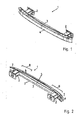
- FIG. 1 shows a motor vehicle bumper assembly 1 according to the invention, which has two crash boxes 2, a cross member 3 and a sheet metal part 4.
- FIG. 2 shows the same vehicle bumper assembly 1 in a perspective view from behind. It can be clearly seen that the cross member 3 has a straight course over its longitudinal axis 5. The cross member 3 is in each case coupled to the crash boxes 2 at the end.
- the sheet metal component 4 itself has a hat-shaped extending cross-section 6. At the ends 7, the sheet metal component 4 projects beyond the cross member 3 on the outside.
- the sheet metal component 4 overlaps the cross member 3 at least partially in each case a section 8, which is oriented near the ends 7 of the sheet metal component 4 and the end of the cross member 3 to the vehicle center 9 out.
- FIG. 3 shows the motor vehicle bumper assembly 1 according to the invention in a view from above.
- the straight course of the cross member 3 and an arcuate course along the longitudinal axis 10 of the sheet metal component 4 are formed with a distance A varying over the longitudinal direction relative to each other.
- two receiving openings 11 are shown on the cross member 3 in the region of the crash boxes 2, with which the sheet metal component 4 is coupled to the cross member 3.
- FIG. 4 shows a perspective view of the vehicle bumper assembly 1 without sheet metal part 4. It can be seen that the receiving opening 11 is also formed in the cross member 3.
- the respective end-side receiving opening 11a is according to FIG. 4 and better in FIG. 5 recognizable, designed as a slot 12, wherein the slot 12 is open at each end.
- FIG. 6 shows a motor vehicle bumper arrangement 1 according to the invention, wherein the sheet metal component 4 has two beads 14 at one end face 13.
- the beads 14 are arranged in the longitudinal direction 15 at the height of a connection region 16 of the crash boxes 2 such that they come at least partially flat at least in sections with the lying behind the sheet metal part 4 cross member 3 or with the crash boxes 2 at least partially.
- FIG. 7 shows a further embodiment, in which case the sheet metal part 4 is formed with a one-piece bead 14, which in turn in the connection region 16 at least partially flat to rest with the lying behind the sheet metal part 4 cross member 3 or with the crash boxes 2.
- FIG. 8 shows a sectional view taken along section line VII-VII of FIG. 7 ,
- the structure of the motor vehicle bumper arrangement 1 according to the invention is shown once again on the image plane from left to right.
- the connection to an unspecified motor vehicle is via a flange 17, followed by a crash box 2.
- a cross member 3 preferably coupled from simple extruded profile with straight course.
- a sheet metal component 4 is coupled, which has a one-piece bead 14 shown here over the substantial course in the longitudinal direction 15.
- the bead 14 comes in a contact area 18 at least partially with the cross member 3 to the plant.
Applications Claiming Priority (1)
| Application Number | Priority Date | Filing Date | Title |
|---|---|---|---|
| DE102011010174A DE102011010174A1 (de) | 2011-02-02 | 2011-02-02 | Stoßfängeranordnung |
Publications (2)
| Publication Number | Publication Date |
|---|---|
| EP2484561A1 true EP2484561A1 (fr) | 2012-08-08 |
| EP2484561B1 EP2484561B1 (fr) | 2013-11-20 |
Family
ID=45558525
Family Applications (1)
| Application Number | Title | Priority Date | Filing Date |
|---|---|---|---|
| EP12151494.7A Not-in-force EP2484561B1 (fr) | 2011-02-02 | 2012-01-18 | Agencement de pare-chocs |
Country Status (2)
| Country | Link |
|---|---|
| EP (1) | EP2484561B1 (fr) |
| DE (1) | DE102011010174A1 (fr) |
Cited By (1)
| Publication number | Priority date | Publication date | Assignee | Title |
|---|---|---|---|---|
| US10870403B2 (en) | 2017-12-06 | 2020-12-22 | Volkswagen Aktiengesellschaft | Bumper cross member system for a motor vehicle, modular system, and motor vehicle having such a bumper cross member system |
Families Citing this family (5)
| Publication number | Priority date | Publication date | Assignee | Title |
|---|---|---|---|---|
| DE102010012830B4 (de) * | 2010-03-25 | 2017-06-08 | Benteler Automobiltechnik Gmbh | Verfahren zur Herstellung einer Kraftfahrzeugkomponente und Karosseriebauteil |
| DE102014012081A1 (de) * | 2014-08-14 | 2015-09-24 | Daimler Ag | Biegequerträger |
| DE102014018421A1 (de) | 2014-12-11 | 2016-01-21 | Daimler Ag | Stoßfänger-Anordnung für ein Kraftfahrzeug sowie Stoßfänger |
| DE102016210880A1 (de) * | 2016-06-17 | 2017-12-21 | Bayerische Motoren Werke Aktiengesellschaft | Kraftfahrzeug |
| DE102016009392B4 (de) * | 2016-08-02 | 2020-01-09 | Daimler Ag | Kraftwagen mit einer Stoßfängeranordnung |
Citations (5)
| Publication number | Priority date | Publication date | Assignee | Title |
|---|---|---|---|---|
| DE19538844A1 (de) * | 1995-10-19 | 1997-04-24 | Ymos Ag Ind Produkte | Karosserie-Seitenteil für ein Kraftfahrzeug |
| DE19603958A1 (de) * | 1996-02-05 | 1997-08-07 | Ymos Ag Ind Produkte | Vorrichtung zur Befestigung eines Aufpralldämpfers, Längsträgers o. dgl. an dem Prallträger eines Fahrzeuges |
| DE19904879A1 (de) * | 1999-02-06 | 2000-08-17 | Porsche Ag | Stoßfänger für ein Fahrzeug |
| EP1595749A1 (fr) * | 2004-03-22 | 2005-11-16 | Peugeot Citroen Automobiles S.A. | Procédé de fabrication d'une platine de support d'un absorbeur d'énergie d'un pare-chocs et platine de support obtenue par un tel procédé |
| US20050285414A1 (en) * | 2004-06-25 | 2005-12-29 | F.Tech R&D North America Inc. | Vehicle bumper beam having non-uniform cross sections |
Family Cites Families (9)
| Publication number | Priority date | Publication date | Assignee | Title |
|---|---|---|---|---|
| US4961603A (en) * | 1989-12-19 | 1990-10-09 | Ford Motor Company | Vehicle bumper system |
| DE4019333C2 (de) * | 1990-06-18 | 1994-04-21 | Ford Werke Ag | Stoßfänger für Kraftfahrzeuge |
| JPH0939695A (ja) * | 1995-07-27 | 1997-02-10 | Nissan Motor Co Ltd | 車両用バンパ構造 |
| GB9825882D0 (en) * | 1998-11-27 | 1999-01-20 | Rover Group | A motor vehicle bumper mounting assembly |
| JP2002154869A (ja) * | 2000-11-09 | 2002-05-28 | Narita Seitoushiyo:Kk | トルマリン鉱石含有焼結体およびその製造方法 |
| US6764119B2 (en) * | 2002-01-22 | 2004-07-20 | Pullman Industries, Inc. | Vehicle bumper system |
| DE10226527A1 (de) * | 2002-06-14 | 2004-02-12 | Daimlerchrysler Ag | Stoßfängeranordnung für ein Kraftfahrzeug |
| DE10234045B4 (de) * | 2002-07-26 | 2004-09-09 | Audi Ag | Stossfängeranordnung an einem Kraftfahrzeug |
| DE202006016034U1 (de) * | 2006-10-16 | 2008-02-28 | Wagon Automotive Gmbh | Aufprallquerträger für eine Kraftfahrzeugkarosserie |
-
2011
- 2011-02-02 DE DE102011010174A patent/DE102011010174A1/de not_active Ceased
-
2012
- 2012-01-18 EP EP12151494.7A patent/EP2484561B1/fr not_active Not-in-force
Patent Citations (5)
| Publication number | Priority date | Publication date | Assignee | Title |
|---|---|---|---|---|
| DE19538844A1 (de) * | 1995-10-19 | 1997-04-24 | Ymos Ag Ind Produkte | Karosserie-Seitenteil für ein Kraftfahrzeug |
| DE19603958A1 (de) * | 1996-02-05 | 1997-08-07 | Ymos Ag Ind Produkte | Vorrichtung zur Befestigung eines Aufpralldämpfers, Längsträgers o. dgl. an dem Prallträger eines Fahrzeuges |
| DE19904879A1 (de) * | 1999-02-06 | 2000-08-17 | Porsche Ag | Stoßfänger für ein Fahrzeug |
| EP1595749A1 (fr) * | 2004-03-22 | 2005-11-16 | Peugeot Citroen Automobiles S.A. | Procédé de fabrication d'une platine de support d'un absorbeur d'énergie d'un pare-chocs et platine de support obtenue par un tel procédé |
| US20050285414A1 (en) * | 2004-06-25 | 2005-12-29 | F.Tech R&D North America Inc. | Vehicle bumper beam having non-uniform cross sections |
Cited By (1)
| Publication number | Priority date | Publication date | Assignee | Title |
|---|---|---|---|---|
| US10870403B2 (en) | 2017-12-06 | 2020-12-22 | Volkswagen Aktiengesellschaft | Bumper cross member system for a motor vehicle, modular system, and motor vehicle having such a bumper cross member system |
Also Published As
| Publication number | Publication date |
|---|---|
| DE102011010174A1 (de) | 2012-08-02 |
| EP2484561B1 (fr) | 2013-11-20 |
Similar Documents
| Publication | Publication Date | Title |
|---|---|---|
| EP2799314B1 (fr) | Structure de carrosserie, en particulier structure de plancher, de véhicule automobile | |
| EP1712451B1 (fr) | Châssis auxiliaire en forme d'un faux châssis pour véhicule automobile | |
| DE102013100720B4 (de) | Querträger für ein Kraftfahrzeug | |
| DE102011051481B4 (de) | Stoßfängeranordnung für ein Kraftfahrzeug | |
| EP2484561B1 (fr) | Agencement de pare-chocs | |
| WO2017067537A1 (fr) | Procédé de fabrication d'un composant automobile | |
| DE102015114105B4 (de) | Aufprallträger für ein Kraftfahrzeug sowie Verfahren zu seiner Herstellung | |
| DE102017124590A1 (de) | Einstückiger Doppelquerträger aus Extrusionsprofil | |
| DE4340033C2 (de) | Seitenaufprallträger | |
| DE102013001945A1 (de) | Schweller für eine Fahrzeugkarosserie | |
| WO2005118374A1 (fr) | Structure d'avant-corps de vehicule automobile comprenant un support integre d'essieu avant optimise en cas de collision | |
| DE102011012118A1 (de) | Hilfsrahmen für eine Karosserie eines Kraftwagens | |
| EP1880924B1 (fr) | Poutre en tant que traverse ou longeron dans un véhicule automobile | |
| DE102015105625A1 (de) | Stoßfängeranordnung für ein Kraftfahrzeug | |
| DE102013001668A1 (de) | Karosseriestruktur eines Kraftfahrzeugs und Kraftfahrzeug mit einer derartigen Karosseriestruktur | |
| EP3415349B1 (fr) | Dispositif de support pour une barre d'attelage et étrier de guidage dotés d'un élément de support multicomposant | |
| EP3427979B1 (fr) | Dispositif de support pour une barre d'attelage et étrier de guidage dotés d'un élément de support de forme étalon | |
| DE102013107179B4 (de) | Stoßabsorptionsvorrichtung für ein Kraftfahrzeug | |
| DE102012015246A1 (de) | Trägeranordnung für eine Anhängekupplung mit einem gehärteten Tragbauteil | |
| DE102018008894A1 (de) | Energieabsorptions-Baueinheit für einen Kraftwagen sowie Energieabsorptionselement und Verstärkungselement hierfür | |
| DE102019134712B4 (de) | Karosserieteilstruktur für ein wenigstens teilweise batteriebetriebenes Kraftfahrzeug | |
| DE102018120872B4 (de) | Deflektorschiene für Rahmenlängsträger | |
| DE102009047956A1 (de) | Säule für einen Kraftwagen | |
| DE102009031776A1 (de) | Kraftfahrzeugrahmenstruktur | |
| DE102016112344A1 (de) | Verstärkungsvorrichtung für eine Kraftfahrzeugtür |
Legal Events
| Date | Code | Title | Description |
|---|---|---|---|
| PUAI | Public reference made under article 153(3) epc to a published international application that has entered the european phase |
Free format text: ORIGINAL CODE: 0009012 |
|
| AK | Designated contracting states |
Kind code of ref document: A1 Designated state(s): AL AT BE BG CH CY CZ DE DK EE ES FI FR GB GR HR HU IE IS IT LI LT LU LV MC MK MT NL NO PL PT RO RS SE SI SK SM TR |
|
| AX | Request for extension of the european patent |
Extension state: BA ME |
|
| 17P | Request for examination filed |
Effective date: 20120905 |
|
| GRAP | Despatch of communication of intention to grant a patent |
Free format text: ORIGINAL CODE: EPIDOSNIGR1 |
|
| RIC1 | Information provided on ipc code assigned before grant |
Ipc: B60R 19/03 20060101AFI20130515BHEP |
|
| INTG | Intention to grant announced |
Effective date: 20130614 |
|
| GRAS | Grant fee paid |
Free format text: ORIGINAL CODE: EPIDOSNIGR3 |
|
| GRAP | Despatch of communication of intention to grant a patent |
Free format text: ORIGINAL CODE: EPIDOSNIGR1 |
|
| GRAA | (expected) grant |
Free format text: ORIGINAL CODE: 0009210 |
|
| INTG | Intention to grant announced |
Effective date: 20131008 |
|
| AK | Designated contracting states |
Kind code of ref document: B1 Designated state(s): AL AT BE BG CH CY CZ DE DK EE ES FI FR GB GR HR HU IE IS IT LI LT LU LV MC MK MT NL NO PL PT RO RS SE SI SK SM TR |
|
| REG | Reference to a national code |
Ref country code: GB Ref legal event code: FG4D Free format text: NOT ENGLISH |
|
| REG | Reference to a national code |
Ref country code: CH Ref legal event code: EP |
|
| REG | Reference to a national code |
Ref country code: AT Ref legal event code: REF Ref document number: 641390 Country of ref document: AT Kind code of ref document: T Effective date: 20131215 |
|
| REG | Reference to a national code |
Ref country code: IE Ref legal event code: FG4D Free format text: LANGUAGE OF EP DOCUMENT: GERMAN |
|
| REG | Reference to a national code |
Ref country code: DE Ref legal event code: R096 Ref document number: 502012000216 Country of ref document: DE Effective date: 20140116 |
|
| REG | Reference to a national code |
Ref country code: NL Ref legal event code: VDEP Effective date: 20131120 |
|
| REG | Reference to a national code |
Ref country code: LT Ref legal event code: MG4D |
|
| PG25 | Lapsed in a contracting state [announced via postgrant information from national office to epo] |
Ref country code: FI Free format text: LAPSE BECAUSE OF FAILURE TO SUBMIT A TRANSLATION OF THE DESCRIPTION OR TO PAY THE FEE WITHIN THE PRESCRIBED TIME-LIMIT Effective date: 20131120 Ref country code: HR Free format text: LAPSE BECAUSE OF FAILURE TO SUBMIT A TRANSLATION OF THE DESCRIPTION OR TO PAY THE FEE WITHIN THE PRESCRIBED TIME-LIMIT Effective date: 20131120 Ref country code: SE Free format text: LAPSE BECAUSE OF FAILURE TO SUBMIT A TRANSLATION OF THE DESCRIPTION OR TO PAY THE FEE WITHIN THE PRESCRIBED TIME-LIMIT Effective date: 20131120 Ref country code: LT Free format text: LAPSE BECAUSE OF FAILURE TO SUBMIT A TRANSLATION OF THE DESCRIPTION OR TO PAY THE FEE WITHIN THE PRESCRIBED TIME-LIMIT Effective date: 20131120 Ref country code: NO Free format text: LAPSE BECAUSE OF FAILURE TO SUBMIT A TRANSLATION OF THE DESCRIPTION OR TO PAY THE FEE WITHIN THE PRESCRIBED TIME-LIMIT Effective date: 20140220 Ref country code: NL Free format text: LAPSE BECAUSE OF FAILURE TO SUBMIT A TRANSLATION OF THE DESCRIPTION OR TO PAY THE FEE WITHIN THE PRESCRIBED TIME-LIMIT Effective date: 20131120 Ref country code: IS Free format text: LAPSE BECAUSE OF FAILURE TO SUBMIT A TRANSLATION OF THE DESCRIPTION OR TO PAY THE FEE WITHIN THE PRESCRIBED TIME-LIMIT Effective date: 20140320 |
|
| PG25 | Lapsed in a contracting state [announced via postgrant information from national office to epo] |
Ref country code: RS Free format text: LAPSE BECAUSE OF FAILURE TO SUBMIT A TRANSLATION OF THE DESCRIPTION OR TO PAY THE FEE WITHIN THE PRESCRIBED TIME-LIMIT Effective date: 20131120 Ref country code: LV Free format text: LAPSE BECAUSE OF FAILURE TO SUBMIT A TRANSLATION OF THE DESCRIPTION OR TO PAY THE FEE WITHIN THE PRESCRIBED TIME-LIMIT Effective date: 20131120 Ref country code: ES Free format text: LAPSE BECAUSE OF FAILURE TO SUBMIT A TRANSLATION OF THE DESCRIPTION OR TO PAY THE FEE WITHIN THE PRESCRIBED TIME-LIMIT Effective date: 20131120 |
|
| PG25 | Lapsed in a contracting state [announced via postgrant information from national office to epo] |
Ref country code: PT Free format text: LAPSE BECAUSE OF FAILURE TO SUBMIT A TRANSLATION OF THE DESCRIPTION OR TO PAY THE FEE WITHIN THE PRESCRIBED TIME-LIMIT Effective date: 20140320 |
|
| BERE | Be: lapsed |
Owner name: BENTELER AUTOMOBILTECHNIK G.M.B.H. Effective date: 20140131 |
|
| PG25 | Lapsed in a contracting state [announced via postgrant information from national office to epo] |
Ref country code: EE Free format text: LAPSE BECAUSE OF FAILURE TO SUBMIT A TRANSLATION OF THE DESCRIPTION OR TO PAY THE FEE WITHIN THE PRESCRIBED TIME-LIMIT Effective date: 20131120 |
|
| REG | Reference to a national code |
Ref country code: DE Ref legal event code: R097 Ref document number: 502012000216 Country of ref document: DE |
|
| PG25 | Lapsed in a contracting state [announced via postgrant information from national office to epo] |
Ref country code: RO Free format text: LAPSE BECAUSE OF FAILURE TO SUBMIT A TRANSLATION OF THE DESCRIPTION OR TO PAY THE FEE WITHIN THE PRESCRIBED TIME-LIMIT Effective date: 20131120 Ref country code: CZ Free format text: LAPSE BECAUSE OF FAILURE TO SUBMIT A TRANSLATION OF THE DESCRIPTION OR TO PAY THE FEE WITHIN THE PRESCRIBED TIME-LIMIT Effective date: 20131120 Ref country code: PL Free format text: LAPSE BECAUSE OF FAILURE TO SUBMIT A TRANSLATION OF THE DESCRIPTION OR TO PAY THE FEE WITHIN THE PRESCRIBED TIME-LIMIT Effective date: 20131120 Ref country code: LU Free format text: LAPSE BECAUSE OF FAILURE TO SUBMIT A TRANSLATION OF THE DESCRIPTION OR TO PAY THE FEE WITHIN THE PRESCRIBED TIME-LIMIT Effective date: 20140118 Ref country code: SK Free format text: LAPSE BECAUSE OF FAILURE TO SUBMIT A TRANSLATION OF THE DESCRIPTION OR TO PAY THE FEE WITHIN THE PRESCRIBED TIME-LIMIT Effective date: 20131120 |
|
| PLBE | No opposition filed within time limit |
Free format text: ORIGINAL CODE: 0009261 |
|
| STAA | Information on the status of an ep patent application or granted ep patent |
Free format text: STATUS: NO OPPOSITION FILED WITHIN TIME LIMIT |
|
| PG25 | Lapsed in a contracting state [announced via postgrant information from national office to epo] |
Ref country code: DK Free format text: LAPSE BECAUSE OF FAILURE TO SUBMIT A TRANSLATION OF THE DESCRIPTION OR TO PAY THE FEE WITHIN THE PRESCRIBED TIME-LIMIT Effective date: 20131120 |
|
| 26N | No opposition filed |
Effective date: 20140821 |
|
| REG | Reference to a national code |
Ref country code: FR Ref legal event code: ST Effective date: 20140930 |
|
| REG | Reference to a national code |
Ref country code: IE Ref legal event code: MM4A |
|
| PG25 | Lapsed in a contracting state [announced via postgrant information from national office to epo] |
Ref country code: FR Free format text: LAPSE BECAUSE OF NON-PAYMENT OF DUE FEES Effective date: 20140131 |
|
| REG | Reference to a national code |
Ref country code: DE Ref legal event code: R097 Ref document number: 502012000216 Country of ref document: DE Effective date: 20140821 |
|
| PG25 | Lapsed in a contracting state [announced via postgrant information from national office to epo] |
Ref country code: IE Free format text: LAPSE BECAUSE OF NON-PAYMENT OF DUE FEES Effective date: 20140118 |
|
| PG25 | Lapsed in a contracting state [announced via postgrant information from national office to epo] |
Ref country code: SI Free format text: LAPSE BECAUSE OF FAILURE TO SUBMIT A TRANSLATION OF THE DESCRIPTION OR TO PAY THE FEE WITHIN THE PRESCRIBED TIME-LIMIT Effective date: 20131120 |
|
| PG25 | Lapsed in a contracting state [announced via postgrant information from national office to epo] |
Ref country code: MC Free format text: LAPSE BECAUSE OF FAILURE TO SUBMIT A TRANSLATION OF THE DESCRIPTION OR TO PAY THE FEE WITHIN THE PRESCRIBED TIME-LIMIT Effective date: 20131120 |
|
| PG25 | Lapsed in a contracting state [announced via postgrant information from national office to epo] |
Ref country code: BE Free format text: LAPSE BECAUSE OF NON-PAYMENT OF DUE FEES Effective date: 20150131 |
|
| REG | Reference to a national code |
Ref country code: CH Ref legal event code: PL |
|
| PG25 | Lapsed in a contracting state [announced via postgrant information from national office to epo] |
Ref country code: LI Free format text: LAPSE BECAUSE OF NON-PAYMENT OF DUE FEES Effective date: 20150131 Ref country code: CH Free format text: LAPSE BECAUSE OF NON-PAYMENT OF DUE FEES Effective date: 20150131 |
|
| PG25 | Lapsed in a contracting state [announced via postgrant information from national office to epo] |
Ref country code: MT Free format text: LAPSE BECAUSE OF FAILURE TO SUBMIT A TRANSLATION OF THE DESCRIPTION OR TO PAY THE FEE WITHIN THE PRESCRIBED TIME-LIMIT Effective date: 20131120 |
|
| PG25 | Lapsed in a contracting state [announced via postgrant information from national office to epo] |
Ref country code: SM Free format text: LAPSE BECAUSE OF FAILURE TO SUBMIT A TRANSLATION OF THE DESCRIPTION OR TO PAY THE FEE WITHIN THE PRESCRIBED TIME-LIMIT Effective date: 20131120 |
|
| PG25 | Lapsed in a contracting state [announced via postgrant information from national office to epo] |
Ref country code: BG Free format text: LAPSE BECAUSE OF FAILURE TO SUBMIT A TRANSLATION OF THE DESCRIPTION OR TO PAY THE FEE WITHIN THE PRESCRIBED TIME-LIMIT Effective date: 20131120 Ref country code: IT Free format text: LAPSE BECAUSE OF FAILURE TO SUBMIT A TRANSLATION OF THE DESCRIPTION OR TO PAY THE FEE WITHIN THE PRESCRIBED TIME-LIMIT Effective date: 20131120 Ref country code: GR Free format text: LAPSE BECAUSE OF FAILURE TO SUBMIT A TRANSLATION OF THE DESCRIPTION OR TO PAY THE FEE WITHIN THE PRESCRIBED TIME-LIMIT Effective date: 20140221 Ref country code: CY Free format text: LAPSE BECAUSE OF FAILURE TO SUBMIT A TRANSLATION OF THE DESCRIPTION OR TO PAY THE FEE WITHIN THE PRESCRIBED TIME-LIMIT Effective date: 20131120 |
|
| PG25 | Lapsed in a contracting state [announced via postgrant information from national office to epo] |
Ref country code: HU Free format text: LAPSE BECAUSE OF FAILURE TO SUBMIT A TRANSLATION OF THE DESCRIPTION OR TO PAY THE FEE WITHIN THE PRESCRIBED TIME-LIMIT; INVALID AB INITIO Effective date: 20120118 Ref country code: TR Free format text: LAPSE BECAUSE OF FAILURE TO SUBMIT A TRANSLATION OF THE DESCRIPTION OR TO PAY THE FEE WITHIN THE PRESCRIBED TIME-LIMIT Effective date: 20131120 Ref country code: BE Free format text: LAPSE BECAUSE OF FAILURE TO SUBMIT A TRANSLATION OF THE DESCRIPTION OR TO PAY THE FEE WITHIN THE PRESCRIBED TIME-LIMIT Effective date: 20140131 |
|
| GBPC | Gb: european patent ceased through non-payment of renewal fee |
Effective date: 20160118 |
|
| PG25 | Lapsed in a contracting state [announced via postgrant information from national office to epo] |
Ref country code: GB Free format text: LAPSE BECAUSE OF NON-PAYMENT OF DUE FEES Effective date: 20160118 |
|
| PGFP | Annual fee paid to national office [announced via postgrant information from national office to epo] |
Ref country code: DE Payment date: 20170131 Year of fee payment: 6 |
|
| REG | Reference to a national code |
Ref country code: AT Ref legal event code: MM01 Ref document number: 641390 Country of ref document: AT Kind code of ref document: T Effective date: 20170118 |
|
| PG25 | Lapsed in a contracting state [announced via postgrant information from national office to epo] |
Ref country code: AT Free format text: LAPSE BECAUSE OF NON-PAYMENT OF DUE FEES Effective date: 20170118 |
|
| PG25 | Lapsed in a contracting state [announced via postgrant information from national office to epo] |
Ref country code: MK Free format text: LAPSE BECAUSE OF FAILURE TO SUBMIT A TRANSLATION OF THE DESCRIPTION OR TO PAY THE FEE WITHIN THE PRESCRIBED TIME-LIMIT Effective date: 20131120 |
|
| REG | Reference to a national code |
Ref country code: DE Ref legal event code: R119 Ref document number: 502012000216 Country of ref document: DE |
|
| PG25 | Lapsed in a contracting state [announced via postgrant information from national office to epo] |
Ref country code: DE Free format text: LAPSE BECAUSE OF NON-PAYMENT OF DUE FEES Effective date: 20180801 Ref country code: AL Free format text: LAPSE BECAUSE OF FAILURE TO SUBMIT A TRANSLATION OF THE DESCRIPTION OR TO PAY THE FEE WITHIN THE PRESCRIBED TIME-LIMIT Effective date: 20131120 |