EP2482010A2 - Expansionsventil - Google Patents
Expansionsventil Download PDFInfo
- Publication number
- EP2482010A2 EP2482010A2 EP20120150532 EP12150532A EP2482010A2 EP 2482010 A2 EP2482010 A2 EP 2482010A2 EP 20120150532 EP20120150532 EP 20120150532 EP 12150532 A EP12150532 A EP 12150532A EP 2482010 A2 EP2482010 A2 EP 2482010A2
- Authority
- EP
- European Patent Office
- Prior art keywords
- main body
- faces
- valve
- passage
- valve main
- Prior art date
- Legal status (The legal status is an assumption and is not a legal conclusion. Google has not performed a legal analysis and makes no representation as to the accuracy of the status listed.)
- Granted
Links
Images


Classifications
-
- F—MECHANICAL ENGINEERING; LIGHTING; HEATING; WEAPONS; BLASTING
- F25—REFRIGERATION OR COOLING; COMBINED HEATING AND REFRIGERATION SYSTEMS; HEAT PUMP SYSTEMS; MANUFACTURE OR STORAGE OF ICE; LIQUEFACTION SOLIDIFICATION OF GASES
- F25B—REFRIGERATION MACHINES, PLANTS OR SYSTEMS; COMBINED HEATING AND REFRIGERATION SYSTEMS; HEAT PUMP SYSTEMS
- F25B41/00—Fluid-circulation arrangements
- F25B41/30—Expansion means; Dispositions thereof
- F25B41/31—Expansion valves
- F25B41/33—Expansion valves with the valve member being actuated by the fluid pressure, e.g. by the pressure of the refrigerant
- F25B41/335—Expansion valves with the valve member being actuated by the fluid pressure, e.g. by the pressure of the refrigerant via diaphragms
-
- F—MECHANICAL ENGINEERING; LIGHTING; HEATING; WEAPONS; BLASTING
- F25—REFRIGERATION OR COOLING; COMBINED HEATING AND REFRIGERATION SYSTEMS; HEAT PUMP SYSTEMS; MANUFACTURE OR STORAGE OF ICE; LIQUEFACTION SOLIDIFICATION OF GASES
- F25B—REFRIGERATION MACHINES, PLANTS OR SYSTEMS; COMBINED HEATING AND REFRIGERATION SYSTEMS; HEAT PUMP SYSTEMS
- F25B2341/00—Details of ejectors not being used as compression device; Details of flow restrictors or expansion valves
- F25B2341/06—Details of flow restrictors or expansion valves
- F25B2341/068—Expansion valves combined with a sensor
- F25B2341/0683—Expansion valves combined with a sensor the sensor is disposed in the suction line and influenced by the temperature or the pressure of the suction gas
-
- F—MECHANICAL ENGINEERING; LIGHTING; HEATING; WEAPONS; BLASTING
- F25—REFRIGERATION OR COOLING; COMBINED HEATING AND REFRIGERATION SYSTEMS; HEAT PUMP SYSTEMS; MANUFACTURE OR STORAGE OF ICE; LIQUEFACTION SOLIDIFICATION OF GASES
- F25B—REFRIGERATION MACHINES, PLANTS OR SYSTEMS; COMBINED HEATING AND REFRIGERATION SYSTEMS; HEAT PUMP SYSTEMS
- F25B2500/00—Problems to be solved
- F25B2500/32—Weight
-
- Y—GENERAL TAGGING OF NEW TECHNOLOGICAL DEVELOPMENTS; GENERAL TAGGING OF CROSS-SECTIONAL TECHNOLOGIES SPANNING OVER SEVERAL SECTIONS OF THE IPC; TECHNICAL SUBJECTS COVERED BY FORMER USPC CROSS-REFERENCE ART COLLECTIONS [XRACs] AND DIGESTS
- Y10—TECHNICAL SUBJECTS COVERED BY FORMER USPC
- Y10T—TECHNICAL SUBJECTS COVERED BY FORMER US CLASSIFICATION
- Y10T137/00—Fluid handling
- Y10T137/7722—Line condition change responsive valves
- Y10T137/7737—Thermal responsive
Definitions
- the present invention relates to an expansion valve used in a refrigerant cycle.
- a valve main body of an expansion valve used in a refrigerant cycle for a vehicle air conditioner or the like is produced by machining a material which is obtained by an extrusion molding of a metal material such an aluminum alloy or the like.
- Japanese Patent Application Laid-Open No. 2002-206134 discloses an expansion valve having such a kind of the valve main body.
- valve main body of the expansion valve uses a material proper for an extrusion molding, such as an aluminum alloy or the like, the valve main body is appropriate for requirement for weight saving in light of its material. However, further weight saving has been required due to requirements for saving energy of the air conditioner, reducing load to an environment, and the like.
- a long material is produced by an extrusion molding of an aluminum alloy or the like at first, and then the long material is cut to obtain a material to be machined.
- the obtained material is a roughly hexahedral prismatic. Four faces of the prismatic are machined, and the remaining two faces are used as a face for chucking at a time of machining.
- the present invention focuses on the structure of the aforementioned valve main body, and has an objective to provide an expansion valve enabling to realize further weight saving.
- the expansion valve includes a valve main body, a valve body, and a power element.
- the valve main body has a first passage, in which a high-pressure refrigerant passes from a condenser to an evaporator, an orifice provided at a middle of the first passage and for reducing pressure of the high-pressure refrigerant, and a second passage, in which a low -pressure refrigerant passes from the evaporator to the condenser.
- the valve body performs opening/closing of the orifice.
- the power element drives the valve body based on a temperature and a pressure on the outlet side of the evaporator.
- the valve main body is formed by the extrusion molding.
- both side faces in the extruding direction of the valve main body are held in the orthogonal direction to the extruding direction by a chuck mechanism, a face intersecting the both side faces is machined, so that the first passage, the second passage, the orifice and attaching hole of the power element are formed.
- the both side faces have a pair of holding faces held by the chuck mechanism.
- portions other than the holding faces are formed to have concave parts which are concave more on the inner side than the holding faces, and the holding faces and the concave parts are formed at a time of the extrusion molding.
- the concave parts along a peripheral face of the second passage are formed on both sides in the axial direction of the second passage, and the pair of the holding faces is formed on the upper and lower sides of the concave part.
- the concave parts along a peripheral face of the first passage are formed on both sides in the axial direction of the first passage, and the pair of the holding faces is formed on the upper and lower sides of the concave part.
- the two portions on the both side faces in the extrusion direction are remained as holding faces for holding by the chuck mechanism at a time of machining, and the other faces on the both side faces are extruded to have concave shapes by removing the upper portion of the other faces.
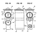
- the expansion valve of the present exemplary embodiment includes a valve main body 100 made of an aluminum alloy, and a power element 40 fixed on an upper face 100e of the valve main body 100.
- the valve main body 100 has two side faces 100a and 100b, a front face 100c, a back face 100d, an upper face 100e, and a lower face 100f, which are formed by an extrusion mold, when the aluminum alloy is cold-extruded.
- the front face 100c, the back face 100d, the upper face 100e, and lower face 100f are orthogonal to the two side faces 100a and 100b,
- an inlet passage 110 for introducing a high-pressure liquid refrigerant transmitted from the condenser side is formed near a lower end of the back face 100d of the valve main body 100.
- a small diameter hole 112 is provided at a depth wall and is communicated with a valve chamber 120.
- the valve chamber 120 is a round hole in the shape of a multistage column, which is machined from the lower face 100f side of the valve main body 100, and a screw 122 to which a plug 16 is screwed is formed at an inner peripheral part of a lower end opening of the valve chamber 120.
- a ball-shaped valve body 10 is disposed, and the valve body 10 is supported by the plug 16 via a supporting member 12 and a coil spring 14.
- An annular seal member 20 is fitted to an upper end outer peripheral part of the plug 16.
- An orifice 130 is provided at an upper part of the valve chamber 120, and a valve seat 124 with/from which the valve body 10 is brought into contact/separated is formed at a lower end of the valve chamber 120.
- valve rod 30 A lower end part of a valve rod 30 is in contact with the valve body 10.
- outlet passages 140 and 142 for refrigerant are formed in parallel with an inlet passage 110 for refrigerant.
- the outlet passages 140 and 142 are formed by machining from the front face 100c side of the valve main body 100.
- the inlet passage 110 and the outlet passages 140 and 142 are communicated by the orifice 130.
- the valve rod 30 is inserted, and the valve rod 30 is guided by a guide hole 132 formed on the valve main body 100 to slide.
- a vibration-proof member 32 is mounted to a hole 134 formed coaxially with the guide hole 132 and prevents vibrations of the valve rod 30 and the valve body 10.
- the refrigerant sent from the outlet passage 142 to the evaporator side performs heat exchange with the open air in the evaporator, and returns to the condenser side. At this time, the refrigerant passes through a return passage 150 formed in the valve main body 100.
- the return passage 150 is a pillar hole penetrating from the front face 100c to the back face 100d of the valve main body 100.
- the valve rod 30 penetrates the return passage 150 in the diameter direction and projects toward the upper face 100e side of the valve main body 100.
- a screw hole 160 for fixing the power element 40 is formed on the upper face 100e side of the valve main body 100.
- the inside is divided into upper and lower chambers by a diaphragm 42, and the upper chamber is a gas chamber 44 for enclosing a heatsensitive gas for driving a diaphragm.
- a stopper member 50 is disposed on a lower face of the diaphragm 42. The stopper member 50 transmits displacement of the diaphragm 42 to the valve rod 30 and drives the valve body 10.
- the screw hole 160 communicates with the return passage 150 via an opening 136, and the temperature and the pressure of the refrigerant passing through the return passage 150 are transmitted to the lower face of the diaphragm 42.
- An annular seal member 60 is disposed between the upper face 100e of the valve main body 100 and the power element 40.
- one bottomed screw hole 170 is formed.
- two attaching holes 180 penetrating from the front face 100c to the back face 100d of the valve main body 100 are formed.
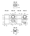
- valve main body 100 of the present exemplary embodiment two flat holding faces 101 a and 101 b, which form the outer most face among faces forming the left side face 100a of the valve main body 100 are remained, and other faces are shaped to be concave more on the inner side than the holding faces 101 a and 101 b.
- the concave part 101c between the holding faces 101 a and 101 b is formed to have a waved cross section so as to be as thin as possible along the inner peripheral face of the return passage 150.
- the concave part 101 d more on the lower side than the holding face 101 b is formed to have a waved cross section so as to be as thin as possible along the inner peripheral faces of the outlet passage 142 and the inlet passage 110.
- the holding face 101 a is formed between the return passage 150 and the upper face 100e of the valve main body 100 to which the power element 40 is mounted.
- the holding face 101 b is formed at a near center part between the upper face 100e and the lower face 100f of the valve main body 100.
- the two holding faces 101 a and 101 b are formed to have a width dimension proper for holding by a chuck claw when machining the valve main body 100.
- two holding faces 102a and 102b, and thin concave parts 102c and 102d are formed on the right side face 100b of the valve main body 100. These holding faces 102a and 102b and the concave parts 102c and 102d are formed symmetrically to the left side.
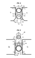
- Fig. 4 illustrates a state that the front face 100c and the upper face 100e of the valve main body 100 are machined while holding the valve main body 100 with chuck claws C 1 and C 2 of a machine tool.
- the chuck claws C 1 and C 2 hold the left side face 100a and the right side face 100b of the valve main body 100 in the direction orthogonal to the extruding direction.
- the holding faces 101 a and 101 b are formed on the left side face 100a
- the holding faces 102a and 102b are formed on the right side face 100b.
- the holding faces 101 a and 102a are mutually parallel
- the holding faces 101b and 102b are mutually parallel.
- the chuck claws C 1 and C 2 can certainly hold the valve main body 100.
- the outlet passages 140 and 142 and the return passage 150 are machined from the front face 100c side to the back face 100d side of the valve main body 100. Further, the screw hole 160 for attaching the power element 40, and the guide hole 132 of the valve rod 30 are machined from the upper face 100e side.
- the chuck claws C 1 and C 2 applies appropriate pressures P 1 and P 2 to the holding faces 101 a and 102a and the holding faces 101b and 102b, which are opposed each other, so that these faces can certainly receive stress generating at the valve main body 100 when machining.
- the width dimensions of the holding faces 101 a and 102a and the holding faces 101 b and 102b are set to be appropriate dimensions, which do not generate unnecessary stress and can apply necessary friction force to hold the valve main body 100, when the pressure P 1 and P 2 are applied.
- Fig. 5 illustrates a state of reversing the valve main body 100 up and down and holding it.
- the valve main body 100 is machined from the back face 100d side thereof.
- the parts to be machined are the inlet passage 110 for refrigerant, the small diameter hole 112, the return passage 150, the bottomed screw hole 170, and the penetration hole 180 in which a bolt for attachment is inserted.
- the valve chamber 120, the orifice 130 are machined from the lower face 1 00f side.
- a cross-sectional shape of the present exemplary embodiment is the same as that in Fig. 2 .
- a valve main body in which the entirety is noted by the code number 200 has a hexahedral structure including a left side face 200a, a right side face 200b, a front face 200c, a back face 200d, an upper face 200e, and a lower face 200f.
- a small diameter hole 212 communicating with an inlet passage 210 of refrigerant and a valve chamber 220 is provided on the lower end side of the back face 200d of the valve main body 200.
- Outlet passages 240 and 242 for discharging refrigerant toward the evaporator side are provided at the front face 200c of the valve main body 200.
- a screw hole 260 for attaching a power element, a guide hole 232 of a valve rod provided coaxially with the screw hole 260 are machined.
- a material of the valve main body 200 is produced by a cold-extrusion molding of an aluminum alloy in the direction orthogonal to the front face 200c and the back face 200d. It is not necessary to machine the both side faces 200a and 200b of the valve main body 200.
- holding faces 201a and 202a are formed at a nearly center part in the upper and lower directions of the both side faces 200a and 200b, and holding faces 201 b and 202b are formed at lower end parts.
- the other portions of the both side faces 200a and 200b are formed in a concave shape, which is concave more on the inner side than the holding faces 201 a and 202a and the holding faces 201 b and 202b.
- Fig. 7 illustrates a state that the valve main body 200 is chucked by a machine tool.
- Chuck claws C 1 and C 2 hold the two pair of holding faces 201 a and 202a, and 201 b and 202b of the valve main body 200, which are opposed each other.
- the inlet passages 210 and 212 for refrigerant, the return passage 250 for refrigerant, the bottomed screw hole 270, the two through holes 280 for the attaching bolts, and the like are machined from the back face 200d side of the valve main body 200.
- portions necessary for machining such as the screw hole 260 for attaching the power element, the guide hole 232 of the valve rod, and the like are machined.
- Fig. 8 illustrates a state that the valve main body 200 is rotated up and down and held by the chuck claws C 1 and C 2 .
- portions necessary for machining such as the outlet passages 240, 242 and the like are machined from the front face 200c side of the valve main body.
- a valve chamber 220 and a screw hole 222 for screwing a plug for sealing the valve chamber 220 are machined from the lower face 200f side.
- the expansion valve of the present invention can attain to reduce in the weight as lower as possible.
- an expansion valve having a structure that a plug for sealing a valve chamber is mounted to a lower face of the valve main body is described as an example.
- the present invention can be applied to a un-adjustment type expansion valve not including a plug.
Landscapes
- Physics & Mathematics (AREA)
- Engineering & Computer Science (AREA)
- Fluid Mechanics (AREA)
- Mechanical Engineering (AREA)
- Thermal Sciences (AREA)
- General Engineering & Computer Science (AREA)
- Valve Housings (AREA)
- Temperature-Responsive Valves (AREA)
Applications Claiming Priority (1)
| Application Number | Priority Date | Filing Date | Title |
|---|---|---|---|
| JP2011017967A JP6078219B2 (ja) | 2011-01-31 | 2011-01-31 | 膨張弁 |
Publications (3)
| Publication Number | Publication Date |
|---|---|
| EP2482010A2 true EP2482010A2 (de) | 2012-08-01 |
| EP2482010A3 EP2482010A3 (de) | 2014-03-12 |
| EP2482010B1 EP2482010B1 (de) | 2020-01-22 |
Family
ID=45445946
Family Applications (1)
| Application Number | Title | Priority Date | Filing Date |
|---|---|---|---|
| EP12150532.5A Active EP2482010B1 (de) | 2011-01-31 | 2012-01-10 | Expansionsventil |
Country Status (4)
| Country | Link |
|---|---|
| US (1) | US8667984B2 (de) |
| EP (1) | EP2482010B1 (de) |
| JP (1) | JP6078219B2 (de) |
| CN (1) | CN102620492B (de) |
Families Citing this family (15)
| Publication number | Priority date | Publication date | Assignee | Title |
|---|---|---|---|---|
| USD683820S1 (en) | 2011-02-28 | 2013-06-04 | Tgk Co., Ltd. | Expansion valve of an air conditioning system |
| USD683819S1 (en) | 2011-02-28 | 2013-06-04 | Tgk Co., Ltd. | Expansion valve of an air conditioning system |
| JP6064114B2 (ja) * | 2012-03-22 | 2017-01-25 | 株式会社テージーケー | 膨張弁 |
| USD722135S1 (en) * | 2013-07-23 | 2015-02-03 | Tgk Co., Ltd. | Expansion valve |
| CN105485982B (zh) * | 2015-12-30 | 2018-04-06 | 浙江新劲空调设备有限公司 | 减振降噪膨胀阀 |
| USD799640S1 (en) * | 2016-04-01 | 2017-10-10 | Tgk Co., Ltd. | Expansion valve |
| JP1571364S (de) * | 2016-04-01 | 2017-03-13 | ||
| USD799009S1 (en) * | 2016-09-29 | 2017-10-03 | Tgk Co., Ltd. | Expansion valve |
| JP1588870S (de) * | 2016-11-01 | 2017-10-23 | ||
| JP1588871S (de) * | 2016-11-01 | 2017-10-23 | ||
| JP1588868S (de) * | 2016-11-01 | 2017-10-23 | ||
| JP1588869S (de) * | 2016-11-01 | 2017-10-23 | ||
| CN110397758B (zh) * | 2018-04-24 | 2022-03-08 | 盾安汽车热管理科技有限公司 | 一种膨胀阀及补气增焓系统 |
| USD886237S1 (en) | 2018-09-04 | 2020-06-02 | Swagelok Company | Thermal trace valve body |
| CN111720559B (zh) * | 2019-03-20 | 2022-09-23 | 浙江三花汽车零部件有限公司 | 控制阀及空调系统 |
Citations (1)
| Publication number | Priority date | Publication date | Assignee | Title |
|---|---|---|---|---|
| JP2002206134A (ja) | 2000-10-03 | 2002-07-26 | Kobe Steel Ltd | 耐粒界腐食性に優れるアルミニウム合金押出材並びにそれを用いた冷凍サイクルを構成する機器及び温度式膨張弁 |
Family Cites Families (18)
| Publication number | Priority date | Publication date | Assignee | Title |
|---|---|---|---|---|
| US3810366A (en) * | 1972-07-31 | 1974-05-14 | Controls Co Of America | Refrigeration valve |
| JP3545847B2 (ja) * | 1995-07-12 | 2004-07-21 | 株式会社不二工機 | 膨張弁 |
| FR2757613B1 (fr) * | 1996-12-23 | 1999-03-05 | Valeo Climatisation | Dispositif de raccordement de tubulures a un bloc detendeur d'un circuit de climatisation, en particulier de vehicule automobile |
| JP4014688B2 (ja) * | 1997-03-27 | 2007-11-28 | 株式会社不二工機 | 膨張弁 |
| JPH11223425A (ja) * | 1998-02-10 | 1999-08-17 | Fujikoki Corp | 膨張弁 |
| JPH11325660A (ja) * | 1998-03-18 | 1999-11-26 | Fujikoki Corp | 膨張弁 |
| USD429315S (en) * | 1998-07-29 | 2000-08-08 | Pacific Industrial Co., Ltd. | Thermal type expansion valve |
| JP4294155B2 (ja) * | 1999-04-16 | 2009-07-08 | 株式会社不二工機 | 温度膨張弁 |
| JP2000346494A (ja) * | 1999-06-10 | 2000-12-15 | Fuji Koki Corp | 温度式膨張弁 |
| JP4156212B2 (ja) * | 2001-05-29 | 2008-09-24 | 株式会社不二工機 | 膨張弁 |
| JP2004053182A (ja) * | 2002-07-23 | 2004-02-19 | Fuji Koki Corp | 膨張弁 |
| EP1666817A3 (de) * | 2004-12-01 | 2007-01-17 | Fujikoki Corporation | Druckregelventil |
| JP2007183082A (ja) * | 2005-03-04 | 2007-07-19 | Tgk Co Ltd | 膨張弁 |
| CN101135384A (zh) * | 2006-08-29 | 2008-03-05 | 浙江春晖智能控制股份有限公司 | 带过滤结构的二次节流h型汽车空调热力膨胀阀 |
| JP5100136B2 (ja) * | 2007-01-26 | 2012-12-19 | 株式会社不二工機 | 膨張弁 |
| TWD136608S1 (zh) * | 2007-09-27 | 2010-08-21 | 不二工機股份有限公司 | 膨脹閥 |
| EP2206995B1 (de) * | 2007-10-24 | 2013-03-06 | Fujikoki Corporation | Expansionsventil |
| USD647597S1 (en) * | 2010-12-07 | 2011-10-25 | Fujikoki Corporation | Expansion valve |
-
2011
- 2011-01-31 JP JP2011017967A patent/JP6078219B2/ja active Active
- 2011-12-08 CN CN201110406997.7A patent/CN102620492B/zh active Active
-
2012
- 2012-01-05 US US13/343,987 patent/US8667984B2/en active Active
- 2012-01-10 EP EP12150532.5A patent/EP2482010B1/de active Active
Patent Citations (1)
| Publication number | Priority date | Publication date | Assignee | Title |
|---|---|---|---|---|
| JP2002206134A (ja) | 2000-10-03 | 2002-07-26 | Kobe Steel Ltd | 耐粒界腐食性に優れるアルミニウム合金押出材並びにそれを用いた冷凍サイクルを構成する機器及び温度式膨張弁 |
Also Published As
| Publication number | Publication date |
|---|---|
| US8667984B2 (en) | 2014-03-11 |
| US20120192970A1 (en) | 2012-08-02 |
| CN102620492A (zh) | 2012-08-01 |
| EP2482010A3 (de) | 2014-03-12 |
| JP2012159119A (ja) | 2012-08-23 |
| EP2482010B1 (de) | 2020-01-22 |
| CN102620492B (zh) | 2016-07-13 |
| JP6078219B2 (ja) | 2017-02-08 |
Similar Documents
| Publication | Publication Date | Title |
|---|---|---|
| EP2482010B1 (de) | Expansionsventil | |
| US9169888B2 (en) | Tube provided with branch tube, shock absorber, and method for making them | |
| JP6064114B2 (ja) | 膨張弁 | |
| US6530149B2 (en) | Method for producing hollow piston for compressor by forging | |
| JP6103384B2 (ja) | 流体圧シリンダに用いられるピストンの連結構造及びその連結方法 | |
| US20180180070A1 (en) | Valve body for hydraulic control device, and production method therefor | |
| EP3076104B1 (de) | Leistungselement vom dichtfixierungstyp und expansionsventil damit | |
| CN107690530B (zh) | 流体压力缸 | |
| KR20160039538A (ko) | 제어 밸브 | |
| TWI577893B (zh) | 流體壓力缸 | |
| JP2007183082A (ja) | 膨張弁 | |
| JP6435486B2 (ja) | 制御弁 | |
| KR20110110723A (ko) | 유체압 기기에 사용되는 캡 및 그 고정 방법 | |
| JP6379959B2 (ja) | 冷凍サイクル用圧縮機 | |
| US20180172146A1 (en) | Valve body for hydraulic control device, and production method therefor | |
| EP1416235B1 (de) | Expansionsventil mit einem Magnetventil | |
| KR101152218B1 (ko) | 리니어 액츄에이터 | |
| US20170009882A1 (en) | Piston device, method for the production of such a piston device and piston cylinder unit comprising such a piston device | |
| JP2006300508A (ja) | 電磁弁一体型膨張弁 | |
| KR102148655B1 (ko) | 차량 브레이크 시스템용 피스톤 펌프의 피스톤 | |
| JP7378343B2 (ja) | ピストンロッドアセンブリ、緩衝器およびピストンロッドアセンブリの製造方法 | |
| CN109989994A (zh) | 电磁切换阀及其连杆 | |
| AU2014101402A4 (en) | A method of fabricating an ejector for a solar energy system | |
| JP6327774B2 (ja) | マスタシリンダ | |
| JP2005226941A (ja) | 膨張弁 |
Legal Events
| Date | Code | Title | Description |
|---|---|---|---|
| PUAI | Public reference made under article 153(3) epc to a published international application that has entered the european phase |
Free format text: ORIGINAL CODE: 0009012 |
|
| AK | Designated contracting states |
Kind code of ref document: A2 Designated state(s): AL AT BE BG CH CY CZ DE DK EE ES FI FR GB GR HR HU IE IS IT LI LT LU LV MC MK MT NL NO PL PT RO RS SE SI SK SM TR |
|
| AX | Request for extension of the european patent |
Extension state: BA ME |
|
| PUAL | Search report despatched |
Free format text: ORIGINAL CODE: 0009013 |
|
| AK | Designated contracting states |
Kind code of ref document: A3 Designated state(s): AL AT BE BG CH CY CZ DE DK EE ES FI FR GB GR HR HU IE IS IT LI LT LU LV MC MK MT NL NO PL PT RO RS SE SI SK SM TR |
|
| AX | Request for extension of the european patent |
Extension state: BA ME |
|
| RIC1 | Information provided on ipc code assigned before grant |
Ipc: F25B 41/06 20060101AFI20140131BHEP |
|
| 17P | Request for examination filed |
Effective date: 20140815 |
|
| RBV | Designated contracting states (corrected) |
Designated state(s): AL AT BE BG CH CY CZ DE DK EE ES FI FR GB GR HR HU IE IS IT LI LT LU LV MC MK MT NL NO PL PT RO RS SE SI SK SM TR |
|
| STAA | Information on the status of an ep patent application or granted ep patent |
Free format text: STATUS: EXAMINATION IS IN PROGRESS |
|
| 17Q | First examination report despatched |
Effective date: 20170306 |
|
| GRAP | Despatch of communication of intention to grant a patent |
Free format text: ORIGINAL CODE: EPIDOSNIGR1 |
|
| STAA | Information on the status of an ep patent application or granted ep patent |
Free format text: STATUS: GRANT OF PATENT IS INTENDED |
|
| INTG | Intention to grant announced |
Effective date: 20190423 |
|
| GRAJ | Information related to disapproval of communication of intention to grant by the applicant or resumption of examination proceedings by the epo deleted |
Free format text: ORIGINAL CODE: EPIDOSDIGR1 |
|
| STAA | Information on the status of an ep patent application or granted ep patent |
Free format text: STATUS: EXAMINATION IS IN PROGRESS |
|
| GRAP | Despatch of communication of intention to grant a patent |
Free format text: ORIGINAL CODE: EPIDOSNIGR1 |
|
| INTC | Intention to grant announced (deleted) | ||
| STAA | Information on the status of an ep patent application or granted ep patent |
Free format text: STATUS: GRANT OF PATENT IS INTENDED |
|
| INTG | Intention to grant announced |
Effective date: 20190919 |
|
| GRAS | Grant fee paid |
Free format text: ORIGINAL CODE: EPIDOSNIGR3 |
|
| GRAA | (expected) grant |
Free format text: ORIGINAL CODE: 0009210 |
|
| STAA | Information on the status of an ep patent application or granted ep patent |
Free format text: STATUS: THE PATENT HAS BEEN GRANTED |
|
| AK | Designated contracting states |
Kind code of ref document: B1 Designated state(s): AL AT BE BG CH CY CZ DE DK EE ES FI FR GB GR HR HU IE IS IT LI LT LU LV MC MK MT NL NO PL PT RO RS SE SI SK SM TR |
|
| REG | Reference to a national code |
Ref country code: GB Ref legal event code: FG4D |
|
| REG | Reference to a national code |
Ref country code: CH Ref legal event code: EP |
|
| REG | Reference to a national code |
Ref country code: DE Ref legal event code: R096 Ref document number: 602012067354 Country of ref document: DE |
|
| REG | Reference to a national code |
Ref country code: AT Ref legal event code: REF Ref document number: 1227159 Country of ref document: AT Kind code of ref document: T Effective date: 20200215 |
|
| REG | Reference to a national code |
Ref country code: IE Ref legal event code: FG4D |
|
| REG | Reference to a national code |
Ref country code: NL Ref legal event code: MP Effective date: 20200122 |
|
| REG | Reference to a national code |
Ref country code: LT Ref legal event code: MG4D |
|
| PG25 | Lapsed in a contracting state [announced via postgrant information from national office to epo] |
Ref country code: NL Free format text: LAPSE BECAUSE OF FAILURE TO SUBMIT A TRANSLATION OF THE DESCRIPTION OR TO PAY THE FEE WITHIN THE PRESCRIBED TIME-LIMIT Effective date: 20200122 Ref country code: NO Free format text: LAPSE BECAUSE OF FAILURE TO SUBMIT A TRANSLATION OF THE DESCRIPTION OR TO PAY THE FEE WITHIN THE PRESCRIBED TIME-LIMIT Effective date: 20200422 Ref country code: FI Free format text: LAPSE BECAUSE OF FAILURE TO SUBMIT A TRANSLATION OF THE DESCRIPTION OR TO PAY THE FEE WITHIN THE PRESCRIBED TIME-LIMIT Effective date: 20200122 Ref country code: PT Free format text: LAPSE BECAUSE OF FAILURE TO SUBMIT A TRANSLATION OF THE DESCRIPTION OR TO PAY THE FEE WITHIN THE PRESCRIBED TIME-LIMIT Effective date: 20200614 Ref country code: RS Free format text: LAPSE BECAUSE OF FAILURE TO SUBMIT A TRANSLATION OF THE DESCRIPTION OR TO PAY THE FEE WITHIN THE PRESCRIBED TIME-LIMIT Effective date: 20200122 |
|
| PG25 | Lapsed in a contracting state [announced via postgrant information from national office to epo] |
Ref country code: HR Free format text: LAPSE BECAUSE OF FAILURE TO SUBMIT A TRANSLATION OF THE DESCRIPTION OR TO PAY THE FEE WITHIN THE PRESCRIBED TIME-LIMIT Effective date: 20200122 Ref country code: GR Free format text: LAPSE BECAUSE OF FAILURE TO SUBMIT A TRANSLATION OF THE DESCRIPTION OR TO PAY THE FEE WITHIN THE PRESCRIBED TIME-LIMIT Effective date: 20200423 Ref country code: IS Free format text: LAPSE BECAUSE OF FAILURE TO SUBMIT A TRANSLATION OF THE DESCRIPTION OR TO PAY THE FEE WITHIN THE PRESCRIBED TIME-LIMIT Effective date: 20200522 Ref country code: BG Free format text: LAPSE BECAUSE OF FAILURE TO SUBMIT A TRANSLATION OF THE DESCRIPTION OR TO PAY THE FEE WITHIN THE PRESCRIBED TIME-LIMIT Effective date: 20200422 Ref country code: SE Free format text: LAPSE BECAUSE OF FAILURE TO SUBMIT A TRANSLATION OF THE DESCRIPTION OR TO PAY THE FEE WITHIN THE PRESCRIBED TIME-LIMIT Effective date: 20200122 Ref country code: LV Free format text: LAPSE BECAUSE OF FAILURE TO SUBMIT A TRANSLATION OF THE DESCRIPTION OR TO PAY THE FEE WITHIN THE PRESCRIBED TIME-LIMIT Effective date: 20200122 |
|
| REG | Reference to a national code |
Ref country code: DE Ref legal event code: R097 Ref document number: 602012067354 Country of ref document: DE |
|
| PG25 | Lapsed in a contracting state [announced via postgrant information from national office to epo] |
Ref country code: EE Free format text: LAPSE BECAUSE OF FAILURE TO SUBMIT A TRANSLATION OF THE DESCRIPTION OR TO PAY THE FEE WITHIN THE PRESCRIBED TIME-LIMIT Effective date: 20200122 Ref country code: SM Free format text: LAPSE BECAUSE OF FAILURE TO SUBMIT A TRANSLATION OF THE DESCRIPTION OR TO PAY THE FEE WITHIN THE PRESCRIBED TIME-LIMIT Effective date: 20200122 Ref country code: CZ Free format text: LAPSE BECAUSE OF FAILURE TO SUBMIT A TRANSLATION OF THE DESCRIPTION OR TO PAY THE FEE WITHIN THE PRESCRIBED TIME-LIMIT Effective date: 20200122 Ref country code: RO Free format text: LAPSE BECAUSE OF FAILURE TO SUBMIT A TRANSLATION OF THE DESCRIPTION OR TO PAY THE FEE WITHIN THE PRESCRIBED TIME-LIMIT Effective date: 20200122 Ref country code: SK Free format text: LAPSE BECAUSE OF FAILURE TO SUBMIT A TRANSLATION OF THE DESCRIPTION OR TO PAY THE FEE WITHIN THE PRESCRIBED TIME-LIMIT Effective date: 20200122 Ref country code: ES Free format text: LAPSE BECAUSE OF FAILURE TO SUBMIT A TRANSLATION OF THE DESCRIPTION OR TO PAY THE FEE WITHIN THE PRESCRIBED TIME-LIMIT Effective date: 20200122 Ref country code: DK Free format text: LAPSE BECAUSE OF FAILURE TO SUBMIT A TRANSLATION OF THE DESCRIPTION OR TO PAY THE FEE WITHIN THE PRESCRIBED TIME-LIMIT Effective date: 20200122 Ref country code: LT Free format text: LAPSE BECAUSE OF FAILURE TO SUBMIT A TRANSLATION OF THE DESCRIPTION OR TO PAY THE FEE WITHIN THE PRESCRIBED TIME-LIMIT Effective date: 20200122 |
|
| REG | Reference to a national code |
Ref country code: AT Ref legal event code: MK05 Ref document number: 1227159 Country of ref document: AT Kind code of ref document: T Effective date: 20200122 |
|
| PLBE | No opposition filed within time limit |
Free format text: ORIGINAL CODE: 0009261 |
|
| REG | Reference to a national code |
Ref country code: DE Ref legal event code: R079 Ref document number: 602012067354 Country of ref document: DE Free format text: PREVIOUS MAIN CLASS: F25B0041060000 Ipc: F25B0041300000 |
|
| STAA | Information on the status of an ep patent application or granted ep patent |
Free format text: STATUS: NO OPPOSITION FILED WITHIN TIME LIMIT |
|
| 26N | No opposition filed |
Effective date: 20201023 |
|
| PG25 | Lapsed in a contracting state [announced via postgrant information from national office to epo] |
Ref country code: AT Free format text: LAPSE BECAUSE OF FAILURE TO SUBMIT A TRANSLATION OF THE DESCRIPTION OR TO PAY THE FEE WITHIN THE PRESCRIBED TIME-LIMIT Effective date: 20200122 |
|
| PG25 | Lapsed in a contracting state [announced via postgrant information from national office to epo] |
Ref country code: PL Free format text: LAPSE BECAUSE OF FAILURE TO SUBMIT A TRANSLATION OF THE DESCRIPTION OR TO PAY THE FEE WITHIN THE PRESCRIBED TIME-LIMIT Effective date: 20200122 Ref country code: SI Free format text: LAPSE BECAUSE OF FAILURE TO SUBMIT A TRANSLATION OF THE DESCRIPTION OR TO PAY THE FEE WITHIN THE PRESCRIBED TIME-LIMIT Effective date: 20200122 |
|
| PG25 | Lapsed in a contracting state [announced via postgrant information from national office to epo] |
Ref country code: MC Free format text: LAPSE BECAUSE OF FAILURE TO SUBMIT A TRANSLATION OF THE DESCRIPTION OR TO PAY THE FEE WITHIN THE PRESCRIBED TIME-LIMIT Effective date: 20200122 |
|
| REG | Reference to a national code |
Ref country code: CH Ref legal event code: PL |
|
| PG25 | Lapsed in a contracting state [announced via postgrant information from national office to epo] |
Ref country code: LU Free format text: LAPSE BECAUSE OF NON-PAYMENT OF DUE FEES Effective date: 20210110 |
|
| REG | Reference to a national code |
Ref country code: BE Ref legal event code: MM Effective date: 20210131 |
|
| PG25 | Lapsed in a contracting state [announced via postgrant information from national office to epo] |
Ref country code: LI Free format text: LAPSE BECAUSE OF NON-PAYMENT OF DUE FEES Effective date: 20210131 Ref country code: CH Free format text: LAPSE BECAUSE OF NON-PAYMENT OF DUE FEES Effective date: 20210131 |
|
| PG25 | Lapsed in a contracting state [announced via postgrant information from national office to epo] |
Ref country code: IE Free format text: LAPSE BECAUSE OF NON-PAYMENT OF DUE FEES Effective date: 20210110 |
|
| PG25 | Lapsed in a contracting state [announced via postgrant information from national office to epo] |
Ref country code: BE Free format text: LAPSE BECAUSE OF NON-PAYMENT OF DUE FEES Effective date: 20210131 |
|
| REG | Reference to a national code |
Ref country code: DE Ref legal event code: R082 Ref document number: 602012067354 Country of ref document: DE Representative=s name: SCHWEIGER, MARTIN, DIPL.-ING. UNIV., DE Ref country code: DE Ref legal event code: R082 Ref document number: 602012067354 Country of ref document: DE Representative=s name: WUNDERLICH & HEIM PATENTANWAELTE PARTNERSCHAFT, DE |
|
| PG25 | Lapsed in a contracting state [announced via postgrant information from national office to epo] |
Ref country code: HU Free format text: LAPSE BECAUSE OF FAILURE TO SUBMIT A TRANSLATION OF THE DESCRIPTION OR TO PAY THE FEE WITHIN THE PRESCRIBED TIME-LIMIT; INVALID AB INITIO Effective date: 20120110 Ref country code: CY Free format text: LAPSE BECAUSE OF FAILURE TO SUBMIT A TRANSLATION OF THE DESCRIPTION OR TO PAY THE FEE WITHIN THE PRESCRIBED TIME-LIMIT Effective date: 20200122 |
|
| PG25 | Lapsed in a contracting state [announced via postgrant information from national office to epo] |
Ref country code: MK Free format text: LAPSE BECAUSE OF FAILURE TO SUBMIT A TRANSLATION OF THE DESCRIPTION OR TO PAY THE FEE WITHIN THE PRESCRIBED TIME-LIMIT Effective date: 20200122 |
|
| PG25 | Lapsed in a contracting state [announced via postgrant information from national office to epo] |
Ref country code: TR Free format text: LAPSE BECAUSE OF FAILURE TO SUBMIT A TRANSLATION OF THE DESCRIPTION OR TO PAY THE FEE WITHIN THE PRESCRIBED TIME-LIMIT Effective date: 20200122 |
|
| REG | Reference to a national code |
Ref country code: DE Ref legal event code: R082 Ref document number: 602012067354 Country of ref document: DE Representative=s name: WUNDERLICH & HEIM PATENTANWAELTE PARTNERSCHAFT, DE |
|
| PG25 | Lapsed in a contracting state [announced via postgrant information from national office to epo] |
Ref country code: MT Free format text: LAPSE BECAUSE OF FAILURE TO SUBMIT A TRANSLATION OF THE DESCRIPTION OR TO PAY THE FEE WITHIN THE PRESCRIBED TIME-LIMIT Effective date: 20200122 |
|
| PGFP | Annual fee paid to national office [announced via postgrant information from national office to epo] |
Ref country code: DE Payment date: 20241203 Year of fee payment: 14 |
|
| PGFP | Annual fee paid to national office [announced via postgrant information from national office to epo] |
Ref country code: IT Payment date: 20241210 Year of fee payment: 14 |
|
| PGFP | Annual fee paid to national office [announced via postgrant information from national office to epo] |
Ref country code: GB Payment date: 20251127 Year of fee payment: 15 |
|
| PGFP | Annual fee paid to national office [announced via postgrant information from national office to epo] |
Ref country code: FR Payment date: 20251128 Year of fee payment: 15 |