EP2481275A1 - Aufstiege für eine Arbeitsmaschine - Google Patents
Aufstiege für eine Arbeitsmaschine Download PDFInfo
- Publication number
- EP2481275A1 EP2481275A1 EP11192078A EP11192078A EP2481275A1 EP 2481275 A1 EP2481275 A1 EP 2481275A1 EP 11192078 A EP11192078 A EP 11192078A EP 11192078 A EP11192078 A EP 11192078A EP 2481275 A1 EP2481275 A1 EP 2481275A1
- Authority
- EP
- European Patent Office
- Prior art keywords
- machine
- axis
- ascents
- rotation
- fixed platform
- Prior art date
- Legal status (The legal status is an assumption and is not a legal conclusion. Google has not performed a legal analysis and makes no representation as to the accuracy of the status listed.)
- Granted
Links
Images


Classifications
-
- A—HUMAN NECESSITIES
- A01—AGRICULTURE; FORESTRY; ANIMAL HUSBANDRY; HUNTING; TRAPPING; FISHING
- A01D—HARVESTING; MOWING
- A01D41/00—Combines, i.e. harvesters or mowers combined with threshing devices
- A01D41/12—Details of combines
- A01D41/1261—Access devices for personnel
-
- B—PERFORMING OPERATIONS; TRANSPORTING
- B60—VEHICLES IN GENERAL
- B60R—VEHICLES, VEHICLE FITTINGS, OR VEHICLE PARTS, NOT OTHERWISE PROVIDED FOR
- B60R3/00—Arrangements of steps or ladders facilitating access to or on the vehicle, e.g. running-boards
- B60R3/02—Retractable steps or ladders, e.g. movable under shock
Definitions
- the invention relates to a work machine having a support structure movable in a forward direction, a cab fixed to the support structure, comprising an operator workstation and a door pivotable outwardly about an at least about vertical door pivot axis, a walkable, machine fixed platform adjacent to the door, and a relative to the machine-fixed platform between an operating position and a walk-in non-operating position movable ascents with superimposed treads.
- the operator workstation In many types of work machines, the operator workstation is located higher above the ground to provide the operator with a good overview of the area to be worked on.
- the operator workstation is typically accessed and exited via climbs that include a plurality of treads arranged one above the other and, as a rule, an upper, walk-on platform from which the operator workstation can be reached directly or via a machine-fixed platform.
- the climbs is movable in many cases between an operating position in which it does not interfere with the operation of the working machine, and a suitable for climbing and dismounting inoperative position.
- the DE 1 580 314 A1 describes a mounted below an operator workstation in the form of an open driver's platform climbs in the form of a scale ladder.
- the upward relative to the forward direction at its center about the vertical axis mounted on the driver's platform climbs is pivotable about an axis extending horizontally and transversely to the forward axis hand lever about the vertical axis between an operating position in which it extends from the driver's platform forward, and a walk-off inoperative position in which it extends transversely to the forward direction.
- the ascents can be locked in both positions.
- the hand lever includes a lever arm disposed below the axis which, upon rotation of the arm through an angle of about 45 °, via a rod and a further arm articulated on the ascenders, effects the rotation of the ascents between the operating position and the non-operating position by 90 °. In the operating position, the hand lever forms a lateral boundary of the driver's platform.
- the formation of the rises of the DE 1 580 314 A1 includes a rather elaborate mechanics and requires due to the rather large translation of the movement of the hand lever a relatively high effort. Since laterally fixed to the driver's platform railing parts are provided in front of and behind the provided for ascending and descending, closed by the hand lever area, these climbs is not suitable for cabins that are so wide that their door in the open position laterally over the driver's platform protrudes because the door would collide with the railing parts.
- the regarded as generic DE 196 20 072 A1 describes a stairway composed of treads and an upper platform and slidably mounted to the frame of the harvester transversely to the forward direction of a harvester.
- the ascent takes place in the direction of travel from the front or rear. If the climbs are shifted outwards to the inoperative position, the operator can leave the operator workstation provided in a cabin and access the upper platform of the ascents via a machine-fixed platform and from there via the steps, or in the opposite direction the operator workstation from the ground reach out.
- the climbs in the direction of the longitudinal center axis of the harvester are shifted to the operating position.
- the object underlying the invention is seen to provide a work machine with a pivotable between an operating position and a non-operating position about the vertical axis rises and a cabin whose door can protrude laterally beyond the machine-fixed platform in the open position, but in the operating position a permissible width is not exceeded.
- a work machine includes a support structure, typically a frame, supported by ground engaging means (wheels and / or webbing drives) thereon and movable in a forward direction. Attached to the supporting structure at a sufficient height above the ground is a cabin comprising an operator workstation and a door pivotable about an at least about vertical door pivot axis. On the supporting structure, a walk-in, machine-fixed platform is further attached, which is located laterally next to the closed door. A rise with superimposed treads is rotatably supported on the supporting structure about an at least approximately vertical axis of rotation.
- the ascents are pivotable about their axis of rotation with respect to the machine-fixed platform between an operating position in which they are usually within a permissible width of the working machine width, and a non-operating position in which the operator on the treads of the ascents on the machine-fixed platform get there and then enter the cabin with the door open.
- the door pivot axis and the pivot axis of the steps are located at or adjacent to diagonally opposite corners of the machine-fixed platform.
- the door pivot axis is located at the front end of the cabin. Then the axis of rotation is located at the rear and in the lateral direction outer end of the machine-fixed platform. Analogously, it is possible to place the door pivot axis at the rear end of the cabin and to spend the rotation axis at the front and in the lateral direction outer end of the machine-fixed platform. In both cases, the Treads of the climbs in the inoperative position preferably oriented in the direction of travel and are in the operating position in front of or behind the machine-fixed platform.
- crank comprises a rotatably mounted on the ascents shaft which is rigidly connected to an arm which in turn is coupled by a at both ends about a parallel to the axis of rotation of the ascents pivotally hinged strut with the supporting structure ,
- crank can be pivoted relative to the shaft about a horizontal axis between an actuated and a rest position to spend when not in use in a compact rest position, in which they the operator in any work on the platform or during the ascent or descent from the platform does not bother.
- the ascents expediently additionally comprises a walk-on and movable platform which is adjacent to the machine-fixed platform and which is rotatably mounted on the supporting structure and at whose edge spaced from the axis of rotation the steps are arranged.
- the operator arrives in the inoperative position climbs on the tread on the movable platform of the ascents and from there on the machine-fixed platform.
- the treads can thus be positioned laterally spaced apart from the working machine in the inoperative position as without a movable platform, which allows, for example, a mounting of double tires on a front axle arranged below the car.
- a handrail member is disposed adjacent the rotation axis and is movably coupled to the ascenders so as to extend forwardly in the operative position of the ascenders and bound the machine-fixed platform sideways and extend transversely to the forward direction in the inoperative position of the ascents and movable platform to the rear or from the limited.
- any mechanism for driving the railing element can be used, for which reference is made to the above statements for coupling the crank with the climbs.
- the railing element is freely rotatably mounted on the shaft of the crank and coupled by a rigidly coupled to the railing element arm and at both ends about a parallel to the axis of rotation of the ascents pivotally hinged strut with the supporting structure.
- FIG. 1 shows a self-propelled working machine 10 in the form of an agricultural combine harvester.
- the work machine 10 is built on a supporting structure 12 with front, driven wheels 14 and rear steerable wheels 16, with which it is movable in a forward direction V over a field.
- a harvesting attachment in the form of a cutting unit is releasably attached to a feeder 20 which cuts crop in the harvesting operation and feeds the feeder 20.
- the crop is then threshed inside the work machine 10 by a multi-drum thresher 22 and remaining grain is separated by a tray shaker 24.
- the grain is cleaned in a cleaning device 26 and stored in a grain tank 28, from which it can be overloaded by a discharge conveyor 30 on a transport vehicle.
- the operation and control of the work machine 10 is performed by an operator from an operator workstation provided in a booth 32.
- the present invention may also be used on any other harvesting machinery such as forage harvesters or cotton pickers or mowing vehicles or other types of working machines such as construction machines.
- directional details such as forward, backward and lateral, refer to the forward direction V of the work machine.
- the cab 32 includes a side outwardly opening door 34 composed of an outer frame and a disc recessed therein.
- the door 34 is movable at its front end about an approximately vertically extending door pivot axis 36 to provide the operator access to the interior of the cabin 32.
- the ascent to the cabin 32 via a about a vertically extending axis of rotation 40 movable ascents 38, which in the FIGS. 1 and 2 in an operating position in which FIG. 4 in an inoperative position and in the FIG. 3 shown in an intermediate position, and a laterally adjacent the door 34 arranged machine-fixed platform 42.
- the ascents 38 Since the ascents 38 is movable about the axis of rotation 40, it can be brought into the operating position in which the ascents 38 is located in front of the machine-fixed platform 42 and the work machine 10 can be put into operation and moved in the harvesting operation over a field or for transport over a road. In the operating position, the machine-fixed platform 42 and the ascents 38 are within a maximum permitted width for a road trip, which is currently 3 m in Germany. In the inoperative position, however, the ascents 38 is pivoted to the side, so that it is located laterally next to the machine-fixed platform 42 and an operator from the ground on the ascents 38th and reach the platform 42 with the door open 34 in the cabin 32 and can reach the ground again in reverse order.
- the climbs 38 may also remain in the harvesting operation in the inoperative position, so that the operator can get to the relevant point faster in case of failure.
- the ascents 38 can in a conventional manner (s. DE 1 580 314 A1 ) are locked in the operating and inoperative position.
- the ascents 38 comprise a frame 44, at the upper end of which a platform 46 movable with the ascents 38 is arranged, under which a total of six treads 48 are located in the illustrated embodiment.
- the frame carries 44 on both sides next to the treads 48 arranged spars 50, which are each mounted on the upper portion of the frame 44 in the vicinity of the platform 46 and adjacent to the third tread 48 from below on the frame 44.
- the spars 50 form a handrail that also protrudes up over the platform 46 and allows the operator to safely ascend and descend.
- the machine-fixed platform 42 is secured to frame members 52 of the support structure 12 which extend parallel to one another and positioned one behind the other transversely of the work machine 10 and also support the cabin 32 to the structure 12.
- the frame 42 is supported by a pivot axis defining the pivot bearing 40, which includes an upper, attached to the rear frame member 52 bearing block 54 and a lower, fixed to the frame 44 of the ascents 38 bearing block 56 which by an axis 58 to each other the rotation axis 40 are pivotally connected.
- the axis of rotation 40 and the door pivot axis 36 are thus located at diagonally opposite corners of the machine-fixed platform 42, as well as from an overall view of FIGS. 1 and 2 results.
- the pivoting movement of the ascents 38 is effected by a crank 60, which is attached via a pivot bearing 64 with a horizontal axis 66 to a lower, vertically extending shaft 62.
- the pivot bearing 64 allows the crank 60 in the position according to FIG. 4 to the rear in a rest position (not shown, but see FIG. 1 and 2 ) to release the passage to platform 46.
- the shaft 62 is in turn rotatably mounted to the platform 46 by a tubular, fixed to the frame 44 bearing 68 on the frame frame 44 about an axis parallel to the axis of rotation 40 extending axis.
- Another connection between the shaft 62 and the structure 12 is rigidly attached to the lower end of the shaft 62 Arm 70, a strut 72 and attached to the rear frame member 52 plate 74 is provided.
- the arm 70 extends radially outward from the shaft 62.
- the strut 72 is pivoted at its first end about a vertical axis pivotally on the arm 70 and at its second end about a vertical axis on the plate 74. This arrangement causes upon rotation of the crank 60 by about 180 ° rotation of the ascents 38 by about 90 ° and allows a power-saving adjustment of the climbs 38 by the operator.
- a further rotary bearing 76 which rotates freely relative to the shaft 62, is arranged on the shaft 62 and supports a railing element 78.
- the railing element 78 is connected via an outer sleeve of the pivot bearing 76 with a lower arm 80 which is coupled via a strut 82 with an attachment point on the rear frame member 52.
- the arm 80 extends radially outward from the outer sleeve of the pivot 76.
- the strut 82 is pivoted at its first end about a vertical axis on the arm 80 and at its second end about a vertical axis pivotally mounted on the frame member 52.
- This arrangement causes the railing member 78 to extend in the direction of travel at the outer lateral edge of the machine-fixed platform 42 when the risers 38 are in the operative position.
- the handrail element 78 rotates on actuation of the crank 60 about the axis of rotation 40 in opposite directions to the climbs 38 and extends at the rear edge of the platform 46 of the ascents 38, when this is in the inoperative position.
- the positioning of the pivot axis 40 and the door pivot axis allows the upper portions of the uprights 50 to describe an arc around the opened door 34 when the latter is open. Accordingly, the door 34 can be opened both when the ascents 38 are in the operating position and when it is in the non-operating position. In both positions, the crank 60 can be easily operated.
- the door 34 in the open position may replace or supplement a front railing (not shown) mounted on the front of the machine-fixed platform 42.
- the present arrangement makes it possible to dimension the cabin 32 and the door 34 so large that the door in the open position protrudes laterally beyond the platform 42 and therefore beyond the permissible width for a road trip.
Landscapes
- Life Sciences & Earth Sciences (AREA)
- Environmental Sciences (AREA)
- Engineering & Computer Science (AREA)
- Mechanical Engineering (AREA)
- Vehicle Step Arrangements And Article Storage (AREA)
Abstract
Description
- Die Erfindung betrifft eine Arbeitsmaschine mit einer in einer Vorwärtsrichtung bewegbaren tragenden Struktur, einer an der tragenden Struktur befestigten Kabine, die einen Bedienerarbeitsplatz und eine um eine zumindest etwa vertikale Türschwenkachse nach außen schwenkbare Tür umfasst, einer begehbaren, der Tür benachbarten, maschinenfesten Plattform, und einer gegenüber der maschinenfesten Plattform zwischen einer Betriebsposition und einer begehbaren Außerbetriebsposition bewegbaren Aufstiege mit übereinander angeordneten Trittstufen.
- Bei vielen Arten von Arbeitsmaschinen befindet sich der Bedienerarbeitsplatz in größerer Höhe über dem Erdboden, um den Bediener einen guten Überblick über die zu bearbeitende Fläche zu bieten. Der Bedienerarbeitsplatz wird üblicherweise über eine Aufstiege erreicht und verlassen, die mehrere übereinander angeordnete Trittstufen und in der Regel zusätzlich eine obere, begehbare Plattform umfasst, von der aus der Bedienerarbeitsplatz direkt oder über eine maschinenfeste Plattform erreichbar ist. Die Aufstiege ist in vielen Fällen zwischen einer Betriebsposition, in der sie beim Betrieb der Arbeitsmaschine nicht stört, und einer zum Auf- und Absteigen geeigneten Außerbetriebsposition beweglich.
- Die
DE 1 580 314 A1 beschreibt eine unterhalb eines Bedienerarbeitsplatzes in Form einer offenen Fahrerplattform befestigte Aufstiege in Form einer Stufenleiter. Die bezüglich der Vorwärtsrichtung in ihrer Mitte um die Hochachse schwenkbar an der Fahrerplattform gelagerte Aufstiege ist durch einen um eine horizontal und quer zur Vorwärtsrichtung verlaufende Achse schwenkbaren Handhebel um die Hochachse zwischen einer Betriebsposition, in der sie sich von der Fahrerplattform nach vorn erstreckt, und einer begehbaren Außerbetriebsposition verschwenkbar, in welcher sie sich quer zur Vorwärtsrichtung erstreckt. Die Aufstiege ist in beiden Positionen arretierbar. Der Handhebel umfasst einen unterhalb der Achse angeordneten Hebelarm, der bei einer Drehung des Arms um einen Winkel von etwa 45° über eine Stange und einen an der Aufstiege angelenkten, weiteren Arm die Drehung der Aufstiege zwischen der Betriebsposition und der Außerbetriebsposition um 90° bewerkstelligt. In der Betriebsposition bildet der Handhebel eine seitliche Begrenzung der Fahrerplattform. - Die Anordnung der Aufstiege der
DE 1 580 314 A1 umfasst eine recht aufwändige Mechanik und erfordert aufgrund der recht großen Übersetzung der Bewegung des Handhebels einen relativ hohen Kraftaufwand. Da seitlich an der Fahrerplattform starr an ihr befestigte Geländerteile vor und hinter dem zum Auf- und Abstieg vorgesehenen, durch den Handhebel verschließbaren Bereich vorgesehen sind, eignet sich diese Aufstiege nicht für Kabinen, die derart breit sind, dass ihre Tür in geöffneter Stellung seitlich über die Fahrerplattform hinausragt, denn die Tür würde mit den Geländerteilen kollidieren. - Die als gattungsbildend angesehene
DE 196 20 072 A1 beschreibt eine Aufstiege, die sich aus Trittstufen und einer oberen Plattform zusammensetzt und quer zur Vorwärtsrichtung einer Erntemaschine verschiebbar am Rahmen der Erntemaschine befestigt ist. Die Aufstiegsrichtung erfolgt in Fahrtrichtung von vorn oder hinten. Ist die Aufstiege nach außen in die Außerbetriebsposition verschoben, kann der Bediener den in einer Kabine vorgesehenen Bedienerarbeitsplatz verlassen und über eine maschinenfeste Plattform auf die obere Plattform der Aufstiege gelangen und von dort über die Trittstufen nach unten gelangen bzw. in umgekehrter Richtung den Bedienerarbeitsplatz vom Erdboden aus erreichen. Für den Erntebetrieb oder die Fahrt auf einer Straße wird die Aufstiege in Richtung auf die Längsmittelachse der Erntemaschine zu in die Betriebsposition verschoben. - Durch die Verschiebung der Aufstiege der
DE 196 20 072 A1 in Querrichtung erreicht man, dass in der Außerbetriebsposition der Aufstiege auch bei relativ breiten Kabinen ein Öffnen der Kabinentür möglich ist, in der Betriebsposition jedoch die zulässige Breite der Erntemaschine nicht überschritten wird. Allerdings erfordert die verschiebbare Anbringung der Aufstiege einen beträchtlichen Aufwand. Auch diese Anordnung eignet sich nicht für Kabinen, die derart breit sind, dass ihre Tür in geöffneter Stellung seitlich über die Fahrerplattform hinausragt, denn eine derartige Tür würde mit seitlichen Geländern der Aufstiege kollidieren. - Die der Erfindung zu Grunde liegende Aufgabe wird darin gesehen, eine Arbeitsmaschine mit einer zwischen einer Betriebsposition und einer Außerbetriebsposition um die Hochachse verschwenkbaren Aufstiege und einer Kabine bereitzustellen, deren Tür in geöffneter Stellung seitlich über die maschinenfeste Plattform hinausragen kann, wobei aber in der Betriebsposition eine zulässige Breite nicht überschritten wird.
- Diese Aufgabe wird erfindungsgemäß durch die Lehre des Patentanspruchs 1 gelöst, wobei in den weiteren Patentansprüchen Merkmale aufgeführt sind, die die Lösung in vorteilhafter Weise weiterentwickeln.
- Eine Arbeitsmaschine umfasst eine tragende Struktur, in der Regel einen Rahmen, die durch in Eingriff mit dem Erdboden befindliche Mittel (Räder und/oder Gurtbandlaufwerke) darauf abgestützt wird und in einer Vorwärtsrichtung bewegt werden kann. An der tragenden Struktur ist in einer hinreichenden Höhe über dem Erdboden eine Kabine befestigt, die einen Bedienerarbeitsplatz und eine um eine zumindest etwa vertikale Türschwenkachse schwenkbare Tür umfasst. An der tragenden Struktur ist weiterhin eine begehbare, maschinenfeste Plattform befestigt, die sich seitlich neben der geschlossenen Tür befindet. Eine Aufstiege mit übereinander angeordneten Trittstufen ist um eine zumindest näherungsweise vertikal verlaufende Drehachse drehbar an der tragenden Struktur abgestützt. Die Aufstiege ist um ihre Drehachse gegenüber der maschinenfesten Plattform zwischen einer Betriebsposition, in der sie sich in der Regel innerhalb einer für eine Straßenfahrt zulässigen Breite der Arbeitsmaschine befindet, und einer Außerbetriebsposition verschwenkbar, in welcher der Bediener über die Trittstufen der Aufstiege auf die maschinenfeste Plattform gelangen und von dort bei geöffneter Tür die Kabine betreten kann. Die Türschwenkachse und die Drehachse der Aufstiege sind an oder in der Nachbarschaft von diagonal gegenüberliegenden Ecken der maschinenfesten Plattform angeordnet.
- Auf diese Weise erreicht man, dass die Tür geöffnet werden kann, ohne die Drehachse der Aufstiege zu überstreichen. Daher kann ein insbesondere manuell betätigbarer Mechanismus zum Verschwenken der Aufstiege um ihre Drehachse direkt an der Drehachse oder zumindest in deren Nähe angeordnet werden. Man erspart sich somit aufwändige Mittel zur Kraftübertragung vom Mechanismus zu einer beabstandeten Drehachse. Außerdem bewegen sich nach oben über die maschinenfeste Plattform hinausragende Elemente der Aufstiege, insbesondere Holme oder Geländerteile, auf einem großen Kreisbogen um die Tür herum, was bei geöffneter Tür ein kollisionsfreies Verschwenken der Aufstiege um die Drehachse und ein Öffnen der Tür in allen Positionen der Aufstiege ermöglicht.
- Bei einer möglichen Ausführungsform befindet sich die Türschwenkachse am vorderen Ende der Kabine. Dann liegt die Drehachse am rückwärtigen und in seitlicher Richtung äußeren Ende der maschinenfesten Plattform. Analog ist es möglich, die Türschwenkachse an das rückwärtige Ende der Kabine zu legen und die Drehachse an das vordere und in seitlicher Richtung äußere Ende der maschinenfesten Plattform zu verbringen. In beiden Fällen sind die Trittstufen der Aufstiege in der Außerbetriebsposition vorzugsweise in der Fahrtrichtung orientiert und befinden sich in der Betriebsposition vor oder hinter der maschinenfesten Plattform.
- Zum Verschwenken der Aufstiege um ihre Drehachse gegenüber der maschinenfesten Plattform kommt beispielsweise eine von Hand um die Drehachse drehbare Kurbel in Frage. Es sind aber auch beliebige andere Antriebe der Aufstiege denkbar, z. B. fremdkraftbetätigte Antriebe mit elektrischen oder hydrostatischen Motoren, welche die Aufstiege über Untersetzungsgetriebe antreiben, oder Linearantriebe (Hydraulikzylinder), die mit der Aufstiege und der tragenden Struktur der Arbeitsmaschine gekoppelt sind. Auch andere mechanische, manuell betätigte Antriebe sind denkbar, wie um horizontale oder vertikale Achsen drehbare Handräder, die insbesondere über Untersetzungsgetriebe die Aufstiege bewegen, oder manuell betätigte Hebel (vgl.
DE 1 580 314 A1 ). - Um den Kraftaufwand zu reduzieren, bietet es sich an, die Drehbewegung der Kurbel durch eine untersetzende Mechanik auf die Aufstiege zu übertragen. Hierfür wären Zahnradgetriebe verwendbar. Bevorzugt ist jedoch eine Antriebsanordnung, bei der die Kurbel eine drehbar an der Aufstiege gelagerte Welle umfasst, die starr mit einem Arm verbunden ist, der seinerseits durch eine an beiden Enden um eine parallel zur Drehachse der Aufstiege schwenkbar angelenkte Strebe mit der tragenden Struktur gekoppelt ist. Durch geeignete Positionierung der Drehachse der Welle an der Aufstiege und der Strebe kann eine geeignete Übersetzung erzielt werden.
- Weiterhin kann die Kurbel gegenüber der Welle um eine horizontale Achse zwischen einer Betätigungs- und einer Ruheposition verschwenkt werden, um sie bei Nichtgebrauch in eine kompakte Ruheposition verbringen zu können, in der sie den Bediener bei eventuellen Arbeiten auf der Plattform oder beim Auf- oder Abstieg von der Plattform nicht stört.
- Die Aufstiege umfasst zweckmäßigerweise zusätzlich eine begeh- und bewegbare, der maschinenfesten Plattform benachbarte Plattform, die drehbar an der tragenden Struktur gelagert ist und an deren von der Drehachse beabstandeten Kante die Trittstufen angeordnet sind. Auf diese Weise gelangt der Bediener bei in die Außerbetriebsstellung verbrachter Aufstiege über die Trittstufe auf die bewegbare Plattform der Aufstiege und von dort auf die maschinenfeste Plattform. Die Trittstufen können somit in der Außerbetriebsstellung weiter seitlich von der Arbeitsmaschine beabstandet positioniert werden als ohne bewegbare Plattform, was beispielsweise eine Anbringung von Doppelreifen an einer unterhalb der Kabine angeordneten Vorderachse erlaubt.
- Bei einer bevorzugten Ausführungsform ist ein Geländerelement der Drehachse benachbart angeordnet und derart bewegungsmäßig mit der Aufstiege gekoppelt, dass es sich in der Betriebsstellung der Aufstiege in Vorwärtsrichtung erstreckt und die maschinenfeste Plattform zur Seite hin begrenzt und in der Außerbetriebsstellung der Aufstiege quer zur Vorwärtsrichtung erstreckt und die bewegbare Plattform nach hinten oder vom begrenzt. Auch hier sind beliebige Mechanismen zum Antrieb des Geländerelements verwendbar, wozu auf die obigen Ausführungen zur Kopplung der Kurbel mit der Aufstiege verwiesen wird. Insbesondere wird das Geländerelement frei drehbar auf der Welle der Kurbel gelagert und durch einen starr mit dem Geländerelement gekoppelten Arm und eine an beiden Enden um eine parallel zur Drehachse der Aufstiege schwenkbar angelenkte Strebe mit der tragenden Struktur gekoppelt.
- Durch die beschriebene Aufstiege ist es ohne weiteres möglich, die Kabine und die Tür derart groß zu dimensionieren, dass die Tür in ihrer geöffneten Position seitlich über die maschinenfeste Plattform hinausragt. Da letztere maximal der bei einer Straßenfahrt zulässigen Breite entsprechend breit dimensioniert werden kann, kann die Tür somit über die bei einer Straßenfahrt zulässige Breite seitlich hinausragen.
- In den Zeichnungen ist ein nachfolgend näher beschriebenes Ausführungsbeispiel der Erfindung dargestellt. Es zeigt:
- Fig. 1
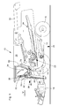
- eine schematische seitliche Ansicht einer selbstfahrenden Erntemaschine in Form eines Mähdreschers mit einer in der Betriebsposition befindlichen Aufstiege,
- Fig. 2
- eine perspektivische Ansicht der Aufstiege der
Figur 1 und eines zum Haltern der Kabine dienenden Rahmenteils der Erntemaschine mit einer daran befestigten, begehbaren Plattform, wobei die Aufstiege sich in der Betriebsposition befindet, - Fig. 3
- die Ansicht nach
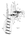
Figur 2 mit in eine Zwischenposition verbrachten Aufstiege, und - Fig. 4
- die Ansicht nach
Figur 2 mit in eine zum Auf- und Absteigen geeignete Außerbetriebsposition verbrachten Aufstiege. - Die
Figur 1 zeigt eine selbstfahrende Arbeitsmaschine 10 in Form eines landwirtschaftlichen Mähdreschers. Die Arbeitsmaschine 10 baut sich auf einer tragenden Struktur 12 mit vorderen, angetriebenen Rädern 14 und rückwärtigen, lenkbaren Rädern 16 auf, mit denen sie in einer Vorwärtsrichtung V über ein Feld bewegbar ist. An der Vorderseite der Arbeitsmaschine 10 ist an einem Schrägförderer 20 ein Erntevorsatz in Form eines Schneidwerks lösbar befestigt, der im Erntebetrieb Erntegut abschneidet und dem Schrägförderer 20 zuführt. Das Erntegut wird dann im Inneren der Arbeitsmaschine 10 von einem Mehrtrommeldreschwerk 22 gedroschen und verbleibendes Korn wird durch einen Hordenschüttler 24 abgeschieden. Das Korn wird in einer Reinigungseinrichtung 26 gereinigt und in einem Korntank 28 abgelegt, aus dem es durch einen Entladeförderer 30 auf ein Transportfahrzeug überladen werden kann. Die Bedienung und Kontrolle der Arbeitsmaschine 10 erfolgt durch einen Bediener von einem in einer Kabine 32 bereitgestellten Bedienerarbeitsplatz aus. Die vorliegende Erfindung kann auch an beliebigen anderen Erntemaschinen, wie Feldhäckslern oder Baumwollpflückern oder Mähfahrzeugen oder anderen Arten von Arbeitsmaschinen, wie Baumaschinen, verwendet werden. Im Folgenden beziehen sich Richtungsangaben, wie vorn, hinten und seitlich, auf die Vorwärtsrichtung V der Arbeitsmaschine. - Die Kabine 32 umfasst eine seitliche, sich nach außen öffnende Tür 34, die sich aus einem äußeren Rahmen und einer darin eingelassenen Scheibe zusammensetzt. Die Tür 34 ist an ihrem vorderen Ende um eine näherungsweise vertikal verlaufende Türschwenkachse 36 beweglich, um dem Bediener einen Zugang zum Innenraum der Kabine 32 zu gewähren. Der Aufstieg zur Kabine 32 erfolgt über eine um eine vertikal verlaufende Drehachse 40 bewegliche Aufstiege 38, die in den
Figuren 1 und2 in einer Betriebsposition, in derFigur 4 in einer Außerbetriebsposition und in derFigur 3 in einer Zwischenposition dargestellt ist, und eine seitlich neben der Tür 34 angeordnete maschinenfeste Plattform 42. Da die Aufstiege 38 um die Drehachse 40 beweglich ist, kann sie in die Betriebsposition verbracht werden, in welcher sich die Aufstiege 38 vor der maschinenfesten Plattform 42 befindet und die Arbeitsmaschine 10 in Betrieb genommen und im Erntebetrieb über ein Feld oder zum Transport über eine Straße bewegt werden kann. In der Betriebsposition befinden sich die maschinenfeste Plattform 42 und die Aufstiege 38 innerhalb einer maximal zulässigen Breite für eine Straßenfahrt, die in Deutschland derzeit 3 m beträgt. In der Außerbetriebsposition wird die Aufstiege 38 hingegen zur Seite hin verschwenkt, sodass sie sich seitlich neben der maschinenfesten Plattform 42 befindet und ein Bediener vom Erdboden über die Aufstiege 38 und die Plattform 42 bei geöffneter Tür 34 in die Kabine 32 gelangen und in umgekehrter Reihenfolge wieder den Erdboden erreichen kann. Die Aufstiege 38 kann auch beim Erntebetrieb in der Außerbetriebsposition verbleiben, damit der Bediener bei eventuellen Störungen schneller an die betreffende Stelle gelangen kann. Die Aufstiege 38 kann in an sich bekannter Weise (s.DE 1 580 314 A1 ) in der Betriebs- und Außerbetriebsposition arretiert werden. - Die Aufstiege 38 umfasst ein Rahmengestell 44, an dessen oberem Ende eine mit der Aufstiege 38 bewegbare Plattform 46 angeordnet ist, unter der sich in der dargestellten Ausführungsform insgesamt sechs Trittstufen 48 befinden. Außerdem trägt das Rahmengestell 44 noch beidseits neben den Trittstufen 48 angeordnete Holme 50, die jeweils am oberen Bereich des Rahmengestells 44 in der Nähe der Plattform 46 und neben der dritten Trittstufe 48 von unten am Rahmengestell 44 angebracht sind. Die Holme 50 bilden einen Handlauf, der auch nach oben über die Plattform 46 hinausragt und dem Bediener einen sicheren Auf- und Abstieg ermöglicht.
- Die maschinenfeste Plattform 42 ist an Rahmenelementen 52 der tragenden Struktur 12 befestigt, die sich parallel zueinander und hintereinander positioniert in Querrichtung der Arbeitsmaschine 10 erstrecken und auch die Kabine 32 an der Struktur 12 haltern. Am rückwärtigen Rahmenelement 52 ist das Rahmengestell 42 durch eine die Drehachse 40 definierende Drehlagerung abgestützt, die einen oberen, am rückwärtigen Rahmenelement 52 befestigten Lagerblock 54 und einen unteren, am Rahmengestell 44 der Aufstiege 38 befestigten Lagerblock 56 umfasst, die durch eine Achse 58 untereinander um die Drehachse 40 schwenkbar verbunden sind. Die Drehachse 40 und die Türschwenkachse 36 befinden sich somit an diagonal gegenüberliegenden Ecken der maschinenfesten Plattform 42, wie sich auch aus einer Gesamtschau der
Figuren 1 und2 ergibt. Die Verschwenkbewegung der Aufstiege 38 erfolgt durch eine Kurbel 60, die über eine Schwenklagerung 64 mit einer horizontalen Achse 66 an einer unteren, sich vertikal erstreckenden Welle 62 befestigt ist. Die Schwenklagerung 64 ermöglicht es, die Kurbel 60 in der Stellung gemäßFigur 4 nach hinten in eine Ruhestellung (nicht gezeigt, s. aberFigur 1 und2 ) zu schwenken, damit sie den Durchgang zur Plattform 46 freigibt. - Die Welle 62 ist ihrerseits der Plattform 46 benachbart durch eine rohrförmige, am Rahmengestell 44 festgelegte Lagerung 68 am Rahmengestell 44 um eine parallel zur Drehachse 40 verlaufende Achse drehbar gelagert. Eine weitere Verbindung zwischen der Welle 62 und der Struktur 12 wird über einen starr am unteren Ende der Welle 62 befestigten Arm 70, eine Strebe 72 und eine am rückwärtigen Rahmenelement 52 befestigte Platte 74 bereitgestellt. Der Arm 70 erstreckt sich radial von der Welle 62 nach außen. Die Strebe 72 ist an ihrem ersten Ende um eine vertikale Achse schwenkbar am Arm 70 und an ihrem zweiten Ende um eine vertikale Achse an der Platte 74 angelenkt. Diese Anordnung bewirkt bei einer Drehung der Kurbel 60 um ca. 180° eine Drehung der Aufstiege 38 um etwa 90° und ermöglicht eine kraftsparende Verstellung der Aufstiege 38 durch den Bediener.
- Oberhalb der Lagerung 68 ist an der Welle 62 eine weitere, gegenüber der Welle 62 frei drehbare Drehlagerung 76 angeordnet, die ein Geländerelement 78 haltert. Das Geländerelement 78 ist über eine äußere Hülse der Drehlagerung 76 mit einem unteren Arm 80 verbunden, der über eine Strebe 82 mit einem Befestigungspunkt am rückwärtigen Rahmenelement 52 gekoppelt ist. Der Arm 80 erstreckt sich radial von der äußeren Hülse der Drehlagerung 76 nach außen. Die Strebe 82 ist an ihrem ersten Ende um eine vertikale Achse schwenkbar am Arm 80 und an ihrem zweiten Ende um eine vertikale Achse schwenkbar am Rahmenelement 52 angelenkt. Diese Anordnung bewirkt, dass das Geländerelement 78 sich am äußeren seitlichen Rand der maschinenfesten Plattform 42 in Fahrtrichtung erstreckt, wenn sich die Aufstiege 38 in der Betriebsposition befindet. Das Geländerelement 78 dreht sich bei Betätigung der Kurbel 60 um die Drehachse 40 gegensinnig zur Aufstiege 38 und erstreckt sich am rückwärtigen Rand der Plattform 46 der Aufstiege 38, wenn sich diese in der Außerbetriebsposition befindet.
- Die Positionierung der Drehachse 40 und der Türschwenkachse ermöglicht es, dass die oberen Bereiche der Holme 50 einen Bogen um die geöffnete Tür 34 herum beschreiben, wenn letztere geöffnet ist. Die Tür 34 kann demnach sowohl geöffnet werden, wenn sich die Aufstiege 38 in der Betriebsposition befindet, als auch wenn sie in der Außerbetriebsposition ist. In beiden Positionen kann die Kurbel 60 problemlos betätigt werden. Die Tür 34 kann in der geöffneten Position ein vorderes, an der Vorderseite der maschinenfesten Plattform 42 angebrachtes Geländer (nicht gezeigt) ersetzen oder ergänzen. Die vorliegende Anordnung ermöglicht es, die Kabine 32 und die Tür 34 derart groß zu bemessen, dass die Tür in geöffneter Stellung seitlich über die Plattform 42 und demnach über die zulässige Breite für eine Straßenfahrt hinausragt.
Claims (10)
- Arbeitsmaschine (10) mit einer in einer Vorwärtsrichtung (V) bewegbaren, tragenden Struktur (12), einer an der tragenden Struktur (12) befestigten Kabine (32), die einen Bedienerarbeitsplatz und eine um eine zumindest etwa vertikale Türschwenkachse (36) nach außen schwenkbare Tür (34) umfasst, einer begehbaren, der Tür (34) seitlich benachbarten, maschinenfesten Plattform (42), und einer gegenüber der maschinenfesten Plattform (42) zwischen einer Betriebsposition und einer begehbaren Außerbetriebsposition bewegbaren Aufstiege (38) mit übereinander angeordneten Trittstufen (48), dadurch gekennzeichnet, dass die Aufstiege (38) um eine zumindest näherungsweise vertikale Drehachse (40) drehbar an der tragenden Struktur (12) abgestützt ist, und dass die Drehachse (40) und die Türschwenkachse (36) an oder in der Nähe von diagonal gegenüberliegenden Ecken der maschinenfesten Plattform (42) positioniert sind.
- Arbeitsmaschine (10) nach Anspruch 1, dadurch gekennzeichnet, dass sich die Türschwenkachse (36) am vorderen Ende der Kabine (32) befindet und dass sich die Drehachse (40) am rückwärtigen, seitlich äußeren Ende der maschinenfesten Plattform (42) befindet, wobei die Trittstufen (48) der Aufstiege (38) in der Außerbetriebsposition in Fahrtrichtung orientiert sind und sich in der Betriebsposition vor oder hinter der maschinenfesten Plattform (42) befinden.
- Arbeitsmaschine (10) nach Anspruch 1 oder 2, dadurch gekennzeichnet, dass die Aufstiege (38) durch eine um die Drehachse (40) drehbare Kurbel (60) gegenüber der maschinenfesten Plattform (42) zwischen der Betriebsposition und der Außerbetriebsposition bewegbar ist.
- Arbeitsmaschine (10) nach Anspruch 3, dadurch gekennzeichnet, dass die Drehbewegung der Kurbel (60) durch eine untersetzende Mechanik auf die Aufstiege (38) übertragen wird.
- Arbeitsmaschine (10) nach Anspruch 3 oder 4, dadurch gekennzeichnet, dass die Kurbel (38) eine drehbar an der Aufstiege (38) gelagerte Welle (62) umfasst, die starr mit einem Arm (70) verbunden ist, der seinerseits durch eine an beiden Enden um eine parallel zur Drehachse (40) schwenkbar angelenkte Strebe (72) mit der tragenden Struktur (12) gekoppelt ist.
- Arbeitsmaschine (10) nach einem der Ansprüche 3 bis 5, dadurch gekennzeichnet, dass die Kurbel (60) gegenüber der Welle (62) um eine horizontale Achse (66) zwischen einer Betätigungs- und einer Ruheposition verschwenkbar ist.
- Arbeitsmaschine (10) nach einem der Ansprüche 1 bis 6, dadurch gekennzeichnet, dass die Aufstiege (38) eine begeh- und bewegbare, der maschinenfesten Plattform (42) benachbarte Plattform (46) umfasst, an deren von der Drehachse (40) beabstandeten Kante die Trittstufen (48) angeordnet sind.
- Arbeitsmaschine (10) nach Anspruch 7, dadurch gekennzeichnet, dass ein Geländerelement (78) der Drehachse (40) benachbart angeordnet und derart bewegungsmäßig mit der Aufstiege (38) gekoppelt ist, dass es sich in der Betriebsstellung der Aufstiege (38) in Vorwärtsrichtung erstreckt und die maschinenfeste Plattform (42) zur Seite hin begrenzt und in der Außerbetriebsstellung der Aufstiege (38) quer zur Vorwärtsrichtung erstreckt und die bewegbare Plattform (46) nach hinten oder vorn begrenzt.
- Arbeitsmaschine (10) nach Anspruch 8, dadurch gekennzeichnet, dass das Geländerelement (78) frei drehbar auf der Welle (62) der Kurbel (60) gelagert und durch einen starr mit dem Geländerelement (78) gekoppelten Arm (80) und eine an beiden Enden um eine parallel zur Drehachse (60) schwenkbar angelenkte Strebe (82) mit der tragenden Struktur (12) gekoppelt ist.
- Arbeitsmaschine (10) nach einem der Ansprüche 1 bis 9, dadurch gekennzeichnet, dass die Tür (34) in geöffneter Position seitlich über die maschinenfeste Plattform (42) hinausragt.
Applications Claiming Priority (1)
| Application Number | Priority Date | Filing Date | Title |
|---|---|---|---|
| DE201110003354 DE102011003354A1 (de) | 2011-01-31 | 2011-01-31 | Aufstiege für eine Arbeitsmaschine |
Publications (2)
| Publication Number | Publication Date |
|---|---|
| EP2481275A1 true EP2481275A1 (de) | 2012-08-01 |
| EP2481275B1 EP2481275B1 (de) | 2014-12-24 |
Family
ID=45315573
Family Applications (1)
| Application Number | Title | Priority Date | Filing Date |
|---|---|---|---|
| EP20110192078 Active EP2481275B1 (de) | 2011-01-31 | 2011-12-06 | Aufstiege für eine Arbeitsmaschine |
Country Status (2)
| Country | Link |
|---|---|
| EP (1) | EP2481275B1 (de) |
| DE (1) | DE102011003354A1 (de) |
Cited By (8)
| Publication number | Priority date | Publication date | Assignee | Title |
|---|---|---|---|---|
| CN104429322A (zh) * | 2014-11-24 | 2015-03-25 | 中联重机股份有限公司 | 一种收获机驾驶梯 |
| WO2017106910A1 (en) * | 2015-12-22 | 2017-06-29 | Barjoh Pty Ltd | Vehicle access device mounted holder for equipment |
| WO2018209284A1 (en) * | 2017-05-12 | 2018-11-15 | Caterpillar Inc. | A construction machine having an ascent means |
| KR102114740B1 (ko) * | 2019-12-31 | 2020-06-08 | (주)비스포크엔지니어링 | 레미콘 차량용 안전장치 |
| BE1027337B1 (de) * | 2019-06-25 | 2021-04-02 | Deere & Co | Arbeitsmaschine mit einer zum Bedienerarbeitsplatz führenden Plattform und/oder Aufstiege |
| KR20210002607U (ko) * | 2020-05-18 | 2021-11-25 | (주)비스포크엔지니어링 | 레미콘 차량용 계단에 적용된 안전장치 |
| CN113863843A (zh) * | 2020-06-30 | 2021-12-31 | 维特根有限公司 | 自行式地面加工机 |
| EP4155130A1 (de) * | 2021-09-27 | 2023-03-29 | Liebherr-Werk Ehingen GmbH | Zugangsvorrichtung für ein arbeitsgerät |
Families Citing this family (1)
| Publication number | Priority date | Publication date | Assignee | Title |
|---|---|---|---|---|
| DE102012216307B3 (de) * | 2012-09-13 | 2014-01-16 | Deere & Company | Aufstiege für eine Arbeitsmaschine |
Citations (7)
| Publication number | Priority date | Publication date | Assignee | Title |
|---|---|---|---|---|
| DE1580314A1 (de) | 1964-02-18 | 1970-03-19 | Massey Ferguson Ltd | Fahrzeug mit erhoeht angeordneter Fahrerplattform |
| FR2141074A5 (de) * | 1971-06-07 | 1973-01-19 | Agrostroj Prostejov Np | |
| DE2531890A1 (de) * | 1975-07-17 | 1977-02-10 | Claas Maschf Gmbh Geb | Fahrerstand fuer selbstfahrende arbeitsmaschinen, insbesondere maehdrescher |
| DE19620072A1 (de) | 1996-05-20 | 1997-11-27 | Krone Bernhard Gmbh Maschf | Aufstiege für ein landwirtschaftliches Trägerfahrzeug |
| US5813494A (en) * | 1995-02-16 | 1998-09-29 | Case Corporation | Access ladder assembly for an off-highway machine |
| US20030230867A1 (en) * | 2002-06-14 | 2003-12-18 | Brockway Robert John | Swing-away stair assembly |
| US20060001251A1 (en) * | 2004-07-01 | 2006-01-05 | Ruppert Rex L | Vehicle drive access and storage device |
-
2011
- 2011-01-31 DE DE201110003354 patent/DE102011003354A1/de not_active Withdrawn
- 2011-12-06 EP EP20110192078 patent/EP2481275B1/de active Active
Patent Citations (7)
| Publication number | Priority date | Publication date | Assignee | Title |
|---|---|---|---|---|
| DE1580314A1 (de) | 1964-02-18 | 1970-03-19 | Massey Ferguson Ltd | Fahrzeug mit erhoeht angeordneter Fahrerplattform |
| FR2141074A5 (de) * | 1971-06-07 | 1973-01-19 | Agrostroj Prostejov Np | |
| DE2531890A1 (de) * | 1975-07-17 | 1977-02-10 | Claas Maschf Gmbh Geb | Fahrerstand fuer selbstfahrende arbeitsmaschinen, insbesondere maehdrescher |
| US5813494A (en) * | 1995-02-16 | 1998-09-29 | Case Corporation | Access ladder assembly for an off-highway machine |
| DE19620072A1 (de) | 1996-05-20 | 1997-11-27 | Krone Bernhard Gmbh Maschf | Aufstiege für ein landwirtschaftliches Trägerfahrzeug |
| US20030230867A1 (en) * | 2002-06-14 | 2003-12-18 | Brockway Robert John | Swing-away stair assembly |
| US20060001251A1 (en) * | 2004-07-01 | 2006-01-05 | Ruppert Rex L | Vehicle drive access and storage device |
Cited By (13)
| Publication number | Priority date | Publication date | Assignee | Title |
|---|---|---|---|---|
| CN104429322B (zh) * | 2014-11-24 | 2016-06-01 | 中联重机股份有限公司 | 一种收获机驾驶梯 |
| CN104429322A (zh) * | 2014-11-24 | 2015-03-25 | 中联重机股份有限公司 | 一种收获机驾驶梯 |
| AU2016374653B2 (en) * | 2015-12-22 | 2022-03-10 | Barjoh Pty Ltd | Vehicle access device mounted holder for equipment |
| WO2017106910A1 (en) * | 2015-12-22 | 2017-06-29 | Barjoh Pty Ltd | Vehicle access device mounted holder for equipment |
| JP2019500266A (ja) * | 2015-12-22 | 2019-01-10 | バージョー ピーティーワイ リミテッド | 車両乗降デバイスに取り付けられる備品用ホルダー |
| US11332977B2 (en) | 2015-12-22 | 2022-05-17 | Barjoh Pty Ltd | Vehicle access device mounted holder for equipment |
| WO2018209284A1 (en) * | 2017-05-12 | 2018-11-15 | Caterpillar Inc. | A construction machine having an ascent means |
| BE1027337B1 (de) * | 2019-06-25 | 2021-04-02 | Deere & Co | Arbeitsmaschine mit einer zum Bedienerarbeitsplatz führenden Plattform und/oder Aufstiege |
| KR102114740B1 (ko) * | 2019-12-31 | 2020-06-08 | (주)비스포크엔지니어링 | 레미콘 차량용 안전장치 |
| KR20210002607U (ko) * | 2020-05-18 | 2021-11-25 | (주)비스포크엔지니어링 | 레미콘 차량용 계단에 적용된 안전장치 |
| KR200495210Y1 (ko) | 2020-05-18 | 2022-04-01 | (주)비스포크엔지니어링 | 레미콘 차량용 계단에 적용된 안전장치 |
| CN113863843A (zh) * | 2020-06-30 | 2021-12-31 | 维特根有限公司 | 自行式地面加工机 |
| EP4155130A1 (de) * | 2021-09-27 | 2023-03-29 | Liebherr-Werk Ehingen GmbH | Zugangsvorrichtung für ein arbeitsgerät |
Also Published As
| Publication number | Publication date |
|---|---|
| EP2481275B1 (de) | 2014-12-24 |
| DE102011003354A1 (de) | 2012-08-02 |
Similar Documents
| Publication | Publication Date | Title |
|---|---|---|
| EP2481275B1 (de) | Aufstiege für eine Arbeitsmaschine | |
| DE102005016350A1 (de) | Erntevorsatz für landwirtschaftliche Erntemaschinen | |
| EP1444881A2 (de) | Antriebssystem für einen Erntevorsatz einer Erntemaschine | |
| EP1468598A2 (de) | Feldhäcksler mit positionierbarer Fahrerkabine | |
| DE102010028687B4 (de) | Erntevorsatz mit zwischen einer Transportstellung und einer Erntestellung bewegbaren Beleuchtungseinrichtung für die Straßenfahrt | |
| EP0432632B1 (de) | Erntemaschine, insbesondere selbstfahrender Mähdrescher | |
| EP2591653B1 (de) | Heuwerbungsmaschine | |
| DE102007035796B4 (de) | Vorrichtung zur Arretierung eines Wagens zur Abstützung eines Erntevorsatzes bei einer Straßenfahrt an dem Erntevorsatz | |
| DE102012216307B3 (de) | Aufstiege für eine Arbeitsmaschine | |
| EP1894462B1 (de) | Landwirtschaftliches Trägerfahrzeug | |
| DE900555C (de) | Hubstapler-Selbstfahrer | |
| EP1714603B1 (de) | Bodenreinigungsmaschine | |
| DE102004059038B4 (de) | Kombination aus einer Erntemaschine, einem Erntevorsatz und einem Wagen zur Abstützung des Erntevorsatzes | |
| DE102014209203B4 (de) | Für eine Straßenfahrt temporär an einem Erntevorsatz anbringbare Vorrichtung zur seitlichen Abdeckung des Erntevorsatzes bei einer Straßenfahrt | |
| DE102004015164B4 (de) | Wagen zur Abstützung eines Erntevorsatzes | |
| DE1756516C3 (de) | Paletten- oder Regalstapler | |
| DE69519132T2 (de) | Zugangsvorrichtung für landwirtschaftliche Erntemaschine | |
| EP0055243A1 (de) | Fahrzeug zur Wartung von Flugzeugen | |
| DE3713474A1 (de) | Heuwerbungsmaschine | |
| DE102021102774A1 (de) | Mähwerksanordnung | |
| DE102020113952A1 (de) | Arbeitsmaschine mit beweglicher Aufstiegsleiter | |
| BE1031908B1 (de) | Erntevorsatz für eine selbstfahrende Erntemaschine | |
| AT523600B1 (de) | Mähwerksanordnung | |
| DE19805399A1 (de) | Erntegutbergungsvorsatz | |
| DE102017204249A1 (de) | Kombination aus einem landwirtschaftlichen Arbeitsgerät und einem Straßenfahrschutz mit Abdeck-, Warn und/oder Beleuchtungseinrichtungen zur Absicherung des Arbeitsgeräts bei einer Straßenfahrt |
Legal Events
| Date | Code | Title | Description |
|---|---|---|---|
| PUAI | Public reference made under article 153(3) epc to a published international application that has entered the european phase |
Free format text: ORIGINAL CODE: 0009012 |
|
| AK | Designated contracting states |
Kind code of ref document: A1 Designated state(s): AL AT BE BG CH CY CZ DE DK EE ES FI FR GB GR HR HU IE IS IT LI LT LU LV MC MK MT NL NO PL PT RO RS SE SI SK SM TR |
|
| AX | Request for extension of the european patent |
Extension state: BA ME |
|
| 17P | Request for examination filed |
Effective date: 20130201 |
|
| GRAP | Despatch of communication of intention to grant a patent |
Free format text: ORIGINAL CODE: EPIDOSNIGR1 |
|
| INTG | Intention to grant announced |
Effective date: 20140808 |
|
| GRAS | Grant fee paid |
Free format text: ORIGINAL CODE: EPIDOSNIGR3 |
|
| GRAA | (expected) grant |
Free format text: ORIGINAL CODE: 0009210 |
|
| AK | Designated contracting states |
Kind code of ref document: B1 Designated state(s): AL AT BE BG CH CY CZ DE DK EE ES FI FR GB GR HR HU IE IS IT LI LT LU LV MC MK MT NL NO PL PT RO RS SE SI SK SM TR |
|
| REG | Reference to a national code |
Ref country code: GB Ref legal event code: FG4D Free format text: NOT ENGLISH |
|
| REG | Reference to a national code |
Ref country code: CH Ref legal event code: EP |
|
| REG | Reference to a national code |
Ref country code: IE Ref legal event code: FG4D Free format text: LANGUAGE OF EP DOCUMENT: GERMAN |
|
| REG | Reference to a national code |
Ref country code: AT Ref legal event code: REF Ref document number: 702634 Country of ref document: AT Kind code of ref document: T Effective date: 20150115 |
|
| REG | Reference to a national code |
Ref country code: DE Ref legal event code: R096 Ref document number: 502011005379 Country of ref document: DE Effective date: 20150219 |
|
| REG | Reference to a national code |
Ref country code: NL Ref legal event code: VDEP Effective date: 20141224 |
|
| PG25 | Lapsed in a contracting state [announced via postgrant information from national office to epo] |
Ref country code: FI Free format text: LAPSE BECAUSE OF FAILURE TO SUBMIT A TRANSLATION OF THE DESCRIPTION OR TO PAY THE FEE WITHIN THE PRESCRIBED TIME-LIMIT Effective date: 20141224 Ref country code: NO Free format text: LAPSE BECAUSE OF FAILURE TO SUBMIT A TRANSLATION OF THE DESCRIPTION OR TO PAY THE FEE WITHIN THE PRESCRIBED TIME-LIMIT Effective date: 20150324 Ref country code: LT Free format text: LAPSE BECAUSE OF FAILURE TO SUBMIT A TRANSLATION OF THE DESCRIPTION OR TO PAY THE FEE WITHIN THE PRESCRIBED TIME-LIMIT Effective date: 20141224 |
|
| REG | Reference to a national code |
Ref country code: LT Ref legal event code: MG4D |
|
| PG25 | Lapsed in a contracting state [announced via postgrant information from national office to epo] |
Ref country code: SE Free format text: LAPSE BECAUSE OF FAILURE TO SUBMIT A TRANSLATION OF THE DESCRIPTION OR TO PAY THE FEE WITHIN THE PRESCRIBED TIME-LIMIT Effective date: 20141224 Ref country code: GR Free format text: LAPSE BECAUSE OF FAILURE TO SUBMIT A TRANSLATION OF THE DESCRIPTION OR TO PAY THE FEE WITHIN THE PRESCRIBED TIME-LIMIT Effective date: 20150325 Ref country code: RS Free format text: LAPSE BECAUSE OF FAILURE TO SUBMIT A TRANSLATION OF THE DESCRIPTION OR TO PAY THE FEE WITHIN THE PRESCRIBED TIME-LIMIT Effective date: 20141224 Ref country code: HR Free format text: LAPSE BECAUSE OF FAILURE TO SUBMIT A TRANSLATION OF THE DESCRIPTION OR TO PAY THE FEE WITHIN THE PRESCRIBED TIME-LIMIT Effective date: 20141224 Ref country code: LV Free format text: LAPSE BECAUSE OF FAILURE TO SUBMIT A TRANSLATION OF THE DESCRIPTION OR TO PAY THE FEE WITHIN THE PRESCRIBED TIME-LIMIT Effective date: 20141224 |
|
| PG25 | Lapsed in a contracting state [announced via postgrant information from national office to epo] |
Ref country code: NL Free format text: LAPSE BECAUSE OF FAILURE TO SUBMIT A TRANSLATION OF THE DESCRIPTION OR TO PAY THE FEE WITHIN THE PRESCRIBED TIME-LIMIT Effective date: 20141224 |
|
| PG25 | Lapsed in a contracting state [announced via postgrant information from national office to epo] |
Ref country code: ES Free format text: LAPSE BECAUSE OF FAILURE TO SUBMIT A TRANSLATION OF THE DESCRIPTION OR TO PAY THE FEE WITHIN THE PRESCRIBED TIME-LIMIT Effective date: 20141224 Ref country code: SK Free format text: LAPSE BECAUSE OF FAILURE TO SUBMIT A TRANSLATION OF THE DESCRIPTION OR TO PAY THE FEE WITHIN THE PRESCRIBED TIME-LIMIT Effective date: 20141224 Ref country code: EE Free format text: LAPSE BECAUSE OF FAILURE TO SUBMIT A TRANSLATION OF THE DESCRIPTION OR TO PAY THE FEE WITHIN THE PRESCRIBED TIME-LIMIT Effective date: 20141224 Ref country code: RO Free format text: LAPSE BECAUSE OF FAILURE TO SUBMIT A TRANSLATION OF THE DESCRIPTION OR TO PAY THE FEE WITHIN THE PRESCRIBED TIME-LIMIT Effective date: 20141224 Ref country code: CZ Free format text: LAPSE BECAUSE OF FAILURE TO SUBMIT A TRANSLATION OF THE DESCRIPTION OR TO PAY THE FEE WITHIN THE PRESCRIBED TIME-LIMIT Effective date: 20141224 |
|
| PG25 | Lapsed in a contracting state [announced via postgrant information from national office to epo] |
Ref country code: PL Free format text: LAPSE BECAUSE OF FAILURE TO SUBMIT A TRANSLATION OF THE DESCRIPTION OR TO PAY THE FEE WITHIN THE PRESCRIBED TIME-LIMIT Effective date: 20141224 Ref country code: IS Free format text: LAPSE BECAUSE OF FAILURE TO SUBMIT A TRANSLATION OF THE DESCRIPTION OR TO PAY THE FEE WITHIN THE PRESCRIBED TIME-LIMIT Effective date: 20150424 |
|
| REG | Reference to a national code |
Ref country code: DE Ref legal event code: R097 Ref document number: 502011005379 Country of ref document: DE |
|
| PG25 | Lapsed in a contracting state [announced via postgrant information from national office to epo] |
Ref country code: DK Free format text: LAPSE BECAUSE OF FAILURE TO SUBMIT A TRANSLATION OF THE DESCRIPTION OR TO PAY THE FEE WITHIN THE PRESCRIBED TIME-LIMIT Effective date: 20141224 |
|
| PLBE | No opposition filed within time limit |
Free format text: ORIGINAL CODE: 0009261 |
|
| STAA | Information on the status of an ep patent application or granted ep patent |
Free format text: STATUS: NO OPPOSITION FILED WITHIN TIME LIMIT |
|
| 26N | No opposition filed |
Effective date: 20150925 |
|
| PG25 | Lapsed in a contracting state [announced via postgrant information from national office to epo] |
Ref country code: SI Free format text: LAPSE BECAUSE OF FAILURE TO SUBMIT A TRANSLATION OF THE DESCRIPTION OR TO PAY THE FEE WITHIN THE PRESCRIBED TIME-LIMIT Effective date: 20141224 |
|
| PG25 | Lapsed in a contracting state [announced via postgrant information from national office to epo] |
Ref country code: MC Free format text: LAPSE BECAUSE OF FAILURE TO SUBMIT A TRANSLATION OF THE DESCRIPTION OR TO PAY THE FEE WITHIN THE PRESCRIBED TIME-LIMIT Effective date: 20141224 Ref country code: LU Free format text: LAPSE BECAUSE OF FAILURE TO SUBMIT A TRANSLATION OF THE DESCRIPTION OR TO PAY THE FEE WITHIN THE PRESCRIBED TIME-LIMIT Effective date: 20151206 |
|
| REG | Reference to a national code |
Ref country code: CH Ref legal event code: PL |
|
| GBPC | Gb: european patent ceased through non-payment of renewal fee |
Effective date: 20151206 |
|
| REG | Reference to a national code |
Ref country code: IE Ref legal event code: MM4A |
|
| REG | Reference to a national code |
Ref country code: FR Ref legal event code: ST Effective date: 20160831 |
|
| PG25 | Lapsed in a contracting state [announced via postgrant information from national office to epo] |
Ref country code: LI Free format text: LAPSE BECAUSE OF NON-PAYMENT OF DUE FEES Effective date: 20151231 Ref country code: IE Free format text: LAPSE BECAUSE OF NON-PAYMENT OF DUE FEES Effective date: 20151206 Ref country code: CH Free format text: LAPSE BECAUSE OF NON-PAYMENT OF DUE FEES Effective date: 20151231 Ref country code: GB Free format text: LAPSE BECAUSE OF NON-PAYMENT OF DUE FEES Effective date: 20151206 |
|
| PG25 | Lapsed in a contracting state [announced via postgrant information from national office to epo] |
Ref country code: FR Free format text: LAPSE BECAUSE OF NON-PAYMENT OF DUE FEES Effective date: 20151231 |
|
| PG25 | Lapsed in a contracting state [announced via postgrant information from national office to epo] |
Ref country code: IT Free format text: LAPSE BECAUSE OF NON-PAYMENT OF DUE FEES Effective date: 20151206 |
|
| PG25 | Lapsed in a contracting state [announced via postgrant information from national office to epo] |
Ref country code: BG Free format text: LAPSE BECAUSE OF FAILURE TO SUBMIT A TRANSLATION OF THE DESCRIPTION OR TO PAY THE FEE WITHIN THE PRESCRIBED TIME-LIMIT Effective date: 20141224 Ref country code: HU Free format text: LAPSE BECAUSE OF FAILURE TO SUBMIT A TRANSLATION OF THE DESCRIPTION OR TO PAY THE FEE WITHIN THE PRESCRIBED TIME-LIMIT; INVALID AB INITIO Effective date: 20111206 |
|
| PG25 | Lapsed in a contracting state [announced via postgrant information from national office to epo] |
Ref country code: CY Free format text: LAPSE BECAUSE OF FAILURE TO SUBMIT A TRANSLATION OF THE DESCRIPTION OR TO PAY THE FEE WITHIN THE PRESCRIBED TIME-LIMIT Effective date: 20141224 |
|
| PG25 | Lapsed in a contracting state [announced via postgrant information from national office to epo] |
Ref country code: SM Free format text: LAPSE BECAUSE OF FAILURE TO SUBMIT A TRANSLATION OF THE DESCRIPTION OR TO PAY THE FEE WITHIN THE PRESCRIBED TIME-LIMIT Effective date: 20141224 |
|
| PG25 | Lapsed in a contracting state [announced via postgrant information from national office to epo] |
Ref country code: IT Free format text: LAPSE BECAUSE OF NON-PAYMENT OF DUE FEES Effective date: 20151206 Ref country code: TR Free format text: LAPSE BECAUSE OF FAILURE TO SUBMIT A TRANSLATION OF THE DESCRIPTION OR TO PAY THE FEE WITHIN THE PRESCRIBED TIME-LIMIT Effective date: 20141224 Ref country code: MT Free format text: LAPSE BECAUSE OF FAILURE TO SUBMIT A TRANSLATION OF THE DESCRIPTION OR TO PAY THE FEE WITHIN THE PRESCRIBED TIME-LIMIT Effective date: 20141224 |
|
| PGRI | Patent reinstated in contracting state [announced from national office to epo] |
Ref country code: IT Effective date: 20170710 |
|
| REG | Reference to a national code |
Ref country code: AT Ref legal event code: MM01 Ref document number: 702634 Country of ref document: AT Kind code of ref document: T Effective date: 20161206 |
|
| PG25 | Lapsed in a contracting state [announced via postgrant information from national office to epo] |
Ref country code: AT Free format text: LAPSE BECAUSE OF NON-PAYMENT OF DUE FEES Effective date: 20161206 |
|
| PG25 | Lapsed in a contracting state [announced via postgrant information from national office to epo] |
Ref country code: MK Free format text: LAPSE BECAUSE OF FAILURE TO SUBMIT A TRANSLATION OF THE DESCRIPTION OR TO PAY THE FEE WITHIN THE PRESCRIBED TIME-LIMIT Effective date: 20141224 |
|
| PG25 | Lapsed in a contracting state [announced via postgrant information from national office to epo] |
Ref country code: PT Free format text: LAPSE BECAUSE OF FAILURE TO SUBMIT A TRANSLATION OF THE DESCRIPTION OR TO PAY THE FEE WITHIN THE PRESCRIBED TIME-LIMIT Effective date: 20141224 |
|
| PG25 | Lapsed in a contracting state [announced via postgrant information from national office to epo] |
Ref country code: AL Free format text: LAPSE BECAUSE OF FAILURE TO SUBMIT A TRANSLATION OF THE DESCRIPTION OR TO PAY THE FEE WITHIN THE PRESCRIBED TIME-LIMIT Effective date: 20141224 |
|
| PGFP | Annual fee paid to national office [announced via postgrant information from national office to epo] |
Ref country code: IT Payment date: 20221221 Year of fee payment: 12 |
|
| PGFP | Annual fee paid to national office [announced via postgrant information from national office to epo] |
Ref country code: BE Payment date: 20231227 Year of fee payment: 13 |
|
| PG25 | Lapsed in a contracting state [announced via postgrant information from national office to epo] |
Ref country code: IT Free format text: LAPSE BECAUSE OF NON-PAYMENT OF DUE FEES Effective date: 20231206 |
|
| REG | Reference to a national code |
Ref country code: BE Ref legal event code: MM Effective date: 20241231 |
|
| PG25 | Lapsed in a contracting state [announced via postgrant information from national office to epo] |
Ref country code: BE Free format text: LAPSE BECAUSE OF NON-PAYMENT OF DUE FEES Effective date: 20241231 |
|
| PGFP | Annual fee paid to national office [announced via postgrant information from national office to epo] |
Ref country code: DE Payment date: 20251119 Year of fee payment: 15 |