EP2476633A1 - Kapsel, System und Verfahren für die Zubereitung eines Getränks - Google Patents
Kapsel, System und Verfahren für die Zubereitung eines Getränks Download PDFInfo
- Publication number
- EP2476633A1 EP2476633A1 EP10195723A EP10195723A EP2476633A1 EP 2476633 A1 EP2476633 A1 EP 2476633A1 EP 10195723 A EP10195723 A EP 10195723A EP 10195723 A EP10195723 A EP 10195723A EP 2476633 A1 EP2476633 A1 EP 2476633A1
- Authority
- EP
- European Patent Office
- Prior art keywords
- capsule
- beverage
- region
- lid
- substance
- Prior art date
- Legal status (The legal status is an assumption and is not a legal conclusion. Google has not performed a legal analysis and makes no representation as to the accuracy of the status listed.)
- Granted
Links
Images


Classifications
-
- B—PERFORMING OPERATIONS; TRANSPORTING
- B65—CONVEYING; PACKING; STORING; HANDLING THIN OR FILAMENTARY MATERIAL
- B65D—CONTAINERS FOR STORAGE OR TRANSPORT OF ARTICLES OR MATERIALS, e.g. BAGS, BARRELS, BOTTLES, BOXES, CANS, CARTONS, CRATES, DRUMS, JARS, TANKS, HOPPERS, FORWARDING CONTAINERS; ACCESSORIES, CLOSURES, OR FITTINGS THEREFOR; PACKAGING ELEMENTS; PACKAGES
- B65D85/00—Containers, packaging elements or packages, specially adapted for particular articles or materials
- B65D85/70—Containers, packaging elements or packages, specially adapted for particular articles or materials for materials not otherwise provided for
- B65D85/804—Disposable containers or packages with contents which are mixed, infused or dissolved in situ, i.e. without having been previously removed from the package
-
- A—HUMAN NECESSITIES
- A47—FURNITURE; DOMESTIC ARTICLES OR APPLIANCES; COFFEE MILLS; SPICE MILLS; SUCTION CLEANERS IN GENERAL
- A47J—KITCHEN EQUIPMENT; COFFEE MILLS; SPICE MILLS; APPARATUS FOR MAKING BEVERAGES
- A47J31/00—Apparatus for making beverages
- A47J31/40—Beverage-making apparatus with dispensing means for adding a measured quantity of ingredients, e.g. coffee, water, sugar, cocoa, milk, tea
- A47J31/407—Beverage-making apparatus with dispensing means for adding a measured quantity of ingredients, e.g. coffee, water, sugar, cocoa, milk, tea with ingredient-containing cartridges; Cartridge-perforating means
-
- B—PERFORMING OPERATIONS; TRANSPORTING
- B65—CONVEYING; PACKING; STORING; HANDLING THIN OR FILAMENTARY MATERIAL
- B65D—CONTAINERS FOR STORAGE OR TRANSPORT OF ARTICLES OR MATERIALS, e.g. BAGS, BARRELS, BOTTLES, BOXES, CANS, CARTONS, CRATES, DRUMS, JARS, TANKS, HOPPERS, FORWARDING CONTAINERS; ACCESSORIES, CLOSURES, OR FITTINGS THEREFOR; PACKAGING ELEMENTS; PACKAGES
- B65D85/00—Containers, packaging elements or packages, specially adapted for particular articles or materials
- B65D85/70—Containers, packaging elements or packages, specially adapted for particular articles or materials for materials not otherwise provided for
- B65D85/804—Disposable containers or packages with contents which are mixed, infused or dissolved in situ, i.e. without having been previously removed from the package
- B65D85/8043—Packages adapted to allow liquid to pass through the contents
- B65D85/8046—Pods, i.e. closed containers made only of filter paper or similar material
-
- B—PERFORMING OPERATIONS; TRANSPORTING
- B65—CONVEYING; PACKING; STORING; HANDLING THIN OR FILAMENTARY MATERIAL
- B65D—CONTAINERS FOR STORAGE OR TRANSPORT OF ARTICLES OR MATERIALS, e.g. BAGS, BARRELS, BOTTLES, BOXES, CANS, CARTONS, CRATES, DRUMS, JARS, TANKS, HOPPERS, FORWARDING CONTAINERS; ACCESSORIES, CLOSURES, OR FITTINGS THEREFOR; PACKAGING ELEMENTS; PACKAGES
- B65D65/00—Wrappers or flexible covers; Packaging materials of special type or form
- B65D65/38—Packaging materials of special type or form
- B65D65/46—Applications of disintegrable, dissolvable or edible materials
- B65D65/466—Bio- or photodegradable packaging materials
Definitions
- the present invention relates to a capsule according to the preamble of claim 1 and a method for beverage production.
- Such capsules which in particular are used only once and disposed of after use for beverage production, are now widely used as portion packs for the preparation of, for example, coffee or tea. For example, the consumer no longer has to worry about dosing the right quantity of coffee, and after the extraction process, the capsule and its contents can be disposed of.
- a cartridge containing a substance for making a beverage with a machine is known.
- This cartridge has a substantially dense body with an acute-angled truncated cone shape, this cartridge is usually made of aluminum sheet.
- a plastic capsule containing a substance for making a beverage with a machine is known.
- a stiffening zone is arranged to prevent the soil bends unduly in the construction of the tensile stress immediately before penetration.
- the capsule according to the invention consists of a capsule body with a side wall and with a bottom integrally formed with the side wall.
- the capsule body is rotationally symmetrical.
- the capsule comprises a cover covering the capsule body to form a closed chamber containing a substance for the preparation of a beverage.
- At least the bottom is penetrable for the passage of a liquid through the chamber with a device arranged outside the capsule at a penetration area of the soil.
- the floor has a stiffening area.
- a central region of the bottom is formed as a penetration region, wherein the stiffening region is arranged around the penetration region.
- the floor is preferably formed dome-shaped.
- the stiffening region is rotationally symmetrical arranged around the penetration area.
- the stiffening region is designed as at least one section-wise depression substantially in the circumferential direction in the bottom. In other words, the stiffening region has one or more sectional depressions substantially in the circumferential direction in the ground.
- a depression on an outer side of the capsule is formed from here. understood the remote from the closed chamber side of the capsule.
- the bottom has depressions
- the depressions which are also referred to as indentations, are an integral part of the soil.
- Wells in the sense of the present application are therefore not recesses between external elements on the ground, which are attached for example to this outside.
- the capsule according to the invention now has the advantage that the capsule can be reliably penetrated through the stiffening region with partial depressions in the bottom by commercially available devices for producing drinks, so that beverage production is made possible.
- the capsule is also inexpensive to produce, since the stiffening region is formed as an integral part of the capsule and thus the capsule can be produced for example by means of a deep-drawing process.
- Section-wise recesses have the advantage, in particular with respect to circumferential recesses or even circumferential ribs on or in the bottom, that they bring about a better stiffening effect. Circumferential depressions or circumferential ribs in the soil thus often lead to insufficient stiffening.
- a penetration zone is understood to be a particularly continuous region of the soil which is penetrated by the device for penetration.
- a stiffening region is understood to mean a region of the bottom in which the depressions are arranged for stiffening.
- a central area of the floor is understood hereunder and below to mean that this area represents a particularly continuous area and at least includes the geometric center of the capsule floor.
- rotationally symmetric is understood here and below to mean a symmetry with respect to rotation about the longitudinal axis of the capsule at a discrete angle or else at any angle.
- This arrangement of the penetration region in a central region of the bottom with a stiffening region arranged around it has the advantage that a very good stiffening of the penetration region can be achieved thereby, so that the capsule can be reliably penetrated with the device for penetrating the device for producing beverages.
- the recess has at least two mutually inclined wall sections.
- the at least one section-wise depression is step-shaped and / or in a sectional plane running along the longitudinal axis of the capsule body, i. formed by the depression, L-shaped.
- an arm of the L-shape lies substantially parallel to the longitudinal axis of the capsule body.
- this arm of the L-shape with the longitudinal axis encloses an angle in the range of +/- 20 °, preferably of +/- 10 ° and most preferably of +/- 5 °.
- This embodiment of the at least one recess of the capsule has the advantage that a particularly good stiffening of the capsule bottom can be achieved by the step-shaped or L-shaped design of the section-wise depression. Thereby, a reliable penetration of the soil is achieved by means of the device for penetrating the device for beverage production.
- the section-wise depression has at least one surface section parallel to a cutting plane running along the longitudinal axis of the capsule body through the depression or closes with this section plane an angle in the range of +/- 45 °, preferably +/- 30 °, and most preferably of +/- 15 °.
- an angle in the range of +/- 10 ° and more preferably of +/- 5 ° is included.
- This embodiment of the at least one recess of the capsule has the advantage that a further improved stiffening is made possible by the formation of the sectional recess by means of the orientation of the surface portion.
- the cutting plane runs along the longitudinal axis of the capsule body through the center of the peripheral portion of the depression facing the central region of the bottom.
- the soil has at least two wells and preferably three to ten wells.
- This embodiment has the advantage that, due to the selectable number of depressions in the base for stiffening, adaptation to the respective requirements with regard to rigidity of the floor is possible.
- the number of depressions can be made, for example, depending on the selected material of the capsule body or depending on the device for beverage production in which the capsule is to be used.
- the bottom is formed between the recesses as a particular triangular web.
- the capsule wall has at least one inside projection as a stacking shoulder.
- the capsule wall has two and more preferably at least three inside projections.
- the capsule wall in particular complementary outer side recesses on the inside projections.
- the capsule wall has complementary outer side recesses to the inside projections, it is understood here and in the following that the outside recesses are located at the same positions as the inside projections of the capsule wall.
- This embodiment of the capsule wall with inside projections has the advantage that the not yet filled capsule body are stackable and due to the inside projections are easily separable again, since wedging the stacked capsules is prevented.
- This has the advantage that, for example, in a production line for bottling coffee, the capsule body can be reliably separated.
- the capsule body can be removed automatically from a stack by means of a gripping arm, so that in each case reliably only one capsule is introduced into the filling device.
- the inside projections are circumferentially spaced from each other.
- the inside projections are circumferentially spaced from each other, it is understood hereunder and hereinafter that the projections on the inside do not completely overlap on a projection along the capsule wall parallel to the longitudinal axis of the capsule.
- This arrangement of the inside projections has the advantage that the capsule bodies are easily and reliably separated from each other when they are stacked on each other.
- the outside recesses also have the advantage that the capsule body is on the outside well tangible by appropriate means of the filling device.
- the capsule body preferably consists of plastic and particularly preferably of at least one biopolymer.
- plastic is understood to mean an organic polymer which is essentially produced from organic molecules or else a biopolymer and any desired combinations of these materials.
- a biopolymer is understood as meaning a naturally occurring polymer and in particular a biodegradable biopolymer.
- the capsule body is at least two polymer layers.
- the capsule body is produced by means of a deep-drawing process, wherein particularly preferably an outer layer of the capsule body consists of polyethylene.
- the production of the capsule body from at least two polymer layers has the advantage that they can be selected according to the intended use, for example, depending on the device to be used for beverage production. Due to the layer structure of the capsule body can also be selected which properties should have, for example, in terms of softness, the outer or inner layer.
- one of the layers is made of polyethylene and the other of polypropylene.
- one of the layers may be ethylene vinyl alcohol.
- the capsule body consists of at least three layers, more preferably at least four layers, and most preferably at least five layers.
- these layers each consist of one of the following materials or any combination thereof: polypropylene, polyethylene, ethylene-vinyl alcohol.
- the production of the capsule body by means of a deep-drawing process has the advantage that the production of the capsule body by means of this method is inexpensive and allows a high throughput through the deep-drawing device.
- the capsule body has a laterally projecting beyond the capsule wall flange for fixing the lid.
- the flange has the advantage of improving the positioning of the capsule in the beverage making apparatus.
- the lid is preferably formed from an aluminum foil, a perforated foil or filter paper.
- the lid can also be formed from any combination of aluminum foil, perforated foil and filter paper.
- the use of aluminum foil as a lid has the advantage that in this way the capsule is substantially hermetically sealable and thus the capsule is aroma-tight.
- the packaging of the capsule for sale in an additional, airtight envelope is not necessary, which is inexpensive and simplifies the handling of the capsule for beverage production.
- a perforated foil and / or filter paper as a lid has the advantage that no means for perforating or tearing the lid are required in the device for beverage production for discharging the beverage through the lid.
- the perforation of the film or the filter openings of the filter paper can be chosen so that an optimal flow of liquid through the capsule is achieved to achieve a high quality of the beverage produced.
- Another aspect of the present invention relates to a capsule body for a capsule as described above.
- Another aspect of the present invention is directed to a sachet comprising a capsule filled with a substance as described above.
- this capsule contains coffee.
- the capsule is enclosed by a substantially airtight envelope.
- the capsule in the sachet corresponds to the capsule described above and therefore has its advantages.
- This portion packaging has the advantage that the capsule can be closed aroma-tight, which is particularly advantageous in coffee.
- This sheath is particularly advantageously used when using a perforated foil or filter paper as a lid as described above, in order to make the capsule aroma-tight for storage and transportation, i. essentially airtight, to close.
- Even when using an aluminum foil the use of the casing for substantially airtight sealing may be advantageous if the aluminum foil has damage or is not substantially airtight connected to the capsule body.
- An additional aspect of the present invention is directed to a system comprising a capsule filled with a substance as described above or with a sachet such as described above. Furthermore, the system comprises a beverage production device, wherein the beverage production device comprises a capsule holder for receiving the capsule and means for penetrating a bottom of the capsule. Furthermore, the beverage production device has a device for supplying a liquid into the capsule for extracting the substance for the production of a beverage. The drink is removable through a lid of the capsule.
- This system comprises a capsule as described above and therefore has all the advantages described above.
- the beverage production device has a device for discharging the beverage, for example into a drinking container.
- the beverage production device additionally comprises a tearing device, so that the beverage can be discharged through the lid.
- An additional aspect of the present invention is directed to the use of a coffee-filled capsule as described above or portioned packaging as described above for making a coffee beverage.
- Another aspect of the present invention is directed to a process for making beverages.
- a first step of the method the insertion of a capsule filled with a substance as described above takes place in a capsule holder of a beverage production device.
- a penetration of a bottom of the capsule by means of a device for penetrating the beverage production device takes place.
- a liquid is fed into the capsule under a pressure in the range of 1 bar to 20 bar.
- the liquid is in particular heated, which is in particular water.
- a beverage is extracted from the substance in the capsule.
- the beverage is removed through a lid of the capsule.
- the lid has openings for the discharge of the drink.
- the lid is torn open by the supplied liquid in cooperation with a Aufreiss adopted the beverage production device for discharging the drink.
- FIG. 1 is a side view of an inventive capsule 1 perpendicular to the longitudinal axis 22 of the capsule 1 is shown.
- the capsule 1 has a capsule body 2 with a side wall 3 and with an integrally formed with this bottom 4.
- the bottom 4 is formed dome-shaped.
- the capsule 1 on a cover 5, which consists of an aluminum foil, which not perforated.
- the lid 5 is attached to a flange 13.
- the capsule body 2 and the lid 5 form a closed chamber 6, in which a substance, not shown here, is filled, in which this is coffee.
- the capsule body 2 has in the bottom 4 of the capsule body 2 a penetration region 9 and a stiffening region 10.
- the stiffening region 10 is arranged around the penetration region 9.
- the bottom 4 has depressions 8 in sections. Between these section-wise depressions 8, the bottom 4 in the stiffening region 10 in the form of triangular webs 21 is formed for better stiffening of the bottom 4 of the capsule 1.
- the section-wise depressions 8 in the stiffening region 10 are step-shaped.
- a surface portion of the recess 8 encloses with the cutting plane parallel to the longitudinal axis 22 at an angle a of 10 °.
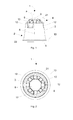
- FIG. 2 is a plan view of the inventive capsule according to FIG. 1 represented parallel to the longitudinal axis of the capsule 1.
- the same reference characters denote the same features in all figures and are therefore only explained again when needed.
- the stiffening region 10 is rotationally symmetrical with respect to discrete angles about the penetration region 9, ie with respect to rotations about substantially 1/8 of a full rotation through 360 °.
- FIG. 3 is a capsule according to the invention 1 in a cross section according to FIG. 1 shown containing a substance 7.
- the capsule 1 comprises a capsule body 2 with a side wall 3. To a flange 13, a perforated lid 5 is attached to form the closed chamber 6, in which the substance 7 is received.
- the section-wise depressions 8 are step-shaped and, in a sectional plane parallel to the longitudinal axis 22 of the capsule body, have an L-shape.
- An arm 23 of the L-shape of the section-wise depression 8 encloses an angle b of 5 ° with the longitudinal axis 22.
- FIG. 4 is a perspective view of a capsule body 2 according to above FIG. 1 shown. Clearly visible here are the inverted, section-wise recesses 8.
- the capsule body 2 has a laterally projecting over a capsule wall 3 flange 13 to which a lid can be fastened.
- the inside projections 11, i. The stacking shoulders, serve the separability of the capsules when they are stacked on each other and should be promoted for filling, for example, with coffee in a corresponding filling device.
- the capsule body 2 has a chamber 6 which can be closed with a lid, not shown here.
- a bottom of the capsule body 2 has a penetration region 9 as well as section-wise recesses arranged around it 8 on.
- the section-wise recesses 8 in the bottom are formed as elevations in the chamber 6. Between the section-wise recesses 8 triangular webs 21 are formed.
- FIG. 5 schematically is a system 15 comprising a beverage production device 16 with a sieve plate 23 and a capsule 1 according to the invention FIG. 1 shown.
- the capsule 1 is filled with a substance, not shown here, which is coffee, and partially inserted into a capsule holder 17 for receiving the capsule 1.
- the capsule holder 17 has three devices 18 for penetrating a penetration region 9 of the capsule 1. Through these means for penetration heated water can be conveyed through the openings 22 in the capsule 1 for the extraction of a beverage, which is then removed through a cover 5 of the capsule 1, which is designed here as a filter through the screen plate 23 of the beverage production device 16. In the open position shown, the screen plate 23 and the lid 5 are spaced from each other.
- the system 15 is shown comprising the capsule 1 in a second position, ie a closed position.
- the penetration area 9 of the capsule 1 has already been penetrated by the device 18 for penetration.
- the device 18 for penetration is, as already to FIG. 5 explained, heated water under a pressure of 15 bar here in the capsule conveyed.
- the coffee-containing substance 7 is extracted and conveyed out of the capsule through the sieve plate 23 of the beverage production device 16 through a lid 5, which is embodied here as a perforated foil, into a drinking vessel (not shown).
- FIG. 7 a portion package 14 is shown comprising a capsule 1 according to the invention FIG. 1 filled with a coffee-containing substance.
- the capsule 1 has a cover 5, which is formed as a perforated film and is not aroma-tight.
- this is packaged by a casing 20 and substantially hermetically sealed in order to achieve an aroma-tight packaging.
- FIG. 8 is a partially sectioned side view of an alternative inventive capsule 1 shown.
- the present capsule 1 has only two recesses 8.
- the penetration area 9 is formed as a flat area.
- FIG. 9 is a partially sectioned side view of another alternative inventive capsule 1 shown.
- the base 4 has a penetration region 9 and a stiffening region 10, which has two sections-wise recesses 8 with a cross-sectionally arcuate design.
Abstract
Description
- Die vorliegende Erfindung betrifft eine Kapsel gemäss dem Oberbegriff von Anspruch 1 sowie ein Verfahren zur Getränkeherstellung.
- Derartige Kapseln, die insbesondere lediglich einmal verwendet werden und nach Gebrauch zur Getränkeherstellung entsorgt werden, sind heute weit verbreitet als Portionsverpackungen für die Zubereitung von beispielsweise Kaffee oder Tee. Der Verbraucher muss sich also beispielsweise nicht mehr um die Dosierung der richtigen Kaffeemenge kümmern und nach dem Extraktionsvorgang kann die Kapsel samt Inhalt entsorgt werden.
- Aus der
DE 27 52 733 ist eine Patrone bekannt, welche eine Substanz für die Herstellung eines Getränks mit einer Maschine enthält. Diese Patrone weist einen im Wesentlichen dichten Korpus mit einer spitzwinkligen Kegelstumpfform auf, wobei diese Patrone üblicherweise aus Aluminiumblech hergestellt wird. - Dieser bekannte Stand der Technik weist jedoch den Nachteil auf, dass die Verwendung von Aluminium als Material für eine Kapsel bzw. einen Kapselkörper zum einen kostspielig ist. Zudem ist die Verwendung von Aluminium für insbesondere lediglich einmal zu verwendende Kapseln nachteilig für die Umwelt, da der Energieverbrauch für die Aluminiumherstellung hoch ist und grosse Mengen Aluminiumabfall nach Gebrauch der Kapseln anfallen.
- Aus der
EP 1 944 248 A1 ist eine Kunststoffkapsel bekannt, welche eine Substanz für die Herstellung eines Getränks mit einer Maschine enthält. In einem zentralen Bereich des Bodens der Kapsel ist eine Versteifungszone angeordnet, um zu verhindern, dass sich der Boden beim Aufbau der Reisspannung unmittelbar vor der Penetration unzulässig durchbiegt. - Dieser bekannte Stand der Technik weist jedoch den Nachteil auf, dass die Kapsel sich nicht zur Verwendung in häufig vorkommenden Maschinen zur Getränkeherstellung eignet, da deren Versteifung des Bodens häufig nicht ausreichend ist zur zuverlässigen Penetration des Bodens.
- Es ist daher eine Aufgabe der vorliegenden Erfindung, die Nachteile des Bekannten zu vermeiden, insbesondere also eine Kapsel bereitzustellen, die in der Herstellung sowie auch in der Entsorgung weniger umweltbelastend und kostengünstig herstellbar ist und die eine zuverlässige Penetration des Bodens mittels häufig vorkommender Maschinen zur Getränkeherstellung erlaubt.
- Diese Aufgabe wird durch eine Kapsel mit den Merkmalen im Anspruch 1 gelöst.
- Die erfindungsgemässe Kapsel besteht aus einem Kapselkörper mit einer Seitenwand und mit einem einstückig mit der Seitenwand ausgebildetem Boden. Vorzugsweise ist der Kapselkörper rotationssymmetrisch ausgebildet. Die Kapsel umfasst einen den Kapselkörper abdeckenden Deckel zur Bildung einer geschlossenen Kammer, welche eine Substanz für die Zubereitung eines Getränks enthält. Wenigstens der Boden ist für die Durchleitung einer Flüssigkeit durch die Kammer mit einer ausserhalb der Kapsel angeordneten Einrichtung an einem Penetrationsbereich des Bodens penetrierbar. Der Boden weist einen Versteifungsbereich auf. Ein zentraler Bereich des Bodens ist als Penetrationsbereich ausgebildet, wobei der Versteifungsbereich um den Penetrationsbereich angeordnet ist. Der Boden ist vorzugsweise domförmig ausgebildet. Insbesondere ist der Versteifungsbereich rotationssymmetrisch um den Penetrationsbereich angeordnet. Der Versteifungsbereich ist als zumindest eine abschnittsweise Vertiefung im Wesentlichen in Umfangsrichtung im Boden ausgebildet. Mit anderen Worten weist der Versteifungsbereich eine oder mehrere abschnittsweise Vertiefungen im Wesentlichen in Umfangsrichtung im Boden auf.
- Unter einer Vertiefung im Boden wird von hier ab und im Folgenden eine Vertiefung auf einer Aussenseite der Kapsel, d.h. der von der geschlossenen Kammer abgewandten Seite der Kapsel verstanden.
- Unter einer abschnittsweisen Vertiefung im Boden im Wesentlichen in Umfangsrichtung wird von hier ab und im Folgenden verstanden, dass die Vertiefung in Umfangsrichtung eine Ausdehnung hat, die kleiner als der Umfang der Kapsel ist.
- Unter der Formulierung, dass der Boden Vertiefungen aufweist, wird von hierab und im Folgenden verstanden, dass die Vertiefungen, die auch als Einbuchtungen bezeichnet werden, integraler Bestandteil des Bodens sind. Vertiefungen im Sinne der vorliegenden Anmeldung sind somit also nicht Vertiefungen zwischen externen Elementen am Boden, die beispielsweise an diesem aussen angebracht sind.
- Bei der Verwendung von weicherem Material für die Kapsel als Aluminium besteht häufig das Problem, dass diese Kapseln mit üblichen, im Markt befindlichen Vorrichtungen zur Getränkeherstellung nicht zuverlässig durchstochen werden, da dieses weichere Material im Gegensatz zu Aluminium oft nachgiebiger und leichter deformierbar ist, ohne dass die Kapsel mit der entsprechenden Einrichtung der Vorrichtung zur Penetrierung penetriert wird. Dies ist jedoch notwendig ist für den Vorgang der Getränkeherstellung. Beispielsweise werden auch Kunststoffkapseln aus dem Stand der Technik, welche bereits einen versteiften Boden aufweisen, oft nicht zuverlässig penetriert.
- Die erfindungsgemässe Kapsel weist nun den Vorteil auf, dass die Kapsel durch den Versteifungsbereich mit abschnittsweisen Vertiefungen im Boden zuverlässig durch handelsübliche Vorrichtungen zur Getränkeherstellung penetrierbar ist, so dass die Getränkeherstellung ermöglicht wird. Zudem ist die Kapsel auch kostengünstig herstellbar, da der Versteifungsbereich als integraler Bestandteil der Kapsel ausgebildet ist und die Kapsel somit beispielsweise mittels eines Tiefziehverfahrens herstellbar ist.
- Abschnittsweise Vertiefungen haben insbesondere gegenüber umlaufenden Vertiefungen oder auch umlaufenden Rippen am oder im Boden den Vorteil, dass diese einen besseren Versteifungseffekt bewirken. Umlaufende Vertiefungen oder auch umlaufende Rippen im Boden führen also oft zu einer nicht ausreichenden Versteifung.
- Unter einem Penetrationsbereich wird im Sinne der vorliegenden Anmeldung ein insbesondere stetiger Bereich des Bodens verstanden, der von der Einrichtung zur Penetration penetriert wird.
- Unter einem Versteifungsbereich wird im Sinne der vorliegenden Anmeldung ein Bereich des Bodens verstanden, in dem die Vertiefungen zur Versteifung angeordnet sind.
- Unter einem zentralen Bereich des Bodens wird von hieran und im Folgenden verstanden, dass dieser Bereich eine insbesondere stetige Fläche darstellt und zumindest den geometrischen Mittelpunkt des Kapselbodens umfasst.
- Unter dem Begriff rotationssymmetrisch wird hier und im Folgenden eine Symmetrie bezüglich Rotation um die Längsachse der Kapsel um einen diskreten Winkel oder aber auch um beliebige Winkel verstanden.
- Diese Anordnung des Penetrationsbereichs in einem zentralen Bereich des Bodens mit einem darum angeordneten Versteifungsbereich hat den Vorteil, dass dadurch eine sehr gute Versteifung des Penetrationsbereichs erreichbar ist, so dass die Kapsel zuverlässig zu penetrieren ist mit der Einrichtung zur Penetrierung der Vorrichtung zur Getränkeherstellung.
- Bevorzugt weist die Vertiefung wenigstens zwei zueinander geneigte Wandabschnitte auf.
- Besonders bevorzugt ist die zumindest eine abschnittsweise Vertiefung stufenförmig ausgebildet und/oder in einer entlang der Längsachse des Kapselkörpers verlaufenden Schnittebene, d.h. durch die Vertiefung, L-förmig ausgebildet. Im Fall der L-förmigen Ausbildung der Vertiefung liegt insbesondere ein Arm der L-Form im Wesentlichen parallel zur Längsachse des Kapselkörpers. Alternativ schliesst dieser Arm der L-Form mit der Längsachse einen Winkel im Bereich von +/- 20°, bevorzugt von +/- 10° und ganz besonders bevorzugt von +/- 5° ein.
- Diese Ausgestaltung der zumindest einen Vertiefung der Kapsel weist den Vorteil auf, dass durch die stufenförmige bzw. L-förmige Ausbildung der abschnittsweisen Vertiefung eine besonders gute Versteifung des Kapselbodens erzielbar ist. Dadurch wird eine zuverlässige Penetration des Bodens mittels der Einrichtung zur Penetrierung der Vorrichtung zur Getränkeherstellung erreicht.
- Besonders bevorzugt weist die abschnittsweise Vertiefung zumindest einen Flächenabschnitt parallel zu einer entlang der Längsachse des Kapselkörpers verlaufenden Schnittebene durch die Vertiefung auf oder schliesst mit dieser Schnittebene einen Winkel im Bereich von +/- 45°, bevorzugt von +/- 30° und ganz besonders bevorzugt von +/- 15° ein. Bevorzugt wird ein Winkel im Bereich von +/- 10° und besonders bevorzugt von +/- 5°eingeschlossen.
- Diese Ausgestaltung der zumindest einen Vertiefung der Kapsel weist den Vorteil auf, dass durch die Ausbildung der abschnittsweisen Vertiefung mittels der Orientierung des Flächenabschnitts eine weiter verbesserte Versteifung ermöglicht wird.
- Insbesondere verläuft die Schnittebene entlang der Längsachse des Kapselkörpers durch den Mittelpunkt des dem zentralen Bereich des Bodens zugewandten Umfangsabschnitts der Vertiefung.
- Ganz besonders bevorzugt weist der Boden zumindest zwei Vertiefung und bevorzugt drei bis zehn Vertiefungen auf.
- Diese Ausgestaltung hat den Vorteil, dass durch die wählbare Anzahl der Vertiefungen im Boden zur Versteifung eine Anpassung an die jeweiligen Anforderungen bezüglich Steifheit des Bodens möglich ist. Die Anzahl Vertiefungen kann beispielsweise in Abhängigkeit vom gewählten Material des Kapselkörpers oder auch in Abhängigkeit von der Vorrichtung zur Getränkeherstellung, in der die Kapsel verwendet werden soll, erfolgen.
- Alternativ bevorzugt ist der Boden zwischen den Vertiefungen als insbesondere dreieckförmiger Steg ausgebildet.
- Dies hat den Vorteil der weiteren Verbesserung der Versteifung des Bodens zur Erreichung einer noch zuverlässigeren Penetration des Bodens mittels der Einrichtung zur Penetrierung der Vorrichtung zur Getränkeherstellung.
- Alternativ besonders bevorzugt weist die Kapselwand zumindest einen innenseitigen Vorsprung als Stapelschulter auf. Bevorzugt weist die Kapselwand zwei und besonders bevorzugt zumindest drei innenseitige Vorsprünge auf. Zudem weist die Kapselwand insbesondere komplementäre aussenseitige Vertiefungen zu den innenseitigen Vorsprüngen auf.
- Unter der Formulierung, dass die Kapselwand komplementäre aussenseitige Vertiefungen zu den innenseitigen Vorsprüngen aufweist, wird hier und im Folgenden verstanden, dass sich die aussenseitigen Vertiefungen an den gleichen Positionen wie die innenseitigen Vorsprünge der Kapselwand befinden.
- Unter einem innenseitigen Vorsprung wird im Sinne der vorliegenden Anmeldung verstanden, dass die Kammer zur Aufnahme einer Substanz in der Kapselwand Vorsprünge aufweist.
- Diese Ausgestaltung der Kapselwand mit innenseitigen Vorsprüngen hat den Vorteil, dass die noch nicht gefüllten Kapselkörper stapelbar sind und aufgrund der innenseitigen Vorsprünge einfach wieder trennbar sind, da ein Verkeilen der gestapelten Kapseln verhindert wird. Dies hat den Vorteil, dass beispielsweise in einer Produktionslinie zur Abfüllung von Kaffee die Kapselkörper zuverlässig vereinzelt werden können. Beispielsweise können die Kapselkörper mittels eines Greifarms von einem Stapel automatisiert entnommen werden, so dass jeweils zuverlässig nur eine Kapsel in die Abfüllvorrichtung eingeführt wird.
- Zusätzlich bevorzugt sind die innenseitigen Vorsprünge umfangmässig voneinander beabstandet.
- Unter der Formulierung, dass die innenseitigen Vorsprünge umfangmässig voneinander beabstandet sind, wird von hieran und im Folgenden verstanden, dass die innenseitigen Vorsprünge bei einer Projektion entlang der Kapselwand parallel zur Längsachse der Kapsel nicht vollständig überlappen.
- Diese Anordnung der innenseitigen Vorsprünge hat den Vorteil, dass die Kapselkörper einfach und zuverlässig voneinander trennbar sind, wenn diese aufeinander gestapelt sind.
- Die aussenseitigen Vertiefungen weisen zudem den Vorteil auf, dass der Kapselkörper aussenseitig gut greifbar ist durch entsprechende Einrichtungen der Abfüllvorrichtung.
- Bevorzugt besteht der Kapselkörper aus Kunststoff und besonders bevorzugt aus zumindest einem Biopolymer.
- Dies hat den Vorteil, dass der Kapselkörper in der Herstellung energetisch günstiger ist gegenüber dem Stand der Technik, insbesondere gegenüber Kapseln aus Aluminium. Zudem ist auch der nach Gebrauch anfallende Abfall leichter zu entsorgen als bei handelsüblichen Aluminiumkapseln.
- Als Kunststoff wird im Sinne der vorliegenden Anmeldung ein organisches Polymer verstanden, das im Wesentlichen aus organischen Molekülen hergestellt wird oder auch eine Biopolymer und beliebige Kombinationen aus diesen Materialien.
- Unter einem Biopolymer wird im Sinne der vorliegenden Anmeldung ein natürlich vorkommendes Polymer verstanden und insbesondere ein biologisch abbaubares Biopolymer.
- Zusätzlich besonders bevorzugt steht der Kapselkörper zumindest aus zwei Polymerschichten. Insbesondere wird der Kapselkörper mittels eines Tiefziehverfahrens hergestellt, wobei besonders bevorzugt eine äussere Schicht des Kapselkörpers aus Polyethylen besteht.
- Die Herstellung des Kapselkörpers aus zumindest zwei Polymerschichten hat den Vorteil, dass diese entsprechend dem Verwendungszweck beispielsweise in Abhängigkeit von der zu verwendenden Vorrichtung zur Getränkeherstellung gewählt werden können. Durch den Schichtaufbau des Kapselkörpers kann zudem gewählt werden, welche Eigenschaften beispielsweise bezüglich Weichheit die äussere oder auch innere Schicht aufweisen soll.
- Insbesondere besteht eine der Schichten aus Polyethylen und die andere aus Polypropylen. Alternativ kann auch eine der Schichten aus Ethylen-Vinylalkohol bestehen.
- Insbesondere vorteilhaft besteht der Kapselkörper aus zumindest drei Schichten, besonders vorteilhaft zumindest vier Schichten und ganz besonders vorteilhaft aus zumindest fünf Schichten.
- Insbesondere bestehen diese Schichten jeweils aus einem der folgenden Materialien oder einer beliebigen Kombination daraus: Polypropylen, Polyethylen, Ethylen-Vinylalkohol.
- Die Herstellung des Kapselkörpers mittels eines Tiefziehverfahrens weist den Vorteil auf, dass die Herstellung des Kapselkörpers mittels dieses Verfahrens kostengünstig ist und einen hohen Durchsatz durch die Vorrichtung zum Tiefziehen erlaubt.
- Zusätzlich ganz besonders bevorzugt weist der Kapselkörper einen seitlich über die Kapselwand abstehenden Flansch auf zur Befestigung des Deckels.
- Dies hat den Vorteil, dass der Deckel zuverlässig an der Kapselwand befestigt werden kann, da der Kapselkörper im Bereich des Flansches eine ausreichend grosse Fläche zur Befestigung des Deckels aufweist.
- Zudem hat der Flansch den Vorteil, dass die Positionierung der Kapsel in der Vorrichtung zur Getränkeherstellung verbessert wird.
- Zudem bevorzugt ist der Deckel aus einer Aluminiumfolie, einer perforierten Folie oder Filterpapier gebildet. Alternativ kann der Deckel auch aus einer beliebigen Kombination von Aluminiumfolie, perforierter Folie und Filterpapier gebildet sein.
- Die Verwendung von Aluminiumfolie als Deckel hat den Vorteil, dass damit die Kapsel im Wesentlichen luftdicht verschliessbar ist und somit die Kapsel aromadicht ist. Somit ist die Verpackung der Kapsel für den Verkauf in einer zusätzlichen, luftdichten Hülle nicht notwendig, was kostengünstig ist und die Handhabung der Kapsel zur Getränkeherstellung vereinfacht.
- Die Verwendung einer perforierten Folie und/oder Filterpapier als Deckel hat den Vorteil, dass in der Vorrichtung zur Getränkeherstellung keine Einrichtungen zum Perforieren oder Aufreissen des Deckels benötigt werden zur Abführung des Getränks durch den Deckel. Zudem kann die Perforation der Folie oder auch die Filteröffnungen des Filterpapiers so gewählt werden, dass ein optimaler Fluss der Flüssigkeit durch die Kapsel erzielt wird zur Erzielung einer hohen Qualität des hergestellten Getränks.
- Hierdurch kann insbesondere erreicht werden, dass ein möglichst grosser Anteil der extrahierbaren Substanz auch extrahiert wird.
- Ein weiterer Aspekt der vorliegenden Erfindung betrifft einen Kapselkörper für eine Kapsel wie oben beschrieben.
- Da der Kapselkörper für die oben beschriebene Kapsel verwendet wird, weist dieser alle oben beschriebenen Vorteile auf.
- Ein weiterer Aspekt der vorliegenden Erfindung ist gerichtet auf eine Portionsverpackung umfassend eine mit einer Substanz gefüllte Kapsel wie oben beschrieben. Insbesondere enthält diese Kapsel Kaffee. Die Kapsel ist von einer im Wesentlichen luftdichten Hülle umschlossen.
- Die Kapsel in der Portionsverpackung entspricht der oben beschriebenen Kapsel und weist deshalb deren Vorteile auf.
- Diese Portionsverpackung weist den Vorteil auf, dass die Kapsel aromadicht verschlossen werden kann, was insbesondere bei Kaffee vorteilhaft ist. Diese Hülle wird insbesondere vorteilhaft verwendet bei Verwendung einer perforierten Folie oder Filterpapier als Deckel wie oben beschrieben, um die Kapsel für die Lagerung und den Transport aromadicht, d.h. im Wesentlichen luftdicht, zu verschliessen. Auch bei Verwendung einer Aluminiumfolie kann die Verwendung der Hülle zum im Wesentlichen luftdichten Verschliessen vorteilhaft sein, falls die Aluminiumfolie Beschädigungen aufweist oder nicht im Wesentlichen luftdicht mit dem Kapselkörper verbunden ist.
- Ein zusätzlicher Aspekt der vorliegenden Erfindung ist gerichtet auf ein System umfassend einer mit einer Substanz gefüllten Kapsel wie oben beschrieben oder mit einer Portionsverpackung wie oben beschrieben. Weiterhin umfasst das System eine Getränkeherstellungsvorrichtung, wobei die Getränkeherstellungsvorrichtung einen Kapselhalter aufweist zur Aufnahme der Kapsel sowie eine Einrichtung zur Penetrierung eines Bodens der Kapsel. Weiterhin weist die Getränkeherstellungsvorrichtung eine Einrichtung zur Zuführung einer Flüssigkeit in die Kapsel zur Extrahierung der Substanz auf zur Herstellung eines Getränks. Das Getränk ist durch einen Deckel der Kapsel abführbar.
- Dieses System umfasst eine Kapsel wie oben beschrieben und weist deshalb alle oben beschriebenen Vorteile auf.
- Die Getränkeherstellungsvorrichtung weist zudem insbesondere eine Einrichtung zur Abführung des Getränks auf, beispielsweise in einen Trinkbehälter.
- Im Falle der Verwendung einer Aluminiumfolie als Deckel, die nicht perforiert ist, weist die Getränkeherstellungsvorrichtung zusätzlich eine Aufreissvorrichtung auf, so dass das Getränk durch den Deckel abführbar ist.
- Im Falle der Verwendung einer Kapsel mit perforierter Folie oder Filterpapier als Deckel ist keine Aufreisseinrichtung in der Getränkeherstellungsvorrichtung notwendig. Es ist jedoch auch denkbar, eine Getränkeherstellungsvorrichtung mit einer Aufreisseinrichtung in Verbindung mit einer Kapsel mit perforierter Folie oder Filterpapier als Deckel zu verwenden.
- Ein zusätzlicher Aspekt der vorliegenden Erfindung ist gerichtet auf die Verwendung einer mit Kaffee gefüllten Kapsel wie oben beschrieben oder einer Portionsverpackung wie oben beschrieben zur Herstellung eines Kaffeegetränks.
- Diese Verwendung weist alle beschriebenen Vorteile der oben beschriebenen Kapsel oder der Portionsverpackung auf.
- Ein weiterer Aspekt der vorliegenden Erfindung ist gerichtet auf ein Verfahren zur Getränkeherstellung. In einem ersten Schritt des Verfahrens erfolgt das Einsetzen einer mit einer Substanz befüllten Kapsel wie oben beschrieben in einen Kapselhalter einer Getränkeherstellungsvorrichtung. Anschliessend erfolgt ein Penetrieren eines Bodens der Kapsel mittels einer Einrichtung zur Penetrierung der Getränkeherstellungsvorrichtung. Anschliessend wird eine Flüssigkeit in die Kapsel zugeführt unter einem Druck im Bereich von 1 bar bis 20 bar. Die Flüssigkeit ist insbesondere erhitzt, wobei es sich insbesondere um Wasser handelt. Mittels der zugeführten Flüssigkeit erfolgt ein Extrahieren eines Getränks aus der Substanz in der Kapsel. Anschliessend wird das Getränk durch einen Deckel der Kapsel abgeführt. Der Deckel weist Öffnungen zur Abführung des Getränks auf. Alternativ wird durch die zugeführte Flüssigkeit unter Zusammenwirkung mit einer Aufreisseinrichtung der Getränkeherstellungsvorrichtung der Deckel aufgerissen zur Abführung des Getränks.
- In dem Verfahren zur Getränkeherstellung wird eine Kapsel wie oben beschrieben verwendet. Dieses Verfahren weist somit alle Vorteile der oben beschriebenen Kapsel auf.
- Weitere Merkmale und Vorteile der Erfindung werden nachfolgend anhand von Ausführungsbeispielen zum besseren Verständnis näher erläutert, ohne dass die Erfindung auf die Ausführungsbeispiele zu beschränken ist. Es zeigen:
- Figur 1:
- Seitenansicht einer erfindungsgemässen Kapsel;
- Figur 2:
- Draufsicht auf die Kapsel gemäss
Figur 1 ; - Figur 3:
- Querschnitt der Kapsel gemäss
Figur 1 aus anderem Blickwinkel, gefüllt mit einer Substanz; - Figur 4:
- perspektivische Ansicht von oben eines Kapselkörpers der Kapsel gemäss
Figur 1 ; - Figur 5:
- schematische Darstellung eines erfindungsgemässen Systems bestehend aus Kapsel und Getränkeherstellungsvorrichtung in einer ersten Position;
- Figur 6:
- System gemäss
Figur 5 bestehend aus Kapsel und Getränkeherstellungsvorrichtung in einer zweiten Position; - Figur 7:
- schematische Darstellung einer erfindungsgemässen Portionsverpackung umfassend eine mit einer Substanz gefüllten Kapsel mit einer Hülle;
- Figur 8:
- teilgeschnittene Seitenansicht einer alternativen erfindungsgemässen Kapsel;
- Figur 9:
- teilgeschnittene Seitenansicht einer weiteren alternativen erfindungsgemässen Kapsel.
- In
Figur 1 ist in einer Seitenansicht eine erfindungsgemässe Kapsel 1 senkrecht zur Längsachse 22 der Kapsel 1 dargestellt. - Die Kapsel 1 weist einen Kapselkörper 2 auf mit einer Seitenwand 3 und mit einem einstückig mit diesem ausgebildeten Boden 4. Der Boden 4 ist domförmig ausgebildet. Weiterhin weist die Kapsel 1 einen Deckel 5 auf, der aus einer Aluminiumfolie besteht, welche nicht perforiert ist. Der Deckel 5 ist an einem Flansch 13 angebracht.
- Der Kapselkörper 2 sowie der Deckel 5 bilden eine geschlossene Kammer 6, in welche eine hier nicht dargestellte Substanz eingefüllt ist, bei der es sich hier um Kaffee handelt.
- Der Kapselkörper 2 weist in dem Boden 4 des Kapselkörpers 2 einen Penetrationsbereich 9 auf sowie einen Versteifungsbereich 10. Der Versteifungsbereich 10 ist um den Penetrationsbereich 9 angeordnet. In dem Versteifungsbereich 10 weist der Boden 4 abschnittsweise Vertiefungen 8 auf. Zwischen diesen abschnittsweisen Vertiefungen 8 ist der Boden 4 im Versteifungsbereich 10 in Form dreieckförmiger Stege 21 ausgebildet zur besseren Versteifung des Bodens 4 der Kapsel 1. Die abschnittsweisen Vertiefungen 8 im Versteifungsbereich 10 sind stufenförmig ausgebildet.
- In der Seitenwand 3 der Kapsel 1 sind hier zwei von drei voneinander umfangmässig beabstandeten aussenseitigen Vertiefungen 12 sichtbar, die komplementär zu in der geschlossenen Kammer 6 angeordneten innenseitigen Vorsprüngen (hier nicht sichtbar) sind.
- Ein Flächenabschnitt der Vertiefung 8 schliesst mit der Schnittebene parallel zur Längsachse 22 einen Winkel a von 10° ein.
- In
Figur 2 ist eine Draufsicht auf die erfindungsgemässe Kapsel gemässFigur 1 dargestellt parallel zur Längsachse der Kapsel 1. Gleiche Referenzzeichen bezeichnen gleiche Merkmale in allen Figuren und werden deshalb nur bei Bedarf erneut erläutert. - Bezüglich der Vertiefungen 8 ist der Versteifungsbereich 10 rotationssymmetrisch bezüglich diskreter Winkel um den Penetrationsbereich 9 angeordnet, d.h. bezüglich Drehungen um im Wesentlichen jeweils 1/8 einer vollen Rotation um 360°.
- In
Figur 3 ist eine erfindungsgemässe Kapsel 1 in einem Querschnitt gemässFigur 1 dargestellt, beinhaltend eine Substanz 7. - Die Kapsel 1 umfasst einen Kapselkörper 2 mit einer Seitenwand 3. An einem Flansch 13 ist ein perforierter Deckel 5 angebracht zur Bildung der geschlossenen Kammer 6, in der die Substanz 7 aufgenommen ist.
- Die abschnittsweisen Vertiefungen 8 sind stufenförmig ausgebildet und weisen in einer Schnittebene parallel zur Längsachse 22 des Kapselkörpers eine L-Form auf. Ein Arm 23 der L-Form der abschnittsweisen Vertiefung 8 schliesst mit der Längsachse 22 einen Winkel b von 5° ein.
- In
Figur 4 ist in perspektivischer Darstellung von oben ein Kapselkörper 2 gemässFigur 1 dargestellt. Deutlich sichtbar sind hier die nach innen gestülpten, abschnittsweisen Vertiefungen 8. - Der Kapselkörper 2 weist einen seitlich über eine Kapselwand 3 abstehenden Flansch 13 auf, an dem ein Deckel befestigbar ist. Die innenseitigen Vorsprünge 11, d.h. die Stapelschultern, dienen der Vereinzelbarkeit der Kapseln, wenn diese aufeinander gestapelt sind und zur Abfüllung beispielsweise mit Kaffee in eine entsprechende Abfüllvorrichtung gefördert werden sollen.
- Der Kapselkörper 2 weist eine Kammer 6 auf, die mit einem hier nicht gezeigten Deckel verschliessbar ist.
- Ein Boden des Kapselkörpers 2 weist einen Penetrationsbereich 9 sowie um diesen herum angeordnete, abschnittsweise Vertiefungen 8 auf. Die abschnittsweisen Vertiefungen 8 im Boden sind als Erhöhungen in die Kammer 6 ausgebildet. Zwischen den abschnittsweisen Vertiefungen 8 werden dreieckförmige Stege 21 gebildet.
- In
Figur 5 ist schematisch ein System 15 umfassend eine Getränkeherstellungsvorrichtung 16 mit einer Siebplatte 23 und eine erfindungsgemässe Kapsel 1 gemässFigur 1 dargestellt. - Die Kapsel 1 ist mit einer nicht gezeigten Substanz, bei der es sich hier um Kaffee handelt, gefüllt, und teilweise in einen Kapselhalter 17 zur Aufnahme der Kapsel 1 eingeführt. Der Kapselhalter 17 weist drei Einrichtungen 18 zur Penetrierung eines Penetrationsbereichs 9 der Kapsel 1 auf. Durch diese Einrichtungen zur Penetrierung kann erhitztes Wasser durch die Öffnungen 22 in die Kapsel 1 gefördert werden zur Extraktion eines Getränks, welches anschliessend durch einen Deckel 5 der Kapsel 1, der hier als Filter ausgebildet ist, durch die Siebplatte 23 der Getränkeherstellungsvorrichtung 16 abgeführt wird. In der gezeigten Offenstellung sind die Siebplatte 23 und der Deckel 5 voneinander beabstandet.
- In
Figur 6 ist das System 15 umfassend die Kapsel 1 in einer zweiten Position, d.h. einer Geschlossenstellung, dargestellt. In der hier gezeigten Darstellung wurde der Penetrationsbereich 9 der Kapsel 1 durch die Einrichtung 18 zur Penetrierung bereits penetriert. Durch die Einrichtung 18 zur Penetrierung ist, wie bereits zuFigur 5 erläutert, erhitztes Wasser unter einem Druck von hier 15 bar in die Kapsel förderbar. Hierdurch wird die kaffeehaltige Substanz 7 extrahiert und durch einen Deckel 5, der hier als perforierte Folie ausgebildet ist, aus der Kapsel durch die Siebplatte 23 der Getränkeherstellungsvorrichtung 16 gefördert in ein nicht dargestelltes Trinkgefäss. - In
Figur 7 ist eine Portionsverpackung 14 dargestellt umfassend eine erfindungsgemässe Kapsel 1 gemässFigur 1 gefüllt mit einer kaffeehaltigen Substanz. Die Kapsel 1 weist einen Deckel 5 auf, der als perforierte Folie ausgebildet ist und nicht aromadicht ist. Für den Transport und/oder die Lagerung der Kapsel 1 ist diese durch eine Hülle 20 verpackt und im Wesentlichen luftdicht verschlossen, um eine aromadichte Verpackung zu erreichen. - In
Figur 8 ist eine teilgeschnittene Seitenansicht einer alternativen erfindungsgemässen Kapsel 1 dargestellt. Die vorliegende Kapsel 1 weist lediglich zwei Vertiefungen 8 auf. Im Unterschied zur Kapsel 1 gemässFigur 1 sind die abschnittsweisen Vertiefungen 8 im Boden 4 hier im Querschnitt als zwei zueinander geneigte Wandabschnitte mit spitzem Winkel zueinander ausgebildet. Zudem ist der Penetrationsbereich 9 als flacher Bereich ausgebildet. - In
Figur 9 ist eine teilgeschnittene Seitenansicht einer weiteren alternativen erfindungsgemässen Kapsel 1 dargestellt. Der Boden 4 weist einen Penetrationsbereich 9 und einen Versteifungsbereich 10 auf, der zwei abschnittsweise Vertiefungen 8 mit im Querschnitt bogenförmiger Ausbildung aufweist.
Claims (15)
- Kapsel (1) bestehend aus einem vorzugsweise rotationssymmetrisch ausgebildeten Kapselkörper (2) mit einer Seitenwand (3) und mit einem einstückig mit dieser ausgebildetem Boden (4), sowie mit einem den Kapselkörper (2) abdeckenden Deckel (5) zur Bildung einer geschlossenen Kammer (6), welche eine Substanz (7) für die Zubereitung eines Getränks enthält, wobei wenigstens der Boden (4) für die Durchleitung einer Flüssigkeit durch die Kammer mit einer ausserhalb der Kapsel (1) angeordneten Einrichtung (18) an einem Penetrationsbereich (9) des Bodens (4) penetrierbar ist, und wobei der Boden (4) einen Versteifungsbereich (10) aufweist, dadurch gekennzeichnet, dass ein zentraler Bereich des vorzugsweise domförmig ausgebildeten Bodens (4) als Penetrationsbereich (9) ausgebildet ist, wobei der Versteifungsbereich (10) insbesondere rotationssymmetrisch um den Penetrationsbereich (9) angeordnet ist, und wobei der Versteifungsbereich (10) als zumindest eine abschnittsweise Vertiefung (8) im Wesentlichen in Umfangsrichtung im Boden (4) ausgebildet ist.
- Kapsel (1) nach Anspruch 1, dadurch gekennzeichnet, dass die Vertiefung (8) wenigstens zwei zueinander geneigte Wandabschnitte aufweist.
- Kapsel (1) nach Anspruch 1 oder 2, dadurch gekennzeichnet, dass die Vertiefung (8) stufenförmig ausgebildet ist und /oder in einer entlang der Längsachse (22) des Kapselkörpers (2) verlaufenden Schnittebene L-förmig ausgebildet ist, wobei insbesondere ein Arm (23) der L-Form im Wesentlichen parallel zur Längsachse des Kapselkörpers (2) liegt oder mit der Längsachse einen Winkel (b) im Bereich von ± 20°, bevorzugt von ± 10° und ganz besonders bevorzugt von ± 5° einschliesst.
- Kapsel (1) nach einem der Ansprüche 1 bis 3, dadurch gekennzeichnet, dass die Vertiefung (8) zumindest einen Flächenabschnitt parallel zu einer entlang der Längsachse (22) des Kapselkörpers (2) verlaufenden Schnittebene durch die Vertiefung (8) aufweist oder dass der Flächenabschnitt mit dieser Schnittebene einen Winkel (a) im Bereich von +/-45°, bevorzugt von +/- 30° und ganz besonders bevorzugt von +/- 15° einschliesst.
- Kapsel (1) nach einem der Ansprüche 1 bis 4, dadurch gekennzeichnet, dass der Boden (4) zumindest zwei und bevorzugt drei bis zehn Vertiefungen (8) aufweist.
- Kapsel (1) nach Anspruch 5, dadurch gekennzeichnet, dass der Boden (4) zwischen den Vertiefungen (8) als insbesondere dreieckförmiger Steg (21) ausgebildet ist.
- Kapsel (1) nach einem der Ansprüche 1 bis 6, dadurch gekennzeichnet, dass die Kapselwand (3) zumindest einen innenseitigen Vorsprung (11), bevorzugt zwei und besonders bevorzugt zumindest drei innenseitige Vorsprünge (11) als Stapelschulter aufweist, wobei insbesondere die Kapselwand (3) komplementäre aussenseitige Vertiefungen (12) zu den innenseitigen Vorsprüngen (11) aufweist.
- Kapsel (1) nach Anspruch 7, dadurch gekennzeichnet, dass die innenseitigen Vorsprünge (11) umfangmässig voneinander beabstandet sind.
- Kapsel (1) nach einem der Ansprüche 1 bis 8, dadurch gekennzeichnet, dass der Kapselkörper (2) aus Kunststoff besteht, bevorzugt aus zumindest einem Biopolymer.
- Kapsel (1) nach einem der Ansprüche 1 bis 9, dadurch gekennzeichnet, dass der Kapselkörper (2) zumindest aus zwei Polymerschichten besteht und insbesondere mittels eines Tiefziehverfahrens hergestellt ist, wobei besonders bevorzugt eine äussere Schicht des Kapselkörper (2) aus Polyethylen besteht.
- Kapsel (1) nach einem der Ansprüche 1 bis 10, dadurch gekennzeichnet, dass der Deckel (5) aus einer Aluminiumfolie, einer perforierten Folie oder Filterpapier oder beliebigen Kombinationen daraus gebildet ist.
- Kapselkörper (2) für eine Kapsel (1) gemäss einem der Ansprüche 1 bis 11.
- Portionsverpackung (14) umfassend eine mit einer Substanz (7), insbesondere mit Kaffee, gefüllte Kapsel (1) gemäss einem der Ansprüche 1 bis 11, dadurch gekennzeichnet, dass die Kapsel (1) von einer Hülle (20) im Wesentlichen luftdicht umschlossen ist.
- System (15) umfassend eine mit einer Substanz (7) gefüllte Kapsel (1) gemäss einem der Ansprüche 1 bis 11 oder eine Portionsverpackung (14) nach Anspruch 13 und eine Getränkeherstellungsvorrichtung (16), wobei die Getränkeherstellungsvorrichtung (16) einen Kapselhalter (17) aufweist zur Aufnahme der Kapsel (1), sowie eine Einrichtung (18) zur Penetrierung eines Bodens (4) der Kapsel (1) und zur Zuführung einer Flüssigkeit in die Kapsel (1) zur Extrahierung der Substanz (7) zur Herstellung eines Getränks, wobei das Getränk durch einen Deckel (5) der Kapsel (1) abführbar ist.
- Verwendung einer mit Kaffee gefüllten Kapsel (1) gemäss einem der Ansprüche 1 bis 11 oder einer Portionsverpackung (14) nach Anspruch 13 zur Herstellung eines Kaffeegetränks.
Priority Applications (19)
| Application Number | Priority Date | Filing Date | Title |
|---|---|---|---|
| PL10195723T PL2476633T3 (pl) | 2010-12-17 | 2010-12-17 | Kapsułka, system i sposób przyrządzania napoju |
| DK10195723.1T DK2476633T3 (da) | 2010-12-17 | 2010-12-17 | Kapsel, system og fremgangsmåde til tilberedning af en drik |
| RS20130500A RS53040B (en) | 2010-12-17 | 2010-12-17 | CAPSULE, SYSTEM AND PROCEDURE FOR PREPARING BEVERAGE |
| EP10195723.1A EP2476633B1 (de) | 2010-12-17 | 2010-12-17 | Kapsel, System und Verfahren für die Zubereitung eines Getränks |
| ES10195723.1T ES2437679T3 (es) | 2010-12-17 | 2010-12-17 | Cápsula, sistema y procedimiento para preparar una bebida |
| PT101957231T PT2476633E (pt) | 2010-12-17 | 2010-12-17 | Cápsula, sistema e método para a preparação de uma bebida |
| EP11802705.1A EP2651780B9 (de) | 2010-12-17 | 2011-12-16 | Kapsel, system und verfahren für die zubereitung eines getränks |
| US13/994,494 US9260239B2 (en) | 2010-12-17 | 2011-12-16 | Capsule and system for preparing a beverage |
| DK11802705.1T DK2651780T3 (en) | 2010-12-17 | 2011-12-16 | Capsule, system and method of preparing a beverage |
| ES11802705.1T ES2555991T3 (es) | 2010-12-17 | 2011-12-16 | Cápsula, sistema y procedimiento para preparar una bebida |
| BR112013015221A BR112013015221A2 (pt) | 2010-12-17 | 2011-12-16 | cápsula, sistema e método para o preparo de uma bebida |
| SG2013047618A SG191266A1 (en) | 2010-12-17 | 2011-12-16 | Capsule, system, and method for preparing a beverage |
| PL11802705T PL2651780T3 (pl) | 2010-12-17 | 2011-12-16 | Kapsułka, system i sposób do przyrządzania napoju |
| RU2013132925/12A RU2583368C2 (ru) | 2010-12-17 | 2011-12-16 | Капсула, система и способ приготовления напитка |
| KR1020137018739A KR20130127997A (ko) | 2010-12-17 | 2011-12-16 | 캡슐, 시스템 및 음료 제조 방법 |
| PCT/EP2011/073128 WO2012080501A1 (de) | 2010-12-17 | 2011-12-16 | Kapsel, system und verfahren für die zubereitung eines getränks |
| AU2011343219A AU2011343219B2 (en) | 2010-12-17 | 2011-12-16 | Capsule, system, and method for preparing a beverage |
| PT118027051T PT2651780E (pt) | 2010-12-17 | 2011-12-16 | Cápsula, sistema e método para a preparação de uma bebida |
| HRP20131194AT HRP20131194T1 (hr) | 2010-12-17 | 2013-12-16 | Kapsula, sustav i postupak za pripremu napitka |
Applications Claiming Priority (1)
| Application Number | Priority Date | Filing Date | Title |
|---|---|---|---|
| EP10195723.1A EP2476633B1 (de) | 2010-12-17 | 2010-12-17 | Kapsel, System und Verfahren für die Zubereitung eines Getränks |
Publications (2)
| Publication Number | Publication Date |
|---|---|
| EP2476633A1 true EP2476633A1 (de) | 2012-07-18 |
| EP2476633B1 EP2476633B1 (de) | 2013-10-16 |
Family
ID=43920690
Family Applications (2)
| Application Number | Title | Priority Date | Filing Date |
|---|---|---|---|
| EP10195723.1A Revoked EP2476633B1 (de) | 2010-12-17 | 2010-12-17 | Kapsel, System und Verfahren für die Zubereitung eines Getränks |
| EP11802705.1A Active EP2651780B9 (de) | 2010-12-17 | 2011-12-16 | Kapsel, system und verfahren für die zubereitung eines getränks |
Family Applications After (1)
| Application Number | Title | Priority Date | Filing Date |
|---|---|---|---|
| EP11802705.1A Active EP2651780B9 (de) | 2010-12-17 | 2011-12-16 | Kapsel, system und verfahren für die zubereitung eines getränks |
Country Status (14)
| Country | Link |
|---|---|
| US (1) | US9260239B2 (de) |
| EP (2) | EP2476633B1 (de) |
| KR (1) | KR20130127997A (de) |
| AU (1) | AU2011343219B2 (de) |
| BR (1) | BR112013015221A2 (de) |
| DK (2) | DK2476633T3 (de) |
| ES (2) | ES2437679T3 (de) |
| HR (1) | HRP20131194T1 (de) |
| PL (2) | PL2476633T3 (de) |
| PT (2) | PT2476633E (de) |
| RS (1) | RS53040B (de) |
| RU (1) | RU2583368C2 (de) |
| SG (1) | SG191266A1 (de) |
| WO (1) | WO2012080501A1 (de) |
Cited By (19)
| Publication number | Priority date | Publication date | Assignee | Title |
|---|---|---|---|---|
| WO2013076551A1 (en) * | 2011-11-22 | 2013-05-30 | Tuttoespresso S.R.L. | Capsule and system for beverage preparation |
| WO2013131117A1 (de) * | 2012-03-09 | 2013-09-12 | Modl Thomas | Portionskapsel zur zubereitung eines getränks |
| EP2651780A1 (de) | 2010-12-17 | 2013-10-23 | Delica AG | Kapsel, system und verfahren für die zubereitung eines getränks |
| EP2757055A1 (de) * | 2013-01-17 | 2014-07-23 | Tuttoespresso S.r.l. | Kapsel und System zur Herstellung von Getränken |
| EP2781174A1 (de) * | 2013-03-21 | 2014-09-24 | Unilever PLC | Verfahren, Vorrichtung und Kapsel zum Brühen eines Getränks |
| WO2014191044A1 (en) | 2013-05-30 | 2014-12-04 | Tuttoespresso S.R.L. | Capsule, system and method for beverage preparation |
| AU2013285523B2 (en) * | 2012-07-06 | 2015-05-28 | Unilever Plc | Method and device for brewing a beverage |
| ITVR20130264A1 (it) * | 2013-11-29 | 2015-05-30 | Caffita System Spa | Capsula e sistema per la preparazione di bevande e metodo per la realizzazione della capsula |
| ITVR20130285A1 (it) * | 2013-12-17 | 2015-06-18 | Caffita System Spa | Capsula per la preparazione di bevande |
| WO2015144356A1 (en) * | 2014-03-24 | 2015-10-01 | Nestec S.A. | Coffee capsule and system for producing a coffee extract from with such capsule |
| EP3030503B1 (de) | 2013-12-03 | 2017-11-22 | Biserkon Holdings Ltd. | Kapsel und einrichtung für die zubereitung von getränken und verfahren zur herstellung von kapseln. |
| US9932168B2 (en) * | 2011-03-08 | 2018-04-03 | Kraft Foods R & D, Inc. | Beverage delivery pod and methods of use and manufacture |
| US10343838B2 (en) | 2012-06-18 | 2019-07-09 | K-Fee System Gmbh | Portion capsule and use of same for producing a beverage |
| US10472165B2 (en) | 2012-12-14 | 2019-11-12 | K-Fee System Gmbh | Portion capsule and method for producing a beverage by means of a portion capsule |
| US10669093B2 (en) | 2015-02-27 | 2020-06-02 | K-Fee System Gmbh | Single serve capsule comprising a filter element connected thereto by sealing |
| US10737876B2 (en) | 2015-07-13 | 2020-08-11 | K-Fee System Gmbh | Filter element having a cut-out |
| US10858176B2 (en) | 2010-07-22 | 2020-12-08 | K-Fee System Gmbh | Portion capsule having an identifier |
| US11045035B2 (en) | 2015-09-18 | 2021-06-29 | K-Fee System Gmbh | Adapter for a single serve capsule |
| US11084650B2 (en) | 2015-06-10 | 2021-08-10 | K-Fee System Gmbh | Portion capsule with a three-ply nonwoven fabric |
Families Citing this family (29)
| Publication number | Priority date | Publication date | Assignee | Title |
|---|---|---|---|---|
| US11832755B2 (en) * | 2007-07-13 | 2023-12-05 | Adrian Rivera | Brewing material container for a beverage brewer |
| US10722066B2 (en) * | 2010-12-04 | 2020-07-28 | Adrian Rivera | Windowed single serving brewing material holder |
| USD738211S1 (en) * | 2012-04-27 | 2015-09-08 | The Procter & Gamble Company | Dispensing cup |
| BR112015001040A2 (pt) * | 2012-07-16 | 2017-06-27 | Tuttoespresso Srl | cápsula para preparar uma bebida e sistema para preparar uma bebida |
| US20150298897A1 (en) * | 2012-11-09 | 2015-10-22 | Bean Technologies Limited | Capsule for use in coffee extraction machines |
| CA2833096C (en) | 2012-11-12 | 2016-05-31 | 2266170 Ontario Inc. | Beverage capsule and process and system for making same |
| USD732386S1 (en) | 2013-03-21 | 2015-06-23 | Conopco, Inc. | Capsule |
| USD732387S1 (en) | 2013-03-21 | 2015-06-23 | Conopco, Inc. | Capsule |
| JP2016529942A (ja) | 2013-06-17 | 2016-09-29 | デリカ・アクチェンゲゼルシャフトDelica Ag | カプセル本体を有するカプセルおよび前記カプセルの製造方法 |
| EP2886490B1 (de) | 2013-12-18 | 2018-04-25 | Tuttoespresso S.r.l. | Getränkekapsel und System mit verbesserter Wand |
| AU2013407942B2 (en) * | 2013-12-18 | 2019-09-12 | Tuttoespresso S.R.L. | Capsule and system for the beverage preparation |
| WO2015128799A1 (en) | 2014-02-28 | 2015-09-03 | Sacmi Cooperativa Meccanici Imola Societa' Cooperativa | Cup for a coffee capsule |
| CH709785A2 (de) * | 2014-06-17 | 2015-12-31 | Delica Ag | Kapsel für Getränkzubereitung. |
| CA161074S (en) | 2014-08-21 | 2016-07-15 | Kraft Foods R & D Inc | Beverage machine capsule |
| USD769712S1 (en) * | 2014-12-17 | 2016-10-25 | John Antignane | Lid grabber |
| USD786667S1 (en) * | 2015-07-17 | 2017-05-16 | Ho Tae Kim | Container for coffee capsule |
| EP3348494A1 (de) * | 2017-01-17 | 2018-07-18 | Delica AG | Kapsel zur zubereitung eines getränkes |
| EP3372527A1 (de) | 2017-03-10 | 2018-09-12 | Delica AG | Kapsel zur zubereitung eines getränkeproduktes |
| USD844379S1 (en) * | 2017-04-13 | 2019-04-02 | Flo-Societa' Per Azioni | Coffee capsule |
| USD845705S1 (en) * | 2017-12-21 | 2019-04-16 | Flo—Società Per Azioni | Coffee capsule |
| US10696472B2 (en) | 2018-04-30 | 2020-06-30 | Joseph Borse | Single serve beverage container |
| GB201809708D0 (en) * | 2018-06-13 | 2018-08-01 | Obrist Closures Switzerland | Beverage capsule |
| DE102019119570A1 (de) | 2018-07-20 | 2020-01-23 | Rpc Bebo Plastik Gmbh | Kapselkörper und Kapsel, System und Verwendungen zum Zubereiten eines Getränks |
| US20200231375A1 (en) * | 2019-01-21 | 2020-07-23 | Euro-Caps Holding B.V. | Stackable cup for producing a beverage capsule |
| NL2022424B1 (en) * | 2019-01-21 | 2020-08-18 | Euro Caps Holding B V | Stackable cup for producing a beverage capsule |
| IT201900019424A1 (it) * | 2019-10-21 | 2021-04-21 | Sarong Spa | Capsula |
| USD969547S1 (en) | 2020-04-16 | 2022-11-15 | Sarong Societa' Per Azioni | Coffee capsule |
| US11805934B1 (en) * | 2020-10-21 | 2023-11-07 | Adrian Rivera | Brewing material lid and container for a beverage brewer |
| USD971013S1 (en) * | 2020-10-27 | 2022-11-29 | David Rubinstein | Beverage pod |
Citations (3)
| Publication number | Priority date | Publication date | Assignee | Title |
|---|---|---|---|---|
| DE2752733A1 (de) | 1976-12-17 | 1978-06-22 | Nestle Sa | Patrone fuer die herstellung eines getraenks |
| EP1944248A1 (de) | 2007-01-15 | 2008-07-16 | Swiss Caffe Asia Ltd. | Kapsel, Mittel zum Penetrieren des Bodens einer Kapsel und Vorrichtung für die Zubereitung eines Getränks |
| WO2010041179A2 (fr) * | 2008-10-08 | 2010-04-15 | Ethical Coffee Company Sa | Capsule pour la préparation d'une boisson |
Family Cites Families (21)
| Publication number | Priority date | Publication date | Assignee | Title |
|---|---|---|---|---|
| RU2312803C2 (ru) | 2002-01-16 | 2007-12-20 | Сосьете Де Продюи Нестле С.А. | Герметичная капсула со средством вскрытия |
| FR2842092B1 (fr) | 2002-07-12 | 2004-12-24 | Seb Sa | Machine a cafe fonctionnant avec des doses |
| FR2842090B1 (fr) | 2002-07-12 | 2004-12-24 | Seb Sa | Machine a cafe fonctionnant avec des doses |
| DE60311767T2 (de) | 2003-03-24 | 2007-10-31 | Nestec S.A. | Wegwerfpackung zur Verteilung einer pumpbaren Flüssigkeit von einer Venturi-Vorrichtung |
| US20050136155A1 (en) | 2003-12-22 | 2005-06-23 | Jordan Joy F. | Specialty beverage infusion package |
| DE602004007880T2 (de) | 2004-03-26 | 2008-04-10 | Illycaffe S.P.A. | Integrierte Kapsel zur Zubereitung eines Getränkes aus einer Pulversubstanz |
| DE602004007883T2 (de) | 2004-03-26 | 2008-04-10 | Illycaffe S.P.A. | Integrierte Kapsel zum Extrahieren eines Getränkes |
| JP2009537404A (ja) | 2006-05-17 | 2009-10-29 | コーニンクレッカ フィリップス エレクトロニクス エヌ ヴィ | 移動可能に配置された針部材を有する、飲料メーカーで使用されるディスポーザブルカートリッジ |
| BRPI0711738A2 (pt) | 2006-05-29 | 2011-12-06 | Nestec Sa | cápsula de café com um elemento de vedação deformável |
| DE602007003278D1 (de) * | 2006-08-30 | 2009-12-31 | Nestec Sa | Kapsel zum Brühen eines Getränks |
| EP1897819A1 (de) | 2006-09-07 | 2008-03-12 | Tuttoespresso S.p.a. | Verfahren und Vorrichtung zum Haltbarmachen eines verpackten Getränkprodukts |
| EP2144826B1 (de) | 2007-05-07 | 2015-03-25 | Bialetti Industrie S.p.A. | Kapsel für pulverkaffee oder dergleichen und verfahren zur herstellung der kapsel |
| ITMO20070323A1 (it) | 2007-10-22 | 2009-04-23 | Illycaffe Spa | Contenitore |
| US8813633B2 (en) | 2008-01-03 | 2014-08-26 | Babas, S.R.L. | System for delivering infusion beverages and infusion capsule |
| BRPI0821902B8 (pt) | 2008-01-29 | 2020-03-17 | Douwe Egberts Bv | sistema e método para preparar uma quantidade predeterminada de bebida, e, uso de uma cápsula |
| USD605502S1 (en) * | 2008-08-21 | 2009-12-08 | Toyo Seikan Kaisha, Ltd. | Packaging container |
| ITBO20080656A1 (it) | 2008-10-27 | 2010-04-28 | Arnoplast Srl | Capsula per prodotti da infusione |
| EP2230195B1 (de) | 2009-03-19 | 2018-04-25 | Nestec S.A. | Kapsel mit Filtereinsatz zur Zubereitung von Kaffeegetränken |
| CA2765318A1 (en) | 2009-06-17 | 2010-12-02 | Sara Lee/De B.V. | System, apparatus and method for preparing a beverage |
| DE102009041633A1 (de) | 2009-09-17 | 2011-06-01 | Krüger Gmbh & Co. Kg | Portionskapsel und Verwendung einer Portionskapsel |
| RS53040B (en) | 2010-12-17 | 2014-04-30 | Delica Ag | CAPSULE, SYSTEM AND PROCEDURE FOR PREPARING BEVERAGE |
-
2010
- 2010-12-17 RS RS20130500A patent/RS53040B/en unknown
- 2010-12-17 PT PT101957231T patent/PT2476633E/pt unknown
- 2010-12-17 DK DK10195723.1T patent/DK2476633T3/da active
- 2010-12-17 ES ES10195723.1T patent/ES2437679T3/es active Active
- 2010-12-17 EP EP10195723.1A patent/EP2476633B1/de not_active Revoked
- 2010-12-17 PL PL10195723T patent/PL2476633T3/pl unknown
-
2011
- 2011-12-16 BR BR112013015221A patent/BR112013015221A2/pt not_active Application Discontinuation
- 2011-12-16 EP EP11802705.1A patent/EP2651780B9/de active Active
- 2011-12-16 KR KR1020137018739A patent/KR20130127997A/ko not_active Application Discontinuation
- 2011-12-16 DK DK11802705.1T patent/DK2651780T3/en active
- 2011-12-16 WO PCT/EP2011/073128 patent/WO2012080501A1/de active Application Filing
- 2011-12-16 SG SG2013047618A patent/SG191266A1/en unknown
- 2011-12-16 ES ES11802705.1T patent/ES2555991T3/es active Active
- 2011-12-16 RU RU2013132925/12A patent/RU2583368C2/ru not_active IP Right Cessation
- 2011-12-16 PT PT118027051T patent/PT2651780E/pt unknown
- 2011-12-16 AU AU2011343219A patent/AU2011343219B2/en not_active Ceased
- 2011-12-16 PL PL11802705T patent/PL2651780T3/pl unknown
- 2011-12-16 US US13/994,494 patent/US9260239B2/en not_active Expired - Fee Related
-
2013
- 2013-12-16 HR HRP20131194AT patent/HRP20131194T1/hr unknown
Patent Citations (3)
| Publication number | Priority date | Publication date | Assignee | Title |
|---|---|---|---|---|
| DE2752733A1 (de) | 1976-12-17 | 1978-06-22 | Nestle Sa | Patrone fuer die herstellung eines getraenks |
| EP1944248A1 (de) | 2007-01-15 | 2008-07-16 | Swiss Caffe Asia Ltd. | Kapsel, Mittel zum Penetrieren des Bodens einer Kapsel und Vorrichtung für die Zubereitung eines Getränks |
| WO2010041179A2 (fr) * | 2008-10-08 | 2010-04-15 | Ethical Coffee Company Sa | Capsule pour la préparation d'une boisson |
Cited By (39)
| Publication number | Priority date | Publication date | Assignee | Title |
|---|---|---|---|---|
| US11554910B2 (en) | 2010-07-22 | 2023-01-17 | K-Fee System Gmbh | Portion capsule having an identifier |
| US10858176B2 (en) | 2010-07-22 | 2020-12-08 | K-Fee System Gmbh | Portion capsule having an identifier |
| US10870531B2 (en) | 2010-07-22 | 2020-12-22 | K-Fee System Gmbh | Portion capsule having an identifier |
| US10994923B2 (en) | 2010-07-22 | 2021-05-04 | K-Fee System Gmbh | Portion capsule having an identifier |
| EP2651780A1 (de) | 2010-12-17 | 2013-10-23 | Delica AG | Kapsel, system und verfahren für die zubereitung eines getränks |
| US9932168B2 (en) * | 2011-03-08 | 2018-04-03 | Kraft Foods R & D, Inc. | Beverage delivery pod and methods of use and manufacture |
| WO2013076551A1 (en) * | 2011-11-22 | 2013-05-30 | Tuttoespresso S.R.L. | Capsule and system for beverage preparation |
| US10752431B2 (en) | 2011-11-22 | 2020-08-25 | Tuttoespresso S.R.L. | Capsule and system for beverage preparation |
| EP2782849B1 (de) | 2011-11-22 | 2016-06-01 | Tuttoespresso S.r.l. | Kapsel und system zur herstellung von getränken |
| WO2013131117A1 (de) * | 2012-03-09 | 2013-09-12 | Modl Thomas | Portionskapsel zur zubereitung eines getränks |
| US10343838B2 (en) | 2012-06-18 | 2019-07-09 | K-Fee System Gmbh | Portion capsule and use of same for producing a beverage |
| US11702276B2 (en) | 2012-06-18 | 2023-07-18 | K-Fee System Gmbh | Portion capsule for preparing a beverage |
| US11312567B2 (en) | 2012-06-18 | 2022-04-26 | K-Fee System Gmbh | Portion and method for producing a beverage by means of a portion capsule |
| AU2013285523B2 (en) * | 2012-07-06 | 2015-05-28 | Unilever Plc | Method and device for brewing a beverage |
| US10004248B2 (en) | 2012-07-06 | 2018-06-26 | Conopco, Inc. | Package recognition system |
| US11191286B2 (en) | 2012-07-06 | 2021-12-07 | Conopco, Inc. | Capsule, method and device for brewing a beverage |
| US10143214B2 (en) | 2012-07-06 | 2018-12-04 | Conopco, Inc. | Method and device for brewing a beverage |
| US10472165B2 (en) | 2012-12-14 | 2019-11-12 | K-Fee System Gmbh | Portion capsule and method for producing a beverage by means of a portion capsule |
| EP2757055A1 (de) * | 2013-01-17 | 2014-07-23 | Tuttoespresso S.r.l. | Kapsel und System zur Herstellung von Getränken |
| US10004353B2 (en) | 2013-03-21 | 2018-06-26 | Conopco, Inc. | Method, device and capsule for brewing a beverage |
| CN105050458A (zh) * | 2013-03-21 | 2015-11-11 | 荷兰联合利华有限公司 | 用于冲泡饮料的方法、装置和囊盒 |
| EA031270B1 (ru) * | 2013-03-21 | 2018-12-28 | Юнилевер Н.В. | Способ, устройство и капсула для заваривания напитка |
| WO2014146952A1 (en) * | 2013-03-21 | 2014-09-25 | Unilever Plc | Method, device and capsule for brewing a beverage |
| EP2781174A1 (de) * | 2013-03-21 | 2014-09-24 | Unilever PLC | Verfahren, Vorrichtung und Kapsel zum Brühen eines Getränks |
| RU2645651C2 (ru) * | 2013-05-30 | 2018-02-26 | Туттоэспрессо С.Р.Л. | Капсула, система и способ для приготовления напитка |
| WO2014191044A1 (en) | 2013-05-30 | 2014-12-04 | Tuttoespresso S.R.L. | Capsule, system and method for beverage preparation |
| JP2016525910A (ja) * | 2013-05-30 | 2016-09-01 | トゥットエスプレッソ エス.アール.エル. | 飲料供給用のカプセル、システム、及び方法 |
| ITVR20130264A1 (it) * | 2013-11-29 | 2015-05-30 | Caffita System Spa | Capsula e sistema per la preparazione di bevande e metodo per la realizzazione della capsula |
| EP3030503B1 (de) | 2013-12-03 | 2017-11-22 | Biserkon Holdings Ltd. | Kapsel und einrichtung für die zubereitung von getränken und verfahren zur herstellung von kapseln. |
| ITVR20130285A1 (it) * | 2013-12-17 | 2015-06-18 | Caffita System Spa | Capsula per la preparazione di bevande |
| CN105683062B (zh) * | 2013-12-17 | 2018-01-02 | 卡菲塔利系统股份有限公司 | 用于制造饮料的容器 |
| CN105683062A (zh) * | 2013-12-17 | 2016-06-15 | 卡菲塔利系统股份有限公司 | 用于制造饮料的容器 |
| WO2015092563A1 (en) * | 2013-12-17 | 2015-06-25 | Caffitaly System S.P.A. | Capsule for making beverages |
| US10518965B2 (en) | 2014-03-24 | 2019-12-31 | Societe Des Produits Nestle S.A. | Coffee capsule and system for producing a coffee extract with such capsule |
| WO2015144356A1 (en) * | 2014-03-24 | 2015-10-01 | Nestec S.A. | Coffee capsule and system for producing a coffee extract from with such capsule |
| US10669093B2 (en) | 2015-02-27 | 2020-06-02 | K-Fee System Gmbh | Single serve capsule comprising a filter element connected thereto by sealing |
| US11084650B2 (en) | 2015-06-10 | 2021-08-10 | K-Fee System Gmbh | Portion capsule with a three-ply nonwoven fabric |
| US10737876B2 (en) | 2015-07-13 | 2020-08-11 | K-Fee System Gmbh | Filter element having a cut-out |
| US11045035B2 (en) | 2015-09-18 | 2021-06-29 | K-Fee System Gmbh | Adapter for a single serve capsule |
Also Published As
| Publication number | Publication date |
|---|---|
| PT2651780E (pt) | 2015-11-26 |
| HRP20131194T1 (hr) | 2014-01-17 |
| EP2476633B1 (de) | 2013-10-16 |
| PL2476633T3 (pl) | 2014-03-31 |
| PL2651780T3 (pl) | 2016-03-31 |
| AU2011343219B2 (en) | 2017-02-02 |
| ES2555991T3 (es) | 2016-01-12 |
| SG191266A1 (en) | 2013-07-31 |
| US9260239B2 (en) | 2016-02-16 |
| EP2651780B9 (de) | 2015-12-23 |
| BR112013015221A2 (pt) | 2016-09-13 |
| RS53040B (en) | 2014-04-30 |
| ES2555991T9 (es) | 2016-03-29 |
| RU2013132925A (ru) | 2015-01-27 |
| DK2651780T3 (en) | 2015-12-14 |
| US20140196608A1 (en) | 2014-07-17 |
| DK2476633T3 (da) | 2013-12-09 |
| EP2651780B1 (de) | 2015-09-09 |
| RU2583368C2 (ru) | 2016-05-10 |
| EP2651780A1 (de) | 2013-10-23 |
| AU2011343219A1 (en) | 2013-07-18 |
| WO2012080501A1 (de) | 2012-06-21 |
| KR20130127997A (ko) | 2013-11-25 |
| PT2476633E (pt) | 2013-11-22 |
| ES2437679T3 (es) | 2014-01-13 |
Similar Documents
| Publication | Publication Date | Title |
|---|---|---|
| EP2476633B1 (de) | Kapsel, System und Verfahren für die Zubereitung eines Getränks | |
| EP2985240B1 (de) | Kapsel und system für die zubereitung eines getränks | |
| EP2566784B1 (de) | Kapsel für ein extraktionsgut und getränke-zubereitungssystem | |
| EP2186748B1 (de) | Deckel mit einem behälter zum autonomen mischen | |
| EP2742832B1 (de) | Zubereitungssystem zum Zubereiten eines Brüherzeugnisses | |
| EP2070828B1 (de) | Geschlossene Portionspackung mit Dichtring und Verpackung zur Herstellung derselben | |
| EP3481746B1 (de) | Einportionenpackung, verwendung und zubereitungsmaschine | |
| EP3010838B1 (de) | Kapsel mit einem kapselkörper und verfahren zu dessen herstellung | |
| EP3400184B2 (de) | Portionsbehälter für extrahierbare substanzen zur herstellung eines getränks | |
| EP2133285B1 (de) | Portionspackung zur Getränkezubereitung | |
| EP2687461A1 (de) | Portionenkapsel für eine Kaffeemaschine | |
| DE102017214469A1 (de) | Ein Verfahren zum Herstellen eines Behälters aus einem Behälterrohling, insbesondere mit einem Verringern einer Höhe des Behälterrohlings | |
| DE202013005950U1 (de) | Brüheinheit zur Extraktion einer Portionskapsel | |
| EP3310693B1 (de) | Portionskapsel und verfahren zur herstellung eines getränks mit einer portionskapsel | |
| WO2012145854A1 (de) | Kapsel für die extraktion von getrockneten lebensmitteln | |
| DE202014007101U1 (de) | Milchproduktportionsbehälter | |
| EP3099599B1 (de) | Aufsatz für eine flasche | |
| DE102017127313A1 (de) | Kunststoffverschluss für Behälter | |
| WO2016074818A1 (de) | Tee-kapsel mit filterschicht und schutzschicht | |
| EP3118140B1 (de) | Kapsel für die zubereitung eines flüssigen lebensmittels | |
| WO2024041963A1 (de) | Getränkezubereitungssystem zur zubereitung eines getränks unter verwendung einer portionskapsel und verwendung von portionskapseln zur zubereitung eines getränks | |
| EP3160894B1 (de) | Vorrichtung und verfahren zum aufbringen einer verschlusskapsel auf ein im wesentlichen zylindrisches gefäss | |
| DE102015115249A1 (de) | Verpackung |
Legal Events
| Date | Code | Title | Description |
|---|---|---|---|
| PUAI | Public reference made under article 153(3) epc to a published international application that has entered the european phase |
Free format text: ORIGINAL CODE: 0009012 |
|
| AK | Designated contracting states |
Kind code of ref document: A1 Designated state(s): AL AT BE BG CH CY CZ DE DK EE ES FI FR GB GR HR HU IE IS IT LI LT LU LV MC MK MT NL NO PL PT RO RS SE SI SK SM TR |
|
| AX | Request for extension of the european patent |
Extension state: BA ME |
|
| 17P | Request for examination filed |
Effective date: 20121203 |
|
| GRAP | Despatch of communication of intention to grant a patent |
Free format text: ORIGINAL CODE: EPIDOSNIGR1 |
|
| TPAC | Observations filed by third parties |
Free format text: ORIGINAL CODE: EPIDOSNTIPA |
|
| GRAS | Grant fee paid |
Free format text: ORIGINAL CODE: EPIDOSNIGR3 |
|
| GRAP | Despatch of communication of intention to grant a patent |
Free format text: ORIGINAL CODE: EPIDOSNIGR1 |
|
| INTG | Intention to grant announced |
Effective date: 20130702 |
|
| GRAA | (expected) grant |
Free format text: ORIGINAL CODE: 0009210 |
|
| AK | Designated contracting states |
Kind code of ref document: B1 Designated state(s): AL AT BE BG CH CY CZ DE DK EE ES FI FR GB GR HR HU IE IS IT LI LT LU LV MC MK MT NL NO PL PT RO RS SE SI SK SM TR |
|
| REG | Reference to a national code |
Ref country code: GB Ref legal event code: FG4D Free format text: NOT ENGLISH |
|
| PLBI | Opposition filed |
Free format text: ORIGINAL CODE: 0009260 |
|
| REG | Reference to a national code |
Ref country code: CH Ref legal event code: EP |
|
| REG | Reference to a national code |
Ref country code: IE Ref legal event code: FG4D Free format text: LANGUAGE OF EP DOCUMENT: GERMAN |
|
| REG | Reference to a national code |
Ref country code: AT Ref legal event code: REF Ref document number: 636384 Country of ref document: AT Kind code of ref document: T Effective date: 20131115 Ref country code: CH Ref legal event code: NV Representative=s name: HEPP WENGER RYFFEL AG, CH |
|
| REG | Reference to a national code |
Ref country code: PT Ref legal event code: SC4A Free format text: AVAILABILITY OF NATIONAL TRANSLATION Effective date: 20131114 |
|
| 26 | Opposition filed |
Opponent name: MACLEAN, MARTIN ROBERT Effective date: 20131018 |
|
| REG | Reference to a national code |
Ref country code: SE Ref legal event code: TRGR |
|
| REG | Reference to a national code |
Ref country code: DK Ref legal event code: T3 Effective date: 20131202 |
|
| REG | Reference to a national code |
Ref country code: DE Ref legal event code: R096 Ref document number: 502010005058 Country of ref document: DE Effective date: 20131212 |
|
| REG | Reference to a national code |
Ref country code: HR Ref legal event code: TUEP Ref document number: P20131194 Country of ref document: HR |
|
| REG | Reference to a national code |
Ref country code: ES Ref legal event code: FG2A Ref document number: 2437679 Country of ref document: ES Kind code of ref document: T3 Effective date: 20140113 |
|
| REG | Reference to a national code |
Ref country code: DE Ref legal event code: R026 Ref document number: 502010005058 Country of ref document: DE Effective date: 20131018 |
|
| REG | Reference to a national code |
Ref country code: HR Ref legal event code: T1PR Ref document number: P20131194 Country of ref document: HR |
|
| REG | Reference to a national code |
Ref country code: NL Ref legal event code: T3 |
|
| PGFP | Annual fee paid to national office [announced via postgrant information from national office to epo] |
Ref country code: MC Payment date: 20131127 Year of fee payment: 4 Ref country code: HR Payment date: 20131216 Year of fee payment: 4 Ref country code: IE Payment date: 20131210 Year of fee payment: 4 |
|
| REG | Reference to a national code |
Ref country code: NO Ref legal event code: T2 Effective date: 20131016 |
|
| REG | Reference to a national code |
Ref country code: GR Ref legal event code: EP Ref document number: 20130402668 Country of ref document: GR Effective date: 20140124 |
|
| PGFP | Annual fee paid to national office [announced via postgrant information from national office to epo] |
Ref country code: RS Payment date: 20131217 Year of fee payment: 4 Ref country code: FI Payment date: 20131210 Year of fee payment: 4 Ref country code: LU Payment date: 20140102 Year of fee payment: 4 |
|
| REG | Reference to a national code |
Ref country code: LT Ref legal event code: MG4D |
|
| PG25 | Lapsed in a contracting state [announced via postgrant information from national office to epo] |
Ref country code: IS Free format text: LAPSE BECAUSE OF FAILURE TO SUBMIT A TRANSLATION OF THE DESCRIPTION OR TO PAY THE FEE WITHIN THE PRESCRIBED TIME-LIMIT Effective date: 20140216 Ref country code: LT Free format text: LAPSE BECAUSE OF FAILURE TO SUBMIT A TRANSLATION OF THE DESCRIPTION OR TO PAY THE FEE WITHIN THE PRESCRIBED TIME-LIMIT Effective date: 20131016 |
|
| PGFP | Annual fee paid to national office [announced via postgrant information from national office to epo] |
Ref country code: CZ Payment date: 20131210 Year of fee payment: 4 Ref country code: SK Payment date: 20131206 Year of fee payment: 4 |
|
| REG | Reference to a national code |
Ref country code: SK Ref legal event code: T3 Ref document number: E 15630 Country of ref document: SK |
|
| PG25 | Lapsed in a contracting state [announced via postgrant information from national office to epo] |
Ref country code: LV Free format text: LAPSE BECAUSE OF FAILURE TO SUBMIT A TRANSLATION OF THE DESCRIPTION OR TO PAY THE FEE WITHIN THE PRESCRIBED TIME-LIMIT Effective date: 20131016 Ref country code: CY Free format text: LAPSE BECAUSE OF FAILURE TO SUBMIT A TRANSLATION OF THE DESCRIPTION OR TO PAY THE FEE WITHIN THE PRESCRIBED TIME-LIMIT Effective date: 20131016 |
|
| PGFP | Annual fee paid to national office [announced via postgrant information from national office to epo] |
Ref country code: PL Payment date: 20131122 Year of fee payment: 4 |
|
| PLBI | Opposition filed |
Free format text: ORIGINAL CODE: 0009260 |
|
| PG25 | Lapsed in a contracting state [announced via postgrant information from national office to epo] |
Ref country code: EE Free format text: LAPSE BECAUSE OF FAILURE TO SUBMIT A TRANSLATION OF THE DESCRIPTION OR TO PAY THE FEE WITHIN THE PRESCRIBED TIME-LIMIT Effective date: 20131016 |
|
| 26 | Opposition filed |
Opponent name: KRUEGER GMBH & CO. KG Effective date: 20140715 Opponent name: PATENTWERK B.V. Effective date: 20140710 |
|
| PLAX | Notice of opposition and request to file observation + time limit sent |
Free format text: ORIGINAL CODE: EPIDOSNOBS2 |
|
| PLAB | Opposition data, opponent's data or that of the opponent's representative modified |
Free format text: ORIGINAL CODE: 0009299OPPO |
|
| PG25 | Lapsed in a contracting state [announced via postgrant information from national office to epo] |
Ref country code: RO Free format text: LAPSE BECAUSE OF FAILURE TO SUBMIT A TRANSLATION OF THE DESCRIPTION OR TO PAY THE FEE WITHIN THE PRESCRIBED TIME-LIMIT Effective date: 20131016 |
|
| R26 | Opposition filed (corrected) |
Opponent name: MACLEAN MR. MARTIN Effective date: 20131018 |
|
| PLAF | Information modified related to communication of a notice of opposition and request to file observations + time limit |
Free format text: ORIGINAL CODE: EPIDOSCOBS2 |
|
| PG25 | Lapsed in a contracting state [announced via postgrant information from national office to epo] |
Ref country code: SI Free format text: LAPSE BECAUSE OF FAILURE TO SUBMIT A TRANSLATION OF THE DESCRIPTION OR TO PAY THE FEE WITHIN THE PRESCRIBED TIME-LIMIT Effective date: 20131016 |
|
| PLBB | Reply of patent proprietor to notice(s) of opposition received |
Free format text: ORIGINAL CODE: EPIDOSNOBS3 |
|
| PG25 | Lapsed in a contracting state [announced via postgrant information from national office to epo] |
Ref country code: SM Free format text: LAPSE BECAUSE OF FAILURE TO SUBMIT A TRANSLATION OF THE DESCRIPTION OR TO PAY THE FEE WITHIN THE PRESCRIBED TIME-LIMIT Effective date: 20131016 |
|
| REG | Reference to a national code |
Ref country code: HR Ref legal event code: PBON Ref document number: P20131194 Country of ref document: HR Effective date: 20141217 |
|
| PG25 | Lapsed in a contracting state [announced via postgrant information from national office to epo] |
Ref country code: MK Free format text: LAPSE BECAUSE OF FAILURE TO SUBMIT A TRANSLATION OF THE DESCRIPTION OR TO PAY THE FEE WITHIN THE PRESCRIBED TIME-LIMIT Effective date: 20131016 Ref country code: LU Free format text: LAPSE BECAUSE OF NON-PAYMENT OF DUE FEES Effective date: 20141217 Ref country code: CZ Free format text: LAPSE BECAUSE OF NON-PAYMENT OF DUE FEES Effective date: 20141217 Ref country code: FI Free format text: LAPSE BECAUSE OF NON-PAYMENT OF DUE FEES Effective date: 20141217 Ref country code: BG Free format text: LAPSE BECAUSE OF FAILURE TO SUBMIT A TRANSLATION OF THE DESCRIPTION OR TO PAY THE FEE WITHIN THE PRESCRIBED TIME-LIMIT Effective date: 20131016 |
|
| PG25 | Lapsed in a contracting state [announced via postgrant information from national office to epo] |
Ref country code: MT Free format text: LAPSE BECAUSE OF FAILURE TO SUBMIT A TRANSLATION OF THE DESCRIPTION OR TO PAY THE FEE WITHIN THE PRESCRIBED TIME-LIMIT Effective date: 20131016 |
|
| REG | Reference to a national code |
Ref country code: SK Ref legal event code: MM4A Ref document number: E 15630 Country of ref document: SK Effective date: 20141217 |
|
| REG | Reference to a national code |
Ref country code: IE Ref legal event code: MM4A |
|
| PG25 | Lapsed in a contracting state [announced via postgrant information from national office to epo] |
Ref country code: HU Free format text: LAPSE BECAUSE OF FAILURE TO SUBMIT A TRANSLATION OF THE DESCRIPTION OR TO PAY THE FEE WITHIN THE PRESCRIBED TIME-LIMIT; INVALID AB INITIO Effective date: 20101217 |
|
| PG25 | Lapsed in a contracting state [announced via postgrant information from national office to epo] |
Ref country code: HR Free format text: LAPSE BECAUSE OF NON-PAYMENT OF DUE FEES Effective date: 20141217 Ref country code: IE Free format text: LAPSE BECAUSE OF NON-PAYMENT OF DUE FEES Effective date: 20141217 Ref country code: SK Free format text: LAPSE BECAUSE OF NON-PAYMENT OF DUE FEES Effective date: 20141217 |
|
| PG25 | Lapsed in a contracting state [announced via postgrant information from national office to epo] |
Ref country code: RS Free format text: LAPSE BECAUSE OF NON-PAYMENT OF DUE FEES Effective date: 20150707 |
|
| REG | Reference to a national code |
Ref country code: FR Ref legal event code: PLFP Year of fee payment: 6 |
|
| PG25 | Lapsed in a contracting state [announced via postgrant information from national office to epo] |
Ref country code: PL Free format text: LAPSE BECAUSE OF NON-PAYMENT OF DUE FEES Effective date: 20141217 Ref country code: MC Free format text: LAPSE BECAUSE OF NON-PAYMENT OF DUE FEES Effective date: 20141231 |
|
| RDAF | Communication despatched that patent is revoked |
Free format text: ORIGINAL CODE: EPIDOSNREV1 |
|
| REG | Reference to a national code |
Ref country code: FR Ref legal event code: PLFP Year of fee payment: 7 |
|
| APBM | Appeal reference recorded |
Free format text: ORIGINAL CODE: EPIDOSNREFNO |
|
| APBP | Date of receipt of notice of appeal recorded |
Free format text: ORIGINAL CODE: EPIDOSNNOA2O |
|
| APAH | Appeal reference modified |
Free format text: ORIGINAL CODE: EPIDOSCREFNO |
|
| PLAB | Opposition data, opponent's data or that of the opponent's representative modified |
Free format text: ORIGINAL CODE: 0009299OPPO |
|
| R26 | Opposition filed (corrected) |
Opponent name: PATENTWERK B.V. Effective date: 20140710 |
|
| APBQ | Date of receipt of statement of grounds of appeal recorded |
Free format text: ORIGINAL CODE: EPIDOSNNOA3O |
|
| PG25 | Lapsed in a contracting state [announced via postgrant information from national office to epo] |
Ref country code: TR Free format text: LAPSE BECAUSE OF NON-PAYMENT OF DUE FEES Effective date: 20141217 |
|
| REG | Reference to a national code |
Ref country code: FR Ref legal event code: PLFP Year of fee payment: 8 |
|
| PGFP | Annual fee paid to national office [announced via postgrant information from national office to epo] |
Ref country code: DK Payment date: 20171212 Year of fee payment: 8 Ref country code: NO Payment date: 20171211 Year of fee payment: 8 Ref country code: NL Payment date: 20171213 Year of fee payment: 8 |
|
| PGFP | Annual fee paid to national office [announced via postgrant information from national office to epo] |
Ref country code: GB Payment date: 20171213 Year of fee payment: 8 Ref country code: AT Payment date: 20171211 Year of fee payment: 8 Ref country code: SE Payment date: 20171213 Year of fee payment: 8 Ref country code: PT Payment date: 20171218 Year of fee payment: 8 Ref country code: BE Payment date: 20171213 Year of fee payment: 8 |
|
| PGFP | Annual fee paid to national office [announced via postgrant information from national office to epo] |
Ref country code: IT Payment date: 20171221 Year of fee payment: 8 Ref country code: GR Payment date: 20180103 Year of fee payment: 8 |
|
| PG25 | Lapsed in a contracting state [announced via postgrant information from national office to epo] |
Ref country code: AL Free format text: LAPSE BECAUSE OF FAILURE TO SUBMIT A TRANSLATION OF THE DESCRIPTION OR TO PAY THE FEE WITHIN THE PRESCRIBED TIME-LIMIT Effective date: 20131016 |
|
| REG | Reference to a national code |
Ref country code: NO Ref legal event code: MMEP |
|
| REG | Reference to a national code |
Ref country code: DK Ref legal event code: EBP Effective date: 20181231 |
|
| REG | Reference to a national code |
Ref country code: SE Ref legal event code: EUG |
|
| PG25 | Lapsed in a contracting state [announced via postgrant information from national office to epo] |
Ref country code: PT Free format text: LAPSE BECAUSE OF NON-PAYMENT OF DUE FEES Effective date: 20190617 Ref country code: SE Free format text: LAPSE BECAUSE OF NON-PAYMENT OF DUE FEES Effective date: 20181218 |
|
| REG | Reference to a national code |
Ref country code: NL Ref legal event code: MM Effective date: 20190101 |
|
| REG | Reference to a national code |
Ref country code: AT Ref legal event code: MM01 Ref document number: 636384 Country of ref document: AT Kind code of ref document: T Effective date: 20181217 |
|
| GBPC | Gb: european patent ceased through non-payment of renewal fee |
Effective date: 20181217 |
|
| PG25 | Lapsed in a contracting state [announced via postgrant information from national office to epo] |
Ref country code: NL Free format text: LAPSE BECAUSE OF NON-PAYMENT OF DUE FEES Effective date: 20190101 |
|
| REG | Reference to a national code |
Ref country code: BE Ref legal event code: MM Effective date: 20181231 |
|
| PG25 | Lapsed in a contracting state [announced via postgrant information from national office to epo] |
Ref country code: NO Free format text: LAPSE BECAUSE OF NON-PAYMENT OF DUE FEES Effective date: 20181231 Ref country code: IT Free format text: LAPSE BECAUSE OF NON-PAYMENT OF DUE FEES Effective date: 20181217 |
|
| PG25 | Lapsed in a contracting state [announced via postgrant information from national office to epo] |
Ref country code: BE Free format text: LAPSE BECAUSE OF NON-PAYMENT OF DUE FEES Effective date: 20181231 Ref country code: GR Free format text: LAPSE BECAUSE OF NON-PAYMENT OF DUE FEES Effective date: 20190702 |
|
| PG25 | Lapsed in a contracting state [announced via postgrant information from national office to epo] |
Ref country code: AT Free format text: LAPSE BECAUSE OF NON-PAYMENT OF DUE FEES Effective date: 20181217 Ref country code: GB Free format text: LAPSE BECAUSE OF NON-PAYMENT OF DUE FEES Effective date: 20181217 |
|
| PG25 | Lapsed in a contracting state [announced via postgrant information from national office to epo] |
Ref country code: DK Free format text: LAPSE BECAUSE OF NON-PAYMENT OF DUE FEES Effective date: 20181231 |
|
| PGFP | Annual fee paid to national office [announced via postgrant information from national office to epo] |
Ref country code: DE Payment date: 20191203 Year of fee payment: 10 |
|
| PGFP | Annual fee paid to national office [announced via postgrant information from national office to epo] |
Ref country code: FR Payment date: 20191128 Year of fee payment: 10 |
|
| PGFP | Annual fee paid to national office [announced via postgrant information from national office to epo] |
Ref country code: ES Payment date: 20200102 Year of fee payment: 10 |
|
| PGFP | Annual fee paid to national office [announced via postgrant information from national office to epo] |
Ref country code: CH Payment date: 20200225 Year of fee payment: 10 |
|
| REG | Reference to a national code |
Ref country code: DE Ref legal event code: R064 Ref document number: 502010005058 Country of ref document: DE Ref country code: DE Ref legal event code: R103 Ref document number: 502010005058 Country of ref document: DE |
|
| APBU | Appeal procedure closed |
Free format text: ORIGINAL CODE: EPIDOSNNOA9O |
|
| RDAG | Patent revoked |
Free format text: ORIGINAL CODE: 0009271 |
|
| STAA | Information on the status of an ep patent application or granted ep patent |
Free format text: STATUS: PATENT REVOKED |
|
| REG | Reference to a national code |
Ref country code: CH Ref legal event code: PL |
|
| REG | Reference to a national code |
Ref country code: FI Ref legal event code: MGE |
|
| 27W | Patent revoked |
Effective date: 20201008 |
|
| REG | Reference to a national code |
Ref country code: SK Ref legal event code: MC4A Ref document number: E 15630 Country of ref document: SK Effective date: 20201008 |