EP2476599B1 - Eisenbahnwaggon - Google Patents
Eisenbahnwaggon Download PDFInfo
- Publication number
- EP2476599B1 EP2476599B1 EP20110250201 EP11250201A EP2476599B1 EP 2476599 B1 EP2476599 B1 EP 2476599B1 EP 20110250201 EP20110250201 EP 20110250201 EP 11250201 A EP11250201 A EP 11250201A EP 2476599 B1 EP2476599 B1 EP 2476599B1
- Authority
- EP
- European Patent Office
- Prior art keywords
- opening
- cabin
- railway car
- openings
- duct
- Prior art date
- Legal status (The legal status is an assumption and is not a legal conclusion. Google has not performed a legal analysis and makes no representation as to the accuracy of the status listed.)
- Not-in-force
Links
Images





Classifications
-
- B—PERFORMING OPERATIONS; TRANSPORTING
- B61—RAILWAYS
- B61D—BODY DETAILS OR KINDS OF RAILWAY VEHICLES
- B61D27/00—Heating, cooling, ventilating, or air-conditioning
- B61D27/0018—Air-conditioning means, i.e. combining at least two of the following ways of treating or supplying air, namely heating, cooling or ventilating
-
- B—PERFORMING OPERATIONS; TRANSPORTING
- B61—RAILWAYS
- B61D—BODY DETAILS OR KINDS OF RAILWAY VEHICLES
- B61D17/00—Construction details of vehicle bodies
- B61D17/04—Construction details of vehicle bodies with bodies of metal; with composite, e.g. metal and wood body structures
- B61D17/12—Roofs
-
- B—PERFORMING OPERATIONS; TRANSPORTING
- B61—RAILWAYS
- B61D—BODY DETAILS OR KINDS OF RAILWAY VEHICLES
- B61D27/00—Heating, cooling, ventilating, or air-conditioning
- B61D27/0072—Means for cooling only
Definitions
- the present invention relates to a railway car having an air conditioner disposed on a rooftop of the car for supplying conditioned air into a cabin or for ventilating the cabin.
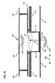
- Fig. 10 is a cross-sectional view cut along a longitudinal direction 520 of the railway car showing a roof structure equipped with an air conditioner disposed above the roof structure and said air conditioner.
- the air conditioner disposed above a roof structure 40 constituting the railway car has partitions disposed in the interior of a casing thereof to define an exterior blower chamber 102, an indoor blower chamber 104 and an equipment chamber 106.
- a heat insulating material 42 is applied on the inner side of the car of the roof structure 40, so as to prevent heat from the outer side of the car from entering the inner side of the car (especially in summer) and prevent heat from the inner side of the car from escaping to the outer side of the car (especially in winter).
- An opening is formed at a portion of the lower wall of the indoor blower chamber 104 facing the roof structure 40, and an opening 41 is formed on the roof structure 40 corresponding to said opening.
- An airtight packing is disposed around the opening 41 between the roof structure 40 and the air conditioner 100, so as to prevent rain water and dust from entering the car and separating outer air and air-conditioned air.
- a vertical ventilation duct 43 is disposed on the opening 41 between the roof structure 40 and the ceiling 47 of the car.
- a porous plate 48 and a filter 46 are layered in the named order from the side facing the cabin and disposed on the opening of the ceiling 47 connected to the ventilation duct 43.
- the porous plate 48 and the ceiling 47 substantially constitute an identical plane.
- An end in a height direction 530 (refer to Fig. 1 ) of the ventilation duct 43 is connected to the opening 41 formed on the roof structure 40.
- the air within the cabin passes through the porous plate 48 and the filter 46 and via the ventilation duct 43 to be introduced into the indoor blower chamber 104.
- an indoor blower and an indoor heat exchanger are disposed within the indoor blower chamber 104, and the temperature and humidity of the air guided from the cabin into the indoor blower chamber 104 is conditioned while passing through the indoor heat exchanger, and then re-supplied as conditioned air from the indoor blower chamber 104 into the cabin of the railway car.
- Patent document 1 teaches a railway car having an indoor blower of an air conditioner mounted in a space between the roof structure and the ceiling of the railway car and having cold air blown straight in the longitudinal direction of the car body, so that the ventilation resistance of the blowout section of the indoor blower is reduced to enhance the flow of cold air, and a small-sized air blower having an impeller whose outer diameter is smaller than that of a conventional impeller is used, by which the noise within the car can be reduced and power consumption of the indoor blower can be reduced.
- Japanese patent application laid-open publication No. 2007-253693 discloses an air conditioner for a vehicle and a railway car equipped therewith, wherein the air conditioner (body) mounted on the rooftop of a railway car has built therein indoor blowers for blowing air into the cabin and guide plates disposed under the blowers for changing the direction of flow of the air blown from the blowers, wherein the vibration generated when the air blown from the blowers collide against the guide plates is prevented frombeing directly transmitted to the car body, so as to suppress the vibration generated when the air blown from the blowers collide against the guide plates and reduce the vibration transmitted to the car body.
- the air conditioner body mounted on the rooftop of a railway car has built therein indoor blowers for blowing air into the cabin and guide plates disposed under the blowers for changing the direction of flow of the air blown from the blowers, wherein the vibration generated when the air blown from the blowers collide against the guide plates is prevented frombeing directly transmitted to the car body, so as to suppress the vibration generated when the air blown from the blowers collide against
- the noise within the cabin of the car is one of the causes that deteriorate the pleasantness of passengers. Therefore, the pleasantness of passengers may be deteriorated by the noise 310 generated by the air conditioner being transmitted to the cabin through the opening on the ceiling 47 of the cabin and diffused within the cabin as shown in Fig. 10 .
- the problem to be solved according to the present invention is to devise the arrangement of a ventilation duct connecting the rooftop equipment mounted on the roof structure of the railway car and the cabin, to thereby attenuate the noise entering the ventilation duct from the air conditioner in the process of traveling through the ventilation duct into the cabin.
- the present invention aims at solving the problems of the prior art by providing a railway car capable of maintaining the pleasantness of passengers by attenuating the noise entering the cabin of the railway car even when noise caused by the aerodynamic vibration of the air conditioner, especially the upper cover thereof, enters the ventilation duct.
- First and second aspects of the present invention provide railway cars according to claims 1 and 3.
- the noise transmitted through the first opening and the second openings into the cabin can be deadened within the cabin at equal distances from the openings due to mutual interference.
- the two second openings may not be aligned with the first opening in a height direction of the railway car, and can be offset in a longitudinal direction or a width direction of the railway car.
- a porous plate can be disposed on the second opening on a side facing the cabin, and a local aperture ratio of an area of the porous plate close to the first opening can be set low and a local aperture ratio of an area of the porous plate far from the first opening can be set high.
- the duct can have a sound absorbing function provided on the flow path side thereof, and the sound absorbing function can be provided by adopting at least one of the following arrangements: forming the panel member constituting the duct using a porous sound absorbing panel member; attaching a sound absorbing panel member to the panel member constituting the duct; and disposing a sound absorbing rectifying member on the panel member constituting the duct for smoothing the flow of air passing through the flow path.
- the duct constituting an expansion-chamber silencer or an interference silencer can be arranged so that one duct is disposed on a center in the width direction of the railway car or two ducts are disposed on either side in the width direction of the railway car.
- the present railway car arrangement can be applied to a ventilation unit having a ventilation function of the air within the cabin in place of the air conditioner, or to an air conditioner equipped with the ventilation function of the air within the cabin.
- the present invention can provide a railway car capable of overcoming the deterioration of pleasantness of passengers caused by the noise generated in the air conditioner, by adopting a ventilation duct connecting the roof structure having the air conditioner mounted thereon and the ceiling portion of the cabin constituting an interference silencer so that the noise passing therethrough is deadened via mutual interference within the cabin at equal distances from the openings.
- Fig. 1 is a perspective view showing a railway car equipped with an air conditioner .
- a width direction of a railway car (hereinafter simply referred to as "car") is denoted by number 510
- the longitudinal direction and the height direction of the car orthogonal to 510 are denoted by numbers 520 and 530.
- a car 1 is composed of an underframe 10 constituting a floor portion thereof, side structures 20 and 20 (only one of which is shown) erected from both ends in the width direction 510 of the underframe 10, end structures 30 and 30 (only one of which is shown) erected from both ends in the longitudinal direction 520 of the underframe 10, and a roof structure 40 mounted on the upper ends in the height direction 530 of the side structures 20 and 20 and the end structures 30 and 30.
- the underframe 10 In order to realize both lighter weight and improved productivity of the car, a method has been established to form the underframe 10, the side structures 20 and the roof structure 40 using hollow extruded shape members formed of aluminum alloy in which two opposing face plates are connected via ribs.
- a predetermined number of extruded shape members extruded and formed into a predetermined shape are arranged side by side along a direction orthogonal to the direction of extrusion on the upper surface of a rack.
- the extruded shape members are welded via friction stir welding or fusion welding along a weld line where the weld end surfaces are butted against each other, by which the underframe and various structures formed of a single panel are formed.
- Bogies 400 and 400 having multiple wheelsets supported rotatably on tracks are disposed on a lower side of the underframe 10 constituting the railway car 1 at both longitudinal ends, and the bogies 400 and 400 are connected to the underframe 10.
- Doors 24 enabling passengers to board and alight the railway car and windows 22 are disposed on the side structures 20 constituting the railway car 1.
- Air conditioners 100 and 100 are mounted on the upper side of the roof structure 40, which are secured to position via appropriate fixing means.
- Fig. 2 shows a first arrangement of a railway car, which is a cross-sectional view of the railway car cut at a perpendicular cross-section A along the longitudinal direction shown in Fig. 1 .
- the components and sections equivalent to those of the prior art car illustrated in Fig. 10 are denoted by the same reference numbers and detailed descriptions thereof are omitted.
- a ceiling member 47 defining a ceiling of a cabin (hereinafter simply referred to as "ceiling") is disposed on a lower side of the roof structure 40 facing the cabin at a distance from the roof structure 40.
- the roof structure 40 has an opening 41 as a first opening formed to enable air to flow to the air conditioner 100.
- an opening 47a as a second opening is disposed on the ceiling 47 enabling air from the cabin to pass therethrough.
- the opening 47a is disposed substantially immediately below the opening 41.
- a ventilation duct 43 is disposed between the roof structure 40 and the ceiling 47 so as to connect the opening 41 formed on the roof structure 40 and the opening 47a formed on the ceiling 47.
- the ventilation duct 43 connects the opening 41 and the opening 47a to constitute a flow path communicating the opening 41 and the opening 47a, so as to allow the air within the cabin to flow into the air conditioner 100.
- the ventilation duct 43 is formed so that the dimension thereof in the longitudinal direction 520 of the car is greater than the ventilation duct 43 illustrated in Fig. 10 .
- the ventilation duct 43 constitutes an expansion-chamber silencer.
- a filter 46 and a porous plate 48 are attached to the opening 47a of the ceiling 47.
- the opening 47a disposed on the ceiling 47 is not aligned with the opening 41 formed on the roof structure 40 in the height direction 530 of the car 1, and is formed at an offset position in the longitudinal direction 520.
- a panel member constituting the ventilation duct 43 and a panel member constituting the ceiling 47 are disposed immediately below the opening 41 of the roof structure 40.
- the panel member constituting the ventilation duct 43 is provided with a sound absorbing function by forming the panel member itself using porous members, or either in place of or in addition to this sound absorbing function, as shown in Fig. 2 , a sound absorbing member 45 is attached to the side facing the air flow path of the panel member constituting the ventilation duct 43 to enhance the sound deadening function of the ventilation duct 43.
- the air from the cabin is flown as shown by the arrow 300 through the opening 47a formed on the ceiling 47 equipped with the filter 46 and the porous plate 48 into the ventilation duct 43 and then flown in a bent manner toward the opening 41 formed on the roof structure 40.
- noise 310 When the car 1 is driven at high speed, noise 310 is generated by the aerodynamic vibration of an upper cover of the air conditioners caused by the air flow separation on the outer side of the air conditioners 100 disposed as rooftop equipments.
- Noise 310 normally travels through the opening 41 and the inner side of the ventilation duct 43 and passes through the opening 47a equipped with the filter 46 and the porous plate 48 into the cabin and is diffused (radiated) into the cabin.
- the noise 310 is emitted toward the cabin, the noise is prevented from directly travelling into the cabin by the ceiling 47 of the cabin disposed immediately below the opening 41 of the roof structure 40 and the bottom plate of the ventilation duct 43 disposed along the upper surface of the ceiling 47, and the noise is insulated.
- the expansion-chamber silencer formed by the ventilation duct 43 enables to reduce the noise level of the noise 310.
- the noise 310 is attenuated or absorbed while traveling within the ventilation duct 17 by the interference effect in which the direction of travel of the noise is bent and by the sound absorbing effect of the plate-shaped sound absorbing member 45 having a sound absorbing performance attached to the panel member constituting the ventilation duct 17, by which the noise level is reduced.
- the present arrangement is adopted in a railway car equipped with a rooftop equipment having a function to perform air conditioning of the air within the cabin, but the present arrangement can also be applied to a railway car having a ventilation duct connected to an opening for taking in air from the cabin to a ventilation unit for ventilating the air within the cabin or a ventilation unit chamber of an air conditioner having a ventilation unit built therein. Further, the present arrangement can be disposed on a cross-sectional position in a perpendicular plane extending in the longitudinal direction of the railway car in which the opening of the ceiling of the cabin is disposed at the center of the car. In this case, by arranging the opening of the roof structure 40 and the opening of the ceiling of the cabin to be displaced in the longitudinal direction of the car, the direction of travel of the noise traveling through the ventilation duct is bent.
- Fig. 9 shows an outline of the noise characteristics of the frequency and the sound pressure level within the cabin of the railway car according to the present invention.
- the sound pressure level can be reduced in the entire frequency band including a frequency f1 in which the sound pressure level is specifically high.
- a sound absorbing member (rectifying member) 45 having a triangular cross-section with an inclined plane is disposed so as not to block the air flow 300 within the ventilation duct 43 at a bent section (corner section) of the duct where stagnation or swirling of the air flow 300 is likely to occur.
- the sound absorbing member (rectifying member) 45 not only exerts a sound absorbing effect but also suppresses the increase of pressure loss of the ventilation duct 43.
- the air floe 300 within the ventilation duct 43 can be made smooth and the noise colliding against the ceiling 47 of the cabin can be absorbed.
- the sound absorbing member (rectifying member) 45 can also be disposed at a bent section at the opposing corner from the illustrated arrangement position of the sound absorbing member (rectifying member) 45 within the ventilation duct 43. Further, if the ventilation duct 43 alone enables to realize a sufficient noise reducing effect, the sound absorbing member (rectifying member) 45 can be omitted.
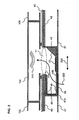
- Fig. 3 is a view showing a second arrangement of the railway car, which is a cross-sectional view taken at perpendicular cross-section A along the longitudinal direction of the railway car illustrated in Fig. 1 .
- the components equivalent to those in the arrangement shown in Fig. 2 are denoted by the same reference numbers and the detailed descriptions thereof are omitted.
- openings 44a and 44b are formed on the ventilation duct 43 corresponding to the opening 41 formed on the roof structure 40 and the opening 47a formed on the ceiling 47.
- the opening 41 of the roof structure 40, the openings 44a and 44b of the ventilation duct 43 and the opening 47a of the ceiling 47 are all formed along a substantially common center axis.
- the cross-sectional area 70 of the ventilation duct 43 perpendicular to the air flow 300 (horizontal plane) is greater than the area of the opening 44b of the ventilation duct 43, so that the ventilation duct 43 constitutes an expansion-chamber silencer.
- the transmission loss of the expansion-chamber silencer defined by the ventilation duct 43 is dominated by the ratio of the area of the opening 41 and the cross-sectional area 70, so that the cross-sectional area 70 of the ventilation duct 43 should be selected so that the transmission loss of the prominent frequency f that needs to be deadened becomes high.
- the spreading of the cavity of the ventilation duct 43 in the left and right (lateral) directions may be symmetric or asymmetric.
- a plate-like sound absorbing member 45 can be attached to the surface of the panel member forming the ventilation duct 43.
- the ventilation duct 43 having a cross-sectional area 70 selected so that the transmission loss of the peak frequency f1 of the noise becomes high enables to effectively attenuate the peak frequency f1 of the noise caused by the upper cover of the air conditioner 100, so that the noise level emitted into the cabin through the opening 47a of the ceiling 47 can be suppressed.
- the air flow 300 is substantially not bent in the ventilation duct 43, so that the pressure loss can be minimized compared to other embodiments. Therefore, the static pressure of the specification demanded in an indoor blower disposed in the interior of the air conditioner 100 can be reduced, so that the consumption power can be cut down and the noise level generated from the indoor blower itself can also be reduced.
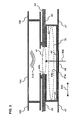
- Fig. 4 is a view showing a third arrangement of the railway car, showing a cross-sectional view in which the railway car shown in Fig. 1 is cut at a perpendicular cross-section A along the longitudinal direction.
- the components and sections equivalent to those in the structure illustrated in Fig. 2 are denoted by the same reference numbers and detailed descriptions thereof are omitted.
- the number of the opening 41 formed on the roof structure 40 is one but the opening on the ceiling 47 is divided into multiple parts.
- two openings 47a and 47a are disposed in dispersed manner along the longitudinal direction 520 of the car 1.
- the ventilation duct 43 also has openings 44a; 44b and 44b corresponding to these openings 47a and 47a formed thereto.
- a bottom panel is extended to the portion of the ventilation duct 43 opposed to the opening 41 formed on the roof structure 40, so that the opening 41 is not visible from immediately below the opening within the cabin.
- a sound absorbing member (rectifying member) 45 is disposed on the upper surface of a bottom panel at a branch point of the ventilation duct 43 opposed to the opening 41.
- the sound absorbing member (rectifying member) 45 has a substantially triangular cross-sectional shape and arranged so that both sides thereof constitute equally inclined planes.
- a filter 46 and a porous plate 48 are arranged respectively on the openings 47a and 47a of the ceiling 47 and the openings 44b and 44b of the ventilation duct 43.
- a plate-shaped sound absorbing member 45 can be adhered to the surface of a panel member of the ventilation duct 43 as shown in Fig. 2 .
- the air from the cabin enters through two openings 47a and 47a formed on the ceiling 47 and passes through the porous plates 48 and the filters 46 as air flows 300 and 300 into the ventilation duct 43.
- the air flows 300 and 300 in the ventilation duct 43 are guided smoothly via a triangular sound absorbing member (rectifying member) 45 so that the increase of pressure loss in the ventilation duct 43 is suppressed.
- the air flows 300 and 300 are converged near the opening 41 of the roof structure 40 to flow into the indoor blower chamber 104.
- the noise 310 generated in the indoor blower chamber 104 travels into the ventilation duct 43 through the opening 41 on the roof structure 40, but it is insulated by the panel member (bottom panel) constituting the ventilation duct 43.
- the noise 310 collides against the sound absorbing member 45 arranged on the air flow side of the panel member of the ventilation duct 43 and is absorbed or suppressed before being diffused into the cabin. Moreover, the noise 310 travels in a bent manner within the ventilation duct 43 and further attenuated, so that the traveling of noise into the cabin through the openings 47a and 47a on the ceiling 47 can even further be reduced.
- multiple openings 47a and 47a are disposed on the ceiling 47 of the cabin, so that the opening areas of the respective openings 47a formed on the ceiling 47 can be reduced to ensure an equivalent amount of air flow as the air flow 300 within the cabin flowing through the arrangement shown in Fig. 2 . Therefore, since the present arrangement enables to enhance the reflection of noise by the openings 47a formed on the ceiling 47, the noise within the cabin can be reduced even further than the arrangement of Fig. 2 . Further, the number of openings 47a disposed on the ceiling 47 can be three ormore. Furthermore, the sound absorbing member 45 can be omitted if sufficient noise reduction effect is achieved without the member.
- Fig. 5 illustrates a first embodiment of the railway car according to the present invention, showing a cross-sectional view in which the railway car shown in Fig. 1 is cut at a perpendicularcross-section A along thelongitudinaldirection.
- the components and sections equivalent to the structure illustrated in Fig. 2 are denoted by the same reference numbers and detailed descriptions thereof are omitted.
- Embodiment 1 illustrated in Fig. 5 has a basic arrangement similar to the arrangement of arrangement 3 shown in Fig. 4 , but the distances L1 and L2 from the center of the opening 41 formed on the roof structure 40 to the center of the openings 47a and 47a formed on the ceiling differ.
- the triangular sound absorbing member (rectifying member) 45 illustrated in Fig. 4 is not shown in Fig. 5 , but it can be disposed if necessary.
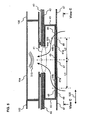
- Fig. 6 is a view illustrating embodiment 2 of the railway car according to the present invention, which is a cross-sectional view taken at perpendicular cross-section B along the width direction of the railway car shown in Fig. 1 .
- the components and sections equivalent to the structure illustrated in Fig. 2 are denoted by the same reference numbers and detailed descriptions thereof are omitted.
- heat exchangers 112 and 112 are arranged in separated manner along the width direction 510 of the car within the indoor blower chamber 104 constituting the air conditioner 100, and a blower 110 is disposed at the center in the width direction 510 between both heat exchangers 112 and 112.
- Ventilation ducts 43 (ducts are not shown in the drawing) adopting an arrangement in which openings are arranged in a dispersed manner similar to the ventilation duct 43 shown in Fig. 5 are disposed on left and right sides in the width direction 510 between the roof structure 40 and the ceiling 47 disposed on the inner side thereof.
- the ceiling 47 has openings 47a and 47a formed in a dispersed manner at positions separated from each other in the width direction 510.
- Each opening 47a has a filter 46 attached thereto.
- the openings 47a and 47a are arranged so that the distances from the center of the opening 41 of the roof structure 40 to the centers of openings 47a and 47a differ, as shown by L3 and L4.
- Openings 47b and 47b are disposed at the center in the width direction 510 of the ceiling 47.
- the conditioned air blown out of the blower 110 flows through the openings disposed at the center of width 510 of the roof structure 40 and is blown into the cabin through the openings 47b and 47b formed on the ceiling 47.
- an interference silencer is constituted, according to which the noise 310 generated in the indoor blower chamber 104 and emitted through openings 47a and 47a is deadened via interference within the cabin at equal distances from the openings 47a and 47a.
- the arrangement of the openings 47a on the ceiling 47 of the cabin can be determined arbitrary with respect to the lateral direction 510 and the longitudinal direction 520 of the car, and the number of openings 47a on the ceiling 47 can also be determined arbitrarily.
- the noises emitted through respective openings 47a and 47a on the ceiling 47 can be deadened via interference within the cabin at equal distances from the openings, according to which the noise having a prominent peak frequency can be reduced in the cabin and the pleasantness within the cabin can be improved.
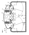
- Fig. 7 illustrates a third embodiment, of the railway car according to the present invention, showing a cross-sectional view in which the railway car shown in Fig. 1 is cut at a perpendicular cross-section B along the width direction of the railway car.
- the components and sections equivalent to those in the structure illustrated in Fig. 6 are denoted by the same reference numbers and detailed descriptions thereof are omitted.
- the ventilation duct arrangement disposed on left and right sides in the width direction 510 of the car is not illustrated, but as shown in Fig.
- the noise generated in the indoor blower chamber 104 of the air conditioner 100 is emitted into the cabin through the openings 47a and 47a arranged in a dispersed manner along the width direction 510 on the ceiling 47.
- the phases of noise 310 emitted through the openings 47a and 47a into the cabin are set so that the phases become opposite at positions close to the ears of standing passengers at substantially equal distances from the openings 47a and 47a (position at distance H1 from the floor surface of the underframe 10) and positions close to the ears of sitting passengers at predetermined distances from the openings 47a and 47a (position at distance H2 from the floor surface of the underframe 10).
- the phases of noises 310 emitted from openings 47a and 47a formed on the ceiling 47 are opposite, the noise at areas close to the ears of passengers sitting or standing in the cabin can be deadened via interference, according to which the noise having a prominent peak frequency can be reduced in the cabin and the pleasantness within the cabin can be improved.
- Fig. 8 shows a fourth embodiment of the railway car according to the present invention, which is a view of a ceiling of the cabin of the railway car seen from the direction of arrows C-C in Figs. 4 and 5 .
- the panel member of the ceiling 47 is disposed immediately below the opening 41 formed on the roof structure 40, and the area below the opening 41 is covered by the ceiling 47.
- porous plates 48 are fit to the openings 47a formed on the ceiling 47 of the cabin.
- the distances P1, P2, P3 ... between the pores 49 of the porous plate 48 are designed to become shorter as the distances from the opening 41 of the roof structure 40 to the pores 49 increase (inversely proportional).
- the interval is set short in the area where the distance from the opening 41 (sound source) is long (so that the aperture ratio of local porous plates 48 becomes high) and the interval is set long in the area where the distance from the opening is short (so that the aperture ratio of local porous plates 48 becomes small).
- the arrangement of the ventilation duct according to the present embodiment can be applied to arrangement 1 shown in Fig. 2 .
- the noise caused in the air conditioner 100 traveling through the ventilation duct 43 and emitted via the openings 49 of the porous plates 48 into the cabin can be attenuated both by the distance attenuation effect and the sound insulation effect of the porous plates 48, so that the noise level in the cabin can be reduced and the pleasantness within the cabin can be improved.
- the arrangement according to the present embodiment is adopted in a railway car having an air conditioner 100 disposed on the rooftop having a function to perform air conditioning of the air within the cabin, but the present arrangement can also be adopted in a railway car having an evacuation unit (ventilation unit) disposed on the rooftop for discharging the air within the cabin to the exterior.
- evacuation unit evacuation unit
- the opening disposed on the predetermined position on the roof structure 40 constituting the railway car 1 and the opening disposed on the ceiling within the cabin are connected via a ventilation duct, wherein the arrangements disclosed in arrangements 1 through 3 and embodiments 1, 2 and 4 can be adopted in the ventilation duct and the porous plates attached to the openings of the ceiling, according to which the noises caused by the upper cover of the evacuation unit traveling into the cabin can be suppressed.
Landscapes
- Engineering & Computer Science (AREA)
- Mechanical Engineering (AREA)
- Life Sciences & Earth Sciences (AREA)
- Wood Science & Technology (AREA)
- Air-Conditioning For Vehicles (AREA)
- Vehicle Interior And Exterior Ornaments, Soundproofing, And Insulation (AREA)
Claims (8)
- Eisenbahnwaggon (1), umfassend:eine Dachstruktur (40) mit einer an ihren oberen Teil angebrachten Klimaanlage (100) und mit einer ersten Öffnung (41), die ein Strömen von Luft zur Klimaanlage ermöglicht;ein Deckenelement, das an einer unteren Seite der Dachstruktur angeordnet ist, um eine Decke (47) einer Kabine zu definieren, und das zwei zweite Öffnungen (47a) aufweist, die ein Durchströmen von Luft aus der Kabine ermöglichen; undeinen Schacht (43), der die erste Öffnung (41) und die zweiten Öffnungen (47a) verbindet, um einen Strömungspfad zu bilden, der die erste Öffnung (41) und die zweiten Öffnungen (47a) verbindet;dadurch gekennzeichnet, dass eine Differenz zwischen einem Abstand (L1) in einer horizontalen Richtung von der ersten Öffnung (41) zu einer der zweiten Öffnungen (47a) und einem Abstand (L2) in einer horizontalen Richtung von der ersten Öffnung (41) zu der anderen zweiten Öffnung (47a) so eingestellt ist, dass sie im Wesentlichen einer Länge gleicht, bei der zu einem ganzzahligen Vielfachen einer Wellenlänge, die einer Spitzenfrequenz des von der Klimaanlage erzeugten Rauschens entspricht, eine halbe Wellenlänge davon hinzuaddiert wurde, sodass der Schacht einen Interferenzdämpfer bildet.
- Eisenbahnwaggon nach Anspruch 1, wobei die Klimaanlage mit einer Ablufteinheit ausgestattet ist, um die Luft innerhalb der Kabine nach außen abzugeben.
- Eisenbahnwaggon, umfassend:eine Dachstruktur, die eine Ablufteinheit, die an deren oberen Teil angeordnet ist, um Luft innerhalb einer Kabine nach außen abzugeben, und eine erste Öffnung (41) aufweist, die ein Strömen von Luft zur Ablufteinheit ermöglicht;ein Deckenelement, das an einer unteren Seite der Dachstruktur angeordnet ist, um eine Decke (47) der Kabine zu definieren, und das zwei zweite Öffnungen (47a) aufweist, die ein Eintreten von Luft aus der Kabine ermöglichen; undeinen Schacht (43), der die erste Öffnung (41) und die zweiten Öffnungen (47a) verbindet, um einen Strömungspfad zu erzeugen, der die erste Öffnung (41) und die zweiten Öffnungen (47a) verbindet;dadurch gekennzeichnet, dass eine Differenz zwischen einem Abstand in einer horizontalen Richtung von der ersten Öffnung (41) zu einer der zweiten Öffnungen (47a) und einem Abstand in einer horizontalen Richtung von der ersten Öffnung (41) zu der anderen zweiten Öffnung (47a) so eingestellt ist, dass sie im Wesentlichen einer Länge gleicht, bei der zu einem ganzzahligen Vielfachen einer Wellenlänge, die einer Spitzenfrequenz des von der Ablufteinheit erzeugten Rauschens entspricht, eine halbe Wellenlänge davon hinzuaddiert wurde, sodass der Schacht einen Interferenzdämpfer bildet.
- Eisenbahnwaggon nach einem der vorhergehenden Ansprüche, wobei,
um zu verhindern, dass in der Klimaanlage erzeugtes Rauschen direkt von der ersten Öffnung (41) zu den zweiten Öffnungen (47a) übertragen wird, ein den Schacht erzeugendes Paneelelement oder ein den Schacht erzeugendes Paneelelement, das auf ein Paneelelement geschichtet wird, das das auf der Kabinenseite angeordnete Dachelement erzeugt, im Wesentlichen direkt unterhalb der ersten Öffnung angeordnet ist. - Eisenbahnwaggon nach einem der vorhergehenden Ansprüche, wobei
die zwei zweiten Öffnungen (47a) nicht mit der ersten Öffnung (41a) in einer Höhenrichtung (530) des Eisenbahnwaggons fluchten und in einer Längsrichtung (520) oder einer Breitenrichtung (510) des Eisenbahnwaggons versetzt sind. - Eisenbahnwaggon nach einem der Ansprüche 1 bis 5, wobei
eine jeweilige poröse Platte (48) an einer der Kabine zugewandten Seite jeder zweiten Öffnung (47a) angeordnet ist; und
ein lokales Öffnungsverhältnis eines Bereichs jeder porösen Platte (48) nahe der ersten Öffnung (41) niedrig eingestellt ist und ein lokales Öffnungsverhältnis eines Bereichs der porösen Platte (48) fern der ersten Öffnung (41) hoch eingestellt ist. - Eisenbahnwaggon nach einem der Ansprüche 1 bis 6, wobei
der Schacht (43) eine geräuschabsorbierende Funktion aufweist, die an dessen Strömungspfadseite vorgesehen ist; und
die geräuschabsorbierende Funktion durch Übernehmen mindestens einer der nachfolgenden Anordnungen vorgesehen ist: Bilden des den Schacht erzeugenden Paneelelements unter Verwendung eines porösen geräuschabsorbierenden Paneelelements; Anbringen eines geräuschabsorbierenden Paneelelements an das den Schacht erzeugende Paneelelement; und Anordnen eines geräuschabsorbierenden Gleichrichtelements auf dem den Schacht erzeugenden Paneelelement zum Glätten der Luftströmung, die den Strömungspfad passiert. - Eisenbahnwaggon nach einem der Ansprüche 1 bis 7, wobei
der einen Interferenzdämpfer erzeugende Schacht (43) so angeordnet ist, dass ein Schacht mittig in der Breitenrichtung des Eisenbahnwaggons oder zwei Schächte an beiden Seiten in der Breitenrichtung des Eisenbahnwaggons angeordnet sind.
Applications Claiming Priority (1)
| Application Number | Priority Date | Filing Date | Title |
|---|---|---|---|
| JP2011004524A JP5643660B2 (ja) | 2011-01-13 | 2011-01-13 | 鉄道車両 |
Publications (2)
| Publication Number | Publication Date |
|---|---|
| EP2476599A1 EP2476599A1 (de) | 2012-07-18 |
| EP2476599B1 true EP2476599B1 (de) | 2013-06-12 |
Family
ID=44764022
Family Applications (1)
| Application Number | Title | Priority Date | Filing Date |
|---|---|---|---|
| EP20110250201 Not-in-force EP2476599B1 (de) | 2011-01-13 | 2011-02-22 | Eisenbahnwaggon |
Country Status (2)
| Country | Link |
|---|---|
| EP (1) | EP2476599B1 (de) |
| JP (1) | JP5643660B2 (de) |
Cited By (1)
| Publication number | Priority date | Publication date | Assignee | Title |
|---|---|---|---|---|
| RU2610753C1 (ru) * | 2015-12-07 | 2017-02-15 | Открытое акционерное общество "Тверской вагоностроительный завод" (ОАО "ТВЗ") | Система кондиционирования воздуха вагона |
Families Citing this family (14)
| Publication number | Priority date | Publication date | Assignee | Title |
|---|---|---|---|---|
| JP6395431B2 (ja) * | 2014-04-30 | 2018-09-26 | 三菱電機株式会社 | 車両用空気調和装置 |
| DE102014218442A1 (de) * | 2014-09-15 | 2016-03-17 | Siemens Aktiengesellschaft | Schienenfahrzeug mit einem Dachklimakanal |
| JP6500728B2 (ja) | 2014-11-27 | 2019-04-17 | 株式会社デンソー | 空調装置 |
| EP3225495B1 (de) * | 2014-11-28 | 2019-09-04 | Hitachi, Ltd. | Schienenfahrzeug mit anschlusskanal und verfahren zur befestigung des anschlusskanals |
| JP6616169B2 (ja) * | 2015-12-04 | 2019-12-04 | 株式会社日立製作所 | 内装パネルおよびこの内装パネルを備える鉄道車両 |
| CZ306749B6 (cs) * | 2016-04-22 | 2017-06-07 | Petr Morávek | Nástřešní vzduchotechnická jednotka s vestavěným tlumičem hluku |
| JP2017196912A (ja) * | 2016-04-25 | 2017-11-02 | 東日本旅客鉄道株式会社 | 車両用空調装置 |
| FR3096641A1 (fr) * | 2019-05-27 | 2020-12-04 | Alstom Transport Technologies | Dispositif de ventilation pour véhicule comportant au moins un élément d'absorption acoustique et véhicule associé |
| CN111361582B (zh) * | 2020-04-09 | 2021-03-26 | 中车株洲电力机车有限公司 | 一种轨道车辆用低噪音空调风道 |
| DE102020111834A1 (de) | 2020-04-30 | 2021-11-04 | Bombardier Transportation Gmbh | Schienenfahrzeugwagen mit einem Wagendach mit einem Flachdachbereich und einem Erhöhungsbereich |
| CN113928358A (zh) * | 2021-11-05 | 2022-01-14 | 中车株洲电力机车有限公司 | 一种轨道客车低噪声空调风道 |
| CN114261413B (zh) * | 2021-12-09 | 2023-04-07 | 中车株洲电力机车有限公司 | 一种有轨电车 |
| CN117360567B (zh) * | 2023-11-22 | 2025-11-21 | 中车南京浦镇车辆有限公司 | 一种适用于大面积照明的内顶板结构 |
| JP7651028B1 (ja) | 2024-02-08 | 2025-03-25 | 日本車輌製造株式会社 | 鉄道車両 |
Family Cites Families (14)
| Publication number | Priority date | Publication date | Assignee | Title |
|---|---|---|---|---|
| JPS57114086A (en) * | 1981-01-07 | 1982-07-15 | Japan National Railway | Silensor duct of air conditioner for vehicle |
| DE3224895A1 (de) * | 1982-07-03 | 1984-01-05 | Webasto-Werk W. Baier GmbH & Co, 8035 Gauting | Klimaanlage fuer kraftfahrzeuge |
| FR2600607B1 (fr) * | 1986-06-27 | 1990-04-13 | Alsthom | Dispositif de chauffage et de ventilation pour une voiture ferroviaire constituee de deux compartiments d'extremite a un seul etage et d'un compartiment central a deux etages |
| JPS6444375A (en) * | 1987-08-12 | 1989-02-16 | Hitachi Ltd | Air conditioner for vehicle |
| JPS6456269A (en) * | 1987-08-26 | 1989-03-03 | Hitachi Ltd | Structure for installation of airconditioner for vehicle |
| JPH0274459A (ja) * | 1988-09-09 | 1990-03-14 | Hitachi Ltd | 車両の暖房制御装置 |
| JPH0516803A (ja) * | 1991-07-08 | 1993-01-26 | Mitsubishi Electric Corp | 車両用空気調和装置 |
| AU669295B2 (en) * | 1994-07-12 | 1996-05-30 | Fiat Ferroviaria Spa | Air conditioning duct for railway vehicles |
| JP3462147B2 (ja) * | 2000-05-17 | 2003-11-05 | 川崎重工業株式会社 | 鉄道車両における空調ダクトの配設構造 |
| JP2002347617A (ja) * | 2001-05-24 | 2002-12-04 | Hitachi Ltd | 鉄道車両 |
| JP4286258B2 (ja) * | 2005-03-17 | 2009-06-24 | 株式会社日立製作所 | 軌条車両 |
| JP2007253693A (ja) * | 2006-03-22 | 2007-10-04 | Mitsubishi Electric Corp | 車両用空調装置及びそれを搭載した鉄道車両 |
| JP2010241257A (ja) * | 2009-04-06 | 2010-10-28 | Ihi Corp | 空気吹出装置 |
| JP5679796B2 (ja) * | 2010-12-17 | 2015-03-04 | 三菱電機株式会社 | 磁気フィルタを使用した車両用空気調和装置 |
-
2011
- 2011-01-13 JP JP2011004524A patent/JP5643660B2/ja active Active
- 2011-02-22 EP EP20110250201 patent/EP2476599B1/de not_active Not-in-force
Cited By (1)
| Publication number | Priority date | Publication date | Assignee | Title |
|---|---|---|---|---|
| RU2610753C1 (ru) * | 2015-12-07 | 2017-02-15 | Открытое акционерное общество "Тверской вагоностроительный завод" (ОАО "ТВЗ") | Система кондиционирования воздуха вагона |
Also Published As
| Publication number | Publication date |
|---|---|
| JP5643660B2 (ja) | 2014-12-17 |
| JP2012144167A (ja) | 2012-08-02 |
| EP2476599A1 (de) | 2012-07-18 |
Similar Documents
| Publication | Publication Date | Title |
|---|---|---|
| EP2476599A1 (de) | Eisenbahnwaggon | |
| US10556602B2 (en) | Car air conditioning duct and railcar | |
| US8869547B2 (en) | Air conditioner of track system vehicle | |
| JP6694329B2 (ja) | 鉄道車両用空調ダクト | |
| JP4531598B2 (ja) | 鉄道車両 | |
| CA2946129C (en) | Discharge plenum for packaged hvac unit | |
| CN104859674A (zh) | 一种消音风道及轨道车辆 | |
| JP7274923B2 (ja) | 車両用空調装置 | |
| JP7093328B2 (ja) | 鉄道車両の空調ダクトの製造方法 | |
| CN104875764A (zh) | 一种消音风道及轨道车辆 | |
| JP2001322544A (ja) | 鉄道車両における空調ダクトの配設構造 | |
| CN217864135U (zh) | 一种空调系统用消音风道及轨道车辆 | |
| JP2023014863A (ja) | 鉄道車両 | |
| KR20050105670A (ko) | 철도차량의 에어컨덕트 소음기 | |
| JP5474028B2 (ja) | 空調設備及び車両 | |
| JP4913672B2 (ja) | 鉄道車両の天井構造 | |
| TW202212183A (zh) | 軌道車輛 | |
| JP7551569B2 (ja) | 鉄道車両 | |
| US20250060127A1 (en) | Noise damper, in particular for an air conditioning system of a railway vehicle | |
| JP2025072887A (ja) | 軌条車両 | |
| US20240400118A1 (en) | Rail Vehicle and Manufacturing Method for Rail Vehicle | |
| JPWO2020170346A1 (ja) | 軌条車両 | |
| JP2012086587A (ja) | 鉄道車両 | |
| KR200149102Y1 (ko) | 소음방지장치가 구비된 철도차량용 에어 덕트 | |
| JP2024166878A (ja) | 軌条車両 |
Legal Events
| Date | Code | Title | Description |
|---|---|---|---|
| PUAI | Public reference made under article 153(3) epc to a published international application that has entered the european phase |
Free format text: ORIGINAL CODE: 0009012 |
|
| 17P | Request for examination filed |
Effective date: 20110310 |
|
| AK | Designated contracting states |
Kind code of ref document: A1 Designated state(s): AL AT BE BG CH CY CZ DE DK EE ES FI FR GB GR HR HU IE IS IT LI LT LU LV MC MK MT NL NO PL PT RO RS SE SI SK SM TR |
|
| AX | Request for extension of the european patent |
Extension state: BA ME |
|
| GRAP | Despatch of communication of intention to grant a patent |
Free format text: ORIGINAL CODE: EPIDOSNIGR1 |
|
| GRAS | Grant fee paid |
Free format text: ORIGINAL CODE: EPIDOSNIGR3 |
|
| GRAA | (expected) grant |
Free format text: ORIGINAL CODE: 0009210 |
|
| AK | Designated contracting states |
Kind code of ref document: B1 Designated state(s): AL AT BE BG CH CY CZ DE DK EE ES FI FR GB GR HR HU IE IS IT LI LT LU LV MC MK MT NL NO PL PT RO RS SE SI SK SM TR |
|
| REG | Reference to a national code |
Ref country code: GB Ref legal event code: FG4D |
|
| REG | Reference to a national code |
Ref country code: CH Ref legal event code: EP |
|
| REG | Reference to a national code |
Ref country code: AT Ref legal event code: REF Ref document number: 616575 Country of ref document: AT Kind code of ref document: T Effective date: 20130615 |
|
| REG | Reference to a national code |
Ref country code: IE Ref legal event code: FG4D |
|
| REG | Reference to a national code |
Ref country code: DE Ref legal event code: R096 Ref document number: 602011002011 Country of ref document: DE Effective date: 20130808 |
|
| PG25 | Lapsed in a contracting state [announced via postgrant information from national office to epo] |
Ref country code: GR Free format text: LAPSE BECAUSE OF FAILURE TO SUBMIT A TRANSLATION OF THE DESCRIPTION OR TO PAY THE FEE WITHIN THE PRESCRIBED TIME-LIMIT Effective date: 20130913 Ref country code: FI Free format text: LAPSE BECAUSE OF FAILURE TO SUBMIT A TRANSLATION OF THE DESCRIPTION OR TO PAY THE FEE WITHIN THE PRESCRIBED TIME-LIMIT Effective date: 20130612 Ref country code: LT Free format text: LAPSE BECAUSE OF FAILURE TO SUBMIT A TRANSLATION OF THE DESCRIPTION OR TO PAY THE FEE WITHIN THE PRESCRIBED TIME-LIMIT Effective date: 20130612 Ref country code: ES Free format text: LAPSE BECAUSE OF FAILURE TO SUBMIT A TRANSLATION OF THE DESCRIPTION OR TO PAY THE FEE WITHIN THE PRESCRIBED TIME-LIMIT Effective date: 20130923 Ref country code: SI Free format text: LAPSE BECAUSE OF FAILURE TO SUBMIT A TRANSLATION OF THE DESCRIPTION OR TO PAY THE FEE WITHIN THE PRESCRIBED TIME-LIMIT Effective date: 20130612 Ref country code: SE Free format text: LAPSE BECAUSE OF FAILURE TO SUBMIT A TRANSLATION OF THE DESCRIPTION OR TO PAY THE FEE WITHIN THE PRESCRIBED TIME-LIMIT Effective date: 20130612 Ref country code: NO Free format text: LAPSE BECAUSE OF FAILURE TO SUBMIT A TRANSLATION OF THE DESCRIPTION OR TO PAY THE FEE WITHIN THE PRESCRIBED TIME-LIMIT Effective date: 20130912 |
|
| REG | Reference to a national code |
Ref country code: AT Ref legal event code: MK05 Ref document number: 616575 Country of ref document: AT Kind code of ref document: T Effective date: 20130612 |
|
| REG | Reference to a national code |
Ref country code: NL Ref legal event code: VDEP Effective date: 20130612 |
|
| REG | Reference to a national code |
Ref country code: LT Ref legal event code: MG4D |
|
| PG25 | Lapsed in a contracting state [announced via postgrant information from national office to epo] |
Ref country code: BG Free format text: LAPSE BECAUSE OF FAILURE TO SUBMIT A TRANSLATION OF THE DESCRIPTION OR TO PAY THE FEE WITHIN THE PRESCRIBED TIME-LIMIT Effective date: 20130912 Ref country code: HR Free format text: LAPSE BECAUSE OF FAILURE TO SUBMIT A TRANSLATION OF THE DESCRIPTION OR TO PAY THE FEE WITHIN THE PRESCRIBED TIME-LIMIT Effective date: 20130612 Ref country code: RS Free format text: LAPSE BECAUSE OF FAILURE TO SUBMIT A TRANSLATION OF THE DESCRIPTION OR TO PAY THE FEE WITHIN THE PRESCRIBED TIME-LIMIT Effective date: 20130612 |
|
| PG25 | Lapsed in a contracting state [announced via postgrant information from national office to epo] |
Ref country code: LV Free format text: LAPSE BECAUSE OF FAILURE TO SUBMIT A TRANSLATION OF THE DESCRIPTION OR TO PAY THE FEE WITHIN THE PRESCRIBED TIME-LIMIT Effective date: 20130612 |
|
| PG25 | Lapsed in a contracting state [announced via postgrant information from national office to epo] |
Ref country code: EE Free format text: LAPSE BECAUSE OF FAILURE TO SUBMIT A TRANSLATION OF THE DESCRIPTION OR TO PAY THE FEE WITHIN THE PRESCRIBED TIME-LIMIT Effective date: 20130612 Ref country code: SK Free format text: LAPSE BECAUSE OF FAILURE TO SUBMIT A TRANSLATION OF THE DESCRIPTION OR TO PAY THE FEE WITHIN THE PRESCRIBED TIME-LIMIT Effective date: 20130612 Ref country code: BE Free format text: LAPSE BECAUSE OF FAILURE TO SUBMIT A TRANSLATION OF THE DESCRIPTION OR TO PAY THE FEE WITHIN THE PRESCRIBED TIME-LIMIT Effective date: 20130612 Ref country code: AT Free format text: LAPSE BECAUSE OF FAILURE TO SUBMIT A TRANSLATION OF THE DESCRIPTION OR TO PAY THE FEE WITHIN THE PRESCRIBED TIME-LIMIT Effective date: 20130612 Ref country code: PT Free format text: LAPSE BECAUSE OF FAILURE TO SUBMIT A TRANSLATION OF THE DESCRIPTION OR TO PAY THE FEE WITHIN THE PRESCRIBED TIME-LIMIT Effective date: 20131014 Ref country code: CZ Free format text: LAPSE BECAUSE OF FAILURE TO SUBMIT A TRANSLATION OF THE DESCRIPTION OR TO PAY THE FEE WITHIN THE PRESCRIBED TIME-LIMIT Effective date: 20130612 Ref country code: IS Free format text: LAPSE BECAUSE OF FAILURE TO SUBMIT A TRANSLATION OF THE DESCRIPTION OR TO PAY THE FEE WITHIN THE PRESCRIBED TIME-LIMIT Effective date: 20131012 |
|
| PG25 | Lapsed in a contracting state [announced via postgrant information from national office to epo] |
Ref country code: NL Free format text: LAPSE BECAUSE OF FAILURE TO SUBMIT A TRANSLATION OF THE DESCRIPTION OR TO PAY THE FEE WITHIN THE PRESCRIBED TIME-LIMIT Effective date: 20130612 Ref country code: RO Free format text: LAPSE BECAUSE OF FAILURE TO SUBMIT A TRANSLATION OF THE DESCRIPTION OR TO PAY THE FEE WITHIN THE PRESCRIBED TIME-LIMIT Effective date: 20130612 Ref country code: PL Free format text: LAPSE BECAUSE OF FAILURE TO SUBMIT A TRANSLATION OF THE DESCRIPTION OR TO PAY THE FEE WITHIN THE PRESCRIBED TIME-LIMIT Effective date: 20130612 |
|
| PLBE | No opposition filed within time limit |
Free format text: ORIGINAL CODE: 0009261 |
|
| STAA | Information on the status of an ep patent application or granted ep patent |
Free format text: STATUS: NO OPPOSITION FILED WITHIN TIME LIMIT |
|
| PG25 | Lapsed in a contracting state [announced via postgrant information from national office to epo] |
Ref country code: DK Free format text: LAPSE BECAUSE OF FAILURE TO SUBMIT A TRANSLATION OF THE DESCRIPTION OR TO PAY THE FEE WITHIN THE PRESCRIBED TIME-LIMIT Effective date: 20130612 |
|
| 26N | No opposition filed |
Effective date: 20140313 |
|
| PG25 | Lapsed in a contracting state [announced via postgrant information from national office to epo] |
Ref country code: IT Free format text: LAPSE BECAUSE OF FAILURE TO SUBMIT A TRANSLATION OF THE DESCRIPTION OR TO PAY THE FEE WITHIN THE PRESCRIBED TIME-LIMIT Effective date: 20130612 |
|
| REG | Reference to a national code |
Ref country code: DE Ref legal event code: R097 Ref document number: 602011002011 Country of ref document: DE Effective date: 20140313 |
|
| PG25 | Lapsed in a contracting state [announced via postgrant information from national office to epo] |
Ref country code: LU Free format text: LAPSE BECAUSE OF FAILURE TO SUBMIT A TRANSLATION OF THE DESCRIPTION OR TO PAY THE FEE WITHIN THE PRESCRIBED TIME-LIMIT Effective date: 20140222 Ref country code: MC Free format text: LAPSE BECAUSE OF FAILURE TO SUBMIT A TRANSLATION OF THE DESCRIPTION OR TO PAY THE FEE WITHIN THE PRESCRIBED TIME-LIMIT Effective date: 20130612 |
|
| REG | Reference to a national code |
Ref country code: CH Ref legal event code: PL |
|
| PG25 | Lapsed in a contracting state [announced via postgrant information from national office to epo] |
Ref country code: CH Free format text: LAPSE BECAUSE OF NON-PAYMENT OF DUE FEES Effective date: 20140228 Ref country code: LI Free format text: LAPSE BECAUSE OF NON-PAYMENT OF DUE FEES Effective date: 20140228 |
|
| REG | Reference to a national code |
Ref country code: FR Ref legal event code: ST Effective date: 20141031 |
|
| REG | Reference to a national code |
Ref country code: IE Ref legal event code: MM4A |
|
| PG25 | Lapsed in a contracting state [announced via postgrant information from national office to epo] |
Ref country code: IE Free format text: LAPSE BECAUSE OF NON-PAYMENT OF DUE FEES Effective date: 20140222 Ref country code: FR Free format text: LAPSE BECAUSE OF NON-PAYMENT OF DUE FEES Effective date: 20140228 |
|
| PG25 | Lapsed in a contracting state [announced via postgrant information from national office to epo] |
Ref country code: MT Free format text: LAPSE BECAUSE OF FAILURE TO SUBMIT A TRANSLATION OF THE DESCRIPTION OR TO PAY THE FEE WITHIN THE PRESCRIBED TIME-LIMIT Effective date: 20130612 |
|
| PG25 | Lapsed in a contracting state [announced via postgrant information from national office to epo] |
Ref country code: SM Free format text: LAPSE BECAUSE OF FAILURE TO SUBMIT A TRANSLATION OF THE DESCRIPTION OR TO PAY THE FEE WITHIN THE PRESCRIBED TIME-LIMIT Effective date: 20130612 |
|
| PG25 | Lapsed in a contracting state [announced via postgrant information from national office to epo] |
Ref country code: CY Free format text: LAPSE BECAUSE OF FAILURE TO SUBMIT A TRANSLATION OF THE DESCRIPTION OR TO PAY THE FEE WITHIN THE PRESCRIBED TIME-LIMIT Effective date: 20130612 |
|
| PG25 | Lapsed in a contracting state [announced via postgrant information from national office to epo] |
Ref country code: HU Free format text: LAPSE BECAUSE OF FAILURE TO SUBMIT A TRANSLATION OF THE DESCRIPTION OR TO PAY THE FEE WITHIN THE PRESCRIBED TIME-LIMIT; INVALID AB INITIO Effective date: 20110222 Ref country code: TR Free format text: LAPSE BECAUSE OF FAILURE TO SUBMIT A TRANSLATION OF THE DESCRIPTION OR TO PAY THE FEE WITHIN THE PRESCRIBED TIME-LIMIT Effective date: 20130612 |
|
| PG25 | Lapsed in a contracting state [announced via postgrant information from national office to epo] |
Ref country code: MK Free format text: LAPSE BECAUSE OF FAILURE TO SUBMIT A TRANSLATION OF THE DESCRIPTION OR TO PAY THE FEE WITHIN THE PRESCRIBED TIME-LIMIT Effective date: 20130612 |
|
| PG25 | Lapsed in a contracting state [announced via postgrant information from national office to epo] |
Ref country code: AL Free format text: LAPSE BECAUSE OF FAILURE TO SUBMIT A TRANSLATION OF THE DESCRIPTION OR TO PAY THE FEE WITHIN THE PRESCRIBED TIME-LIMIT Effective date: 20130612 |
|
| REG | Reference to a national code |
Ref country code: DE Ref legal event code: R082 Ref document number: 602011002011 Country of ref document: DE Representative=s name: MEWBURN ELLIS LLP, DE |
|
| PGFP | Annual fee paid to national office [announced via postgrant information from national office to epo] |
Ref country code: DE Payment date: 20221229 Year of fee payment: 13 |
|
| PGFP | Annual fee paid to national office [announced via postgrant information from national office to epo] |
Ref country code: GB Payment date: 20240109 Year of fee payment: 14 |
|
| REG | Reference to a national code |
Ref country code: DE Ref legal event code: R119 Ref document number: 602011002011 Country of ref document: DE |
|
| PG25 | Lapsed in a contracting state [announced via postgrant information from national office to epo] |
Ref country code: DE Free format text: LAPSE BECAUSE OF NON-PAYMENT OF DUE FEES Effective date: 20240903 |
|
| PG25 | Lapsed in a contracting state [announced via postgrant information from national office to epo] |
Ref country code: DE Free format text: LAPSE BECAUSE OF NON-PAYMENT OF DUE FEES Effective date: 20240903 |
|
| GBPC | Gb: european patent ceased through non-payment of renewal fee |
Effective date: 20250222 |
|
| PG25 | Lapsed in a contracting state [announced via postgrant information from national office to epo] |
Ref country code: GB Free format text: LAPSE BECAUSE OF NON-PAYMENT OF DUE FEES Effective date: 20250222 |