EP2472211A2 - Verteileinrichtung und Wärmetauschervorrichtung - Google Patents
Verteileinrichtung und Wärmetauschervorrichtung Download PDFInfo
- Publication number
- EP2472211A2 EP2472211A2 EP20110009614 EP11009614A EP2472211A2 EP 2472211 A2 EP2472211 A2 EP 2472211A2 EP 20110009614 EP20110009614 EP 20110009614 EP 11009614 A EP11009614 A EP 11009614A EP 2472211 A2 EP2472211 A2 EP 2472211A2
- Authority
- EP
- European Patent Office
- Prior art keywords
- fluid
- heat exchanger
- distribution
- container
- distributor
- Prior art date
- Legal status (The legal status is an assumption and is not a legal conclusion. Google has not performed a legal analysis and makes no representation as to the accuracy of the status listed.)
- Granted
Links
- 239000012530 fluid Substances 0.000 claims abstract description 84
- 229910052782 aluminium Inorganic materials 0.000 claims description 3
- XAGFODPZIPBFFR-UHFFFAOYSA-N aluminium Chemical compound [Al] XAGFODPZIPBFFR-UHFFFAOYSA-N 0.000 claims description 3
- 229910001220 stainless steel Inorganic materials 0.000 claims description 3
- 239000010935 stainless steel Substances 0.000 claims description 3
- 239000007788 liquid Substances 0.000 description 14
- 239000003507 refrigerant Substances 0.000 description 12
- 239000007789 gas Substances 0.000 description 11
- 239000002826 coolant Substances 0.000 description 6
- 238000000926 separation method Methods 0.000 description 6
- 239000000463 material Substances 0.000 description 4
- 238000001704 evaporation Methods 0.000 description 3
- 230000008020 evaporation Effects 0.000 description 3
- 230000002349 favourable effect Effects 0.000 description 3
- 239000000203 mixture Substances 0.000 description 3
- 230000001133 acceleration Effects 0.000 description 2
- 239000007791 liquid phase Substances 0.000 description 2
- VNWKTOKETHGBQD-UHFFFAOYSA-N methane Chemical compound C VNWKTOKETHGBQD-UHFFFAOYSA-N 0.000 description 2
- 238000010276 construction Methods 0.000 description 1
- 239000012809 cooling fluid Substances 0.000 description 1
- 230000001419 dependent effect Effects 0.000 description 1
- 230000005484 gravity Effects 0.000 description 1
- 238000011835 investigation Methods 0.000 description 1
- 229910052751 metal Inorganic materials 0.000 description 1
- 239000002184 metal Substances 0.000 description 1
- 238000000034 method Methods 0.000 description 1
- 238000010327 methods by industry Methods 0.000 description 1
- 239000003345 natural gas Substances 0.000 description 1
- 239000012071 phase Substances 0.000 description 1
- 238000011144 upstream manufacturing Methods 0.000 description 1
Images

Classifications
-
- F—MECHANICAL ENGINEERING; LIGHTING; HEATING; WEAPONS; BLASTING
- F28—HEAT EXCHANGE IN GENERAL
- F28F—DETAILS OF HEAT-EXCHANGE AND HEAT-TRANSFER APPARATUS, OF GENERAL APPLICATION
- F28F9/00—Casings; Header boxes; Auxiliary supports for elements; Auxiliary members within casings
- F28F9/02—Header boxes; End plates
- F28F9/026—Header boxes; End plates with static flow control means, e.g. with means for uniformly distributing heat exchange media into conduits
-
- F—MECHANICAL ENGINEERING; LIGHTING; HEATING; WEAPONS; BLASTING
- F28—HEAT EXCHANGE IN GENERAL
- F28D—HEAT-EXCHANGE APPARATUS, NOT PROVIDED FOR IN ANOTHER SUBCLASS, IN WHICH THE HEAT-EXCHANGE MEDIA DO NOT COME INTO DIRECT CONTACT
- F28D3/00—Heat-exchange apparatus having stationary conduit assemblies for one heat-exchange medium only, the media being in contact with different sides of the conduit wall, in which the other heat-exchange medium flows in a continuous film, or trickles freely, over the conduits
- F28D3/04—Distributing arrangements
-
- F—MECHANICAL ENGINEERING; LIGHTING; HEATING; WEAPONS; BLASTING
- F28—HEAT EXCHANGE IN GENERAL
- F28F—DETAILS OF HEAT-EXCHANGE AND HEAT-TRANSFER APPARATUS, OF GENERAL APPLICATION
- F28F9/00—Casings; Header boxes; Auxiliary supports for elements; Auxiliary members within casings
- F28F9/02—Header boxes; End plates
- F28F9/026—Header boxes; End plates with static flow control means, e.g. with means for uniformly distributing heat exchange media into conduits
- F28F9/0265—Header boxes; End plates with static flow control means, e.g. with means for uniformly distributing heat exchange media into conduits by using guiding means or impingement means inside the header box
-
- Y—GENERAL TAGGING OF NEW TECHNOLOGICAL DEVELOPMENTS; GENERAL TAGGING OF CROSS-SECTIONAL TECHNOLOGIES SPANNING OVER SEVERAL SECTIONS OF THE IPC; TECHNICAL SUBJECTS COVERED BY FORMER USPC CROSS-REFERENCE ART COLLECTIONS [XRACs] AND DIGESTS
- Y10—TECHNICAL SUBJECTS COVERED BY FORMER USPC
- Y10T—TECHNICAL SUBJECTS COVERED BY FORMER US CLASSIFICATION
- Y10T137/00—Fluid handling
- Y10T137/8593—Systems
Definitions
- the present invention relates to a distribution device for distributing a fluid, which in particular has a liquid fraction and a gas fraction. Furthermore, the invention relates to a heat exchanger device with a corresponding distributor.
- Distribution devices are known, for example, as inlet distributors when two or more phase fluids are introduced into a container.
- vane inlet devices are known in order to achieve an even distribution and improved pre-separation of the fluid.
- the DE 10 2009 022 673 A1 discloses, for example, arranged on a floor panel vanes in the manner of slats with lugs as a distributor.
- the DE 39 13 579 A1 discloses, for example, a heat exchanger with a jacket space through continuous tubes in which the medium to be cooled flows.
- a baffle plate is proposed. The disclosed baffle is provided with holes and arranged in a horizontal plane in the flow space.
- a distributor for distributing a fluid in a container from a fluid inlet of the container.
- the distributor device has at least one guide plate with a guide section and a distributor section adjoining the guide section.
- the distribution section has areas with openings for the passage of the fluid.
- the distribution device can be laterally closed in such a fluid-tight manner that fluid can only pass downwards through the openings and is otherwise held by the distribution device.
- the fluid may in particular have a liquid fraction and a gas fraction.
- the fluid may be a refrigerant which enters a jacket space as a container as gas-liquid mixture.
- a corresponding fluid flows only locally in the region of a fluid inlet or inlet nozzle of the container, a particularly favorable homogeneous fluid distribution is achieved by the distributor, which can also be referred to as inlet flow diverter.
- the distribution device is particularly suitable for use in a cryogenic plant. Areas of application, however, include other process engineering systems in which heat exchangers are used. This may be the case, for example, in the context of gas liquefaction or air separation.
- the guide plate is designed as a bent sheet with a profile.
- the profile may be, for example, a circular section, a bent angle or an edge profile, for example in the manner of an L-angle.
- the guide section and the distributor section are formed by at least two guide plates arranged one against the other and substantially perpendicular to one another.
- the guide plates may for example have a rectangular shape.
- the distribution plate has openings, such as holes, gaps, slits, or, for example, material removal machined recesses with different geometries, in particular to pass fluid downwardly.
- the distribution device is arranged horizontally.
- the distribution section forms, for example, a horizontal area with holes or slot openings.
- an embodiment of the distribution device for distributing a fluid in a container from a fluid inlet of the container comprises at least two guide plates arranged one against the other and substantially perpendicular to one another.
- one of the guide plates on areas with openings for the passage of the fluid.
- the first guide plate may in particular be designed as a baffle plate and the second guide plate as a distribution plate.
- the designed as baffle guide plate preferably extends vertically and running as a distribution plate baffle horizontal.
- the distributor is laterally vertically completely or partially closed, so that a fluid flow is passed through the openings of the Verteilblechs substantially.
- the two guide plates form an L-profile, and on end faces of the L-profile side plates are arranged.
- the Side plates for example, close off the distributor laterally fluid-tight.
- the openings are designed as slots.
- the slots are formed in particular in the distribution plate and in the direction substantially perpendicular to an edge of the distributor plate or a profile angle.
- the distributor is preferably formed at least partially of aluminum or stainless steel.
- the choice of material can be adapted to the particular use of the distribution device, for example in cryogenic plants.
- thermoelectric device with a container which has a fluid inlet, at least one heat exchanger block arranged in the container, and with a distributor arranged in the container above the heat exchanger block.
- the heat exchanger device is designed in particular as a block-in-container heat exchanger. This is also referred to as core-in-shell or block-in-kettle heat exchanger arrangements.
- several, usually designed as a plate heat exchanger heat exchanger blocks are arranged in a container or in a jacket space next to each other in the rule.
- the shell space forms, for example, a flow space for the cooling medium, which is usually evaporated isothermally, wherein the fluid flowing in the heat exchanger block is cooled.
- the heat exchanger blocks are preferably arranged at the same level. There may also be a non-isothermal evaporation.
- an embodiment of the heat exchanger device to a container with a fluid inlet, a plurality of arranged in the container Heat exchanger blocks and above the heat exchanger blocks, a distributor for distributing the fluid flowing through the fluid inlet, wherein the distributor comprises at least one guide plate having a guide portion and a distributor portion adjacent to the guide portion, and wherein the distribution portion having portions with openings for passage of the fluid.
- the container is cylindrical and forms a jacket space for a flow area for the refrigerant.
- the cylinder axis is preferably arranged horizontally.
- the distribution device is formed of a baffle plate, which is vertical, and a distribution plate which extends horizontally along or parallel to the cylinder axis.
- the downwardly directed openings in the distribution plate are above the heat exchanger blocks or the block. Above is understood to be higher than in a vertical direction.
- the distributor does not necessarily have to run completely over the heat exchanger blocks.
- the distributor device is arranged in the container in such a way that a fluid flowing into the container through the fluid inlet flows through the openings of the distributor section into predetermined jacket regions in a targeted manner.
- inflowing fluid at least partially falls on the heat exchanger block.
- the arrangement and design of the openings allows a targeted distribution of the liquid portion of the fluid through the openings on or adjacent to or the heat exchanger blocks in the shell space.
- the distributor fluid in particular liquid, is introduced or distributed in areas of the shell space, where possible little or no gas is generated by evaporation, for example by a heat exchanger block.
- the distributor fluid in particular liquid
- the distributor fluid is introduced or distributed in areas of the shell space, where possible little or no gas is generated by evaporation, for example by a heat exchanger block.
- the separation of a gas and liquid phase is thereby improved.
- the distribution device together with walls of the container and the optional side plates, delimits a space portion in the container.
- the distributor and walls of the container include a space portion.
- the space portion for example in the manner of a distribution channel, connects the fluid inlet in a wall of the container with the flow space by means of the openings in the distribution section of the distributor.
- the space portion is coupled upstream of the fluid inlet and outflow coupled to the openings as an outlet.
- the fluid inlet has an inlet cross-sectional area and an inlet direction.
- the distribution device preferably has a longitudinal axis, which is designed to be horizontal and parallel along the longitudinal extent of the container.
- the longitudinal extent of the distributor is perpendicular to the direction of entry.
- the openings are designed as slots perpendicular to a longitudinal axis of the container.
- the slots extend, for example, parallel to cross-sectional areas of the space portion or of the container, which are formed perpendicular to a longitudinal axis of the container.
- the cross section of a distribution channel formed by means of the distributor and walls of the container corresponds to an inlet cross section of the fluid inlet. This can be a particularly favorable Realize flow distribution, for example, from the fluid inlet to the left and right of a corresponding nozzle away.
- the distribution device is designed in the manner of an L-profile sheet.
- the slot width is between 30 mm and 70 mm. Most preferably, the slots are 50mm wide.
- the openings are made as slots, and the slots are spaced from an edge or angle of the L profile sheet between 40 mm and 100 mm. Particularly preferably, the distance between 60 mm and 80 mm.
- a total cross-sectional area of all openings is between 150% and 250% of the cross-sectional area of the fluid inlet. Particularly preferably, the total cross-sectional area of the openings is twice as large as the cross-sectional area of the inlet.
- the distributor is then preferably completed by side plates. In principle, several inlet ports are conceivable.
- the distribution section of the distribution device is configured with fluid-tight regions such that no heat exchanger block is below the fluid-tight region.
- the distribution section of the distribution device is provided with openings exclusively directly above the heat exchanger block (s) and is otherwise made fluid-tight. As a result, no fluid drips or flows into areas between adjacent heat exchanger blocks in the container.
- the heat exchanger blocks and the distribution device are arranged such that openings of the distribution section are present above the heat exchanger blocks and the distribution section is otherwise closed.
- the distribution section of the distribution device is provided with openings next to or between the heat exchanger blocks and otherwise configured fluid-tight. As a result, no fluid drips or flows into areas above the heat exchanger blocks in the container.
- the heat exchanger blocks and the distribution device are arranged such that openings of the distribution section are present alongside or laterally of the heat exchanger blocks and the distribution section is otherwise closed.
- one or more fluid outlets are provided in addition to a fluid inlet. Below the fluid outlet nozzle of the container, in particular for gaseous fluid, no openings of the distribution section of the distributor are provided.
- the fluid is distributed as a cooling medium from above via a horizontal distribution channel by means of the distributor to where there is a favorable flow around the heat exchanger blocks.
- the arrangement of the openings, the fluid can be selectively directed into areas of the flow area with the heat exchanger blocks, in which a gas-liquid separation is efficiently possible.
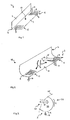
- the FIG. 1 shows a perspective schematic representation of a first embodiment of a distribution device.
- the distributor 1 comprises a vertical and a horizontal baffle which form an L-angle along a common edge 13.
- the vertical guide plate 2 serves as a guide section and the horizontal distribution plate 3 as a distribution section.
- the distribution plate 3 has areas 4, 5 with openings 8, 9. Between the areas 4, 5 with the openings 8, 9, a fluid-tight region 10 is provided. Through the openings, which in the FIG. 1 in the rear region 4 are designed as slots 8, and in the front region 5 are formed as holes 9, fluid can pass downwards.
- the distribution device 1 as in the FIG. 1 is shown, combines the functions of a perforated baffle plate with that of an inlet flow diverter, so a manifold near a flow nozzle of a container.
- the guide section 2 essentially serves to drain fluid or divert it.
- the distribution section 3 makes it possible, with the aid of the openings 8, 9, to dispense fluid specifically below the distribution device 1.
- the FIG. 2 shows a perspective schematic representation of a second embodiment of a distribution device.
- the distribution device 18 is designed in the manner of a curved guide plate.
- the FIG. 2 shows one in the orientation of the FIG. 2 vertical guide section 2 and a horizontal distribution section 3 of the baffle.
- In the distribution section 3 are provided areas 4, 5 with longitudinal openings 8 in the manner of slits.
- In the central region 10 of the distribution section 3 are no holes or slits.
- FIG. 2 is a possible fluid flow indicated by arrows.
- inflowing through an inlet connection of a container fluid 15 reaches the baffle of the distribution device 18.
- the fluid is pressed substantially horizontally to the left and right, as indicated by the arrows 16.
- the fluid flows or flows along the fluid-tight region 10 in the direction of the areas 4, 5 provided with openings 8.
- the fluid exits through the openings 8 downwards, which is indicated by arrows 17.
- FIG. 3 shows a schematic cross-sectional view of a third embodiment of a distribution device.
- the in the FIG. 3 distributor device 24 shown is manufactured as a circular segment-shaped profile, for example from a sheet metal such as aluminum or stainless steel.
- a distribution section 2 is provided opposite a container opening or a fluid inlet 26. Fluid 15 flowing in through the fluid inlet 26 strikes the distributor section 2 of the distributor device 24. In the lower region, downwardly directed openings are provided in the plate of the distributor device 24, which are shown dotted. The circular section, which points essentially downwards, is referred to as the distribution section 3. Due to the plate areas provided with openings in the areas 4, the fluid 17 can escape downwards.
- the arrangement and positioning of the openings within the distribution channel 23 can be a targeted supply of fluid, for example, in the direction of heat exchanger blocks.
- gravitational acceleration which is usually shown vertically. Horizontal in this context means perpendicular to the gravitational acceleration.
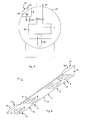
- FIG. 4 a heat exchanger device 100 shown in longitudinal section.
- FIG. 5 FIG. 3 illustrates a section AA transverse to an axis of symmetry of the heat exchanger device 100.
- FIG. 6 an illustration of a fourth embodiment of a distributor 101 is shown in perspective, which is provided in the heat exchanger device 100.
- the heat exchanger device 100 is configured as a block-in-tank configuration. That is, a plurality of heat exchanger blocks 28, 29, 30 are installed within a cylindrical container 27, which is also referred to as a jacket.
- a block-in-container arrangement which is also referred to as core-in-shell or block-in-kettle, is in particular that heat exchanger blocks in the form of plate heat exchangers can be used particularly efficiently.
- plate heat exchangers several layers of heat exchange passages are delimited by separating plates against each other, which usually leads to a cuboid block.
- FIG. 4 detects, in a cylindrical container 27 whose longitudinal axis 34, which is also an axis of symmetry and extends horizontally, three heat exchanger blocks 28, 29, 30 are provided.
- fluid to be liquefied such as natural gas or a process gas
- inlet ports 31 which pierce the jacket or tank 27 in an upper region
- outlet nozzle 32 which are provided in the lower region of the shell 27, is discharged.
- a mainly liquid refrigerant is usually isothermal evaporated.
- a fluid inlet 26 is provided approximately in the middle in the upper region in the jacket 27.
- the fluid is referred to below as a refrigerant or cryogen.
- the refrigerant occurs locally as a gas-liquid mixture.
- the liquid fraction is vaporized at the heat exchanger blocks 28, 29, 30 and exits as gas through fluid outlet openings 33 from the jacket space again.
- the fluid inlet 26 is arranged lower than the fluid outlets 33 for the cold medium. It is desirable that only the gas portion of the refrigerant from the shell space via the outlet nozzle or fluid outlets 23 is withdrawn. In order to reduce entrainment of liquid refrigerant as much as possible, an improved distribution of the entering through the fluid inlet nozzle 26 gas-liquid mixture is desired. Therefore, a distributor 101 is provided in the container 27.
- FIG. 5 In particular in the cross-sectional representation of FIG. 5 can be seen the circular cross-section of the cylinder jacket 27 as a container and provided in the interior heat exchanger block 28 with an inlet 31 and a drain 32 for fluid to be cooled. In the orientation of FIG. 5 is provided in the upper left circular segment of the fluid inlet 26.
- the refrigerant 15 enters a distribution channel 23 there.
- the distribution channel 23 is formed by a space portion within the shell 27, which is formed by the jacket wall 25 and an L-shaped guide plate of a guide portion and a distribution section 3.
- FIG. 6 shows a perspective view of an embodiment of the distributor 101.
- the FIG. 6 shows the distributor 101 with a baffle 2, which is provided vertically and a distribution plate 3, which is provided horizontally.
- side plates 19, 20 are provided, which are placed on the L-profile edges and connected fluid-tight and are connected to the guide and distribution plates 2, 3.
- An edge or contour 21, 22 of Side plates 19, 20 nestles against the container wall 25 (see. FIG. 5 ) and forms a fluid-tight seal with the container wall or jacket wall 25.
- the resulting space section or distribution channel 23 thus connects the fluid inlet 26 with the interior of the shell 27 via the openings 8 in the distribution plate 3.
- the openings 8 are slit-shaped and extend substantially perpendicular to a longitudinal extension of the distributor 101 and perpendicular to an axis of symmetry 34 of the container 27th
- FIGS. 4 . 5 and 6 One recognizes in conjunction with the FIGS. 4 . 5 and 6 in that fluid-tight regions 10, 11, 12 are provided in the distribution plate 3, where, on the one hand, there is no heat exchanger block 28, 29, 30 below the distribution plate 3 and, on the other hand, inlet or outlet ports 26, 33 are arranged above the distribution plate 3.
- the areas 4, 5, 6, 7 with openings 8 are provided substantially exclusively above but between the heat exchanger blocks 28, 29, 30. This ensures that a gas-liquid separation of the refrigerant medium takes place uniformly over the entire container length and liquid refrigerant medium does not flow directly onto the heat exchanger blocks 17 (arrows 17).
- the fluid inlet in the direction of the distributor 101 is arranged essentially in the middle of the longitudinal extent of the distributor 101. This results in a splitting of an inflowing fluid into two partial flows each about half.
- the inlet nozzle 26 has a predetermined inlet cross-section.
- the geometry and the dimensions of the distribution channel 23 by an L-profile is chosen such that the most uniform possible distribution of the cooling medium in the shell space is achieved.
- the geometry and the dimensions of the distribution channel 23 by an L-profile is chosen such that the most uniform possible distribution of the cooling medium in the shell space is achieved.
- gas loading of the fluid by evaporation of the coolant at the heat exchanger blocks 28, 29, 30 is particularly high, one can reduce the number of slots per length of the distribution plate 3 or slot cross-sections. As a result, the gas content is more manageable by introduced steam at the refrigerant inlet at the openings.
Landscapes
- Engineering & Computer Science (AREA)
- Physics & Mathematics (AREA)
- Thermal Sciences (AREA)
- Mechanical Engineering (AREA)
- General Engineering & Computer Science (AREA)
- Heat-Exchange Devices With Radiators And Conduit Assemblies (AREA)
- Details Of Heat-Exchange And Heat-Transfer (AREA)
- Steam Or Hot-Water Central Heating Systems (AREA)
Abstract
Description
- Die vorliegende Erfindung betrifft eine Verteileinrichtung zum Verteilen eines Fluids, welches insbesondere einen Flüssiganteil und einen Gasanteil aufweist. Ferner betrifft die Erfindung eine Wärmetauschervorrichtung mit einer entsprechenden Verteileinrichtung.
- Verteileinrichtungen sind beispielsweise als Eintrittsverteiler bekannt, wenn zwei oder mehrphasige Fluide in einen Behälter eingeleitet werden. Im Zusammenhang mit Gas-Flüssig-Abscheidebehältern sind zum Beispiel sogenannte Vane Inlet Devices bekannt, um eine Gleichverteilung und verbesserte Vorabscheidung des Fluids zu erzielen. Die
DE 10 2009 022 673 A1 offenbart beispielsweise an einem Bodenblech angeordnete Leitschaufeln in der Art von Lamellen mit Fangnasen als Verteileinrichtung. - Insbesondere in Wärmetauschern ist es wünschenswert, ein Kältemittel möglichst homogen in einem Mantelraum zu verteilen. Die
DE 39 13 579 A1 offenbart beispielsweise einen Wärmetauscher mit einen Mantelraum durchlaufenden Rohren, in denen das zu kühlende Medium fließt. Um in dem umgebenden Strömungsraum eine ausgehend von einem Eintrittsstutzen gleichmäßige Kühlmittelverteilung zu erzielen, ist ein Prallblech vorgeschlagen. Das offenbarte Prallblech ist mit Löchern versehen und in einer horizontalen Ebene in dem Strömungsraum angeordnet. - Es ist wünschenswert, beispielsweise bei Block-in-Behälter Konstruktionen von Wärmetauschern eine noch bessere Verteilung von Kühlfluid zu erzielen.
- Es ist eine Aufgabe der vorliegenden Erfindung eine verbesserte Verteilung von in einen Behälter einströmendes Fluid zu schaffen.
- Demgemäß wird eine Verteileinrichtung zum Verteilen eines Fluids in einem Behälter von einem Fluideintritt des Behälters aus vorgeschlagen. Dabei weist die Verteileinrichtung mindestens eine Leitplatte mit einem Leitabschnitt und einem an den Leitabschnitt angrenzenden Verteilabschnitt auf. Der Verteilabschnitt hat Bereiche mit Öffnungen zum Durchlassen des Fluids.
- Die Verteileinrichtung kann seitlich derart fluiddicht verschlossen sein, dass Fluid auschließlich durch die Öffnungen nach unten treten kann und ansonsten von der Verteileinrichtung gehalten wird.
- Das Fluid kann insbesondere einen Flüssiganteil und einen Gasanteil aufweisen. Beispielsweise kann das Fluid ein Kältemittel sein, welches als Gas-Flüssig-Gemisch in einen Mantelraum als Behälter eintritt.
- Da in der Regel ein entsprechendes Fluid nur lokal im Bereich eines Fluideintritts oder Eintrittsstutzens des Behälters einströmt, wird durch die Verteileinrichtung, die auch als Inlet Flow Diverter bezeichnet werden kann, eine besonders günstige homogene Fluidverteilung erreicht.
- Die Verteileinrichtung eignet sich insbesondere für den Einsatz in einer kryotechnischen Anlage. Einsatzgebiete umfassen jedoch auch andere prozesstechnische Anlagen, in denen Wärmetauscher Verwendung finden. Dies kann beispielsweise im Rahmen der Gasverflüssigung oder Luftzerlegung der Fall sein.
- Bei einer Ausführungsform der Verteileinrichtung ist die Leitplatte als gebogenes Blech mit einem Profil ausgeführt. Das Profil kann dabei zum Beispiel ein Kreisabschnitt sein, ein gebogener Winkel oder auch ein Kantenprofil, beispielsweise in der Art eines L-Winkels.
- In einer Ausführungsform der Verteileinrichtung sind der Leitabschnitt und der Verteilabschnitt von mindestens zwei aneinander und im Wesentlichen senkrecht zueinander angeordneten Leitplatten gebildet.
- Die Leitplatten können beispielsweise rechteckige Form haben.
- Die Verteilplatte hat Öffnungen, wie Löcher, Spalte, Schlitze oder zum Beispiel durch Materialabtrag erzeugte Ausnehmungen mit anderen Geometrien, um insbesondere Fluid in Richtung nach unten durchzulassen. Vorzugsweise ist die Verteileinrichtung horizontal angeordnet. Der Verteilabschnitt bildet zum Beispiel eine horizontale Fläche mit Löchern oder Schlitzöffnungen.
- Insofern umfasst eine Ausführungsform der Verteileinrichtung zum Verteilen eines Fluids in einem Behälter von einem Fluideintritt des Behälters aus, mindestens zwei aneinander und im Wesentlichen senkrecht zueinander angeordnete Leitplatten. Dabei weist eine der Leitplatten Bereiche mit Öffnungen zum Durchlassen des Fluids auf. Die erste Leitplatte kann insbesondere als Prallblech ausgebildet sein und die zweite Leitplatte als Verteilblech. Die als Prallblech ausgestaltete Leitplatte verläuft vorzugsweise vertikal und die als Verteilblech ausgeführte Leitplatte horizontal.
- Vorzugsweise ist die Verteileinrichtung seitlich vertikal ganz oder teilweise verschlossen, damit eine Fluidströmung im Wesentlichen durch die Öffnungen des Verteilblechs geleitet wird.
- Man kann die Leitplatten als ein gewinkeltes Blech materialeinstückig ausführen.
- Bei einer Ausführung der Verteileinrichtung bilden die beiden Leitplatten ein L-Profil aus, und auf Stirnseiten des L-Profils sind Seitenplatten angeordnet. Die Seitenplatten schließen zum Beispiel die Verteileinrichtung seitlich fluiddicht ab. Durch eine gewinkelte Ausführung, insbesondere mit Seitenplatten, ist es möglich, in einem Behälter einen Raumabschnitt zu begrenzen, der beispielsweise in der Art eines Verteilungskanals wirkt.
- Vorzugsweise sind die Öffnungen als Schlitze ausgeführt. Die Schlitze sind insbesondere in dem Verteilblech und in Richtung im Wesentlichen senkrecht zu einer Kante des Verteilblechs oder einem Profilwinkel ausgebildet.
- Die Verteileinrichtung ist vorzugsweise zumindest teilweise aus Aluminium oder Edelstahl gebildet. Die Materialwahl kann an die jeweilige Verwendung der Verteileinrichtung, beispielsweise in kryogenen Anlagen, angepasst werden.
- Es wird ferner eine Wärmetauschervorrichtung mit einem Behälter, welcher einen Fluideintritt aufweist, mindestens einem in dem Behälter angeordneten Wärmetauscherblock, und mit einer in dem Behälter oberhalb des Wärmetauscherblocks angeordneten Verteileinrichtung vorgeschlagen.
- Die Wärmetauschervorrichtung ist insbesondere als Block-in-Behälter-Wärmetauscher ausgeführt. Man spricht auch von Core-in-Shell oder Block-in-Kettle Wärmetauscheranordnungen. Dabei sind in der Regel mehrere, meist als Platten-Wärmetauscher ausgeführte Wärmetauscherblöcke in einem Behälter bzw. in einem Mantelraum nebeneinander angeordnet. Der Mantelraum bildet beispielsweise einen Strömungsraum für das Kühlmedium, welches meist isotherm verdampft wird, wobei das in dem Wärmetauscherblock strömende Fluid abgekühlt wird. Die Wärmetauscherblöcke sind bevorzugt auf demselben Niveau angeordnet. Es kann auch eine nicht isotherme Verdampfung erfolgen.
- Insofern weist eine Ausführungsform der Wärmetauschervorrichtung einen Behälter mit einem Fluideintritt auf, mehrere in dem Behälter angeordnete Wärmetauscherblöcke und oberhalb der Wärmetauscherblöcke eine Verteileinrichtung zum Verteilen des durch den Fluideintritt einströmenden Fluids, wobei die Verteileinrichtung mindestens eine Leitplatte mit einem Leitabschnitt und einem an den Leitabschnitt angrenzenden Verteilabschnitt umfasst, und wobei der Verteilabschnitt Bereiche mit Öffnungen zum Durchlassen des Fluids aufweist.
- Bei einer Ausführungsform ist der Behälter zylinderförmig ausgebildet und bildet einen Mantelraum für einen Strömungsbereich für das Kältemittel. Die Zylinderachse ist dabei vorzugsweise horizontal angeordnet.
- Bei einer bevorzugten Ausführungsform ist die Verteileinrichtung aus einem Prallblech, welches vertikal, und einem Verteilblech, welches horizontal entlang oder parallel zu der Zylinderachse verläuft, ausgebildet. Die nach unten gerichteten Öffnungen in dem Verteilblech liegen oberhalb der Wärmetauscherblöcke oder des Blockes. Oberhalb wird verstanden als in einer vertikalen Richtung höher liegend. Die Verteileinrichtung muss nicht zwingend vollständig über den Wärmetauscherblöcken verlaufen.
- Vorzugsweise ist bei der Wärmetauschervorrichtung die Verteileinrichtung derart in dem Behälter angeordnet, dass ein durch den Fluideintritt in den Behälter einströmendes Fluid durch die Öffnungen des Verteilabschnitts gezielt in vorgegebene Mantelbereiche einströmt. Beispielsweise fällt einströmendes Fluid zumindest teilweise auf den Wärmetauscherblock. Die Anordnung und Ausführung der Öffnungen erlaubt es, eine gezielte Verteilung des Flüssiganteils des Fluids durch die Öffnungen auf oder neben den oder die Wärmetauscherblöcke in dem Mantelraum.
- Vorzugsweise wird mit Hilfe der Verteileinrichtung Fluid, insbesondere Flüssigkeit, in Bereiche des Mantelraums eingeleitet oder verteilt, wo möglichst wenig oder kein Gas durch Verdampfen, beispielsweise durch einen Wärmetauscherblock, erzeugt wird. Die Trennung einer Gas- und Flüssigphase wird dadurch verbessert.
- Bei einer Ausführungsform der Wärmetauschervorrichtung begrenzt die Verteileinrichtung zusammen mit Wänden des Behälters und den optionalen Seitenplatten einen Raumabschnitt in dem Behälter. Die Verteileinrichtung und Wände des Behälters schließen beispielsweise einen Raumabschnitt ein. Der Raumabschnitt, beispielsweise in der Art eines Verteilerkanals, verbindet den Fluideintritt in einer Wand des Behälters mit dem Strömungsraum mit Hilfe der Öffnungen in dem Verteilabschnitt der Verteileinrichtung.
- Zum Beispiel ist der Raumabschnitt einströmseitig an den Fluideintritt gekoppelt und ausströmseitig an die Öffnungen als Austritt gekoppelt.
- Bei einer Ausführungsform der Wärmetauschervorrichtung hat der Fluideintritt eine Eintrittsquerschnittsfläche und eine Eintrittsrichtung. Die Verteileinrichtung hat vorzugsweise eine Längsachse, welche entlang der Längenausdehnung des Behälters horizontal und parallel ausgeführt ist.
- Vorzugsweise steht die Längenausdehnung der Verteileinrichtung senkrecht zur Eintrittsrichtung. In einer Ausführungsform sind die Öffnungen als Schlitze senkrecht zu einer Längsachse des Behälters ausgeführt. Die Schlitze verlaufen beispielsweise parallel zu Querschnittsflächen des Raumabschnitts oder des Behälters, welche senkrecht zu einer Längsachse des Behälters gebildet sind.
- Bei einer bevorzugten Ausführungsform der Wärmetauschervorrichtung entspricht der Querschnitt eines mit Hilfe der Verteileinrichtung und Wänden des Behälters gebildeten Verteilkanals einem Eintrittsquerschnitt des Fluideintritts. Dadurch lässt sich eine besonders günstige Mengenstromaufteilung beispielsweise von dem Fluideintritt nach links und rechts von einem entsprechenden Stutzen weg realisieren.
- In einer bevorzugten Ausführungsform ist die Verteileinrichtung in der Art eines L-Profilblechs ausgeführt. Vorzugsweise ist die Schlitzbreite zwischen 30 mm und 70 mm. Besonders bevorzugt sind die Schlitze 50 mm breit.
- Bei einer Ausführungsform der Wärmetauschervorrichtung sind die Öffnungen als Schlitze ausgeführt, und die Schlitze haben einen Abstand zu einer Kante oder einem Winkel des L-Profilblechs zwischen 40 mm und 100 mm. Besonders bevorzugt beträgt der Abstand zwischen 60 mm und 80 mm.
- In noch einer Ausführungsform der Wärmetauschervorrichtung entspricht eine gesamte Querschnittsfläche aller Öffnungen zwischen 150 % und 250 % der Querschnittsfläche des Fluideintritts. Besonders bevorzugt ist die Gesamtquerschnittsfläche der Öffnungen doppelt so groß wie die Querschnittsfläche des Eintritts. Seitlich ist die Verteileinrichtung dann vorzugsweise von Seitenplatten abgeschlossen. Prinzipiell sind dabei auch mehrere Eintrittsstutzen denkbar.
- In noch einer Ausführungsform der Wärmetauschervorrichtung ist der Verteilabschnitt der Verteileinrichtung derart mit fluiddichten Bereichen ausgestaltet, dass unter den fluiddichten Bereich kein Wärmetauscherblock ist.
- Beispielsweise ist der Verteilabschnitt der Verteileinrichtung ausschließlich direkt über dem oder den Wärmetauscherblöcken mit Öffnungen versehen und ansonsten fluiddicht ausgestaltet. Dadurch tropft oder strömt kein Fluid in Bereiche zwischen nebeneinander stehenden Wärmetauscherblöcken in dem Behälter.
- Insbesondere sind bei der Wärmetauschervorrichtung die Wärmetauscherblöcke und die Verteileinrichtung derart angeordnet, dass über den Wärmetauscherblöcken Öffnungen des Verteilabschnitts vorliegen und der Verteilabschnitt sonst geschlossen ist.
- Alternativ ist der Verteilabschnitt der Verteileinrichtung ausschließlich neben oder zwischen den Wärmetauscherblöcken mit Öffnungen versehen und ansonsten fluiddicht ausgestaltet. Dadurch tropft oder strömt kein Fluid in Bereiche oberhalb der Wärmetauscherblöcke in dem Behälter.
- Insbesondere sind bei der Wärmetauschervorrichtung die Wärmetauscherblöcke und die Verteileinrichtung derart angeordnet, dass neben oder seitlich von den Wärmetauscherblöcken Öffnungen des Verteilabschnitts vorliegen und der Verteilabschnitt sonst geschlossen ist.
- Bei einer Weiterbildung der Wärmetauschervorrichtung sind neben einem Fluideintritt einer oder mehrere Fluidaustritte vorgesehen. Unterhalb von Fluidaustrittsstutzen des Behälters, insbesondere für gasförmiges Fluid, sind keine Öffnungen des Verteilabschnitts der Verteileinrichtung vorgesehen.
- Bei der vorgeschlagenen Wärmetauschervorrichtung wird das Fluid als Kühlmedium von oberhalb über einen horizontalen Verteilungskanal mit Hilfe der Verteileinrichtung dorthin verteilt, wo eine günstige Umströmung der Wärmetauscherblöcke erfolgt. Durch die Anordnung der Öffnungen kann das Fluid gezielt in Bereiche des Strömungsbereichs mit den Wärmetauscherblöcken geleitet werden, in denen eine Gas-Flüssigtrennung effizient möglich ist.
- Weitere mögliche Implementierungen oder Varianten der Verteileinrichtung oder der Wärmetauschervorrichtung umfassen auch nicht explizit genannte Kombinationen von zuvor oder im Folgenden bezüglich der Ausführungsbeispiele beschriebenen Merkmale. Dabei wird der Fachmann auch Einzelaspekte als Verbesserung oder Ergänzungen zu der jeweiligen Grundform der Verteileinrichtung oder der Wärmetauschervorrichtung hinzufügen.
- Weitere Ausgestaltungen der Erfindung sind Gegenstand der Unteransprüche sowie der im Folgenden beschriebenen Ausführungsbeispiele der Erfindung. Im Weiteren wird die Erfindung anhand von Ausführungsbeispielen unter Bezugnahme auf die beigelegten Figuren näher erläutert.
-
- Figur 1:
- eine schematische Darstellung eines ersten Ausführungsbeispiels für eine Verteileinrichtung;
- Figur 2:
- eine schematische Darstellung eines zweiten Ausführungsbeispiels für eine Verteileinrichtung;
- Figur 3:
- eine schematische Darstellung eines dritten Ausführungsbeispiels für eine Verteileinrichtung;
- Figur 4:
- eine Längsschnittdarstellung eines Ausführungsbeispiels für eine Wärmetauschervorrichtung;
- Figur 5:
- eine Querschnittsdarstellung eines Ausführungsbeispiels für eine Wärmetauschervorrichtung; und
- Figur 6:
- eine schematische Darstellung eines vierten Ausführungsbeispiels für eine Verteileinrichtung.
- Die
Figur 1 zeigt eine perspektivische schematische Darstellung eines ersten Ausführungsbeispiels für eine Verteileinrichtung. Die Verteileinrichtung 1 umfasst dabei ein vertikales und ein horizontales Leitblech, die entlang einer gemeinsamen Kante 13 einen L-Winkel bilden. Das vertikale Leitblech 2 dient als Leitabschnitt und das horizontale Verteilblech 3 als Verteilabschnitt. Beispielsweise tritt in der Orientierung derFigur 1 , Fluid von rechts nach links in Richtung auf eine Flächennormale des Leitblechs 2 ein. Das Verteilblech 3 hat Bereiche 4, 5 mit Öffnungen 8, 9. Zwischen den Bereichen 4, 5 mit den Öffnungen 8, 9 ist ein fluiddichter Bereich 10 vorgesehen. Durch die Öffnungen, welche in derFigur 1 im hinteren Bereich 4 als Schlitze 8 ausgeführt sind, und im vorderen Bereich 5 als Löcher 9 ausgebildet sind, kann Fluid nach unten durchtreten. - Die Verteileinrichtung 1, wie sie in der
Figur 1 dargestellt ist, vereint die Funktionen eines perforierten Prallbleches mit dem eines Inlet Flow Diverters, also eines Verteilers in der Nähe eines Einflussstutzens eines Behälters. Der Leitabschnitt 2 dient im Wesentlichen dazu, Fluid ab- oder umzuleiten. Der Verteilabschnitt 3 ermöglicht mit Hilfe der Öffnungen 8, 9 Fluid gezielt unterhalb der Verteileinrichtung 1 abzugeben. - Die
Figur 2 zeigt eine perspektivische schematische Darstellung eines zweiten Ausführungsbeispiels für eine Verteileinrichtung. Die Verteileinrichtung 18 ist in der Art eines gebogenen Leitblechs ausgestaltet. DieFigur 2 zeigt dabei einen in der Orientierung derFigur 2 vertikalen Leitabschnitt 2 und einen horizontalen Verteilabschnitt 3 des Leitblechs. In dem Verteilabschnitt 3 sind Bereiche 4, 5 mit Längsöffnungen 8 in der Art von Schlitzen vorgesehen. In dem mittleren Bereich 10 des Verteilabschnitts 3 sind keine Löcher oder Schlitze. - In der
Figur 2 ist eine mögliche Fluidströmung durch Pfeile angedeutet. Beispielsweise erreicht durch einen Eintrittsstutzen eines Behälters einströmendes Fluid 15 das Leitblech der Verteileinrichtung 18. Durch die Strömung wird das Fluid im Wesentlichen horizontal nach links und rechts gedrückt, wie es die Pfeile 16 andeuten. Durch die Schwerkraft strömt oder fließt das Fluid entlang dem fluiddichten Bereich 10 in Richtung zu den mit Öffnungen 8 versehenen Bereichen 4, 5. Dort tritt das Fluid durch die Öffnungen 8 nach unten aus, was durch Pfeile 17 angedeutet ist. - Die
Figur 3 zeigt eine schematische Querschnittsdarstellung eines dritten Ausführungsbeispiels für eine Verteileinrichtung. Die in derFigur 3 dargestellte Verteileinrichtung 24 ist als kreisabschnittförmiges Profil, beispielsweise aus einem Blech wie Aluminium oder Edelstahl gefertigt. - Wie auch die in den
Figuren 1 und 2 dargestellten Ausführungsbeispiele, erlaubt die Form der Verteileinrichtung 24, zusammen mit einer Behälterwand 25 einen Verteilkanal auszubilden. Das gebogene Leitblech schließt, wie in derFigur 3 im Profil dargestellt ist, mit einer hier rund dargestellten Behälterwand 25, fluiddicht ab. Der Raumbereich 23 kann als horizontaler Verteilkanal aufgefasst werden. - Es ist ein Verteilabschnitt 2 gegenüber einer Behälteröffnung oder eines Fluideintritts 26 vorgesehen. Durch den Fluideintritt 26 einströmendes Fluid 15 trifft auf den Verteilabschnitt 2 der Verteileinrichtung 24. Im unteren Bereich sind nach unten gerichtete Öffnungen in dem Blech der Verteileinrichtung 24 vorgesehen, die gepunktet dargestellt sind. Der Kreisabschnitt, welcher im Wesentlichen nach unten weist, wird als Verteilabschnitt 3 bezeichnet. Durch die in den Bereichen 4 mit Öffnungen versehenen Blechbereiche kann das Fluid 17 nach unten austreten.
- Durch die Anordnung und Positionierung der Öffnungen innerhalb des Verteilerkanals 23 kann eine gezielte Zuführung von Fluid, beispielsweise in Richtung zu Wärmetauscherblöcken erfolgen. Oben und unten wird hier und im Folgenden im Bezug auf die Erdbeschleunigung, welche in der Regel vertikal dargestellt ist, verstanden. Horizontal bedeutet in diesem Zusammenhang senkrecht zur Erdbeschleunigung.
- Im Folgenden wird ein Ausführungsbeispiel einer Wärmetauschervorrichtung anhand der
Figuren 4 bis 6 näher erläutert. Dabei ist in derFigur 4 eine Wärmetauschervorrichtung 100 im Längsschnitt dargestellt. DieFigur 5 stellt einen Schnitt A-A quer zu einer Symmetrieachse der Wärmetauschervorrichtung 100 dar. In derFigur 6 ist eine Darstellung eines vierten Ausführungsbeispiels für eine Verteileinrichtung 101 perspektivisch wiedergegeben, welche in der Wärmetauschervorrichtung 100 vorgesehen ist. - Die Wärmetauschervorrichtung 100 ist als Block-in-Behälter-Konfiguration ausgeführt. Das heißt, mehrere Wärmetauscherblöcke 28, 29, 30 sind innerhalb eines zylindrischen Behälters 27, der auch als Mantel bezeichnet wird, eingebaut. Ein Vorteil von dieser Block-in-Behälter-Anordnung, die auch als Core-in-Shell oder Block-in-Kettle bezeichnet wird, besteht insbesondere darin, dass Wärmetauscherblöcke in der Art von Platten-Wärmetauscher besonders effizient eingesetzt werden können. Bei Platten-Wärmetauschern sind mehrere Lagen von Wärmetauschpassagen durch Trennbleche gegeneinander abgegrenzt, was in der Regel zu einem quaderförmigen Block führt.
- Wie man in der
Figur 4 erkennt, sind in einem zylinderförmigen Behälter 27 dessen Längsachse 34, die auch eine Symmetrieachse ist und horizontal verläuft, drei Wärmetauscherblöcke 28, 29, 30 vorgesehen. Beispielsweise wird zu verflüssigendes Fluid, wie Erdgas oder ein Prozessgas, durch die Wärmetauscherblöcke 28, 29, 30 abgekühlt, indem es durch Eintrittsstutzen 31, die in einem oberen Bereich den Mantel oder Behälter 27 durchstoßen, den Wärmetauscherblöcken, 28, 29, 30 zugeführt wird, und als gekühltes Fluid über Austrittsstutzen 32, die im unteren Bereich des Mantels 27 vorgesehen sind, abgeführt wird. - In dem Innenraum des Mantels 27, der auch als Strömungsraum bezeichnet werden kann, wird meist ein hauptsächlich flüssiges Kältemittel isotherm verdampft. Dazu ist in dem Mantel 27 ein Fluideintritt 26 in etwa in der Mitte im oberen Bereich vorgesehen. Das Fluid wird im Folgenden als Kältemittel oder Kältemedium bezeichnet. Das Kältemittel tritt dabei lokal als ein Gas-Flüssig-Gemisch ein. Der Flüssiganteil wird an den Wärmetauscherblöcken 28, 29, 30 verdampft und tritt als Gas durch Fluidaustrittsöffnungen 33 aus dem Mantelraum wieder aus. Der Fluideintritt 26 ist dabei niedriger angeordnet als die Fluidaustritte 33 für das Kältemedium. Es ist wünschenswert, dass ausschließlich der Gasanteil des Kältemittels aus dem Mantelraum über die Abzugsstutzen oder Fluidaustritte 23 abgezogen wird. Um ein Mitreißen von flüssigem Kältemittel möglichst zu reduzieren, ist eine verbesserte Verteilung des durch den Fluideintrittstutzen 26 eintretenden Gas-Flüssig-Gemisches gewünscht. Daher ist eine Verteileinrichtung 101 in dem Behälter 27 vorgesehen.
- Insbesondere in der Querschnittsdarstellung der
Figur 5 erkennt man den kreisförmigen Querschnitt des Zylindermantels 27 als Behälter und den im Innenraum vorgesehenen Wärmetauscherblock 28 mit einem Zufluss 31 und einem Abfluss 32 für zu kühlendes Fluid. In der Orientierung derFigur 5 ist in dem oben links liegenden Kreissegment der Fluideintritt 26 vorgesehen. Das Kältemittel 15 tritt dort in einen Verteilkanal 23 ein. Der Verteilkanal 23 ist durch einen Raumabschnitt innerhalb des Mantels 27 gebildet, welcher durch die Mantelwand 25 und einem L-förmig ausgebildeten Leitblech aus einem Leitabschnitt und einem Verteilabschnitt 3 gebildet ist. - Die
Figur 6 zeigt eine perspektivische Darstellung einer Ausführungsform der Verteileinrichtung 101. DieFigur 6 zeigt die Verteileinrichtung 101 mit einem Leitblech 2, welches vertikal vorgesehen ist und einem Verteilblech 3, welches horizontal vorgesehen ist. Ferner sind Seitenbleche 19, 20 vorgesehen, die auf die L-Profilkanten aufgesetzt und fluiddicht verbunden sind und mit den Leit- und Verteilplatten 2, 3 verbunden sind. Eine Kante oder Kontur 21, 22 der Seitenbleche 19, 20 schmiegt sich an die Behälterwand 25 (vgl.Figur 5 ) an und bildet einen fluiddichten Abschluss mit der Behälterwand bzw. Mantelwand 25. - Der sich ergebende Raumabschnitt bzw. Verteilkanal 23 verbindet somit den Fluideintritt 26 mit dem Innenraum des Mantels 27 über die Öffnungen 8 in der Verteilplatte 3. Die Öffnungen 8 sind schlitzförmig vorgesehen und verlaufen im Wesentlichen senkrecht zu einer Längserstreckung der Verteileinrichtung 101 und senkrecht zu einer Symmetrieachse 34 des Behälters 27.
- Man erkennt in Zusammenschau mit den
Figuren 4 ,5 und 6 , dass fluiddichte Bereiche 10, 11, 12 in der Verteilplatte 3 vorgesehen sind, wo einerseits unterhalb der Verteilplatte 3 kein Wärmetauscherblock 28, 29, 30 vorliegt und andererseits oberhalb der Verteilplatte 3 Ein- oder Austrittsstutzen 26, 33 angeordnet sind. Die Bereiche 4, 5, 6, 7 mit Öffnungen 8 sind im Wesentlichen ausschließlich oberhalb aber zwischen den Wärmetauscherblöcken 28, 29, 30 vorgesehen. Damit ist gewährleistet, dass eine Gas-Flüssig-Trennung des Kältemediums gleichmäßig über die gesamte Behälterlänge erfolgt und flüssiges Kältemedium nicht direkt auf die Wärmetauscherblöcke 17 strömt (Pfeile 17). - Man erkennt ferner, dass der Fluideintritt in Richtung zu der Verteileinrichtung 101 im Wesentlichen in der Mitte der Längenausdehnung der Verteileinrichtung 101 angeordnet ist. Dadurch ergibt sich eine Aufspaltung eines einströmenden Fluids in zwei Teilströmungen jeweils etwa zur Hälfte. Beispielsweise hat der Eintrittsstutzen 26 einen vorgegebenen Eintrittsquerschnitt. Bei einem kreisförmigen Eintrittsstutzen beträgt der Querschnitt A = π/4 × d2, wobei d der Durchmesser des Eintrittsstutzens 26 ist. Vorzugsweise ist die Summe aller Querschnitte Ai der Öffnungen 8 doppelt so groß wie der Querschnitt A des Fluideintritts: ∑i Ai = 2xA. Das heißt, die Anzahl und Geometrie der Schlitze 8 ist in Abhängigkeit von dem Querschnitt der Eintrittsstutzen 26 gewählt. Untersuchungen der Anmelderin haben ergeben, dass die Schlitze 8 einen Mindestabstand von einer Kante 13, also dem Innenwinkel des L-Profils haben sollten.
- Die Geometrie und die Dimensionen des Verteilkanals 23 durch ein L-Profil ist derart gewählt, dass eine möglichst gleichförmige Verteilung des Kühlmediums im Mantelraum erzielt wird. Man kann zum Beispiel in Bereichen, wo eine Gasbeladung des Fluids durch Verdampfen des Kühlmittels an den Wärmetauscherblöcken 28, 29, 30 besonders hoch ist, die Anzahl von Schlitzen pro Längenabschnitt der Verteilplatte 3 oder Schlitzquerschnitten reduzieren. Dadurch wird der Gasanteil durch eingebrachten Dampf beim Kältemitteleintritt an den Öffnungen beherrschbarer.
- Durch den Einbau des Strömungskanals mit Hilfe einer Verteileinrichtung, wie sie anhand von Ausführungsbeispielen erläutert wurde, kann eine Effiziente Verteilung von Gas- und Flüssigphasenanteil des Kühlmittels erzielt werden. Durch die Integration der Verteileinrichtung innerhalb eines Behälters unter Verwendung der Behälterwand werden das Gewicht und der Aufwand bei der Implementierung eines entsprechenden Verteilkanals besonders niedrig gehalten.
- Obwohl die vorliegende Erfindung anhand von Ausführungsbeispielen erläutert wurde, ist sie nicht darauf beschränkt, sondern vielfältig modifizierbar. Die vorgeschlagenen Materialien für die Bleche und dargestellten Geometrien sind lediglich beispielhaft zu verstehen. Auch andere als die explizit genannten Anwendungsbeispiele für Verteil- oder Wärmetauschervorrichtungen sind denkbar.
-
- 1
- Verteileinrichtung
- 2
- Leitabschnitt
- 3
- Verteilabschnitt
- 4 - 7
- Bereich mit Öffnungen
- 8
- Schlitz
- 9
- Loch
- 10 - 12
- geschlossener Bereich
- 13
- Ecke
- 14
- Winkel
- 15 - 17
- Fluidstrom
- 18
- Verteileinrichtung
- 19, 20
- Seitenblech
- 21, 22
- Seitenblechkante
- 23
- Verteilerkanal
- 24
- Verteileinrichtung
- 25
- Behälterwand
- 26
- Fluideintritt
- 27
- Mantel
- 28 - 30
- Wärmetauscherblock
- 31
- Einlass
- 32
- Auslass
- 33
- Fluidaustritt
- 34
- Mantelachse
- 100
- Wärmetauschervorrichtung
- 101
- Verteileinrichtung
Claims (10)
- Verteileinrichtung (1) zum Verteilen eines Fluids (15) in einem Behälter (27) von einem Fluideintritt (26) des Behälters (27) aus, wobei die Verteileinrichtung (1) mindestens eine Leitplatte mit einem Leitabschnitt (2) und einem an den Leitabschnitt (2) angrenzenden Verteilabschnitt (3) umfasst, und wobei der Verteilabschnitt (3) Bereiche (4, 5) mit Öffnungen (8, 9) zum Durchlassen des Fluids (17) aufweist.
- Verteileinrichtung (1) nach Anspruch 1, wobei der Leitabschnitt (2) und der Verteilabschnitt (3) von mindestens zwei aneinander und im Wesentlichen senkrecht zueinander angeordneten Leitplatten gebildet sind.
- Verteileinrichtung (1) nach Anspruch 1 oder 2, wobei die beiden Leitplatten (2, 3) ein L-Profil bilden und auf Stirnseiten des L-Profils Seitenplatten (19, 20) angeordnet sind.
- Verteileinrichtung (1) nach einem der Ansprüche 1 - 3, wobei die Öffnungen (8) als Schlitze, insbesondere in dem Verteilblech und in Richtung im Wesentlichen senkrecht zu einer Kante des Verteilblechs oder einem Profilwinkel, ausgebildet sind.
- Verteileinrichtung (1) nach einem der Ansprüche 1 - 3, wobei die Verteileinrichtung (1) zumindest teilweise aus Aluminium oder Edelstahl gebildet ist.
- Wärmetauschervorrichtung (100) mit einem Behälter (27), welcher einen Fluideintritt (26) aufweist, mindestens einem in dem Behälter (27) angeordneten Wärmetauscherblock (28), und mit einer in dem Behälter (27) oberhalb des Wärmetauscherblocks (28) angeordneten Verteileinrichtung (101) nach einem der Ansprüche 1 - 5.
- Wärmetauschervorrichtung (100) nach Anspruch 6, wobei die Verteileinrichtung (101) derart in dem Behälter (27) angeordnet ist, dass ein durch den Fluideintritt (26) in den Behälter (27) einströmendes Fluid (15) durch die Öffnungen (8) des Verteilabschnitts (3) zumindest teilweise auf den Wärmetauscherblock (28) fällt.
- Wärmetauschervorrichtung (100) nach Anspruch 6 oder 7, wobei die Verteileinrichtung (101) mit Wänden (25) des Behälters (27) einen Raumabschnitt (23) in dem Behälter (27) begrenzt.
- Wärmetauschervorrichtung (100) nach einem der Ansprüche 6 - 8, wobei der Verteilabschnitt (3) derart mit fluiddichten Bereichen (10, 11, 12) ausgestaltet ist, dass unter den fluiddichten Bereichen (10, 11, 12) zumindest teilweise einer oder mehrere Wärmetauscherblöcke (28) angeordnet sind.
- Wärmetauschervorrichtung (100) nach einem der Ansprüche 6 - 9, wobei eine gesamte Querschnittsfläche der Öffnungen (8) zwischen 150% und 250% der Querschnittsfläche des Fluideintritts (26) entspricht.
Applications Claiming Priority (2)
| Application Number | Priority Date | Filing Date | Title |
|---|---|---|---|
| DE102010064405 | 2010-12-30 | ||
| DE201110013340 DE102011013340A1 (de) | 2010-12-30 | 2011-03-08 | Verteileinrichtung und Wärmetauschervorrichtung |
Publications (3)
| Publication Number | Publication Date |
|---|---|
| EP2472211A2 true EP2472211A2 (de) | 2012-07-04 |
| EP2472211A3 EP2472211A3 (de) | 2015-01-07 |
| EP2472211B1 EP2472211B1 (de) | 2018-11-07 |
Family
ID=45318770
Family Applications (1)
| Application Number | Title | Priority Date | Filing Date |
|---|---|---|---|
| EP11009614.6A Active EP2472211B1 (de) | 2010-12-30 | 2011-12-06 | Wärmetauschervorrichtung |
Country Status (6)
| Country | Link |
|---|---|
| US (1) | US9157690B2 (de) |
| EP (1) | EP2472211B1 (de) |
| JP (1) | JP5971941B2 (de) |
| CN (1) | CN102538560B (de) |
| DE (1) | DE102011013340A1 (de) |
| ES (1) | ES2710552T3 (de) |
Cited By (3)
| Publication number | Priority date | Publication date | Assignee | Title |
|---|---|---|---|---|
| WO2016102046A1 (de) * | 2014-12-23 | 2016-06-30 | Linde Aktiengesellschaft | Leiteinrichtung zur kontrolle der flüssigkeitsströmung bei der einspeisung von zweiphasenströmen in block-in-shell-wärmeübertragern |
| EP2976587A4 (de) * | 2013-03-20 | 2017-03-15 | ConocoPhillips Company | Kältemitteleinlaufströmungsverteiler für kern-in-hülle-wärmetauscher |
| EP4102165A1 (de) * | 2017-10-20 | 2022-12-14 | Johnson Controls Tyco IP Holdings LLP | Fallfilmwärmetauscher |
Families Citing this family (9)
| Publication number | Priority date | Publication date | Assignee | Title |
|---|---|---|---|---|
| AU2012355362B2 (en) * | 2011-12-20 | 2017-02-02 | Conocophillips Company | Method and apparatus for reducing the impact of motion in a core-in-shell heat exchanger |
| JP5795994B2 (ja) * | 2012-07-09 | 2015-10-14 | 住友精密工業株式会社 | 熱交換器 |
| ES2666137T3 (es) * | 2013-12-05 | 2018-05-03 | Linde Aktiengesellschaft | Intercambiador de calor con canal colector para la extracción de una fase líquida |
| US10378837B2 (en) | 2014-05-01 | 2019-08-13 | Conocophillips Company | Liquid drains in core-in-shell heat exchanger |
| WO2016102047A1 (de) * | 2014-12-23 | 2016-06-30 | Linde Aktiengesellschaft | Wärmeübertrager, insbesondere block-in-shell-wärmeübertrager mit einer separiereinheit zum separieren einer gasförmigen phase von einer flüssigen phase sowie zum verteilen der flüssigen phase |
| FR3032521B1 (fr) * | 2015-02-06 | 2017-02-17 | Air Liquide | Echangeur de chaleur comprenant un dispositif de distribution de liquide frigorigene |
| KR20210036940A (ko) * | 2018-07-27 | 2021-04-05 | 요크 (우씨) 에어 컨디셔닝 앤드 리프리져레이션 씨오., 엘티디 | 응축기 |
| CN111750570A (zh) * | 2019-03-28 | 2020-10-09 | 开利公司 | 蒸发器及其挡板结构 |
| US20220316646A1 (en) | 2019-11-15 | 2022-10-06 | Linde Gmbh | Transition component having insulation |
Citations (2)
| Publication number | Priority date | Publication date | Assignee | Title |
|---|---|---|---|---|
| DE3913579A1 (de) | 1989-04-25 | 1990-10-31 | Linde Ag | Waermetauscher |
| DE102009022673A1 (de) | 2009-05-26 | 2010-12-02 | Linde Ag | Verteileinrichtung für einen Fluidstrom |
Family Cites Families (37)
| Publication number | Priority date | Publication date | Assignee | Title |
|---|---|---|---|---|
| US1567814A (en) * | 1921-06-08 | 1925-12-29 | George T Tooby | Heat exchanger |
| US2050158A (en) * | 1936-04-29 | 1936-08-04 | Cacioppo Charles | Milk treating apparatus |
| US2830797A (en) * | 1953-05-05 | 1958-04-15 | Frick Co | Refrigerant condenser |
| US3351131A (en) * | 1964-04-09 | 1967-11-07 | Grenobloise Etude Appl | Heat exchangers |
| DE2212816C3 (de) | 1972-03-16 | 1974-12-12 | Wiegand Karlsruhe Gmbh, 7505 Ettlingen | Vorrichtung zur gleichmäßigen Verteilung einzudampfender Flüssigkeit in einem Fallstromverdampfer |
| US3899000A (en) * | 1973-09-20 | 1975-08-12 | Atlantic Richfield Co | Liquid-vapor distributor |
| SU872936A1 (ru) | 1980-01-10 | 1981-10-15 | Предприятие П/Я А-1665 | Кожухотрубный теплообменник |
| US4576222A (en) * | 1982-08-31 | 1986-03-18 | Westinghouse Electric Corp. | Fluid distributor for heat exchanger inlet nozzle |
| DE3347815C2 (de) * | 1983-02-26 | 1986-07-31 | Johs. Burmester & Co GmbH, 2054 Geesthacht | Reinigungseinrichtung für die Verdampfereinrichtung einer Wärmepumpe zur Entnahme von Wärme aus Wasser |
| DE3315250A1 (de) * | 1983-04-27 | 1984-10-31 | Halberg Maschinenbau GmbH, 6700 Ludwigshafen | Einrichtung zur stroemungsverteilung in waermeaustauschern |
| EP0153974A1 (de) * | 1984-03-09 | 1985-09-11 | Waterkotte Klemens | Verteiler für Gas-Flüssigkeit-Gemische, die aus dem von einem Gas gebildeten oder aus mehreren Gasen zusammengesetzten Dispersionsmittel mit der darin verteilten, von einer oder mehreren Flüssigkeiten gebildeten dispersen Phase bestehen |
| JPS6123093U (ja) * | 1984-07-10 | 1986-02-10 | 石川島播磨重工業株式会社 | 熱交換器 |
| US5465783A (en) * | 1994-03-04 | 1995-11-14 | Fedco Automotive Components Company, Inc. | Sacrificial erosion bridge for a heat exchanger |
| JP3364818B2 (ja) * | 1995-01-10 | 2003-01-08 | 株式会社日立製作所 | 流下液膜式蒸発器及び該流下液膜式蒸発器を備えたターボ冷凍機 |
| FR2733823B1 (fr) * | 1995-05-04 | 1997-08-01 | Packinox Sa | Echangeur thermique a plaques |
| US5588596A (en) * | 1995-05-25 | 1996-12-31 | American Standard Inc. | Falling film evaporator with refrigerant distribution system |
| FR2751402B1 (fr) * | 1996-07-19 | 1998-10-09 | Packinox Sa | Installation d'echange thermique entre au moins trois fluides |
| US5651270A (en) | 1996-07-17 | 1997-07-29 | Phillips Petroleum Company | Core-in-shell heat exchangers for multistage compressors |
| JP3269634B2 (ja) | 1997-03-17 | 2002-03-25 | 株式会社日立製作所 | 液体分配装置及び流下液膜式熱交換器並びに吸収式冷凍機 |
| JP3829452B2 (ja) * | 1998-01-12 | 2006-10-04 | 三菱電機株式会社 | 熱交換器 |
| JPH11351786A (ja) * | 1998-06-04 | 1999-12-24 | Calsonic Corp | 熱交換器 |
| US6167713B1 (en) * | 1999-03-12 | 2001-01-02 | American Standard Inc. | Falling film evaporator having two-phase distribution system |
| EP1079194B1 (de) | 1999-08-23 | 2004-01-21 | Nippon Shokubai Co., Ltd. | Verfahren zur Verhinderung von Verstopfungen in einem Plattenwärmetauscher |
| US6382313B2 (en) * | 2000-02-25 | 2002-05-07 | Nippon Shokubai Co., Ltd. | Heat exchanger for easily polymerizing substance-containing gas provided with gas distributing plate |
| US6505472B1 (en) * | 2001-08-20 | 2003-01-14 | Praxair Technology, Inc. | Cryogenic condensation system |
| JP3961254B2 (ja) * | 2001-09-28 | 2007-08-22 | 株式会社日本触媒 | 多管式熱交換器および該熱交換器を用いる(メタ)アクリル酸の製造方法 |
| CN100453959C (zh) * | 2003-01-17 | 2009-01-21 | 西安交通大学 | 板翅式换热器流体分配封头 |
| DE10341896A1 (de) * | 2003-09-10 | 2005-04-14 | Uhde Gmbh | Mehrphasen-Flüssigkeitsverteiler für einen Rieselbettreaktor |
| US7302053B2 (en) | 2003-12-01 | 2007-11-27 | International Business Machines Corporation | System and method for providing a communication session |
| US6868695B1 (en) * | 2004-04-13 | 2005-03-22 | American Standard International Inc. | Flow distributor and baffle system for a falling film evaporator |
| US20070028647A1 (en) * | 2005-08-04 | 2007-02-08 | York International | Condenser inlet diffuser |
| US7421855B2 (en) * | 2007-01-04 | 2008-09-09 | Trane International Inc. | Gas trap distributor for an evaporator |
| US8365812B2 (en) * | 2007-06-27 | 2013-02-05 | King Fahd University Of Petroleum And Minerals | Shell and tube heat exchanger |
| US8276653B2 (en) * | 2008-03-28 | 2012-10-02 | Saudi Arabian Oil Company | Raised overlapped impingement plate |
| CN201497418U (zh) * | 2009-07-11 | 2010-06-02 | 特灵空调系统(中国)有限公司 | 满液式蒸发器的分配器 |
| CN101806554A (zh) * | 2010-03-31 | 2010-08-18 | 开封空分集团有限公司 | 板翅式换热器散布器 |
| CN101886891B (zh) * | 2010-07-20 | 2012-07-18 | 三花丹佛斯(杭州)微通道换热器有限公司 | 制冷剂导引装置和具有它的换热器 |
-
2011
- 2011-03-08 DE DE201110013340 patent/DE102011013340A1/de not_active Withdrawn
- 2011-12-06 ES ES11009614T patent/ES2710552T3/es active Active
- 2011-12-06 EP EP11009614.6A patent/EP2472211B1/de active Active
- 2011-12-27 CN CN201110457165.8A patent/CN102538560B/zh active Active
- 2011-12-27 JP JP2011285531A patent/JP5971941B2/ja active Active
- 2011-12-28 US US13/338,728 patent/US9157690B2/en active Active
Patent Citations (2)
| Publication number | Priority date | Publication date | Assignee | Title |
|---|---|---|---|---|
| DE3913579A1 (de) | 1989-04-25 | 1990-10-31 | Linde Ag | Waermetauscher |
| DE102009022673A1 (de) | 2009-05-26 | 2010-12-02 | Linde Ag | Verteileinrichtung für einen Fluidstrom |
Cited By (4)
| Publication number | Priority date | Publication date | Assignee | Title |
|---|---|---|---|---|
| EP2976587A4 (de) * | 2013-03-20 | 2017-03-15 | ConocoPhillips Company | Kältemitteleinlaufströmungsverteiler für kern-in-hülle-wärmetauscher |
| WO2016102046A1 (de) * | 2014-12-23 | 2016-06-30 | Linde Aktiengesellschaft | Leiteinrichtung zur kontrolle der flüssigkeitsströmung bei der einspeisung von zweiphasenströmen in block-in-shell-wärmeübertragern |
| CN107110612A (zh) * | 2014-12-23 | 2017-08-29 | 林德股份公司 | 用于在块壳式换热器中供入两相流时控制液体的流动的引导装置 |
| EP4102165A1 (de) * | 2017-10-20 | 2022-12-14 | Johnson Controls Tyco IP Holdings LLP | Fallfilmwärmetauscher |
Also Published As
| Publication number | Publication date |
|---|---|
| AU2012200007A1 (en) | 2012-07-19 |
| CN102538560B (zh) | 2015-08-26 |
| EP2472211A3 (de) | 2015-01-07 |
| US9157690B2 (en) | 2015-10-13 |
| ES2710552T3 (es) | 2019-04-25 |
| AU2012200007B2 (en) | 2015-08-20 |
| US20120175091A1 (en) | 2012-07-12 |
| EP2472211B1 (de) | 2018-11-07 |
| AU2012200007A8 (en) | 2016-01-21 |
| JP5971941B2 (ja) | 2016-08-17 |
| DE102011013340A1 (de) | 2012-07-05 |
| CN102538560A (zh) | 2012-07-04 |
| JP2012141126A (ja) | 2012-07-26 |
Similar Documents
| Publication | Publication Date | Title |
|---|---|---|
| EP2472211B1 (de) | Wärmetauschervorrichtung | |
| EP2815186B1 (de) | Vorrichtung zur kühlung und/oder wärmerückgewinnung | |
| DE112013004284B4 (de) | Wärmetauscher für Mikrokanal | |
| WO2006021315A1 (de) | Gewickelter wärmetauscher | |
| DE10027139A1 (de) | Mehrstöckiger Badkondensator | |
| DE10027140A1 (de) | Mehrstöckiger Badkondensator | |
| EP3737599B1 (de) | Fahrzeug mit einer klimaanordnung | |
| EP1038562A1 (de) | Vorrichtung zum Sammeln und Verteilen von Flüssigkeit in einer Kolonne | |
| DE60128363T2 (de) | Gaskondensator | |
| DE102012011328A1 (de) | Wärmeübertrager | |
| DE102007048416B4 (de) | Eisspeicher mit Wärmeaustauscheinheiten in Plattenbauweise | |
| DE2520389A1 (de) | Drosselorgan | |
| DE102005059917A1 (de) | Verdampfer | |
| EP2165867A1 (de) | Verdampfer mit Kondenswasserüberlaufschutz | |
| DE1035097B (de) | Destillationsvorrichtung | |
| EP1452817A1 (de) | Wärmetauscher | |
| DE102018105828A1 (de) | Vorrichtung zur Aufweitung eines Luftvolumenstroms | |
| DE3508145C2 (de) | ||
| DE19707712C1 (de) | Verfahren und Kühlmitteltank zum Kalibrieren und Kühlen eines extrudierten Kunststoffprofils | |
| EP1788339B1 (de) | Plattenwärmetauscher | |
| EP1063401B1 (de) | Apparat und Verfahren zur Gas-Flüssigkeits-Trennung | |
| WO2021035262A1 (de) | Temperiervorrichtung | |
| EP3009177B1 (de) | Flüssigkeitsverteiler einer verfahrenstechnischen kolonne | |
| DE102018004180A1 (de) | Plattenwärmetauscher und verfahrenstechnische Anlage | |
| DE102023201575A1 (de) | Wärmeübertrager und Verfahren zur Herstellung eines Wärmeübertragers |
Legal Events
| Date | Code | Title | Description |
|---|---|---|---|
| AK | Designated contracting states |
Kind code of ref document: A2 Designated state(s): AL AT BE BG CH CY CZ DE DK EE ES FI FR GB GR HR HU IE IS IT LI LT LU LV MC MK MT NL NO PL PT RO RS SE SI SK SM TR |
|
| AX | Request for extension of the european patent |
Extension state: BA ME |
|
| PUAI | Public reference made under article 153(3) epc to a published international application that has entered the european phase |
Free format text: ORIGINAL CODE: 0009012 |
|
| PUAL | Search report despatched |
Free format text: ORIGINAL CODE: 0009013 |
|
| AK | Designated contracting states |
Kind code of ref document: A3 Designated state(s): AL AT BE BG CH CY CZ DE DK EE ES FI FR GB GR HR HU IE IS IT LI LT LU LV MC MK MT NL NO PL PT RO RS SE SI SK SM TR |
|
| AX | Request for extension of the european patent |
Extension state: BA ME |
|
| RIC1 | Information provided on ipc code assigned before grant |
Ipc: F28F 9/02 20060101AFI20141128BHEP Ipc: F28D 3/04 20060101ALI20141128BHEP |
|
| 17P | Request for examination filed |
Effective date: 20150707 |
|
| RBV | Designated contracting states (corrected) |
Designated state(s): AL AT BE BG CH CY CZ DE DK EE ES FI FR GB GR HR HU IE IS IT LI LT LU LV MC MK MT NL NO PL PT RO RS SE SI SK SM TR |
|
| GRAP | Despatch of communication of intention to grant a patent |
Free format text: ORIGINAL CODE: EPIDOSNIGR1 |
|
| INTG | Intention to grant announced |
Effective date: 20180420 |
|
| GRAS | Grant fee paid |
Free format text: ORIGINAL CODE: EPIDOSNIGR3 |
|
| GRAJ | Information related to disapproval of communication of intention to grant by the applicant or resumption of examination proceedings by the epo deleted |
Free format text: ORIGINAL CODE: EPIDOSDIGR1 |
|
| GRAL | Information related to payment of fee for publishing/printing deleted |
Free format text: ORIGINAL CODE: EPIDOSDIGR3 |
|
| INTC | Intention to grant announced (deleted) | ||
| GRAR | Information related to intention to grant a patent recorded |
Free format text: ORIGINAL CODE: EPIDOSNIGR71 |
|
| GRAA | (expected) grant |
Free format text: ORIGINAL CODE: 0009210 |
|
| AK | Designated contracting states |
Kind code of ref document: B1 Designated state(s): AL AT BE BG CH CY CZ DE DK EE ES FI FR GB GR HR HU IE IS IT LI LT LU LV MC MK MT NL NO PL PT RO RS SE SI SK SM TR |
|
| INTG | Intention to grant announced |
Effective date: 20181002 |
|
| REG | Reference to a national code |
Ref country code: GB Ref legal event code: FG4D Free format text: NOT ENGLISH |
|
| REG | Reference to a national code |
Ref country code: CH Ref legal event code: EP Ref country code: AT Ref legal event code: REF Ref document number: 1062559 Country of ref document: AT Kind code of ref document: T Effective date: 20181115 |
|
| REG | Reference to a national code |
Ref country code: IE Ref legal event code: FG4D Free format text: LANGUAGE OF EP DOCUMENT: GERMAN |
|
| REG | Reference to a national code |
Ref country code: DE Ref legal event code: R096 Ref document number: 502011014953 Country of ref document: DE |
|
| REG | Reference to a national code |
Ref country code: RO Ref legal event code: EPE |
|
| REG | Reference to a national code |
Ref country code: NL Ref legal event code: MP Effective date: 20181107 |
|
| REG | Reference to a national code |
Ref country code: LT Ref legal event code: MG4D |
|
| REG | Reference to a national code |
Ref country code: ES Ref legal event code: FG2A Ref document number: 2710552 Country of ref document: ES Kind code of ref document: T3 Effective date: 20190425 |
|
| PG25 | Lapsed in a contracting state [announced via postgrant information from national office to epo] |
Ref country code: IS Free format text: LAPSE BECAUSE OF FAILURE TO SUBMIT A TRANSLATION OF THE DESCRIPTION OR TO PAY THE FEE WITHIN THE PRESCRIBED TIME-LIMIT Effective date: 20190307 Ref country code: FI Free format text: LAPSE BECAUSE OF FAILURE TO SUBMIT A TRANSLATION OF THE DESCRIPTION OR TO PAY THE FEE WITHIN THE PRESCRIBED TIME-LIMIT Effective date: 20181107 Ref country code: NO Free format text: LAPSE BECAUSE OF FAILURE TO SUBMIT A TRANSLATION OF THE DESCRIPTION OR TO PAY THE FEE WITHIN THE PRESCRIBED TIME-LIMIT Effective date: 20190207 Ref country code: LV Free format text: LAPSE BECAUSE OF FAILURE TO SUBMIT A TRANSLATION OF THE DESCRIPTION OR TO PAY THE FEE WITHIN THE PRESCRIBED TIME-LIMIT Effective date: 20181107 Ref country code: LT Free format text: LAPSE BECAUSE OF FAILURE TO SUBMIT A TRANSLATION OF THE DESCRIPTION OR TO PAY THE FEE WITHIN THE PRESCRIBED TIME-LIMIT Effective date: 20181107 Ref country code: BG Free format text: LAPSE BECAUSE OF FAILURE TO SUBMIT A TRANSLATION OF THE DESCRIPTION OR TO PAY THE FEE WITHIN THE PRESCRIBED TIME-LIMIT Effective date: 20190207 Ref country code: HR Free format text: LAPSE BECAUSE OF FAILURE TO SUBMIT A TRANSLATION OF THE DESCRIPTION OR TO PAY THE FEE WITHIN THE PRESCRIBED TIME-LIMIT Effective date: 20181107 |
|
| PG25 | Lapsed in a contracting state [announced via postgrant information from national office to epo] |
Ref country code: AL Free format text: LAPSE BECAUSE OF FAILURE TO SUBMIT A TRANSLATION OF THE DESCRIPTION OR TO PAY THE FEE WITHIN THE PRESCRIBED TIME-LIMIT Effective date: 20181107 Ref country code: PT Free format text: LAPSE BECAUSE OF FAILURE TO SUBMIT A TRANSLATION OF THE DESCRIPTION OR TO PAY THE FEE WITHIN THE PRESCRIBED TIME-LIMIT Effective date: 20190307 Ref country code: SE Free format text: LAPSE BECAUSE OF FAILURE TO SUBMIT A TRANSLATION OF THE DESCRIPTION OR TO PAY THE FEE WITHIN THE PRESCRIBED TIME-LIMIT Effective date: 20181107 Ref country code: GR Free format text: LAPSE BECAUSE OF FAILURE TO SUBMIT A TRANSLATION OF THE DESCRIPTION OR TO PAY THE FEE WITHIN THE PRESCRIBED TIME-LIMIT Effective date: 20190208 Ref country code: RS Free format text: LAPSE BECAUSE OF FAILURE TO SUBMIT A TRANSLATION OF THE DESCRIPTION OR TO PAY THE FEE WITHIN THE PRESCRIBED TIME-LIMIT Effective date: 20181107 Ref country code: NL Free format text: LAPSE BECAUSE OF FAILURE TO SUBMIT A TRANSLATION OF THE DESCRIPTION OR TO PAY THE FEE WITHIN THE PRESCRIBED TIME-LIMIT Effective date: 20181107 |
|
| PG25 | Lapsed in a contracting state [announced via postgrant information from national office to epo] |
Ref country code: PL Free format text: LAPSE BECAUSE OF FAILURE TO SUBMIT A TRANSLATION OF THE DESCRIPTION OR TO PAY THE FEE WITHIN THE PRESCRIBED TIME-LIMIT Effective date: 20181107 Ref country code: DK Free format text: LAPSE BECAUSE OF FAILURE TO SUBMIT A TRANSLATION OF THE DESCRIPTION OR TO PAY THE FEE WITHIN THE PRESCRIBED TIME-LIMIT Effective date: 20181107 |
|
| REG | Reference to a national code |
Ref country code: CH Ref legal event code: PL |
|
| REG | Reference to a national code |
Ref country code: DE Ref legal event code: R097 Ref document number: 502011014953 Country of ref document: DE |
|
| PG25 | Lapsed in a contracting state [announced via postgrant information from national office to epo] |
Ref country code: SM Free format text: LAPSE BECAUSE OF FAILURE TO SUBMIT A TRANSLATION OF THE DESCRIPTION OR TO PAY THE FEE WITHIN THE PRESCRIBED TIME-LIMIT Effective date: 20181107 Ref country code: EE Free format text: LAPSE BECAUSE OF FAILURE TO SUBMIT A TRANSLATION OF THE DESCRIPTION OR TO PAY THE FEE WITHIN THE PRESCRIBED TIME-LIMIT Effective date: 20181107 Ref country code: LU Free format text: LAPSE BECAUSE OF NON-PAYMENT OF DUE FEES Effective date: 20181206 Ref country code: MC Free format text: LAPSE BECAUSE OF FAILURE TO SUBMIT A TRANSLATION OF THE DESCRIPTION OR TO PAY THE FEE WITHIN THE PRESCRIBED TIME-LIMIT Effective date: 20181107 Ref country code: SK Free format text: LAPSE BECAUSE OF FAILURE TO SUBMIT A TRANSLATION OF THE DESCRIPTION OR TO PAY THE FEE WITHIN THE PRESCRIBED TIME-LIMIT Effective date: 20181107 |
|
| PLBE | No opposition filed within time limit |
Free format text: ORIGINAL CODE: 0009261 |
|
| STAA | Information on the status of an ep patent application or granted ep patent |
Free format text: STATUS: NO OPPOSITION FILED WITHIN TIME LIMIT |
|
| REG | Reference to a national code |
Ref country code: IE Ref legal event code: MM4A |
|
| REG | Reference to a national code |
Ref country code: BE Ref legal event code: MM Effective date: 20181231 |
|
| 26N | No opposition filed |
Effective date: 20190808 |
|
| GBPC | Gb: european patent ceased through non-payment of renewal fee |
Effective date: 20190207 |
|
| PG25 | Lapsed in a contracting state [announced via postgrant information from national office to epo] |
Ref country code: IE Free format text: LAPSE BECAUSE OF NON-PAYMENT OF DUE FEES Effective date: 20181206 Ref country code: SI Free format text: LAPSE BECAUSE OF FAILURE TO SUBMIT A TRANSLATION OF THE DESCRIPTION OR TO PAY THE FEE WITHIN THE PRESCRIBED TIME-LIMIT Effective date: 20181107 |
|
| PG25 | Lapsed in a contracting state [announced via postgrant information from national office to epo] |
Ref country code: BE Free format text: LAPSE BECAUSE OF NON-PAYMENT OF DUE FEES Effective date: 20181231 |
|
| PG25 | Lapsed in a contracting state [announced via postgrant information from national office to epo] |
Ref country code: LI Free format text: LAPSE BECAUSE OF NON-PAYMENT OF DUE FEES Effective date: 20181231 Ref country code: CH Free format text: LAPSE BECAUSE OF NON-PAYMENT OF DUE FEES Effective date: 20181231 |
|
| PG25 | Lapsed in a contracting state [announced via postgrant information from national office to epo] |
Ref country code: GB Free format text: LAPSE BECAUSE OF NON-PAYMENT OF DUE FEES Effective date: 20190207 Ref country code: MT Free format text: LAPSE BECAUSE OF FAILURE TO SUBMIT A TRANSLATION OF THE DESCRIPTION OR TO PAY THE FEE WITHIN THE PRESCRIBED TIME-LIMIT Effective date: 20181107 |
|
| PGFP | Annual fee paid to national office [announced via postgrant information from national office to epo] |
Ref country code: CZ Payment date: 20191126 Year of fee payment: 9 Ref country code: DE Payment date: 20191217 Year of fee payment: 9 |
|
| REG | Reference to a national code |
Ref country code: AT Ref legal event code: MM01 Ref document number: 1062559 Country of ref document: AT Kind code of ref document: T Effective date: 20181206 |
|
| PG25 | Lapsed in a contracting state [announced via postgrant information from national office to epo] |
Ref country code: AT Free format text: LAPSE BECAUSE OF NON-PAYMENT OF DUE FEES Effective date: 20181206 |
|
| PG25 | Lapsed in a contracting state [announced via postgrant information from national office to epo] |
Ref country code: MK Free format text: LAPSE BECAUSE OF NON-PAYMENT OF DUE FEES Effective date: 20181107 Ref country code: HU Free format text: LAPSE BECAUSE OF FAILURE TO SUBMIT A TRANSLATION OF THE DESCRIPTION OR TO PAY THE FEE WITHIN THE PRESCRIBED TIME-LIMIT; INVALID AB INITIO Effective date: 20111206 Ref country code: CY Free format text: LAPSE BECAUSE OF FAILURE TO SUBMIT A TRANSLATION OF THE DESCRIPTION OR TO PAY THE FEE WITHIN THE PRESCRIBED TIME-LIMIT Effective date: 20181107 |
|
| REG | Reference to a national code |
Ref country code: DE Ref legal event code: R081 Ref document number: 502011014953 Country of ref document: DE Owner name: LINDE GMBH, DE Free format text: FORMER OWNER: LINDE AKTIENGESELLSCHAFT, 80331 MUENCHEN, DE |
|
| REG | Reference to a national code |
Ref country code: DE Ref legal event code: R119 Ref document number: 502011014953 Country of ref document: DE |
|
| PG25 | Lapsed in a contracting state [announced via postgrant information from national office to epo] |
Ref country code: CZ Free format text: LAPSE BECAUSE OF NON-PAYMENT OF DUE FEES Effective date: 20201206 |
|
| PG25 | Lapsed in a contracting state [announced via postgrant information from national office to epo] |
Ref country code: DE Free format text: LAPSE BECAUSE OF NON-PAYMENT OF DUE FEES Effective date: 20210701 |
|
| PGFP | Annual fee paid to national office [announced via postgrant information from national office to epo] |
Ref country code: IT Payment date: 20221230 Year of fee payment: 12 |
|
| P01 | Opt-out of the competence of the unified patent court (upc) registered |
Effective date: 20230523 |
|
| PGFP | Annual fee paid to national office [announced via postgrant information from national office to epo] |
Ref country code: TR Payment date: 20231128 Year of fee payment: 13 Ref country code: RO Payment date: 20231127 Year of fee payment: 13 Ref country code: FR Payment date: 20231219 Year of fee payment: 13 |
|
| PGFP | Annual fee paid to national office [announced via postgrant information from national office to epo] |
Ref country code: ES Payment date: 20240118 Year of fee payment: 13 |