EP2469607B1 - Solarzellenmodul - Google Patents
Solarzellenmodul Download PDFInfo
- Publication number
- EP2469607B1 EP2469607B1 EP12001836.1A EP12001836A EP2469607B1 EP 2469607 B1 EP2469607 B1 EP 2469607B1 EP 12001836 A EP12001836 A EP 12001836A EP 2469607 B1 EP2469607 B1 EP 2469607B1
- Authority
- EP
- European Patent Office
- Prior art keywords
- shock absorbing
- reinforcing frame
- solar panel
- absorbing member
- solar cell
- Prior art date
- Legal status (The legal status is an assumption and is not a legal conclusion. Google has not performed a legal analysis and makes no representation as to the accuracy of the status listed.)
- Not-in-force
Links
Images



Classifications
-
- F—MECHANICAL ENGINEERING; LIGHTING; HEATING; WEAPONS; BLASTING
- F16—ENGINEERING ELEMENTS AND UNITS; GENERAL MEASURES FOR PRODUCING AND MAINTAINING EFFECTIVE FUNCTIONING OF MACHINES OR INSTALLATIONS; THERMAL INSULATION IN GENERAL
- F16F—SPRINGS; SHOCK-ABSORBERS; MEANS FOR DAMPING VIBRATION
- F16F1/00—Springs
- F16F1/36—Springs made of rubber or other material having high internal friction, e.g. thermoplastic elastomers
- F16F1/373—Springs made of rubber or other material having high internal friction, e.g. thermoplastic elastomers characterised by having a particular shape
- F16F1/376—Springs made of rubber or other material having high internal friction, e.g. thermoplastic elastomers characterised by having a particular shape having projections, studs, serrations or the like on at least one surface
-
- F—MECHANICAL ENGINEERING; LIGHTING; HEATING; WEAPONS; BLASTING
- F16—ENGINEERING ELEMENTS AND UNITS; GENERAL MEASURES FOR PRODUCING AND MAINTAINING EFFECTIVE FUNCTIONING OF MACHINES OR INSTALLATIONS; THERMAL INSULATION IN GENERAL
- F16F—SPRINGS; SHOCK-ABSORBERS; MEANS FOR DAMPING VIBRATION
- F16F1/00—Springs
- F16F1/36—Springs made of rubber or other material having high internal friction, e.g. thermoplastic elastomers
- F16F1/373—Springs made of rubber or other material having high internal friction, e.g. thermoplastic elastomers characterised by having a particular shape
- F16F1/3737—Planar, e.g. in sheet form
-
- F—MECHANICAL ENGINEERING; LIGHTING; HEATING; WEAPONS; BLASTING
- F16—ENGINEERING ELEMENTS AND UNITS; GENERAL MEASURES FOR PRODUCING AND MAINTAINING EFFECTIVE FUNCTIONING OF MACHINES OR INSTALLATIONS; THERMAL INSULATION IN GENERAL
- F16F—SPRINGS; SHOCK-ABSORBERS; MEANS FOR DAMPING VIBRATION
- F16F15/00—Suppression of vibrations in systems; Means or arrangements for avoiding or reducing out-of-balance forces, e.g. due to motion
- F16F15/02—Suppression of vibrations of non-rotating, e.g. reciprocating systems; Suppression of vibrations of rotating systems by use of members not moving with the rotating systems
- F16F15/04—Suppression of vibrations of non-rotating, e.g. reciprocating systems; Suppression of vibrations of rotating systems by use of members not moving with the rotating systems using elastic means
-
- F—MECHANICAL ENGINEERING; LIGHTING; HEATING; WEAPONS; BLASTING
- F16—ENGINEERING ELEMENTS AND UNITS; GENERAL MEASURES FOR PRODUCING AND MAINTAINING EFFECTIVE FUNCTIONING OF MACHINES OR INSTALLATIONS; THERMAL INSULATION IN GENERAL
- F16F—SPRINGS; SHOCK-ABSORBERS; MEANS FOR DAMPING VIBRATION
- F16F15/00—Suppression of vibrations in systems; Means or arrangements for avoiding or reducing out-of-balance forces, e.g. due to motion
- F16F15/02—Suppression of vibrations of non-rotating, e.g. reciprocating systems; Suppression of vibrations of rotating systems by use of members not moving with the rotating systems
- F16F15/04—Suppression of vibrations of non-rotating, e.g. reciprocating systems; Suppression of vibrations of rotating systems by use of members not moving with the rotating systems using elastic means
- F16F15/06—Suppression of vibrations of non-rotating, e.g. reciprocating systems; Suppression of vibrations of rotating systems by use of members not moving with the rotating systems using elastic means with metal springs
- F16F15/073—Suppression of vibrations of non-rotating, e.g. reciprocating systems; Suppression of vibrations of rotating systems by use of members not moving with the rotating systems using elastic means with metal springs using only leaf springs
-
- F—MECHANICAL ENGINEERING; LIGHTING; HEATING; WEAPONS; BLASTING
- F16—ENGINEERING ELEMENTS AND UNITS; GENERAL MEASURES FOR PRODUCING AND MAINTAINING EFFECTIVE FUNCTIONING OF MACHINES OR INSTALLATIONS; THERMAL INSULATION IN GENERAL
- F16F—SPRINGS; SHOCK-ABSORBERS; MEANS FOR DAMPING VIBRATION
- F16F15/00—Suppression of vibrations in systems; Means or arrangements for avoiding or reducing out-of-balance forces, e.g. due to motion
- F16F15/02—Suppression of vibrations of non-rotating, e.g. reciprocating systems; Suppression of vibrations of rotating systems by use of members not moving with the rotating systems
- F16F15/04—Suppression of vibrations of non-rotating, e.g. reciprocating systems; Suppression of vibrations of rotating systems by use of members not moving with the rotating systems using elastic means
- F16F15/08—Suppression of vibrations of non-rotating, e.g. reciprocating systems; Suppression of vibrations of rotating systems by use of members not moving with the rotating systems using elastic means with rubber springs ; with springs made of rubber and metal
-
- F—MECHANICAL ENGINEERING; LIGHTING; HEATING; WEAPONS; BLASTING
- F24—HEATING; RANGES; VENTILATING
- F24S—SOLAR HEAT COLLECTORS; SOLAR HEAT SYSTEMS
- F24S25/00—Arrangement of stationary mountings or supports for solar heat collector modules
- F24S25/20—Peripheral frames for modules
-
- F—MECHANICAL ENGINEERING; LIGHTING; HEATING; WEAPONS; BLASTING
- F24—HEATING; RANGES; VENTILATING
- F24S—SOLAR HEAT COLLECTORS; SOLAR HEAT SYSTEMS
- F24S40/00—Safety or protection arrangements of solar heat collectors; Preventing malfunction of solar heat collectors
-
- F—MECHANICAL ENGINEERING; LIGHTING; HEATING; WEAPONS; BLASTING
- F24—HEATING; RANGES; VENTILATING
- F24S—SOLAR HEAT COLLECTORS; SOLAR HEAT SYSTEMS
- F24S40/00—Safety or protection arrangements of solar heat collectors; Preventing malfunction of solar heat collectors
- F24S40/10—Protective covers or shrouds; Closure members, e.g. lids
-
- H—ELECTRICITY
- H02—GENERATION; CONVERSION OR DISTRIBUTION OF ELECTRIC POWER
- H02S—GENERATION OF ELECTRIC POWER BY CONVERSION OF INFRARED RADIATION, VISIBLE LIGHT OR ULTRAVIOLET LIGHT, e.g. USING PHOTOVOLTAIC [PV] MODULES
- H02S20/00—Supporting structures for PV modules
-
- H—ELECTRICITY
- H02—GENERATION; CONVERSION OR DISTRIBUTION OF ELECTRIC POWER
- H02S—GENERATION OF ELECTRIC POWER BY CONVERSION OF INFRARED RADIATION, VISIBLE LIGHT OR ULTRAVIOLET LIGHT, e.g. USING PHOTOVOLTAIC [PV] MODULES
- H02S30/00—Structural details of PV modules other than those related to light conversion
- H02S30/10—Frame structures
-
- F—MECHANICAL ENGINEERING; LIGHTING; HEATING; WEAPONS; BLASTING
- F24—HEATING; RANGES; VENTILATING
- F24S—SOLAR HEAT COLLECTORS; SOLAR HEAT SYSTEMS
- F24S80/00—Details, accessories or component parts of solar heat collectors not provided for in groups F24S10/00-F24S70/00
- F24S2080/09—Arrangements for reinforcement of solar collector elements
-
- Y—GENERAL TAGGING OF NEW TECHNOLOGICAL DEVELOPMENTS; GENERAL TAGGING OF CROSS-SECTIONAL TECHNOLOGIES SPANNING OVER SEVERAL SECTIONS OF THE IPC; TECHNICAL SUBJECTS COVERED BY FORMER USPC CROSS-REFERENCE ART COLLECTIONS [XRACs] AND DIGESTS
- Y02—TECHNOLOGIES OR APPLICATIONS FOR MITIGATION OR ADAPTATION AGAINST CLIMATE CHANGE
- Y02E—REDUCTION OF GREENHOUSE GAS [GHG] EMISSIONS, RELATED TO ENERGY GENERATION, TRANSMISSION OR DISTRIBUTION
- Y02E10/00—Energy generation through renewable energy sources
- Y02E10/40—Solar thermal energy, e.g. solar towers
- Y02E10/47—Mountings or tracking
-
- Y—GENERAL TAGGING OF NEW TECHNOLOGICAL DEVELOPMENTS; GENERAL TAGGING OF CROSS-SECTIONAL TECHNOLOGIES SPANNING OVER SEVERAL SECTIONS OF THE IPC; TECHNICAL SUBJECTS COVERED BY FORMER USPC CROSS-REFERENCE ART COLLECTIONS [XRACs] AND DIGESTS
- Y02—TECHNOLOGIES OR APPLICATIONS FOR MITIGATION OR ADAPTATION AGAINST CLIMATE CHANGE
- Y02E—REDUCTION OF GREENHOUSE GAS [GHG] EMISSIONS, RELATED TO ENERGY GENERATION, TRANSMISSION OR DISTRIBUTION
- Y02E10/00—Energy generation through renewable energy sources
- Y02E10/50—Photovoltaic [PV] energy
Definitions
- the present invention relates to a solar cell module that is installed in an architectural structure such as a house and a building to generate power by use of sunlight.
- Some of solar cell modules have a structure that is obtained by placing a transparent substrate (glass) on the light receiving surface, aligning and arranging multiple solar cells connected in series or in parallel on the back surface of this transparent substrate, sealing these solar cells with a sealing resin to prepare a solar panel, and then fitting a frame onto the edge portion of the solar panel.
- a solar cell module In general, a solar cell module is installed on an architectural structure such as a house and a building and is exposed to wind and weather. Because the solar cell module is a product that is used in such a sever environment, a strength against wind load and snow load provides a measure of product quality. Recently, solar cell modules have been upsized in order to reduce the cost per unit output and save time required for installation and wire connection. Because of this upsizing, the load bearing property has been lowered in the solar panel, especially in its transparent substrate.
- a snow load.of the snow or the like accumulated on the surface of the solar cell module acts perpendicularly downward, which bends the solar cell module down.
- a reinforcing frame is provided to span across the frames on the back side of the solar panel and support the solar panel from the back side.
- a shock absorbing member is further attached to the back surface of the panel to prevent the back sheet from wearing and the cells from breaking due to a collision or friction between the back surface of the panel and the reinforcing frame.
- the back surface of the module would not be in direct contact with the reinforcing frame, and therefore breakage and friction of the back surface of the module can be avoided (see Patent Literature 1, for example).
- a solar cell array comprising a plurality of solar cell modules which are introduced into a frame-like main body.
- An elastic supporting member made of metal is arranged in the frame-like main body (see Patent Literature 3).
- the shock absorbing member suggested by Patent Literature 1 is an elastic body
- the reinforcing frame tends to sink into the shock absorbing member when a load on the module is increased, which would bring the module and the reinforcing frame into contact at a position where no shock absorbing member is provided.
- improvement has been demanded.
- the shock absorbing member which is an elastic body may wear down due to repeated frictions with the reinforcing frame under a vibration load such as wind pressure, and thus improvement has been demanded.
- a solar cell module suggested by Patent Literature 2 incorporates a shock absorbing member prepared with a hard material.
- the shock absorbing member having a simple rectangular-solid-like structure formed of a hard material is inserted between the solar panel and the reinforcing frame that are substantially rigid bodies, stress tends to be locally concentrated in the edge portion of the shock absorbing member.
- the stress that is locally concentrated may cause the breakage of the solar panel, especially the layer formed of glass, and the load bearing performance of the module may also be lowered.
- improvement has been required.
- the present invention has been conceived to solve the above problems.
- the purpose is to obtain a solar cell module that can improve the load bearing performance of the module that tends to be lowered, by mitigating concentration of the local stress created in the edge portion of the shock absorbing member and preventing the solar panel, especially the layer formed of glass (transparent substrate), from being broken.
- a solar cell module is constructed in such a manner as to include: a solar panel that includes a transparent substrate and is configured by aligning solar cells; a reinforcing frame arranged on a back surface of the solar panel; and a shock absorbing unit arranged between the solar panel and the reinforcing frame, wherein the shock absorbing unit is formed such that corrugations are formed in the entire two main surfaces facing the solar panel and the reinforcing frame, respectively, to extend in the transverse direction of the reinforcing frame in such a manner as to expand and contract in a longitudinal direction of the reinforcing frame and have resilience in a thickness direction, and the shock absorbing unit is configured to prevent the reinforcing frame from touching the solar panel, wherein the shock absorbing member is in the form of bellows as a whole.
- the shock absorbing unit is adhered to the back surface of the solar cell module.
- this solar cell module a plurality of shock absorbing units are arranged in the longitudinal direction of the reinforcing frame.
- each of the shock absorbing units has a characteristic shape so that local stress concentration that tends to appear between the solar panel and the shock absorbing unit can be mitigated. Then, the breakage of the solar panel, especially the layer formed of glass, can be avoided, and thus the load bearing performance of the module that tends to be lowered can be improved.
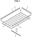
- FIG. 1 is a perspective view of a conventional solar cell module in the initial process of the assembly.
- FIG. 1 is a perspective view of a solar cell module not covered by the present invention in the initial process of the assembly.
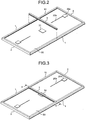
- FIG. 2 is a perspective view for showing a reinforcing frame being attached to an intermediate assembly body in which a rectangular frame is attached to the outer edge of the solar cell panel, from the back side.
- FIG. 3 is a perspective view for showing the completion of the operation of attaching the reinforcing frame to the intermediate assembly body.
- the solar cell module includes a solar panel 20 of a substantially rectangular flat plate, a shock absorbing member 31 adhered to the back surface of the solar panel 20, a rectangular frame 10 that is a rectangular frame surrounding the entire perimeter of the edge of the solar panel 20, and a reinforcing frame 3 attached to the rectangular frame 10.
- the shock absorbing member 31 is adhered at a position where it is sandwiched between the solar panel 20 and the reinforcing frame 3.
- the solar panel 20 is configured by multiple solar cells 15 that are aligned lengthwise and breadthwise to substantially form a rectangular plate.
- the rectangular frame 10 includes a pair of opposing long frames 1 and 1 and a pair of short frames 2 and 2 connected to the two ends of the long frames 1 and 1.
- the pair of long frames 1 and 1 and the pair of short frames 2 and 2 are connected to each other to form the rectangular frame 10.
- the shock absorbing member 31 is prepared with a hard material such as aluminum and hard resin, is shaped substantially into a plate, and is adhered to the back surface of the solar panel 20.
- a notch is provided in the center of the back surface of each of the long frames 1 and 1 for the reinforcing frame 3 to be engaged with.
- the reinforcing frame 3 has two end portions put into these notches from the back surface side and is engaged with the long frames 1 and 1.
- a terminal box 20a and a cable 20b extending from the terminal box 20a are provided on the back surface of the solar panel 20.
- the reinforcing frame 3 is arranged across the opposing long frames land 1 of the rectangular frame 10 and is attached to the rectangular frame 10.
- the reinforcing frame 3 is arranged at such a position that the shock absorbing member 31 is sandwiched between the reinforcing frame 3 and the solar panel 20.
- the shock absorbing member 31 is positioned between the solar panel 20 and the reinforcing frame 3 and because the shock absorbing member 31 is adhered to the back surface of the solar panel 20, it would not move or become detached.
- FIG. 4 is a perspective view of a shock absorbing member according to a first example sandwiched between the solar panel and the reinforcing frame in the solar cell module.
- FIG. 5 is a diagram of the shock absorbing member according to the first example viewed from three different directions.
- the first main surface facing the solar panel 20 is a flat surface 31a that is substantially flat so that it can be flatly attached to the solar panel 20.
- the second main surface facing the reinforcing frame 3 is an arc-in-section curved surface 31b.
- the arc-in-section curved surface 31b is a curved surface that is curved in the longitudinal direction of the reinforcing frame 3, is convexed toward the reinforcing frame 3, and is shaped into an arc in cross section.
- the arc-in-section curved surface 31b is a bent surface that is formed of a portion of a cylinder having a center axis orthogonal to the reinforcing frame 3.
- the arc-in-section curved surface 31b is curved up to positions connecting to the flat surface 31a.
- the shock absorbing member 31 does not have any end surfaces in the longitudinal direction of the reinforcing frame 3.
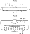
- FIG. 6 is an explanatory diagram that corresponds to a cross section of the structure incorporating a conventional shock absorbing member of FIG. 3 along line A-A, where the acting point of the snow load and the acting point of the reaction force of the reinforcing frame coincide with each other.
- a shock absorbing member 41 of a simple rectangular solid is arranged between the solar panel 20 and the reinforcing frame 3.
- the entire solar panel 20 would bow.
- the shock absorbing member 41 is a simple rectangular solid, the local stress is concentrated around the end surfaces and the like of the shock absorbing member 41. More specifically, the local stress is concentrated on a side contacted the solar panel 20 in the longitudinal end surface 41a of the shock absorbing member 41 (tobe still more specific, the center of this side).
- the solar panel 20, especially the layer made of glass tends to break at local stress concentrated points P.
- FIG. 7 is a schematic diagram of the shock absorbing member 31 according to the present embodiment scattering the reaction force of the reinforcing frame 3 side.
- the first main surface on the side of the solar panel 20 is the flat surface 31a
- the second main surface on the side of the reinforcing frame 3 is the arc-in-section curved surface 31b so that the reaction force from the reinforcing frame 3 against the snow load F is scattered along the arc-in-section curved surface 31b and thus would not concentrate on a single point.
- the solar cell module according to this example mitigates the concentration of the local stress created between the solar panel 20 and the shock absorbing member 31. Then, the solar panel 20, especially the layer made of glass, can be prevented from breaking, which improves the load bearing property of the module that tends to be degraded.
- the first main surface of the shock absorbing member 31 may be approximately a flat surface 31a and be brought into contact flatly with a large area of the solar panel 20.
- the second main surface of the shock absorbing member 31 is an arc-in-section curved surface 31b as discussed above, but it is not limited to a circular arc. Similar effects can be achieved with a curved surface that forms a smooth arc shape.
- the arc-in-section curved surface 31b may be a curved surface that forms approximately an arc shape in cross section, and similar effects can be achieved with the curved surface, for example, that partly contains flat surfaces smoothly continuing in the middle of the curved surface.
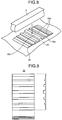
- FIG. 8 is a perspective view of a shock absorbing member arranged and sandwiched between the solar panel and the reinforcing frame in a solar cell module not covered by the present invention.
- FIG. 9 is a diagram of the shock absorbing member according to FIG. 8 viewed from three different directions.
- the first main surface that faces the solar panel 20 is a flat surface 32a that is substantially flat so that it can be brought into contact flatly with the solar panel 20.
- multiple projections 32b are formed on the second main surface facing the reinforcing frame 3 in such a manner to extend in a direction orthogonal to the reinforcing frame 3, and the curved surface smoothly connecting the ridge line (top surface) of these projections 32b forms the curved surface 32b showing an arc in cross section and convexed on the side of the solar panel 20.
- the intervals of the projections 32b are suitably designed so that the solar panel 20 would not sag into the gaps and become deformed.
- the projection 32b arranged at the very end is designed to be substantially triangular in cross section and its top surface continues to the flat surface 31a.
- the shock absorbing member 32 does not have any end surface in the longitudinal direction of the reinforcing frame 3.
- the rest of the structure is the same as that of the first example.
- FIG. 10 is a schematic diagram of the shock absorbing member 32 according to FIG. 8 scattering the reaction force of the reinforcing frame 3.
- the solar panel 20 is in contact with the ridge line (top surface) of the projections 32b of the shock absorbing member 32 and bows in the longitudinal direction of the reinforcing frame 3, forms a curved surface having an arc n cross section and convexed toward the reinforcing frame 3.
- the reaction force R from the reinforcing frame 3 side is scattered along this curved surface having an arc in cross section.
- theamountofmaterial required for the shock absorbing member 32 according to the present example is reduced for the gaps that are created, and thus the cost can be reduced.
- the curved surface formed by the solar panel 20 is not limited to the curved surface having an arc in cross section, but may be a curved surface that shows a smooth arc, and then substantially the same effects can be achieved.
- FIG. 11 is a perspective view of the shock absorbing member according to the third example in a solar cell module not covered by the present invention.
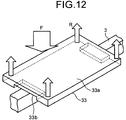
- FIG. 12 is a schematic view of the shock absorbing member according to FIG. 11 scattering the reaction force from the reinforcing frame side.
- a shock absorbing member 33 according to the present example is a plate of a substantially rectangular solid, whose first main surface facing the solar panel 20 is a flat surface 33a. Further, a notch 33b is created in the second main surface facing the reinforcing frame 3, in the center portion of each end thereof in the longitudinal direction of the reinforcing frame 3. In other words, the notches 33b are arranged in the center of the sides of the end surfaces in the longitudinal direction of the reinforcing frame 3 on the reinforcing frame 3 side.
- the notches 33b are provided in the center portions of the sides facing the sides of the solar panel 20 side on which local stress concentrated points P ( FIG. 6 ) appear in the end surfaces in the longitudinal direction of the reinforcing frame 3 in aconventional structure.
- the notches 33b are arranged in the center of the sides facing the sides on which a local stress concentrated points P appear in the conventional structure. In other words, no shock absorbing member is provided in these portions.
- the end portions where there used to be a local stress concentrated points P can escape slightly toward the notches 33b side. For this reason, the reaction force from the reinforcing frame 3 side that concentrates on the local stress concentrated points can scatter in the short-side direction of the end portion direction, as illustrated in FIG. 12 . Hence, the solar panel 20 can be prevented from breaking.
- the notches 33b produce effects as long as they are positioned at least in the center of the sides of the end surfaces of the reinforcing frame 3 side in the longitudinal direction of the reinforcing frame 3, and the notches 33b arranged across the entire length of the sides of the end surfaces of the solar panel 20 side may produce approximately the same effects.
- too large notches 33b reduces the contact area of the shock absorbing member 33 and the solar panel 20, which would produce only effects that can be obtained with a small shock absorbing member.
- FIG. 13 is a perspective view of the shock absorbing member according to an embodiment in the solar cell module of the present invention.
- FIG. 14 is a diagram of the shock absorbing member according to the present embodiment viewed from three different directions.
- a shock absorbing member 34 according to the present embodiment is in the form of bellows as a whole.
- corrugations 34a are formed on the entire two main surfaces, the first main surface facing the solar panel 20 and the second main surface facing the surface reinforcing frame 3, to extend in the transverse direction of the reinforcing frame 3 in such a manner as to expand and contract in the longitudinal direction of the reinforcing frame 3 and have resilience in the thickness direction.
- the shock absorbing member 34 When pressure is applied from the side of the solar panel 20 side or the reinforcing frame 3 side, the shock absorbing member 34 having the above structure expands in the longitudinal direction of the reinforcing frame 3 in accordance with the level of the pressure. At the same time, it shrinks in the thickness direction. In this manner, the solar panel 20 gently bows and mitigates the stress concentration between itself and the reinforcing frame 3 so that the breakage of the solar panel 20 can be reduced.
- the shock absorbing member 34 is singly provided between the solar panel 20 and the reinforcing frame 3, but the shock absorbing member 34 may be multiply provided in the longitudinal direction of the reinforcing frame 3. For example, multiple shock absorbing member 34 may be arranged at predetermined intervals in the length direction of the reinforcing frame 3. In this manner, the warping of the solar panel 20 can be reduced, and the solar panel 20 can be prevented from touching the reinforcing frame 3, and therefore the breakage of the solar panel 20 can be more reliably avoided.
- the solar cell module of the present invention is effective for a solar cell module installed in an architectural structure such as a house and a building, and is suitable especially for a solar cell module that is to be installed in a region with heavy snowfall or severe weather.
Landscapes
- Engineering & Computer Science (AREA)
- General Engineering & Computer Science (AREA)
- Mechanical Engineering (AREA)
- Physics & Mathematics (AREA)
- Combustion & Propulsion (AREA)
- Chemical & Material Sciences (AREA)
- Acoustics & Sound (AREA)
- Aviation & Aerospace Engineering (AREA)
- Sustainable Development (AREA)
- Sustainable Energy (AREA)
- Thermal Sciences (AREA)
- Life Sciences & Earth Sciences (AREA)
- Photovoltaic Devices (AREA)
Claims (3)
- Solarzellenmodul, welches aufweist:ein Solarpaneel (20), das ein transparentes Substrat enthält und durch Ausrichten von Solarzellen (15) konfiguriert ist;einen Verstärkungsrahmen (3), der auf einer Rückfläche des Solarpaneels (20) angeordnet ist; undeine Stoßabsorptionseinheit (34), die zwischen dem Solarpaneel (20) und dem Verstärkungsrahmen (3) angeordnet ist,dadurch gekennzeichnet, dass die Stoßabsorptionseinheit (34) derart gebildet ist, dass eine Wellung (34a) in den gesamten beiden Hauptflächen, die dem Solarpaneel (20) beziehungsweise dem Verstärkungsrahmen (3) zugewandt sind, gebildet ist, um sich in der Querrichtung des Verstärkungsrahmens (3) in einer solchen Weise zu erstrecken, dass sie sich in einer Längsrichtung des Verstärkungsrahmens (3) verlängert und zusammenzieht und eine Elastizität in einer Dickenrichtung hat, und die Stoßabsorptionseinheit (34) konfiguriert ist zum Verhindern, dass der Verstärkungsrahmen (3) das Solarpaneel (20) berührt, wobeidas Stoßabsorptionsteil (34) insgesamt die Form eines Faltenbalgs hat.
- Solarzellenmodul nach Anspruch 1, bei der die Stoßabsorptionseinheit (34) an der Rückfläche des Solarzellenmoduls haftet.
- Solarzellenmodul nach Anspruch 1 oder 2, bei der mehrere Stoßabsorptionseinheiten (34) in der Längsrichtung des Verstärkungsrahmens (3) angeordnet sind.
Priority Applications (1)
| Application Number | Priority Date | Filing Date | Title |
|---|---|---|---|
| EP12001836.1A EP2469607B1 (de) | 2009-04-21 | 2009-04-21 | Solarzellenmodul |
Applications Claiming Priority (3)
| Application Number | Priority Date | Filing Date | Title |
|---|---|---|---|
| EP09843638.9A EP2423971A4 (de) | 2009-04-21 | 2009-04-21 | Solarbatteriemodul |
| EP12001836.1A EP2469607B1 (de) | 2009-04-21 | 2009-04-21 | Solarzellenmodul |
| PCT/JP2009/057918 WO2010122638A1 (ja) | 2009-04-21 | 2009-04-21 | 太陽電池モジュール |
Related Parent Applications (2)
| Application Number | Title | Priority Date | Filing Date |
|---|---|---|---|
| EP09843638.9A Division EP2423971A4 (de) | 2009-04-21 | 2009-04-21 | Solarbatteriemodul |
| EP09843638.9 Division | 2009-04-21 |
Publications (3)
| Publication Number | Publication Date |
|---|---|
| EP2469607A2 EP2469607A2 (de) | 2012-06-27 |
| EP2469607A3 EP2469607A3 (de) | 2012-10-24 |
| EP2469607B1 true EP2469607B1 (de) | 2016-04-20 |
Family
ID=43010776
Family Applications (2)
| Application Number | Title | Priority Date | Filing Date |
|---|---|---|---|
| EP12001836.1A Not-in-force EP2469607B1 (de) | 2009-04-21 | 2009-04-21 | Solarzellenmodul |
| EP09843638.9A Withdrawn EP2423971A4 (de) | 2009-04-21 | 2009-04-21 | Solarbatteriemodul |
Family Applications After (1)
| Application Number | Title | Priority Date | Filing Date |
|---|---|---|---|
| EP09843638.9A Withdrawn EP2423971A4 (de) | 2009-04-21 | 2009-04-21 | Solarbatteriemodul |
Country Status (5)
| Country | Link |
|---|---|
| US (2) | US9040810B2 (de) |
| EP (2) | EP2469607B1 (de) |
| JP (1) | JP5289560B2 (de) |
| CN (1) | CN102414834B (de) |
| WO (1) | WO2010122638A1 (de) |
Families Citing this family (9)
| Publication number | Priority date | Publication date | Assignee | Title |
|---|---|---|---|---|
| US20120111393A1 (en) * | 2010-07-29 | 2012-05-10 | Joshua Conley | Integrated cartridge for adhesive-mounted photovoltaic modules |
| JP2013046025A (ja) * | 2011-08-26 | 2013-03-04 | Kaneka Corp | 太陽電池モジュール |
| CN102856410B (zh) * | 2012-09-21 | 2015-03-11 | 张正泉 | 弧形太阳能板及加工工艺 |
| EP2790232B1 (de) * | 2013-04-12 | 2019-06-19 | SOLARWATT GmbH | Glas-Glas-Solarmodul-Laminat mit Solarzellen |
| DE102014102729A1 (de) * | 2014-02-28 | 2015-09-03 | Josef Joachim Gmeiner | Photovoltaik-Modul |
| DE102014107796A1 (de) * | 2014-06-03 | 2015-12-03 | Hanwha Q Cells Gmbh | Solarmodul und Solarmodulherstellungsverfahren |
| CN104270076A (zh) * | 2014-10-21 | 2015-01-07 | 常州亿晶光电科技有限公司 | 加强型太阳能组件铝边框 |
| CN107666281A (zh) * | 2016-07-27 | 2018-02-06 | 江苏绿扬光伏科技有限公司 | 一种新型太阳能电池及其组件 |
| AU2021409960B2 (en) | 2020-12-23 | 2025-05-15 | Array Technologies, Inc. | Photovoltaic module deflection limiter |
Family Cites Families (30)
| Publication number | Priority date | Publication date | Assignee | Title |
|---|---|---|---|---|
| BE392530A (de) * | 1932-10-26 | |||
| US2727407A (en) | 1950-09-12 | 1955-12-20 | Syntron Co | Flexible elastomer |
| US4286006A (en) * | 1977-01-26 | 1981-08-25 | Boelter Industries, Inc. | Corrugated material |
| US4167644A (en) * | 1978-09-29 | 1979-09-11 | Exxon Research & Engineering Co. | Solar cell module |
| JPS635595Y2 (de) * | 1980-06-10 | 1988-02-16 | ||
| US4505974A (en) | 1983-10-03 | 1985-03-19 | Formica Corporation | Decorative laminate having mar-resistant surface |
| US4974820A (en) * | 1986-05-09 | 1990-12-04 | Suzuki Sogyo Kabushiki Kaisha | Bellows type shock absorber |
| US4832001A (en) * | 1987-05-28 | 1989-05-23 | Zomeworks Corporation | Lightweight solar panel support |
| JPH0726851Y2 (ja) | 1990-10-09 | 1995-06-14 | シャープ株式会社 | 太陽電池 |
| US5435087A (en) * | 1993-12-15 | 1995-07-25 | Karkar; Maurice N. | Solar powered display device |
| JP3629718B2 (ja) | 1994-03-30 | 2005-03-16 | 東洋紡績株式会社 | 樹脂製衝撃吸収ブロック |
| JP3089172B2 (ja) | 1994-12-21 | 2000-09-18 | シャープ株式会社 | 屋根設置型装置 |
| SE504353C2 (sv) | 1995-06-19 | 1997-01-20 | Perstorp Ab | Förfarande för framställning av ett dekorativt härdplastlaminat |
| JP3457783B2 (ja) * | 1995-11-28 | 2003-10-20 | シャープ株式会社 | 太陽電池モジュールおよびその架台取付構造 |
| US5647915A (en) * | 1996-06-13 | 1997-07-15 | Zukerman; Charles | Solar energy panel |
| JP3674234B2 (ja) | 1997-04-18 | 2005-07-20 | 株式会社カネカ | 大型太陽電池モジュール |
| US6500372B1 (en) | 1997-04-25 | 2002-12-31 | Premador, Inc. | Method for the moulding of wood fiber board |
| GB2340060B (en) | 1998-07-29 | 2003-08-13 | Mdf Inc | Method of manufacturing a molded door skin from a flat wood composite, door skin produced therefrom and door manufactured therewith |
| JP2002223911A (ja) * | 2001-02-05 | 2002-08-13 | Aqua New Tech:Kk | 密閉式額縁 |
| JP2003105940A (ja) * | 2001-09-28 | 2003-04-09 | Sekisui Chem Co Ltd | 太陽電池モジュールの設置構造 |
| JP2004006625A (ja) | 2002-03-27 | 2004-01-08 | Kyocera Corp | 太陽電池モジュールおよび太陽電池アレイ |
| JP2004146765A (ja) * | 2002-08-30 | 2004-05-20 | Kyocera Corp | 太陽電池アレイ |
| US20050161074A1 (en) * | 2003-12-16 | 2005-07-28 | Paul Garvison | Photovoltaic module mounting unit and system |
| JP4690666B2 (ja) * | 2004-06-25 | 2011-06-01 | 本田技研工業株式会社 | 車両用燃料タンクの防振支持構造 |
| US7300032B2 (en) | 2005-01-25 | 2007-11-27 | Atire Terchnologies, Inc. | Vibration and noise abatement pad |
| US7956279B2 (en) * | 2005-03-18 | 2011-06-07 | Kyocera Corporation | Solar cell module and solar cell array |
| US7562494B2 (en) * | 2005-04-28 | 2009-07-21 | Platts Robert E | Retrofitting apparatus and method for securing roof frames against winds |
| JP2007335622A (ja) * | 2006-06-15 | 2007-12-27 | Fujitsu Ltd | 電子装置 |
| US8347564B2 (en) | 2007-04-24 | 2013-01-08 | Mitsubishi Electric Corporation | Solar cell module |
| EP2157619A4 (de) * | 2007-05-14 | 2012-03-07 | Mitsubishi Electric Corp | Solarbatteriemodulanordnung |
-
2009
- 2009-04-21 US US13/263,209 patent/US9040810B2/en not_active Expired - Fee Related
- 2009-04-21 WO PCT/JP2009/057918 patent/WO2010122638A1/ja not_active Ceased
- 2009-04-21 EP EP12001836.1A patent/EP2469607B1/de not_active Not-in-force
- 2009-04-21 JP JP2011510115A patent/JP5289560B2/ja not_active Expired - Fee Related
- 2009-04-21 CN CN200980158892.5A patent/CN102414834B/zh not_active Expired - Fee Related
- 2009-04-21 EP EP09843638.9A patent/EP2423971A4/de not_active Withdrawn
-
2012
- 2012-03-13 US US13/418,826 patent/US20120192929A1/en not_active Abandoned
Also Published As
| Publication number | Publication date |
|---|---|
| US20120024354A1 (en) | 2012-02-02 |
| EP2423971A1 (de) | 2012-02-29 |
| JP5289560B2 (ja) | 2013-09-11 |
| US9040810B2 (en) | 2015-05-26 |
| CN102414834B (zh) | 2014-08-27 |
| CN102414834A (zh) | 2012-04-11 |
| EP2423971A4 (de) | 2013-05-15 |
| JPWO2010122638A1 (ja) | 2012-10-22 |
| WO2010122638A1 (ja) | 2010-10-28 |
| EP2469607A2 (de) | 2012-06-27 |
| US20120192929A1 (en) | 2012-08-02 |
| EP2469607A3 (de) | 2012-10-24 |
Similar Documents
| Publication | Publication Date | Title |
|---|---|---|
| US9040810B2 (en) | Solar cell module | |
| EP2157619A1 (de) | Solarbatteriemodulanordnung | |
| CN101663763B (zh) | 太阳能电池模块 | |
| EP2772946A1 (de) | Solarzellenmodul und solarzellenarray | |
| WO2012011320A1 (ja) | 太陽電池アレイ | |
| US20150068589A1 (en) | Reinforcing frame and solar battery module | |
| WO2008122046A3 (en) | Method and system for assembling a solar cell package | |
| JP4451481B2 (ja) | 太陽電池モジュール用架台、及び取付構造 | |
| US8859881B2 (en) | Solar battery module | |
| JP5230585B2 (ja) | 太陽電池モジュール及びその製造方法 | |
| JP6789315B2 (ja) | 太陽電池装置 | |
| CN102208469A (zh) | 太阳能电池模块 | |
| AU2016341146A1 (en) | Rear face element for a solar module | |
| JP2011129682A (ja) | 太陽電池モジュール | |
| JP5519998B2 (ja) | 太陽光発電シートの取付け構造 | |
| JP5174939B2 (ja) | 太陽電池モジュール | |
| CN102623525B (zh) | 太阳能电池组件 | |
| JP5574930B2 (ja) | 太陽電池アレイ | |
| KR102652915B1 (ko) | 태양광모듈의 프레임 | |
| US12424968B2 (en) | Solar power generation panel structure and reinforcing plate for solar power generation panel structure | |
| CN220798179U (zh) | 一种太阳能电池组件安全防护框架 | |
| CN120979318A (zh) | 一种光伏组件、光伏电站及应用于光伏组件的边框结构 | |
| JP6920950B2 (ja) | 太陽電池装置 | |
| TWI413750B (zh) | 太陽能電池面板及其安裝結構 | |
| JP2024122747A (ja) | 太陽電池モジュール |
Legal Events
| Date | Code | Title | Description |
|---|---|---|---|
| 17P | Request for examination filed |
Effective date: 20120319 |
|
| AC | Divisional application: reference to earlier application |
Ref document number: 2423971 Country of ref document: EP Kind code of ref document: P |
|
| AK | Designated contracting states |
Kind code of ref document: A2 Designated state(s): AT BE BG CH CY CZ DE DK EE ES FI FR GB GR HR HU IE IS IT LI LT LU LV MC MK MT NL NO PL PT RO SE SI SK TR |
|
| PUAI | Public reference made under article 153(3) epc to a published international application that has entered the european phase |
Free format text: ORIGINAL CODE: 0009012 |
|
| TPAC | Observations by third parties |
Free format text: ORIGINAL CODE: EPIDOSNTIPA |
|
| PUAL | Search report despatched |
Free format text: ORIGINAL CODE: 0009013 |
|
| AK | Designated contracting states |
Kind code of ref document: A3 Designated state(s): AT BE BG CH CY CZ DE DK EE ES FI FR GB GR HR HU IE IS IT LI LT LU LV MC MK MT NL NO PL PT RO SE SI SK TR |
|
| RIC1 | Information provided on ipc code assigned before grant |
Ipc: H01L 31/042 20060101AFI20120918BHEP |
|
| 17Q | First examination report despatched |
Effective date: 20140825 |
|
| GRAP | Despatch of communication of intention to grant a patent |
Free format text: ORIGINAL CODE: EPIDOSNIGR1 |
|
| INTG | Intention to grant announced |
Effective date: 20151210 |
|
| GRAS | Grant fee paid |
Free format text: ORIGINAL CODE: EPIDOSNIGR3 |
|
| GRAA | (expected) grant |
Free format text: ORIGINAL CODE: 0009210 |
|
| AC | Divisional application: reference to earlier application |
Ref document number: 2423971 Country of ref document: EP Kind code of ref document: P |
|
| AK | Designated contracting states |
Kind code of ref document: B1 Designated state(s): AT BE BG CH CY CZ DE DK EE ES FI FR GB GR HR HU IE IS IT LI LT LU LV MC MK MT NL NO PL PT RO SE SI SK TR |
|
| REG | Reference to a national code |
Ref country code: GB Ref legal event code: FG4D |
|
| REG | Reference to a national code |
Ref country code: CH Ref legal event code: EP |
|
| REG | Reference to a national code |
Ref country code: AT Ref legal event code: REF Ref document number: 793271 Country of ref document: AT Kind code of ref document: T Effective date: 20160515 |
|
| REG | Reference to a national code |
Ref country code: IE Ref legal event code: FG4D |
|
| REG | Reference to a national code |
Ref country code: DE Ref legal event code: R096 Ref document number: 602009038143 Country of ref document: DE |
|
| REG | Reference to a national code |
Ref country code: LT Ref legal event code: MG4D |
|
| PG25 | Lapsed in a contracting state [announced via postgrant information from national office to epo] |
Ref country code: BE Free format text: LAPSE BECAUSE OF NON-PAYMENT OF DUE FEES Effective date: 20160430 |
|
| REG | Reference to a national code |
Ref country code: AT Ref legal event code: MK05 Ref document number: 793271 Country of ref document: AT Kind code of ref document: T Effective date: 20160420 |
|
| REG | Reference to a national code |
Ref country code: NL Ref legal event code: MP Effective date: 20160420 |
|
| PG25 | Lapsed in a contracting state [announced via postgrant information from national office to epo] |
Ref country code: FI Free format text: LAPSE BECAUSE OF FAILURE TO SUBMIT A TRANSLATION OF THE DESCRIPTION OR TO PAY THE FEE WITHIN THE PRESCRIBED TIME-LIMIT Effective date: 20160420 Ref country code: PL Free format text: LAPSE BECAUSE OF FAILURE TO SUBMIT A TRANSLATION OF THE DESCRIPTION OR TO PAY THE FEE WITHIN THE PRESCRIBED TIME-LIMIT Effective date: 20160420 Ref country code: NO Free format text: LAPSE BECAUSE OF FAILURE TO SUBMIT A TRANSLATION OF THE DESCRIPTION OR TO PAY THE FEE WITHIN THE PRESCRIBED TIME-LIMIT Effective date: 20160720 Ref country code: LT Free format text: LAPSE BECAUSE OF FAILURE TO SUBMIT A TRANSLATION OF THE DESCRIPTION OR TO PAY THE FEE WITHIN THE PRESCRIBED TIME-LIMIT Effective date: 20160420 Ref country code: NL Free format text: LAPSE BECAUSE OF FAILURE TO SUBMIT A TRANSLATION OF THE DESCRIPTION OR TO PAY THE FEE WITHIN THE PRESCRIBED TIME-LIMIT Effective date: 20160420 |
|
| PG25 | Lapsed in a contracting state [announced via postgrant information from national office to epo] |
Ref country code: LV Free format text: LAPSE BECAUSE OF FAILURE TO SUBMIT A TRANSLATION OF THE DESCRIPTION OR TO PAY THE FEE WITHIN THE PRESCRIBED TIME-LIMIT Effective date: 20160420 Ref country code: PT Free format text: LAPSE BECAUSE OF FAILURE TO SUBMIT A TRANSLATION OF THE DESCRIPTION OR TO PAY THE FEE WITHIN THE PRESCRIBED TIME-LIMIT Effective date: 20160822 Ref country code: GR Free format text: LAPSE BECAUSE OF FAILURE TO SUBMIT A TRANSLATION OF THE DESCRIPTION OR TO PAY THE FEE WITHIN THE PRESCRIBED TIME-LIMIT Effective date: 20160721 Ref country code: AT Free format text: LAPSE BECAUSE OF FAILURE TO SUBMIT A TRANSLATION OF THE DESCRIPTION OR TO PAY THE FEE WITHIN THE PRESCRIBED TIME-LIMIT Effective date: 20160420 Ref country code: HR Free format text: LAPSE BECAUSE OF FAILURE TO SUBMIT A TRANSLATION OF THE DESCRIPTION OR TO PAY THE FEE WITHIN THE PRESCRIBED TIME-LIMIT Effective date: 20160420 Ref country code: SE Free format text: LAPSE BECAUSE OF FAILURE TO SUBMIT A TRANSLATION OF THE DESCRIPTION OR TO PAY THE FEE WITHIN THE PRESCRIBED TIME-LIMIT Effective date: 20160420 Ref country code: ES Free format text: LAPSE BECAUSE OF FAILURE TO SUBMIT A TRANSLATION OF THE DESCRIPTION OR TO PAY THE FEE WITHIN THE PRESCRIBED TIME-LIMIT Effective date: 20160420 |
|
| REG | Reference to a national code |
Ref country code: CH Ref legal event code: PL |
|
| PG25 | Lapsed in a contracting state [announced via postgrant information from national office to epo] |
Ref country code: BE Free format text: LAPSE BECAUSE OF FAILURE TO SUBMIT A TRANSLATION OF THE DESCRIPTION OR TO PAY THE FEE WITHIN THE PRESCRIBED TIME-LIMIT Effective date: 20160420 Ref country code: IT Free format text: LAPSE BECAUSE OF FAILURE TO SUBMIT A TRANSLATION OF THE DESCRIPTION OR TO PAY THE FEE WITHIN THE PRESCRIBED TIME-LIMIT Effective date: 20160420 |
|
| REG | Reference to a national code |
Ref country code: DE Ref legal event code: R097 Ref document number: 602009038143 Country of ref document: DE |
|
| REG | Reference to a national code |
Ref country code: IE Ref legal event code: MM4A |
|
| PG25 | Lapsed in a contracting state [announced via postgrant information from national office to epo] |
Ref country code: DK Free format text: LAPSE BECAUSE OF FAILURE TO SUBMIT A TRANSLATION OF THE DESCRIPTION OR TO PAY THE FEE WITHIN THE PRESCRIBED TIME-LIMIT Effective date: 20160420 Ref country code: MC Free format text: LAPSE BECAUSE OF FAILURE TO SUBMIT A TRANSLATION OF THE DESCRIPTION OR TO PAY THE FEE WITHIN THE PRESCRIBED TIME-LIMIT Effective date: 20160420 Ref country code: EE Free format text: LAPSE BECAUSE OF FAILURE TO SUBMIT A TRANSLATION OF THE DESCRIPTION OR TO PAY THE FEE WITHIN THE PRESCRIBED TIME-LIMIT Effective date: 20160420 Ref country code: SK Free format text: LAPSE BECAUSE OF FAILURE TO SUBMIT A TRANSLATION OF THE DESCRIPTION OR TO PAY THE FEE WITHIN THE PRESCRIBED TIME-LIMIT Effective date: 20160420 Ref country code: RO Free format text: LAPSE BECAUSE OF FAILURE TO SUBMIT A TRANSLATION OF THE DESCRIPTION OR TO PAY THE FEE WITHIN THE PRESCRIBED TIME-LIMIT Effective date: 20160420 Ref country code: CZ Free format text: LAPSE BECAUSE OF FAILURE TO SUBMIT A TRANSLATION OF THE DESCRIPTION OR TO PAY THE FEE WITHIN THE PRESCRIBED TIME-LIMIT Effective date: 20160420 Ref country code: CH Free format text: LAPSE BECAUSE OF NON-PAYMENT OF DUE FEES Effective date: 20160430 Ref country code: LI Free format text: LAPSE BECAUSE OF NON-PAYMENT OF DUE FEES Effective date: 20160430 |
|
| PLBE | No opposition filed within time limit |
Free format text: ORIGINAL CODE: 0009261 |
|
| STAA | Information on the status of an ep patent application or granted ep patent |
Free format text: STATUS: NO OPPOSITION FILED WITHIN TIME LIMIT |
|
| REG | Reference to a national code |
Ref country code: FR Ref legal event code: ST Effective date: 20170201 |
|
| GBPC | Gb: european patent ceased through non-payment of renewal fee |
Effective date: 20160720 |
|
| 26N | No opposition filed |
Effective date: 20170123 |
|
| PG25 | Lapsed in a contracting state [announced via postgrant information from national office to epo] |
Ref country code: FR Free format text: LAPSE BECAUSE OF NON-PAYMENT OF DUE FEES Effective date: 20160620 |
|
| PG25 | Lapsed in a contracting state [announced via postgrant information from national office to epo] |
Ref country code: IE Free format text: LAPSE BECAUSE OF NON-PAYMENT OF DUE FEES Effective date: 20160421 Ref country code: GB Free format text: LAPSE BECAUSE OF NON-PAYMENT OF DUE FEES Effective date: 20160720 Ref country code: SI Free format text: LAPSE BECAUSE OF FAILURE TO SUBMIT A TRANSLATION OF THE DESCRIPTION OR TO PAY THE FEE WITHIN THE PRESCRIBED TIME-LIMIT Effective date: 20160420 |
|
| REG | Reference to a national code |
Ref country code: DE Ref legal event code: R084 Ref document number: 602009038143 Country of ref document: DE |
|
| PG25 | Lapsed in a contracting state [announced via postgrant information from national office to epo] |
Ref country code: HU Free format text: LAPSE BECAUSE OF FAILURE TO SUBMIT A TRANSLATION OF THE DESCRIPTION OR TO PAY THE FEE WITHIN THE PRESCRIBED TIME-LIMIT; INVALID AB INITIO Effective date: 20090421 Ref country code: CY Free format text: LAPSE BECAUSE OF FAILURE TO SUBMIT A TRANSLATION OF THE DESCRIPTION OR TO PAY THE FEE WITHIN THE PRESCRIBED TIME-LIMIT Effective date: 20160420 |
|
| PG25 | Lapsed in a contracting state [announced via postgrant information from national office to epo] |
Ref country code: MT Free format text: LAPSE BECAUSE OF NON-PAYMENT OF DUE FEES Effective date: 20160430 Ref country code: LU Free format text: LAPSE BECAUSE OF NON-PAYMENT OF DUE FEES Effective date: 20160421 Ref country code: TR Free format text: LAPSE BECAUSE OF FAILURE TO SUBMIT A TRANSLATION OF THE DESCRIPTION OR TO PAY THE FEE WITHIN THE PRESCRIBED TIME-LIMIT Effective date: 20160420 Ref country code: MK Free format text: LAPSE BECAUSE OF FAILURE TO SUBMIT A TRANSLATION OF THE DESCRIPTION OR TO PAY THE FEE WITHIN THE PRESCRIBED TIME-LIMIT Effective date: 20160420 Ref country code: IS Free format text: LAPSE BECAUSE OF FAILURE TO SUBMIT A TRANSLATION OF THE DESCRIPTION OR TO PAY THE FEE WITHIN THE PRESCRIBED TIME-LIMIT Effective date: 20160420 |
|
| PG25 | Lapsed in a contracting state [announced via postgrant information from national office to epo] |
Ref country code: BG Free format text: LAPSE BECAUSE OF FAILURE TO SUBMIT A TRANSLATION OF THE DESCRIPTION OR TO PAY THE FEE WITHIN THE PRESCRIBED TIME-LIMIT Effective date: 20160420 |
|
| PGFP | Annual fee paid to national office [announced via postgrant information from national office to epo] |
Ref country code: DE Payment date: 20200408 Year of fee payment: 12 |
|
| REG | Reference to a national code |
Ref country code: DE Ref legal event code: R119 Ref document number: 602009038143 Country of ref document: DE |
|
| PG25 | Lapsed in a contracting state [announced via postgrant information from national office to epo] |
Ref country code: DE Free format text: LAPSE BECAUSE OF NON-PAYMENT OF DUE FEES Effective date: 20211103 |