EP2469048A2 - Nockenwellenversteller - Google Patents
Nockenwellenversteller Download PDFInfo
- Publication number
- EP2469048A2 EP2469048A2 EP11181846A EP11181846A EP2469048A2 EP 2469048 A2 EP2469048 A2 EP 2469048A2 EP 11181846 A EP11181846 A EP 11181846A EP 11181846 A EP11181846 A EP 11181846A EP 2469048 A2 EP2469048 A2 EP 2469048A2
- Authority
- EP
- European Patent Office
- Prior art keywords
- stator
- adapter sleeve
- oil
- rotor
- drive wheel
- Prior art date
- Legal status (The legal status is an assumption and is not a legal conclusion. Google has not performed a legal analysis and makes no representation as to the accuracy of the status listed.)
- Granted
Links
- 238000007789 sealing Methods 0.000 description 11
- 239000002131 composite material Substances 0.000 description 7
- 230000015572 biosynthetic process Effects 0.000 description 5
- 238000005755 formation reaction Methods 0.000 description 5
- 239000002184 metal Substances 0.000 description 5
- 229910052751 metal Inorganic materials 0.000 description 5
- 238000004519 manufacturing process Methods 0.000 description 4
- 239000003129 oil well Substances 0.000 description 3
- 239000004033 plastic Substances 0.000 description 3
- 229920003023 plastic Polymers 0.000 description 3
- 238000002485 combustion reaction Methods 0.000 description 2
- 230000000295 complement effect Effects 0.000 description 2
- 238000005553 drilling Methods 0.000 description 2
- 239000000463 material Substances 0.000 description 2
- 241000196324 Embryophyta Species 0.000 description 1
- 241000209035 Ilex Species 0.000 description 1
- 230000005540 biological transmission Effects 0.000 description 1
- 238000000576 coating method Methods 0.000 description 1
- 238000004891 communication Methods 0.000 description 1
- 150000001875 compounds Chemical class 0.000 description 1
- 238000010276 construction Methods 0.000 description 1
- 230000000694 effects Effects 0.000 description 1
- RDYMFSUJUZBWLH-UHFFFAOYSA-N endosulfan Chemical compound C12COS(=O)OCC2C2(Cl)C(Cl)=C(Cl)C1(Cl)C2(Cl)Cl RDYMFSUJUZBWLH-UHFFFAOYSA-N 0.000 description 1
- 238000001125 extrusion Methods 0.000 description 1
- 239000000446 fuel Substances 0.000 description 1
- 238000009434 installation Methods 0.000 description 1
- 239000007788 liquid Substances 0.000 description 1
- 230000001050 lubricating effect Effects 0.000 description 1
- 239000006262 metallic foam Substances 0.000 description 1
- 150000002739 metals Chemical class 0.000 description 1
- 238000003801 milling Methods 0.000 description 1
- 230000000149 penetrating effect Effects 0.000 description 1
- 230000035515 penetration Effects 0.000 description 1
- 238000005245 sintering Methods 0.000 description 1
- 238000009423 ventilation Methods 0.000 description 1
- 238000004804 winding Methods 0.000 description 1
Images


Classifications
-
- F—MECHANICAL ENGINEERING; LIGHTING; HEATING; WEAPONS; BLASTING
- F01—MACHINES OR ENGINES IN GENERAL; ENGINE PLANTS IN GENERAL; STEAM ENGINES
- F01L—CYCLICALLY OPERATING VALVES FOR MACHINES OR ENGINES
- F01L1/00—Valve-gear or valve arrangements, e.g. lift-valve gear
- F01L1/34—Valve-gear or valve arrangements, e.g. lift-valve gear characterised by the provision of means for changing the timing of the valves without changing the duration of opening and without affecting the magnitude of the valve lift
- F01L1/344—Valve-gear or valve arrangements, e.g. lift-valve gear characterised by the provision of means for changing the timing of the valves without changing the duration of opening and without affecting the magnitude of the valve lift changing the angular relationship between crankshaft and camshaft, e.g. using helicoidal gear
- F01L1/3442—Valve-gear or valve arrangements, e.g. lift-valve gear characterised by the provision of means for changing the timing of the valves without changing the duration of opening and without affecting the magnitude of the valve lift changing the angular relationship between crankshaft and camshaft, e.g. using helicoidal gear using hydraulic chambers with variable volume to transmit the rotating force
-
- F—MECHANICAL ENGINEERING; LIGHTING; HEATING; WEAPONS; BLASTING
- F01—MACHINES OR ENGINES IN GENERAL; ENGINE PLANTS IN GENERAL; STEAM ENGINES
- F01L—CYCLICALLY OPERATING VALVES FOR MACHINES OR ENGINES
- F01L1/00—Valve-gear or valve arrangements, e.g. lift-valve gear
- F01L1/34—Valve-gear or valve arrangements, e.g. lift-valve gear characterised by the provision of means for changing the timing of the valves without changing the duration of opening and without affecting the magnitude of the valve lift
- F01L1/344—Valve-gear or valve arrangements, e.g. lift-valve gear characterised by the provision of means for changing the timing of the valves without changing the duration of opening and without affecting the magnitude of the valve lift changing the angular relationship between crankshaft and camshaft, e.g. using helicoidal gear
- F01L1/3442—Valve-gear or valve arrangements, e.g. lift-valve gear characterised by the provision of means for changing the timing of the valves without changing the duration of opening and without affecting the magnitude of the valve lift changing the angular relationship between crankshaft and camshaft, e.g. using helicoidal gear using hydraulic chambers with variable volume to transmit the rotating force
- F01L2001/34423—Details relating to the hydraulic feeding circuit
-
- F—MECHANICAL ENGINEERING; LIGHTING; HEATING; WEAPONS; BLASTING
- F01—MACHINES OR ENGINES IN GENERAL; ENGINE PLANTS IN GENERAL; STEAM ENGINES
- F01L—CYCLICALLY OPERATING VALVES FOR MACHINES OR ENGINES
- F01L1/00—Valve-gear or valve arrangements, e.g. lift-valve gear
- F01L1/34—Valve-gear or valve arrangements, e.g. lift-valve gear characterised by the provision of means for changing the timing of the valves without changing the duration of opening and without affecting the magnitude of the valve lift
- F01L1/344—Valve-gear or valve arrangements, e.g. lift-valve gear characterised by the provision of means for changing the timing of the valves without changing the duration of opening and without affecting the magnitude of the valve lift changing the angular relationship between crankshaft and camshaft, e.g. using helicoidal gear
- F01L1/3442—Valve-gear or valve arrangements, e.g. lift-valve gear characterised by the provision of means for changing the timing of the valves without changing the duration of opening and without affecting the magnitude of the valve lift changing the angular relationship between crankshaft and camshaft, e.g. using helicoidal gear using hydraulic chambers with variable volume to transmit the rotating force
- F01L2001/3445—Details relating to the hydraulic means for changing the angular relationship
- F01L2001/34453—Locking means between driving and driven members
- F01L2001/34469—Lock movement parallel to camshaft axis
-
- F—MECHANICAL ENGINEERING; LIGHTING; HEATING; WEAPONS; BLASTING
- F01—MACHINES OR ENGINES IN GENERAL; ENGINE PLANTS IN GENERAL; STEAM ENGINES
- F01L—CYCLICALLY OPERATING VALVES FOR MACHINES OR ENGINES
- F01L1/00—Valve-gear or valve arrangements, e.g. lift-valve gear
- F01L1/34—Valve-gear or valve arrangements, e.g. lift-valve gear characterised by the provision of means for changing the timing of the valves without changing the duration of opening and without affecting the magnitude of the valve lift
- F01L1/344—Valve-gear or valve arrangements, e.g. lift-valve gear characterised by the provision of means for changing the timing of the valves without changing the duration of opening and without affecting the magnitude of the valve lift changing the angular relationship between crankshaft and camshaft, e.g. using helicoidal gear
- F01L1/3442—Valve-gear or valve arrangements, e.g. lift-valve gear characterised by the provision of means for changing the timing of the valves without changing the duration of opening and without affecting the magnitude of the valve lift changing the angular relationship between crankshaft and camshaft, e.g. using helicoidal gear using hydraulic chambers with variable volume to transmit the rotating force
- F01L2001/3445—Details relating to the hydraulic means for changing the angular relationship
- F01L2001/34483—Phaser return springs
-
- F—MECHANICAL ENGINEERING; LIGHTING; HEATING; WEAPONS; BLASTING
- F01—MACHINES OR ENGINES IN GENERAL; ENGINE PLANTS IN GENERAL; STEAM ENGINES
- F01L—CYCLICALLY OPERATING VALVES FOR MACHINES OR ENGINES
- F01L2250/00—Camshaft drives characterised by their transmission means
- F01L2250/04—Camshaft drives characterised by their transmission means the camshaft being driven by belts
-
- F—MECHANICAL ENGINEERING; LIGHTING; HEATING; WEAPONS; BLASTING
- F01—MACHINES OR ENGINES IN GENERAL; ENGINE PLANTS IN GENERAL; STEAM ENGINES
- F01L—CYCLICALLY OPERATING VALVES FOR MACHINES OR ENGINES
- F01L2301/00—Using particular materials
-
- F—MECHANICAL ENGINEERING; LIGHTING; HEATING; WEAPONS; BLASTING
- F01—MACHINES OR ENGINES IN GENERAL; ENGINE PLANTS IN GENERAL; STEAM ENGINES
- F01L—CYCLICALLY OPERATING VALVES FOR MACHINES OR ENGINES
- F01L2303/00—Manufacturing of components used in valve arrangements
- F01L2303/01—Tools for producing, mounting or adjusting, e.g. some part of the distribution
Definitions
- the invention relates to a camshaft adjuster.
- Camshaft adjusters are used in internal combustion engines for varying the timing of the combustion chamber valves. Adjusting the timing to the current load lowers fuel consumption and emissions.
- a common type is the wellgelzellenversteller.
- Vane adjusters include a stator, a rotor and a drive wheel. The rotor is usually non-rotatably connected to the camshaft. The stator and the drive wheel are also interconnected with the rotor coaxial with the stator and within the stator. Rotor and stator characterize oil chambers, which can be acted upon by oil pressure and allow a relative movement between the stator and rotor. Furthermore, the vane cell adjusters have various sealing lids. The composite of stator, drive wheel and sealing cover is formed by a plurality of screw connections.
- the object of the invention is to provide a camshaft adjuster, which is particularly simple in construction and has a reliable connection to the camshaft.
- the camshaft adjuster comprises a drive wheel, a stator and a rotor, wherein the rotor relative to the stator has a rotational degree of freedom and the rotor is fixed axially relative to the stator, wherein the camshaft adjuster arranged coaxially to the axis of rotation of the drive wheel an adapter sleeve and a connecting sleeve, wherein the adapter sleeve and the connecting sleeve are connected to one another on the one hand and on the other hand form an axial fixation of rotor, stator and drive wheel.
- the rotor, the adapter sleeve and the connecting sleeve form a rotationally fixed unit, which is connectable to a camshaft end. This can be omitted a variety of screws, rivets, pins.
- the adapter sleeve is formed connectable with a camshaft end.
- the camshaft end is designed such that the adapter sleeve is centered over a collar or paragraph. This centering minimizes coaxiality errors.
- the end-side, camshaft-facing end of the adapter sleeve forms an advantageously planar contact surface with the camshaft in order to absorb high forces.
- the centering and the contact surface can be achieved by e.g. Knurled be such a surface that the reliability of the connection is increased.
- the adapter sleeve is designed to carry oil.
- the pipe of oil through the adapter sleeve forms oil paths short and it is low oil losses achieved by a small number of sealing points coupled components.
- Other sleeves used in the camshaft adjuster may also be formed oil leading.
- the sleeves used can be provided with sealing elements.
- the adapter sleeve and the connection sleeve have one or more axial stops. These stops form a position fixing, wherein the rotor is braced and the drive wheel and the stator are provided with little axial play.
- the advantage here is the integral design of these attacks as changes in diameter on the outer circumferential surfaces of the adapter sleeve and the connecting sleeve.
- the adapter sleeve has a bearing for the drive wheel.
- the adapter sleeve with the bearing is formed directly connectable to the camshaft end. Since a camshaft bearing is usually arranged at the end of the camshaft, forces are advantageously absorbed on the cylinder head.
- the adapter sleeve is connected to the connecting sleeve by a thread.
- the advantage here is the disassembly option. Internal and external threads as well as left and right-hand threads can be used. Furthermore, a thread-forming design on one of the two sleeves is conceivable.
- connection sleeve with the adapter sleeve by an oversize connection, or press fit, braced. This ensures that when mounting the camshaft adjuster with the camshaft end, the central screw further strengthens and secures the interference fit.
- the press fit can be made more efficient by knurling the surfaces of the sleeves.
- the stator is positively connected to the drive wheel and centered on this.
- the form fit transfers the torque from the drive wheel to the stator.
- a seal can be provided, which forms an oil-tight space in the stator.
- the axial cohesion between the stator and the drive wheel is formed via axial stops and through the connection between the adapter sleeve and the connecting sleeve.
- pins, rivets or other standard parts can be used to form the torque transmission between the stator and the drive wheel.
- Advantageous in the use of standard parts are low production costs.
- the drive wheel, the stator and the rotor are particularly well centered to each other and achieved a very accurate positioning each other.
- the outer diameters are formed differently in diameter.
- the drive wheel, stator and rotor are centered on a common outer diameter, which is simple and inexpensive to produce.
- functions such as centering and axial fixation can be realized via additional sleeves.
- one of the sleeves has a centering for a stator, another sleeve a centering for a rotor, etc. Any combination of the functions and the number of sleeves is conceivable.
- the adapter sleeve, the connecting sleeve and possibly further sleeves can be interconnected with additional means.
- additional means can screws, washers, rings, pins, or similar. be.
- the sleeves have a passage opening for the penetrating arrangement of a central screw, the camshaft adjuster attached to the camshaft end.
- a sealing cover or a cover can be arranged on the unit, which seals the unit oil-tight against the environment.
- adjusting unit such as sealing covers, bearings, locking units or oil guide plates, can be fixed by the adapter sleeve and the connecting sleeve as well as by additional sleeves.
- Locking means may be circlips, circlips, nuts, screws or, advantageously, the sleeve itself. In this case, material is crimped by the sleeve, bent or otherwise reshaped.
- An embodiment of the sleeve in sheet metal is advantageous.
- the adapter sleeve on the camshaft-side end face concentric to the central axis circumferential recess.
- This recess is in communication with oil supply holes of the camshaft.
- the adapter sleeve axially parallel bores extending cut this recess. The bore exits open at the other end of the adapter sleeve in a first oil chamber.
- the adapter sleeve has a concentric passage opening. This passage opening is penetrated by a central screw. A gap remains between the central screw and the diameter of the passage opening. This gap represents another oil supply.
- the adapter sleeve has radial oil holes that connect the outer diameter with the inner diameter of the through hole.
- the radial oil holes are angularly offset from the axial oil holes, so that no overlap of the holes and thus no short circuit in the oil circuit is formed.
- the radial oil holes can also open into a circumferential groove, from which the oil is then forwarded to the corresponding oil chamber.
- the oil passages may be arranged in an oil-carrying sleeve angularly oriented to an oil supply source.
- the sleeves In order to realize an angle-oriented oil supply between the sleeves, the sleeves have anti-rotation elements. Thus, a reliable arrangement of the oil passages can be formed.
- a sleeve may have a thread for attachment to a camshaft. This advantageously can be dispensed with attachment to a central screw and the sleeves are formed without through hole for a central screw.
- the thread may be formed as an internal or external thread and advantageously justified in the direction of rotation of the drive wheel have a left or right-hand thread.
- the sleeves used to reduce the weight inside hollow, perforated, slotted or formed as a cage may be filled, e.g. made of metal foam.
- a hub is formed on the stator, which is located at one end of the stator.
- This hub can advantageously be determined by the sheet thickness of the stator.
- the hub supports the stator on a sleeve, preferably the connecting sleeve.
- a spring element is arranged between the stator and the rotor.
- the spring element braces the stator with the rotor in an advantageous direction with each other.
- the winding body of the spring is advantageously mounted or guided on an outer diameter of one of the sleeves used, for example the adapter sleeve.
- the spring may also be guided on the hub of the rotor or the stator or other components.
- the sleeves used, or at least one of them formed as a sheet metal part.
- This lowers manufacturing costs.
- other manufacturing processes such as sintering, extrusion, deep drawing or milling can be used.
- materials used such as metals, plastics or composite materials conceivable. To minimize wear coatings can be provided.
- the camshaft adjuster is fastened by a central screw at the camshaft end.
- the central bolt penetrates the sleeves used, which hold the camshaft adjuster together.
- the screw head contacted in the composite one of the sleeves, preferably the connection sleeve. It is advantageous that the camshaft adjuster can be pre-assembled by the use of sleeves and then attached to the camshaft with only a central screw.
- the central screw has a concentric passage opening which extends from the screw head to the threaded end.
- This passage opening serves to guide the oil.
- the oil guide is designed as a vent or oil return of the exiting the stator in the cover oil in the cylinder head.
- the oil tightness is ensured by means of a cover.
- the cover is advantageously finally mounted after installation of the adjuster.
- the cover may have a sealing ring.
- a sealing cord advantageously before assembly, for example, of liquid plastic, are applied to the cover, which then produces the sealing function during mounting.
- the cover on circumferentially distributed snap hook, which in complementary openings of the drive wheel can intervene and connect both components together.
- the cover is made of plastic or sheet metal.
- the cover can be attached to the camshaft adjuster with another or with an already used sleeve.
- An arrangement without cover may be advantageous for the formation of a "belt in oil" camshaft adjuster.
- Fig. 1 shows a camshaft adjuster 1 and a camshaft end 5.
- the camshaft adjuster 1 has a drive wheel 2, a stator 3, a rotor 4, a disc 47, a latch 6, a return spring 7 and an adapter sleeve 9 and a connecting sleeve 10.
- the arrangement further comprises a central screw 8 and a cover 46.
- the camshaft adjuster 1 is designed as die gelzellenversteller, wherein between the rotor 4 and the stator 3 not shown pressure chambers are formed, which can be oil pressure acted upon.
- the supply of oil via the camshaft end 5 through the oil holes 18, 19, and through the oil holes 20, which opens into a gap between the screw shaft 24 of the central screw 8 and an inner diameter of the central camshaft bore 15.
- the oil first passes into the adapter sleeve 9, from which the oil can be directed by means of further arrangements of oil holes and oil grooves, the interior of the camshaft adjuster 1 and to the pressure chambers.
- the formation of the oil line through the adapter sleeve is in Fig. 2 and Fig. 3 explained.
- the drive wheel 2 On the adapter sleeve 9, the drive wheel 2 is mounted.
- a designed as a forming cup-shaped rotor 4 with an integrated lock 6 connects in the axial direction coaxial with the drive wheel 2 and the disc 47 at.
- the rotor 4 is mounted with a hub on the adapter part 9.
- a likewise designed as a forming part cup-shaped stator 3 encloses the rotor 4 and the disc 47.
- the disc 47 serves as a sealing element.
- the stator 3 is positively centered with its one end on a shoulder 23 with the drive wheel 2 and connected, so that a transfer of torques of the drive wheel 2 can take place on the stator 3.
- the return spring 7 Within the rotor 4 and outside of the adapter sleeve 9, the return spring 7 is arranged.
- the return spring 7 braces the rotor 4 with the stator 3 rotatably.
- the connecting sleeve 10 is connected to the adapter sleeve 9, so that the rotor 4 is rotatably clamped with the connecting sleeve 10 and the adapter sleeve 9 and at the same time an axial securing of the nested components, such as drive wheel 2, stator 3, rotor 4 takes place.
- the components are centered by the composite of adapter sleeve 9 and connecting sleeve 10.
- connecting sleeve 10 and stator 3 is in the radial, as in the axial direction of low clearance, so that deformations from the operation do not lead to jamming.
- Fig. 1 shows Fig. 1 in that the camshaft adjuster 1 is secured against rotation by means of a central screw 8 on the camshaft end 5.
- the camshaft adjuster 1 is arranged with the adapter sleeve 9 on a receptacle 21 from the camshaft end 5.
- the adapter sleeve 9 and the receptacle 21 together form a centering of the camshaft adjuster 1.
- a cover 46 is connected to the drive wheel 2 by a snap connection. Between cover 46 and stator 3, a seal 12 is provided which forms the camshaft adjuster oil-tight.
- a vent leads through a coaxial formed in the central screw 8 vent channel 11 leakage oil to another portion of the camshaft bore 15 back to the vent holes 16 in the camshaft end 5.
- a thread 25 separates the camshaft bore 15, the vent holes 16 of the oil supply 20 locally.
- camshaft adjuster 1 can be made such that first a drive wheel 2 is added to the adapter sleeve 9, followed by the disc 47. Subsequently, the rotor 4 with the lock 6, the stator 3 and the return spring 7 are joined to each other, so that the return spring. 7 between the stator 3 can act with the rotor 4 and the latch 6 by locking a position of the stator 3 and rotor 4 defined.
- stator 3, rotor 4, return spring 7 and 6 locking coaxially pushed onto the adapter sleeve 9, such that the rotor 4 on the adapter sleeve 9 finds an axial stop and centering, the stator 3 is rotatably centered on the drive wheel 2 , Finally, this created composite is secured with the connection sleeve 10. Furthermore, now the camshaft adjuster 1 can be fixed by a central screw 8 at a camshaft end 5 and optionally formed oil-tight with a cover 46 without formation of a traction mechanism drive without oil.
- Fig. 2 shows an adapter sleeve 9, which is formed oil leading.
- the oil can be passed through the oil holes 20, not shown in this figure, from the central bore 26 via radial oil holes 32 to an oil groove 31, which then distributes the oil circumferentially and by further, not shown channel formations between the stator and the drive wheel in a first working chamber is directed.
- the supply of a second working chamber is carried out by the aforementioned oil holes 18, 19, in which case the oil is passed through oil holes 33, which open into the remindstellfederzentri réelle 29.
- the adapter sleeve 9 has a central bore 26 which is provided for the penetration of a central screw 8.
- the axial stop 27 is provided for fixing the drive wheel 2 on the bearing diameter 28.
- the adapter sleeve 9 has a return spring system 34 and a remindstellfederzentri réelle 29.
- the axial stop 35 at the tapered end of the adapter sleeve 9 is provided for fixing a rotor.
- the rotor is non-rotatably connected against this stop 35 by the connecting sleeve 10 non-rotatably.
- the rotor centering 30 forms an aligned and coaxial arrangement of the rotor to the rotation axis 22.
- the inner diameter of the central bore 26 has a not further shown thread.
- Fig. 3 shows a further view of the adapter sleeve 9 and the mouth of the oil holes 33 in an axial end-side oil groove 36.
- the frontal oil groove 36 is thereby sealingly bounded by the stop 27 and the central bore 26.
- the radial oil bores 32 open on the inside into the central bore 26 and on the outside into the circumferential oil groove 31 on the bearing diameter 28.
- Fig. 4 shows a sleeve which is designed as a connection sleeve 10.
- the connecting sleeve 10 has a thread 38 and a central bore 37.
- an axial stop is provided, which extends radially outward.
- a paragraph 40 which represents a game bearing bearing for a stator 3.
- the lugs 42 form a complementary shape for engagement of a tool with which the connection sleeve 10 can be mounted.
- Fig. 5 shows an embodiment of a drive wheel 2 in sheet metal.
- the drive wheel 2 a tooth contour 13 for a toothed belt and a board 14 for fixing the same position.
- a hub 43 is disposed on the central bore 44 of the drive wheel 2.
- bulges 45 which are arranged alternately with the expression of a paragraph 23 in the direction of rotation about the axis of rotation 22.
- about these characteristics of the paragraph 23 and the bulges 45 can be designed oil channels and realize a positive connection for transmitting torque between the stator and the drive wheel.
- Fig. 6 shows a detailed view of the drive wheel 2 with its central bore 44 of the hub 43 on the bearing diameter 28 of the adapter sleeve 9.
Landscapes
- Engineering & Computer Science (AREA)
- Mechanical Engineering (AREA)
- General Engineering & Computer Science (AREA)
- Valve Device For Special Equipments (AREA)
Abstract
Description
- Die Erfindung betrifft einen Nockenwellenversteller.
- Nockenwellenversteller werden in Verbrennungsmotoren zur Variation der Steuerzeiten der Brennraumventile eingesetzt. Die Anpassung der Steuerzeiten an die aktuelle Last senkt den Verbrauch und die Emissionen. Eine verbreitete Bauart ist der Flügelzellenversteller. Flügelzellenversteller weisen einen Stator, einen Rotor und ein Antriebsrad auf. Der Rotor ist meist mit der Nockenwelle drehfest verbunden. Der Stator und das Antriebsrad werden ebenfalls untereinander verbunden, wobei sich der Rotor koaxial zum Stator und innerhalb des Stators befindet. Rotor und Stator prägen Ölkammern aus, welche durch Öldruck beaufschlagbar sind und eine Relativbewegung zwischen Stator und Rotor ermöglichen. Weiterhin weisen die Flügelzellenversteller diverse Abdichtdeckel auf. Der Verbund von Stator, Antriebsrad und Abdichtdeckel wird über mehrere Schraubenverbindungen ausgebildet.
-
DE 10 2008 029 692 A1 zeigt eine gebaute Nockenwelle mit einem Flügelzellenversteller. Dieser Flügelzellenversteller ist mit einer zentralen Schraube am Nockenwellenende befestigt. Alle Einzelteile werden durch die zentrale Schraube am Nockenwellenende fixiert und verspannt. Abschließend wird ein Dichtdeckel mit dem Antriebsrad verbunden, die zusammen einen öldichten Raum schaffen. - Aufgabe der Erfindung ist es, einen Nockenwellenversteller anzugeben, der besonders einfach aufgebaut ist und eine zuverlässige Anbindung an die Nockenwelle aufweist.
- Erfindungsgemäß wird diese Aufgabe dadurch gelöst, dass der Nockenwellenversteller ein Antriebsrad, einen Stator und einen Rotor aufweist, wobei der Rotor gegenüber dem Stator einen Drehfreiheitsgrad besitzt und der Rotor gegenüber dem Stator axial fixiert ist, wobei der Nockenwellenversteller zur Drehachse des Antriebsrades koaxial angeordnet eine Adapterhülse und eine Verbindungshülse aufweist, wobei die Adapterhülse und die Verbindungshülse einerseits untereinander verbunden sind und andererseits eine axiale Fixierung von Rotor, Stator und Antriebsrad ausbilden.
- Hierdurch wird erreicht, dass mehrere, axial verspannende Verbindungen im Nockenwellenversteller entfallen. Der Rotor, die Adapterhülse und die Verbindungshülse bilden eine drehfeste Einheit, welche mit einem Nockenwellenende verbindbar ist. Dadurch kann eine Vielzahl von Schrauben, Nieten, Stiften entfallen.
- In einer Ausgestaltung der Erfindung ist die Adapterhülse mit einem Nockenwellenende verbindbar ausgebildet. Dabei ist das Nockenwellenende derart ausgebildet, dass die Adapterhülse über einen Kragen oder Absatz zentriert wird. Durch diese Zentrierung werden Koaxialitätsfehler minimiert. Weiterhin bildet das stirnseitige, nockenwellenzugewandte Ende der Adapterhülse eine vorteilhaft plane Kontaktfläche mit der Nockenwelle, um hohe Kräfte aufzunehmen. Vorteilhafterweise kann die Zentrierung und die Kontaktfläche durch z.B. Rändelung derart oberflächenbeschaffen sein, dass die Zuverlässigkeit der Verbindung erhöht wird.
- In einer vorteilhaften Ausgestaltung ist die Adapterhülse ölführend ausgebildet. Die Leitung von Öl durch die Adapterhülse bildet Ölwege kurz aus und es sind geringe Ölverluste durch eine geringe Anzahl von Dichtstellen gekoppelter Bauelemente erzielbar. Weitere im Nockenwellenversteller verwendete Hülsen können ebenfalls ölführend ausgebildet sein. Die verwendeten Hülsen können mit dichtenden Elementen versehen sein.
- In einer besonders bevorzugten Ausgestaltung weisen die Adapterhülse und die Verbindungshülse einen oder mehrere, axiale Anschläge auf. Diese Anschläge bilden eine Lagefixierung, wobei der Rotor verspannt und das Antriebsrad sowie der Stator mit geringem, axialen Spiel versehen werden. Vorteilhaft hierbei ist die integrale Ausbildung dieser Anschläge als Durchmesseränderungen an den Außenmantelflächen der Adapterhülse und der Verbindungshülse.
- In einer Ausgestaltung der Erfindung weist die Adapterhülse eine Lagerung für das Antriebsrad auf. Vorteilhafterweise ist die Adapterhülse mit der Lagerung unmittelbar mit dem Nockenwellenende verbindbar ausgebildet. Da am Nockenwellenende meist eine Nockenwellenlagerung angeordnet ist, werden Kräfte vorteilhaft am Zylinderkopf aufgenommen.
- In einer bevorzugten Ausbildung wird die Adapterhülse mit der Verbindungshülse durch ein Gewinde verbunden. Vorteilhaft hierbei ist die Demontagemöglichkeit. Dabei können Innen- und Außengewinde sowie Links- und Rechtsgewinde zum Einsatz kommen. Weiterhin ist eine gewindefurchende Ausbildung an einer der beiden Hülsen denkbar.
- In einer weiteren Ausgestaltung der Erfindung ist die Verbindungshülse mit der Adapterhülse durch eine Übermaßverbindung, bzw. Pressverband, verspannt. Hierdurch wird erreicht, dass bei einer Montage des Nockenwellenverstellers mit dem Nockenwellenende die Zentralschraube den Pressverband weiter verstärkt und sichert. Der Pressverband kann durch Rändelung der Oberflächen der Hülsen leistungsfähiger ausgebildet werden.
- In einer Ausbildung der Erfindung ist der Stator mit dem Antriebsrad formschlüssig verbunden und an diesem zentriert. Der Formschluss überträgt dabei das Drehmoment vom Antriebsrad auf den Stator. Mit der Zentrierung kann eine Dichtung vorgesehen sein, die einen öldichten Raum im Stator ausbildet. Der axiale Zusammenhalt zwischen dem Stator und dem Antriebsrad wird über axiale Anschläge und durch die Verbindung zwischen Adapterhülse und Verbindungshülse ausgebildet.
- Alternativ können zur Ausbildung der Drehmomentübertragung zwischen Stator und Antriebsrad auch Stifte, Niete oder andere Normteile zum Einsatz kommen. Vorteilhaft am Einsatz von Normteilen sind geringe Herstellkosten.
- In einer vorteilhaften Ausbildung von Adapterhülse, Verbindungshülse und ihrer Außendurchmesser werden das Antriebsrad, der Stator und der Rotor zueinander besonders gut zentriert und eine sehr genaue Positionierung zueinander erreicht. Dazu sind die Außendurchmesser im Durchmesser verschieden zueinander ausgebildet. Vorteilhafterweise sind Antriebsrad, Stator und Rotor auf einem gemeinsamen Außendurchmesser zentriert, welcher einfach und kostengünstig herstellbar ist.
- Optional können Funktionen wie Zentrierung und axiale Fixierung über weitere Hülsen realisiert werden. Dazu kann z.B. eine der Hülsen eine Zentrierung für einen Stator, eine weitere Hülse eine Zentrierung für einen Rotor, usw. aufweisen. Eine beliebige Kombination aus den Funktionen und der Anzahl der Hülsen ist denkbar.
- In einer optionalen Ausgestaltung der Erfindung können die Adapterhülse, die Verbindungshülse und ggf. weitere Hülsen untereinander mit zusätzlichen Mitteln verbunden werden. Solche Mittel können Schrauben, Scheiben, Ringe, Stifte o.ä. sein.
- In einer besonders bevorzugten Ausbildung weisen die Hülsen eine Durchgangsöffnung zur durchdringenden Anordnung einer zentralen Schraube auf, die den Nockenwellenversteller am Nockenwellenende befestigt. Abschließend kann ein Dichtdeckel oder eine Abdeckhaube an der Einheit angeordnet werden, welcher die Einheit öldicht gegenüber der Umwelt abdichtet.
- Weitere Einzelteile der Verstelleinheit, wie Dichtdeckel, Lager, Verriegelungseinheiten oder Ölführungsbleche, können durch die Adapterhülse und die Verbindungshülse sowie durch zusätzliche Hülsen fixiert werden.
- In einer vorteilhaften Ausgestaltung ist der Verbund von Stator, Rotor und Antriebsrad sowie weiterer Bauelemente über genau eine Hülse ausgebildet. Dabei werden die zu montierenden Bauelemente auf die Hülse aufgefädelt, zentriert, gegen ihre Anschläge gebracht und abschließend wird der geschaffene Verbund gesichert. Sicherungsmittel können Sprengringe, Sicherungsringe, Muttern, Schrauben oder vorteilhafterweise die Hülse selbst sein. Dabei wird Material von der Hülse gebördelt, gebogen oder anderweitig umgeformt. Eine Ausbildung der Hülse in Blech ist vorteilhaft.
- In einer besonders bevorzugten Ausbildung der Erfindung hat die Adapterhülse an der nockenwellenseitigen Stirnfläche eine konzentrisch zur Mittelachse umlaufende Vertiefung. Diese Vertiefung steht in Verbindung mit Ölversorgungsbohrungen der Nockenwelle. In der Adapterhülse erstrecken sich achsparallele Bohrungen, welche diese Vertiefung schneiden. Die Bohrungsaustritte münden am anderen Ende der Adapterhülse in einer ersten Ölkammer. Weiterhin hat die Adapterhülse eine konzentrische Durchgangsöffnung. Diese Durchgangsöffnung wird von einer Zentralschraube durchdrungen. Dabei verbleibt zwischen Zentralschraube und Durchmesser der Durchgangsöffnung ein Spalt. Dieser Spalt stellt eine weitere Ölversorgung dar. Die Adapterhülse hat radiale Ölbohrungen, die den Außendurchmesser mit dem Innendurchmesser der Durchgangsöffnung verbinden. Dabei sind die radialen Ölbohrungen winkelversetzt zu den axialen Ölbohrungen ausgebildet, damit keine Überschneidung der Bohrungen und somit kein Kurzschluss im Ölkreislauf entsteht. Vorteilhafterweise münden die radialen Ölbohrungen in den Außendurchmesser, der die Lagerstelle für das Antriebsrad darstellt, um diese zu schmieren. Alternativ können die radialen Ölbohrungen auch in eine umlaufende Nut münden, von dieser das Öl dann in die entsprechende Ölkammer weitergeleitet wird.
- Optional können die Ölkanäle in einer ölführenden Hülse winkelorientiert zu einer Ölversorgungsquelle angeordnet sein. Um eine winkelorientierte Ölversorgung zwischen den Hülsen realisieren zu können, weisen die Hülsen verdrehsichernde Elemente auf. Somit kann eine zuverlässige Anordnung der Ölkanäle ausgebildet werden.
- Weiterhin kann eine Hülse ein Gewinde zur Befestigung an einer Nockenwelle aufweisen. Dadurch kann vorteilhafterweise auf die Befestigung mit einer Zentralschraube verzichtet werden und die Hülsen sind ohne Durchgangsbohrung für eine Zentralschraube ausgebildet. Das Gewinde kann als Innen- oder Außengewinde ausgebildet sein und vorteilhafterweise begründet in der Drehrichtung des Antriebsrades ein Links- oder Rechtsgewinde aufweisen.
- Alternativ können die verwendeten Hülsen zur Reduzierung des Gewichts innen hohl, gelocht, geschlitzt oder als Käfig ausgebildet sein. Zur Erhöhung der Steifigkeit können die Hohlräume eine Füllung, z.B. aus Metallschaum aufweisen.
- In Konkretisierung der Erfindung ist am Stator eine Nabe ausgebildet, die sich an einem Ende des Stators befindet. Diese Nabe kann vorteilhafterweise durch die Blechdicke des Stators bestimmt sein. Die Nabe lagert den Stator auf einer Hülse, vorzugsweise der Verbindungshülse.
- Zwischen dem Stator und dem Rotor ist ein Federelement angeordnet. Das Federelement verspannt den Stator mit dem Rotor in einer Vorteilsrichtung miteinander. Der Windungskörper der Feder wird vorteilhafterweise an einem Außendurchmesser einer der verwendeten Hülsen, beispielsweise der Adapterhülse, gelagert oder geführt. Optional kann die Feder auch an der Nabe des Rotors oder des Stators oder andere Bauelemente geführt sein.
- In einer weiteren Ausbildung der Erfindung sind die verwendeten Hülsen, oder zumindest eine davon, als Blechteil ausgebildet. Dies senkt Herstellkosten. Alternativ können auch andere Fertigungsverfahren wie Sintern, Fließpressen, Tiefziehen oder Fräsen zum Einsatz kommen. Dementsprechend ist eine Vielzahl von zum Einsatz kommenden Werkstoffen, wie Metalle, Kunststoffe oder Verbundmaterialien, denkbar. Zur Verschleißminimierung können Beschichtungen vorgesehen werden.
- In einer favorisierten Ausbildung der Erfindung wird der Nockenwellenversteller durch eine Zentralschraube am Nockenwellenende befestigt. Die Zentralschraube durchdringt die verwendeten Hülsen, die den Nockenwellenversteller in sich zusammenhalten. Der Schraubenkopf kontaktiert im Verbund eine der Hülsen, vorzugsweise die Verbindungshülse. Dabei ist vorteilhaft, dass der Nockenwellenversteller durch die Nutzung von Hülsen vormontiert und anschließend mit nur einer zentralen Schraube an der Nockenwelle befestigt werden kann.
- In einer weiteren Ausgestaltung der Erfindung weist die Zentralschraube eine konzentrische Durchgangsöffnung auf, die sich vom Schraubenkopf bis zum gewindeseitigen Ende erstreckt. Diese Durchgangsöffnung dient der Ölführung. Vorteilhafterweise ist die Ölführung als Entlüftung oder Ölrückführung des aus dem Stator in die Abdeckhaube austretenden Öls in den Zylinderkopf ausgebildet.
- In einer Ausgestaltung der Erfindung wird die Öldichtigkeit mittels einer Abdeckhaube sichergestellt. Die Abdeckhaube wird vorteilhafterweise abschließend nach der Montage des Verstellers montiert. Die Abdeckhaube kann einen Dichtring aufweisen. Alternativ kann eine Dichtschnur, vorteilhafterweise vor der Montage, beispielsweise aus flüssigem Kunststoff, auf die Abdeckhaube aufgetragen werden, welche dann beim Montieren die Dichtfunktion herstellt.
- In einer vorteilhaften Ausgestaltung weist die Abdeckhaube umfangsseitig verteilte Schnapphaken auf, die in komplementäre Öffnungen des Antriebsrades eingreifen können und beide Bauteile miteinander verbinden. Vorteilhafterweise ist dabei die Abdeckhaube aus Kunststoff oder Blech ausgebildet.
- Die Abdeckhaube kann mit einer weiteren oder mit einer bereits verwendeten Hülse am Nockenwellenversteller befestigt werden.
- Eine Anordnung ohne Abdeckhaube kann zur Ausbildung eines "Riemen im Öl" Nockenwellenverstellers vorteilhaft sein.
- Durch die erfindungsgemäße Anordnung von Hülsen, insbesondere einer Adapterhülse und einer Verbindungshülse, und deren Wirkung, ist ein kompakter Nockenwellenverstellerverbund geschaffen, der durch eine vorteilhafte Ausbildung einer Hülse mit einem Nockenwellenende verbindbar ist. Verzüge durch lokale Schraubenverbindungen werden vermieden und eine erhöhte Lebensdauer sowie geringe Herstellkosten erreicht.
- Ausführungsbeispiele der Erfindung sind in den Figuren dargestellt.
- Es zeigen:
-
Fig. 1 einen Schnitt durch einen Nockenwellenversteller, welcher an einem Nockenwellenende befestigt ist, -
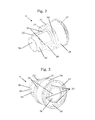
Fig. 2 eine Hülse, welche als Adapterhülse ausgebildet ist, -
Fig. 3 eine weitere Ansicht derFig. 2 , -
Fig. 4 einen Schnitt durch eine Verbindungshülse, -
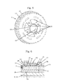
Fig. 5 ein Antriebsrad, welches auf der Adapterhülse gelagert werden kann und -
Fig. 6 einen Schnitt durch die Lagerung des Antriebsrades auf dem Adapterhülse. -
Fig. 1 zeigt einen Nockenwellenversteller 1 und ein Nockenwellenende 5. Der Nockenwellenversteller 1 weist ein Antriebsrad 2, einen Stator 3, einen Rotor 4, eine Scheibe 47, eine Verriegelung 6, eine Rückstellfeder 7 sowie eine Adapterhülse 9 und eine Verbindungshülse 10 auf. Dabei weist die Anordnung weiterhin eine Zentralschraube 8 und eine Abdeckhaube 46 auf. - Der Nockenwellenversteller 1 ist als Flügelzellenversteller ausgebildet, wobei zwischen dem Rotor 4 und dem Stator 3 nicht weiter dargestellte Druckkammern ausgebildet sind, die öldruckbeaufschlagt werden können. Die Zufuhr von Öl erfolgt über das Nockenwellenende 5 durch die Ölbohrungen 18, 19, bzw. durch die Ölbohrungen 20, welche in einen Spalt zwischen dem Schraubenschaft 24 der Zentralschraube 8 und einem Innendurchmesser der zentralen Nockenwellenbohrung 15 mündet. Dabei gelangt das Öl vorerst in die Adapterhülse 9, von der das Öl mittels weiterer Anordnungen von Ölbohrungen und Ölnuten das Innere des Nockenwellenverstellers 1 und zu den Druckkammern geleitet werden kann. Die Ausbildung der Ölleitung durch die Adapterhülse ist in
Fig. 2 und Fig. 3 erläutert. - Auf der Adapterhülse 9 ist das Antriebsrad 2 gelagert. Ein als Umformteil topfförmig ausgebildeter Rotor 4 mit einer integrierten Verriegelung 6 schließt sich in axialer Richtung koaxial zum Antriebsrad 2 und der Scheibe 47 an. Der Rotor 4 wird mit einer Nabe auf dem Adapterteil 9 gelagert. Ein ebenfalls als Umformteil topfförmig ausgebildeter Stator 3 umschließt den Rotor 4 und die Scheibe 47. Die Scheibe 47 dient hier als Dichtelement. Der Stator 3 ist mit seinem einen Ende formschlüssig auf einem Absatz 23 mit dem Antriebsrad 2 zentriert und verbunden, damit eine Übertragung von Drehmomenten des Antriebsrades 2 auf den Stator 3 stattfinden kann. Innerhalb des Rotors 4 und außerhalb der Adapterhülse 9 ist die Rückstellfeder 7 angeordnet. Die Rückstellfeder 7 verspannt den Rotor 4 mit dem Stator 3 rotativ. Abschließend wird die Verbindungshülse 10 mit der Adapterhülse 9 verbunden, so dass der Rotor 4 mit der Verbindungshülse 10 und der Adapterhülse 9 drehfest verspannt ist und zugleich eine axiale Sicherung der ineinandergeschachtelten Bauteile, wie Antriebsrad 2, Stator 3, Rotor 4 erfolgt. Zugleich werden durch den Verbund aus Adapterhülse 9 und Verbindungshülse 10 die Bauteile zentriert. Zwischen Verbindungshülse 10 und Stator 3 besteht in radialer, wie in axialer Richtung geringes Spiel, damit Verformungen aus dem Betrieb nicht zu einem Verklemmen führen.
- Weiterhin zeigt
Fig. 1 , dass der Nockenwellenversteller 1 mittels einer Zentralschraube 8 am Nockenwellenende 5 drehfest befestigt ist. Dabei ist der Nockenwellenversteller 1 mit der Adapterhülse 9 an einer Aufnahme 21 vom Nockenwellenende 5 angeordnet. Die Adapterhülse 9 und die Aufnahme 21 bilden zusammen eine Zentrierung des Nockenwellenverstellers 1. Zusätzlich ist eine Abdeckhaube 46 am Antriebsrad 2 durch eine Schnappverbindung verbunden. Zwischen Abdeckhaube 46 und Stator 3 ist eine Dichtung 12 vorgesehen, die den Nockenwellenversteller öldicht ausbildet. Eine Entlüftung führt durch einen koaxialen in der Zentralschraube 8 ausgebildeten Entlüftungskanal 11 Leckageöl zu einem weiteren Abschnitt der Nockenwellenbohrung 15 zurück zu den Entlüftungsbohrungen 16 in dem Nockenwellenende 5. Dabei trennt ein Gewinde 25 die Nockenwellenbohrung 15 die Entlüftungsbohrungen 16 von der Ölversorgung 20 lokal ab. - Die Montage eines nach
Fig. 1 gezeigten Nockenwellenverstellers 1 kann derart erfolgen, dass zuerst auf die Adapterhülse 9 ein Antriebsrad 2 gefügt wird, gefolgt von der Scheibe 47. Anschließend werden der Rotor 4 mit der Verriegelung 6, der Stator 3 und die Rückstellfeder 7 zueinander gefügt, so dass die Rückstellfeder 7 zwischen dem Stator 3 mit dem Rotor 4 wirken kann und die Verriegelung 6 durch das Verriegeln eine Position von Stator 3 und Rotor 4 definiert. Folglich werden dann Stator 3, Rotor 4, Rückstellfeder 7 und Verriegelung 6 koaxial auf die Adapterhülse 9 aufgeschoben, derart, dass der Rotor 4 auf der Adapterhülse 9 einen axialen Anschlag und eine Zentrierung findet, wobei der Stator 3 auf dem Antriebsrad 2 drehfest zentriert wird. Abschließend wird dieser geschaffene Verbund mit der Verbindungshülse 10 gesichert. Weiterhin kann nun der Nockenwellenversteller 1 durch eine Zentralschraube 8 an einem Nockenwellenende 5 befestigt und gegebenenfalls bei einer Ausbildung eines Zugmitteltriebes ohne Öl mit einer Abdeckhaube 46 öldicht ausgebildet werden. -
Fig. 2 zeigt eine Adapterhülse 9, welche ölführend ausgebildet ist. Das Öl kann durch die eingangs erwähnten, in dieser Figur nicht dargestellten Ölbohrungen 20 von der Zentralbohrung 26 über radiale Ölbohrungen 32 zu einer Ölnut 31 geleitet werden, welche das Öl dann umfangsseitig verteilt und durch weitere nicht dargestellte Kanalausbildungen zwischen Stator und Antriebsrad in eine erste Arbeitskammer geleitet wird. Die Versorgung einer zweiten Arbeitskammer erfolgt durch die eingangs erwähnten Ölbohrungen 18, 19, wobei dann das Öl über Ölbohrungen 33 weitergeleitet wird, welche in die Rückstellfederzentrierung 29 münden. Die Adapterhülse 9 weist eine Zentralbohrung 26 auf, die zur Durchdringung einer Zentralschraube 8 vorgesehen ist. Der axiale Anschlag 27 ist zur Fixierung des Antriebsrades 2 auf dem Lagerdurchmesser 28 vorgesehen. Über die Ölnut 31 kann Öl zur Schmierung der Lagerstelle des Antriebsrades 2 herbeigeführt werden. Weiter weist die Adapterhülse 9 eine Rückstellfederanlage 34 und eine Rückstellfederzentrierung 29 auf. Der axiale Anschlag 35 am verjüngenden Ende der Adapterhülse 9 ist zur Fixierung eines Rotors vorgesehen. Dabei wird der Rotor gegen diesen Anschlag 35 durch die Verbindungshülse 10 kraftschlüssig drehfest verbunden. Die Rotorzentrierung 30 bildet eine fluchtende und koaxiale Anordnung des Rotors zur Drehachse 22. Der Innendurchmesser der Zentralbohrung 26 weist ein nicht weiter dargestelltes Gewinde auf. -
Fig. 3 zeigt eine weitere Ansicht der Adapterhülse 9 und die Mündung der Ölbohrungen 33 in eine axiale stirnseitige Ölnut 36. Die stirnseitige Ölnut 36 wird dabei von dem Anschlag 27 und der Zentralbohrung 26 dichtend begrenzt. Die radialen Ölbohrungen 32 münden innenseitig in die Zentralbohrung 26 und außenseitig in die umlaufende Ölnut 31 auf dem Lagerdurchmesser 28. -
Fig. 4 zeigt eine Hülse, welche als Verbindungshülse 10 ausgebildet ist. Dabei weist die Verbindungshülse 10 ein Gewinde 38 und eine Zentralbohrung 37 auf. Zum Verspannen des Rotors 4 mit der Adapterhülse 9 ist die Ausbildung eines axialen Anschlages vorgesehen, welcher sich radial nach außen erstreckt. Dem schließt sich ein Absatz 40 an, welcher eine spielbehaftete Lagerstelle für einen Stator 3 darstellt. Mittels einem weiteren axialen Anschlag 41 wird der Stator 3 und auch das Antriebsrad 2 in Kombination mit dem inFig. 2 erwähnten Anschlag 27 der Nockenwellenversteller 1 zusammengehalten. Die Nasen 42 bilden eine komplementäre Form zum Eingriff eines Werkzeugs, mit dem die Verbindungshülse 10 montiert werden kann. -
Fig. 5 zeigt eine Ausbildung eines Antriebsrades 2 in Blech. Dabei weist das Antriebsrad 2 eine Zahnkontur 13 für einen Zahnriemen und einen Bord 14 zur Lagefixierung desselben auf. Weiterhin ist an der Zentralbohrung 44 des Antriebsrades 2 eine Nabe 43 angeordnet. Zwischen Nabe 43 und Zahnkontur 13 erstrecken sich umfangsseitig gleichmäßig verteilte Auswölbungen 45, welche sich abwechselnd mit der Ausprägung eines Absatzes 23 in Drehrichtung um die Drehachse 22 anordnen. Über diese Ausprägungen des Absatzes 23 und den Auswölbungen 45 lassen sich Ölkanäle gestalten sowie ein Formschluss zur Übertragung eines Drehmomentes zwischen Stator und Antriebsrad realisieren. -
Fig. 6 zeigt eine Detailansicht des Antriebsrades 2 mit seiner Zentralbohrung 44 der Nabe 43 auf dem Lagerdurchmesser 28 der Adapterhülse 9. Bei der Montage des Nockenwellenverstellers 1 mit dem Nockenwellenende 5 wird der als Stufe ausgebildete Anschlag 27 von der Aufnahme 21 umfasst, derart, dass eine Zentrierung über die Durchmesser dieser Lagerstelle, eine Ölversorgung und eine flächige Anlage realisiert wird. -
- 1)
- Nockenwellenversteller
- 2)
- Antriebsrad
- 3)
- Stator
- 4)
- Rotor
- 5)
- Nockenwellenende
- 6)
- Verriegelung
- 7)
- Rückstellfeder
- 8)
- Zentralschraube
- 9)
- Adapterhülse
- 10)
- Verbindungshülse
- 11)
- Entlüftungskanal
- 12)
- Dichtung
- 13)
- Zahnkontur
- 14)
- Bord
- 15)
- Nockenwellenbohrung
- 16)
- Entlüftungsbohrungen
- 17)
- Axiallager
- 18)
- Ölbohrung
- 19)
- Ölbohrung
- 20)
- Ölbohrung
- 21)
- Aufnahme
- 22)
- Drehachse
- 23)
- Absatz
- 24)
- Schraubenschaft
- 25)
- Gewinde
- 26)
- Zentralbohrung
- 27)
- Anschlag
- 28)
- Lagerdurchmesser
- 29)
- Rückstellfederzentrierung
- 30)
- Rotorzentrierung
- 31)
- radiale Ölnut
- 32)
- Ölbohrungen
- 33)
- Ölbohrungen
- 34)
- Rückstellfederanlage
- 35)
- axialer Anschlag
- 36)
- Ölnut
- 37)
- Zentralbohrung
- 38)
- Gewinde
- 39)
- axialer Anschlag
- 40)
- Absatz
- 41)
- axialer Anschlag
- 42)
- Nasen
- 43)
- Nabe
- 44)
- Zentralbohrung
- 45)
- Auswölbungen
- 46)
- Abdeckhaube
- 47)
- Scheibe
Claims (10)
- Nockenwellenversteller (1), welcher ein Antriebsrad (2), einen Stator (3) und einen Rotor (4) aufweist, wobei der Rotor (4) gegenüber dem Stator (3) einen Drehfreiheitsgrad besitzt und der Rotor (4) gegenüber dem Stator (3) axial fixiert ist, dadurch gekennzeichnet, dass der Nockenwellenversteller (1) zur Drehachse (22) des Antriebsrades (2) koaxial angeordnet eine Adapterhülse (9) und eine Verbindungshülse (10) aufweist, wobei die Adapterhülse (9) und die Verbindungshülse (10) einerseits untereinander verbunden sind und andererseits eine axiale Fixierung von Rotor (4), Stator (3) und Antriebsrad (2) ausbilden.
- Nockenwellenversteller (1) nach Anspruch 1, dadurch gekennzeichnet, dass die Adapterhülse (9) mit einem Nockenwellenende (5) verbindbar ist.
- Nockenwellenversteller (1) nach Anspruch 1, dadurch gekennzeichnet, dass die Adapterhülse (9) ölführend ausgebildet ist.
- Nockenwellenversteller (1) nach Anspruch 1, dadurch gekennzeichnet, dass die Adapterhülse (9) einen axialen Anschlag (27) zur Fixierung eines Antriebsrades (2) aufweist.
- Nockenwellenversteller (1) nach Anspruch 1, dadurch gekennzeichnet, dass die Adapterhülse (9) und die Verbindungshülse (10) jeweils einen axialen Anschlag (35, 39) zur Fixierung eines Rotors (4) aufweisen.
- Nockenwellenversteller (1) nach Anspruch 1, dadurch gekennzeichnet, dass die Verbindungshülse (10) einen axialen Anschlag (41) zur Fixierung eines Stators (3) aufweist.
- Nockenwellenversteller (1) nach Anspruch 1, dadurch gekennzeichnet, dass auf der Adapterhülse (9) ein Antriebsrad (2) gelagert ist.
- Nockenwellenversteller (1) nach Anspruch 1, dadurch gekennzeichnet, dass die Adapterhülse (9) oder die Verbindungshülse (10) ein Gewinde aufweist.
- Nockenwellenversteller (1) nach Anspruch 1, dadurch gekennzeichnet, dass die Adapterhülse (9) mit der Verbindungshülse (10) eine Übermaßverbindung aufweist.
- Nockenwellenversteller (1) nach Anspruch 1, dadurch gekennzeichnet, dass das Abtriebsrad (2) einen Absatz (23) aufweist, mit dessen Durchmesser der Stator (3) zentriert wird und ein Drehmoment übertragen wird.
Applications Claiming Priority (1)
| Application Number | Priority Date | Filing Date | Title |
|---|---|---|---|
| DE102010063703A DE102010063703A1 (de) | 2010-12-21 | 2010-12-21 | Nockenwellenversteller |
Publications (3)
| Publication Number | Publication Date |
|---|---|
| EP2469048A2 true EP2469048A2 (de) | 2012-06-27 |
| EP2469048A3 EP2469048A3 (de) | 2013-01-23 |
| EP2469048B1 EP2469048B1 (de) | 2013-11-13 |
Family
ID=44883086
Family Applications (1)
| Application Number | Title | Priority Date | Filing Date |
|---|---|---|---|
| EP11181846.4A Not-in-force EP2469048B1 (de) | 2010-12-21 | 2011-09-19 | Nockenwellenversteller |
Country Status (3)
| Country | Link |
|---|---|
| US (1) | US20120152188A1 (de) |
| EP (1) | EP2469048B1 (de) |
| DE (1) | DE102010063703A1 (de) |
Cited By (4)
| Publication number | Priority date | Publication date | Assignee | Title |
|---|---|---|---|---|
| WO2014131381A1 (de) * | 2013-02-27 | 2014-09-04 | Schaeffler Technologies AG & Co. KG | Nockenwellenversteller |
| DE102014200462A1 (de) | 2014-01-14 | 2015-01-08 | Schaeffler Technologies Gmbh & Co. Kg | Nockenwellenversteller |
| WO2015090296A1 (de) * | 2013-12-18 | 2015-06-25 | Schaeffler Technologies AG & Co. KG | Aufbauprinzip eines geteilten rotors für einen hydraulischen nockenwellenversteller |
| WO2019001620A1 (de) * | 2017-06-27 | 2019-01-03 | Schaeffler Technologies AG & Co. KG | Nockenwellenversteller mit einem stator und einem rotor mit zu diesem konzentrischer federaufnahme |
Families Citing this family (10)
| Publication number | Priority date | Publication date | Assignee | Title |
|---|---|---|---|---|
| DE102015204755A1 (de) | 2015-03-17 | 2016-09-22 | Schaeffler Technologies AG & Co. KG | Verfahren zum Herstellen eines Antriebsrades für einen Nockenwellenversteller und Antriebsrad für einen Nockenwellenversteller |
| DE102016207177B3 (de) * | 2016-04-27 | 2017-10-19 | Schaeffler Technologies AG & Co. KG | Nockenwellenversteller mit einer axial gewickelten Drehfeder und einem umgeformten, federführenden und druckmitteldichten Blechfederdeckel |
| CN209195497U (zh) * | 2016-06-09 | 2019-08-02 | 三菱电机株式会社 | 阀正时调节装置 |
| DE102016213797A1 (de) * | 2016-07-27 | 2017-07-20 | Schaeffler Technologies AG & Co. KG | Nockenwellenversteller |
| KR102322288B1 (ko) * | 2017-06-29 | 2021-11-05 | 현대자동차주식회사 | 원웨이 클러치 방식 가변밸브타이밍 기구 및 엔진 시스템 |
| DE112018008008T5 (de) * | 2018-09-25 | 2021-06-17 | Schaeffler Technologies AG & Co. KG | Einsatz für einen Nockenwellenversteller sowie Nockenwellenversteller |
| DE102019103161A1 (de) * | 2019-02-08 | 2020-08-13 | ECO Holding 1 GmbH | Nockenwellenversteller und Verfahren zur Montage eines Nockenwellenverstellers |
| CN110513444B (zh) * | 2019-09-03 | 2024-09-24 | 绵阳富临精工机械股份有限公司 | 一种相位器润滑油路系统 |
| DE102020202647A1 (de) | 2020-03-02 | 2021-09-02 | Psa Automobiles Sa | Mit einer Nockenwelle verschraubter Rotor einer Nockenwellenverstellung, bei welcher ein Gewinde der Verschraubung entgegengesetzt zu einer Rotationsrichtung der Nockenwelle angeordnet ist |
| CN116423448B (zh) * | 2023-05-31 | 2025-07-15 | 广西玉柴机器股份有限公司 | 一种用于加工中心蜗杆安装导向工具 |
Citations (1)
| Publication number | Priority date | Publication date | Assignee | Title |
|---|---|---|---|---|
| DE102008029692A1 (de) | 2008-06-24 | 2010-01-07 | Hydraulik-Ring Gmbh | Gebaute Nockenwelle mit einem Flügelzellenversteller und Herstellungsverfahren |
Family Cites Families (15)
| Publication number | Priority date | Publication date | Assignee | Title |
|---|---|---|---|---|
| JP2833128B2 (ja) * | 1990-03-29 | 1998-12-09 | アイシン精機株式会社 | 弁開閉時期制御装置 |
| JPH06221120A (ja) * | 1993-01-29 | 1994-08-09 | Aisin Seiki Co Ltd | 弁開閉時期制御装置 |
| JP3014893B2 (ja) * | 1993-05-19 | 2000-02-28 | 株式会社デンソー | バルブタイミング調整装置 |
| JP3671440B2 (ja) * | 1994-09-16 | 2005-07-13 | 株式会社デンソー | トルク伝達装置 |
| DE19817319C2 (de) * | 1998-04-18 | 2001-12-06 | Daimler Chrysler Ag | Nockenwellenversteller für Brennkraftmaschinen |
| DE10054797A1 (de) * | 2000-11-04 | 2002-05-08 | Ina Schaeffler Kg | Verfahren und Vorrichtung zur Drehwinkelverstellung einer Welle gegenüber ihrem Antrieb |
| JP3937164B2 (ja) * | 2002-04-19 | 2007-06-27 | 株式会社デンソー | バルブタイミング調整装置 |
| DE10223431B4 (de) * | 2002-05-25 | 2004-07-08 | Ina-Schaeffler Kg | Brennkraftmaschine mit zumindest zwei nebeneinander angeordneten, jeweils mit einer Vorrichtung zur Drehwinkelverstellung gegenüber einer Kurbelwelle ausgebildeten Nockenwellen |
| DE10359068A1 (de) * | 2003-12-16 | 2005-07-21 | Ina-Schaeffler Kg | Brennkraftmaschine mit einer hydraulischen Vorrichtung zur Drehwinkelverstellung einer Nockenwelle gegenüber einer Kurbelwelle |
| JP2008002324A (ja) * | 2006-06-21 | 2008-01-10 | Hitachi Ltd | 位相角検出装置及び該位相角検出装置を用いた内燃機関のバルブタイミング制御装置 |
| US7841311B2 (en) * | 2008-01-04 | 2010-11-30 | Hilite International Inc. | Variable valve timing device |
| JP2009222036A (ja) * | 2008-03-19 | 2009-10-01 | Hitachi Ltd | 内燃機関のバルブタイミング制御装置 |
| DE102009042215B4 (de) * | 2008-10-14 | 2018-06-07 | Schaeffler Technologies AG & Co. KG | Nockenwellenversteller für eine konzentrische Nockenwelle |
| DE102008057491A1 (de) * | 2008-11-15 | 2010-05-20 | Daimler Ag | Nockenwellenverstellvorrichtung |
| JP5440853B2 (ja) * | 2010-01-08 | 2014-03-12 | アイシン精機株式会社 | 弁開閉時期制御装置 |
-
2010
- 2010-12-21 DE DE102010063703A patent/DE102010063703A1/de not_active Withdrawn
-
2011
- 2011-09-19 EP EP11181846.4A patent/EP2469048B1/de not_active Not-in-force
- 2011-12-20 US US13/331,054 patent/US20120152188A1/en not_active Abandoned
Patent Citations (1)
| Publication number | Priority date | Publication date | Assignee | Title |
|---|---|---|---|---|
| DE102008029692A1 (de) | 2008-06-24 | 2010-01-07 | Hydraulik-Ring Gmbh | Gebaute Nockenwelle mit einem Flügelzellenversteller und Herstellungsverfahren |
Cited By (4)
| Publication number | Priority date | Publication date | Assignee | Title |
|---|---|---|---|---|
| WO2014131381A1 (de) * | 2013-02-27 | 2014-09-04 | Schaeffler Technologies AG & Co. KG | Nockenwellenversteller |
| WO2015090296A1 (de) * | 2013-12-18 | 2015-06-25 | Schaeffler Technologies AG & Co. KG | Aufbauprinzip eines geteilten rotors für einen hydraulischen nockenwellenversteller |
| DE102014200462A1 (de) | 2014-01-14 | 2015-01-08 | Schaeffler Technologies Gmbh & Co. Kg | Nockenwellenversteller |
| WO2019001620A1 (de) * | 2017-06-27 | 2019-01-03 | Schaeffler Technologies AG & Co. KG | Nockenwellenversteller mit einem stator und einem rotor mit zu diesem konzentrischer federaufnahme |
Also Published As
| Publication number | Publication date |
|---|---|
| EP2469048B1 (de) | 2013-11-13 |
| DE102010063703A1 (de) | 2012-06-21 |
| EP2469048A3 (de) | 2013-01-23 |
| US20120152188A1 (en) | 2012-06-21 |
Similar Documents
| Publication | Publication Date | Title |
|---|---|---|
| EP2469048B1 (de) | Nockenwellenversteller | |
| EP1573176B1 (de) | Brennkraftmaschine mit einer vorrichtung zur hydraulischen drehwinkelverstellung ihrer nockenwelle gegen ber ihrer kurbelwelle sowie mit einer vakuumpumpe für einen servoverbraucher, insbesondere für einen bremskraftverstärker | |
| DE102015200139B4 (de) | Nockenwellenverstelleranbindung an eine Doppelnockenwelle | |
| DE102011001301A1 (de) | Schwenkmotorversteller | |
| DE102008029692B4 (de) | Gebaute Nockenwelle mit einem Flügelzellenversteller und Herstellungsverfahren | |
| EP2299071B1 (de) | Vorrichtung zur Veränderung einer relativen Drehwinkellage einer Nockenwelle gegenüber einer Kurbelwelle einer Brennkraftmaschine | |
| WO2011134751A1 (de) | Nockenwellenverstellsystem für eine brennkraftmaschine | |
| DE102008050134A1 (de) | Einrichtung zur Nockenwellenverstellung für Verbrennungskraftmaschinen | |
| DE102013018775A1 (de) | Triebstock-Getriebeeinrichtung | |
| DE102012204726A1 (de) | Nockenwellenversteller | |
| WO2013174533A1 (de) | Steuerventil eines nockenwellenverstellers | |
| DE102008032949B4 (de) | Vorrichtung zur variablen Einstellung der Steuerzeiten von Gaswechselventilen einer Brennkraftmaschine | |
| DE102012202823A1 (de) | Nockenwellenversteller | |
| DE102015205770B4 (de) | Nockenwellenbaugruppe | |
| DE102015214623A1 (de) | Nockenwellenverstellvorrichtung | |
| DE102012208495B4 (de) | Nockenwellenversteller | |
| DE102011000822B4 (de) | Gehäuse mit einem Schwenkmotorversteller | |
| DE102015205272A1 (de) | Nockenwellenversteller mit Oldham-Kupplung zur Anbindung an eine Nockenwelle | |
| DE102015202372A1 (de) | Nockenwellenversteller | |
| DE102014209312A1 (de) | Nockenwellenverstellanordnung, umfassend axialer Sicherung mittels Spannhülse | |
| DE102013204659A1 (de) | Nockenwellenversteller | |
| DE102007023617B4 (de) | Nockenwellenversteller | |
| WO2017071700A1 (de) | Nockenwellenverstellvorrichtung | |
| DE102012210016A1 (de) | Nockenwellenverstelleranordnung | |
| DE102018115167B4 (de) | Nockenwellenverstellvorrichtung mit einem kompakten Aufbau für einen trockenen Riementrieb einer Brennkraftmaschine und Montageverfahren der Nockenwellenverstellvorrichtung |
Legal Events
| Date | Code | Title | Description |
|---|---|---|---|
| 17P | Request for examination filed |
Effective date: 20110919 |
|
| AK | Designated contracting states |
Kind code of ref document: A2 Designated state(s): AL AT BE BG CH CY CZ DE DK EE ES FI FR GB GR HR HU IE IS IT LI LT LU LV MC MK MT NL NO PL PT RO RS SE SI SK SM TR |
|
| AX | Request for extension of the european patent |
Extension state: BA ME |
|
| PUAI | Public reference made under article 153(3) epc to a published international application that has entered the european phase |
Free format text: ORIGINAL CODE: 0009012 |
|
| PUAL | Search report despatched |
Free format text: ORIGINAL CODE: 0009013 |
|
| AK | Designated contracting states |
Kind code of ref document: A3 Designated state(s): AL AT BE BG CH CY CZ DE DK EE ES FI FR GB GR HR HU IE IS IT LI LT LU LV MC MK MT NL NO PL PT RO RS SE SI SK SM TR |
|
| AX | Request for extension of the european patent |
Extension state: BA ME |
|
| RIC1 | Information provided on ipc code assigned before grant |
Ipc: F01L 1/344 20060101AFI20121214BHEP |
|
| GRAP | Despatch of communication of intention to grant a patent |
Free format text: ORIGINAL CODE: EPIDOSNIGR1 |
|
| INTG | Intention to grant announced |
Effective date: 20130607 |
|
| GRAS | Grant fee paid |
Free format text: ORIGINAL CODE: EPIDOSNIGR3 |
|
| RBV | Designated contracting states (corrected) |
Designated state(s): AL AT BE BG CH CY CZ DE DK EE ES FI FR GB GR HR HU IE IS IT LI LT LU LV MC MK MT NL NO PL PT RO RS SE SI SK SM TR |
|
| GRAA | (expected) grant |
Free format text: ORIGINAL CODE: 0009210 |
|
| AK | Designated contracting states |
Kind code of ref document: B1 Designated state(s): AL AT BE BG CH CY CZ DE DK EE ES FI FR GB GR HR HU IE IS IT LI LT LU LV MC MK MT NL NO PL PT RO RS SE SI SK SM TR |
|
| REG | Reference to a national code |
Ref country code: GB Ref legal event code: FG4D Free format text: NOT ENGLISH |
|
| REG | Reference to a national code |
Ref country code: CH Ref legal event code: EP |
|
| REG | Reference to a national code |
Ref country code: AT Ref legal event code: REF Ref document number: 640677 Country of ref document: AT Kind code of ref document: T Effective date: 20131215 |
|
| REG | Reference to a national code |
Ref country code: IE Ref legal event code: FG4D Free format text: LANGUAGE OF EP DOCUMENT: GERMAN |
|
| REG | Reference to a national code |
Ref country code: DE Ref legal event code: R096 Ref document number: 502011001606 Country of ref document: DE Effective date: 20140109 |
|
| REG | Reference to a national code |
Ref country code: NL Ref legal event code: VDEP Effective date: 20131113 |
|
| RAP2 | Party data changed (patent owner data changed or rights of a patent transferred) |
Owner name: SCHAEFFLER TECHNOLOGIES GMBH & CO. KG |
|
| REG | Reference to a national code |
Ref country code: DE Ref legal event code: R081 Ref document number: 502011001606 Country of ref document: DE Owner name: SCHAEFFLER TECHNOLOGIES AG & CO. KG, DE Free format text: FORMER OWNER: SCHAEFFLER TECHNOLOGIES AG & CO. KG, 91074 HERZOGENAURACH, DE Effective date: 20140218 Ref country code: DE Ref legal event code: R081 Ref document number: 502011001606 Country of ref document: DE Owner name: SCHAEFFLER TECHNOLOGIES GMBH & CO. KG, DE Free format text: FORMER OWNER: SCHAEFFLER TECHNOLOGIES AG & CO. KG, 91074 HERZOGENAURACH, DE Effective date: 20140218 |
|
| REG | Reference to a national code |
Ref country code: LT Ref legal event code: MG4D |
|
| PG25 | Lapsed in a contracting state [announced via postgrant information from national office to epo] |
Ref country code: IS Free format text: LAPSE BECAUSE OF FAILURE TO SUBMIT A TRANSLATION OF THE DESCRIPTION OR TO PAY THE FEE WITHIN THE PRESCRIBED TIME-LIMIT Effective date: 20140313 Ref country code: NO Free format text: LAPSE BECAUSE OF FAILURE TO SUBMIT A TRANSLATION OF THE DESCRIPTION OR TO PAY THE FEE WITHIN THE PRESCRIBED TIME-LIMIT Effective date: 20140213 Ref country code: FI Free format text: LAPSE BECAUSE OF FAILURE TO SUBMIT A TRANSLATION OF THE DESCRIPTION OR TO PAY THE FEE WITHIN THE PRESCRIBED TIME-LIMIT Effective date: 20131113 Ref country code: HR Free format text: LAPSE BECAUSE OF FAILURE TO SUBMIT A TRANSLATION OF THE DESCRIPTION OR TO PAY THE FEE WITHIN THE PRESCRIBED TIME-LIMIT Effective date: 20131113 Ref country code: NL Free format text: LAPSE BECAUSE OF FAILURE TO SUBMIT A TRANSLATION OF THE DESCRIPTION OR TO PAY THE FEE WITHIN THE PRESCRIBED TIME-LIMIT Effective date: 20131113 Ref country code: SE Free format text: LAPSE BECAUSE OF FAILURE TO SUBMIT A TRANSLATION OF THE DESCRIPTION OR TO PAY THE FEE WITHIN THE PRESCRIBED TIME-LIMIT Effective date: 20131113 Ref country code: LT Free format text: LAPSE BECAUSE OF FAILURE TO SUBMIT A TRANSLATION OF THE DESCRIPTION OR TO PAY THE FEE WITHIN THE PRESCRIBED TIME-LIMIT Effective date: 20131113 |
|
| PG25 | Lapsed in a contracting state [announced via postgrant information from national office to epo] |
Ref country code: CY Free format text: LAPSE BECAUSE OF FAILURE TO SUBMIT A TRANSLATION OF THE DESCRIPTION OR TO PAY THE FEE WITHIN THE PRESCRIBED TIME-LIMIT Effective date: 20131113 Ref country code: RS Free format text: LAPSE BECAUSE OF FAILURE TO SUBMIT A TRANSLATION OF THE DESCRIPTION OR TO PAY THE FEE WITHIN THE PRESCRIBED TIME-LIMIT Effective date: 20131113 Ref country code: LV Free format text: LAPSE BECAUSE OF FAILURE TO SUBMIT A TRANSLATION OF THE DESCRIPTION OR TO PAY THE FEE WITHIN THE PRESCRIBED TIME-LIMIT Effective date: 20131113 Ref country code: ES Free format text: LAPSE BECAUSE OF FAILURE TO SUBMIT A TRANSLATION OF THE DESCRIPTION OR TO PAY THE FEE WITHIN THE PRESCRIBED TIME-LIMIT Effective date: 20131113 |
|
| PG25 | Lapsed in a contracting state [announced via postgrant information from national office to epo] |
Ref country code: PT Free format text: LAPSE BECAUSE OF FAILURE TO SUBMIT A TRANSLATION OF THE DESCRIPTION OR TO PAY THE FEE WITHIN THE PRESCRIBED TIME-LIMIT Effective date: 20140313 |
|
| PG25 | Lapsed in a contracting state [announced via postgrant information from national office to epo] |
Ref country code: EE Free format text: LAPSE BECAUSE OF FAILURE TO SUBMIT A TRANSLATION OF THE DESCRIPTION OR TO PAY THE FEE WITHIN THE PRESCRIBED TIME-LIMIT Effective date: 20131113 |
|
| REG | Reference to a national code |
Ref country code: DE Ref legal event code: R097 Ref document number: 502011001606 Country of ref document: DE |
|
| PG25 | Lapsed in a contracting state [announced via postgrant information from national office to epo] |
Ref country code: PL Free format text: LAPSE BECAUSE OF FAILURE TO SUBMIT A TRANSLATION OF THE DESCRIPTION OR TO PAY THE FEE WITHIN THE PRESCRIBED TIME-LIMIT Effective date: 20131113 Ref country code: SK Free format text: LAPSE BECAUSE OF FAILURE TO SUBMIT A TRANSLATION OF THE DESCRIPTION OR TO PAY THE FEE WITHIN THE PRESCRIBED TIME-LIMIT Effective date: 20131113 Ref country code: RO Free format text: LAPSE BECAUSE OF FAILURE TO SUBMIT A TRANSLATION OF THE DESCRIPTION OR TO PAY THE FEE WITHIN THE PRESCRIBED TIME-LIMIT Effective date: 20131113 Ref country code: CZ Free format text: LAPSE BECAUSE OF FAILURE TO SUBMIT A TRANSLATION OF THE DESCRIPTION OR TO PAY THE FEE WITHIN THE PRESCRIBED TIME-LIMIT Effective date: 20131113 |
|
| PLBE | No opposition filed within time limit |
Free format text: ORIGINAL CODE: 0009261 |
|
| STAA | Information on the status of an ep patent application or granted ep patent |
Free format text: STATUS: NO OPPOSITION FILED WITHIN TIME LIMIT |
|
| PG25 | Lapsed in a contracting state [announced via postgrant information from national office to epo] |
Ref country code: DK Free format text: LAPSE BECAUSE OF FAILURE TO SUBMIT A TRANSLATION OF THE DESCRIPTION OR TO PAY THE FEE WITHIN THE PRESCRIBED TIME-LIMIT Effective date: 20131113 |
|
| 26N | No opposition filed |
Effective date: 20140814 |
|
| REG | Reference to a national code |
Ref country code: DE Ref legal event code: R097 Ref document number: 502011001606 Country of ref document: DE Effective date: 20140814 |
|
| PG25 | Lapsed in a contracting state [announced via postgrant information from national office to epo] |
Ref country code: SI Free format text: LAPSE BECAUSE OF FAILURE TO SUBMIT A TRANSLATION OF THE DESCRIPTION OR TO PAY THE FEE WITHIN THE PRESCRIBED TIME-LIMIT Effective date: 20131113 |
|
| PG25 | Lapsed in a contracting state [announced via postgrant information from national office to epo] |
Ref country code: LU Free format text: LAPSE BECAUSE OF FAILURE TO SUBMIT A TRANSLATION OF THE DESCRIPTION OR TO PAY THE FEE WITHIN THE PRESCRIBED TIME-LIMIT Effective date: 20140919 Ref country code: MC Free format text: LAPSE BECAUSE OF FAILURE TO SUBMIT A TRANSLATION OF THE DESCRIPTION OR TO PAY THE FEE WITHIN THE PRESCRIBED TIME-LIMIT Effective date: 20131113 |
|
| REG | Reference to a national code |
Ref country code: CH Ref legal event code: PL |
|
| REG | Reference to a national code |
Ref country code: DE Ref legal event code: R081 Ref document number: 502011001606 Country of ref document: DE Owner name: SCHAEFFLER TECHNOLOGIES AG & CO. KG, DE Free format text: FORMER OWNER: SCHAEFFLER TECHNOLOGIES GMBH & CO. KG, 91074 HERZOGENAURACH, DE Effective date: 20150407 |
|
| REG | Reference to a national code |
Ref country code: IE Ref legal event code: MM4A |
|
| REG | Reference to a national code |
Ref country code: FR Ref legal event code: ST Effective date: 20150529 |
|
| PG25 | Lapsed in a contracting state [announced via postgrant information from national office to epo] |
Ref country code: BE Free format text: LAPSE BECAUSE OF NON-PAYMENT OF DUE FEES Effective date: 20140930 |
|
| PG25 | Lapsed in a contracting state [announced via postgrant information from national office to epo] |
Ref country code: LI Free format text: LAPSE BECAUSE OF NON-PAYMENT OF DUE FEES Effective date: 20140930 Ref country code: CH Free format text: LAPSE BECAUSE OF NON-PAYMENT OF DUE FEES Effective date: 20140930 |
|
| PG25 | Lapsed in a contracting state [announced via postgrant information from national office to epo] |
Ref country code: IE Free format text: LAPSE BECAUSE OF NON-PAYMENT OF DUE FEES Effective date: 20140919 Ref country code: FR Free format text: LAPSE BECAUSE OF NON-PAYMENT OF DUE FEES Effective date: 20140930 Ref country code: IT Free format text: LAPSE BECAUSE OF FAILURE TO SUBMIT A TRANSLATION OF THE DESCRIPTION OR TO PAY THE FEE WITHIN THE PRESCRIBED TIME-LIMIT Effective date: 20131113 |
|
| PG25 | Lapsed in a contracting state [announced via postgrant information from national office to epo] |
Ref country code: SM Free format text: LAPSE BECAUSE OF FAILURE TO SUBMIT A TRANSLATION OF THE DESCRIPTION OR TO PAY THE FEE WITHIN THE PRESCRIBED TIME-LIMIT Effective date: 20131113 |
|
| GBPC | Gb: european patent ceased through non-payment of renewal fee |
Effective date: 20150919 |
|
| PG25 | Lapsed in a contracting state [announced via postgrant information from national office to epo] |
Ref country code: BG Free format text: LAPSE BECAUSE OF FAILURE TO SUBMIT A TRANSLATION OF THE DESCRIPTION OR TO PAY THE FEE WITHIN THE PRESCRIBED TIME-LIMIT Effective date: 20131113 Ref country code: GR Free format text: LAPSE BECAUSE OF FAILURE TO SUBMIT A TRANSLATION OF THE DESCRIPTION OR TO PAY THE FEE WITHIN THE PRESCRIBED TIME-LIMIT Effective date: 20140214 Ref country code: MT Free format text: LAPSE BECAUSE OF FAILURE TO SUBMIT A TRANSLATION OF THE DESCRIPTION OR TO PAY THE FEE WITHIN THE PRESCRIBED TIME-LIMIT Effective date: 20131113 |
|
| PG25 | Lapsed in a contracting state [announced via postgrant information from national office to epo] |
Ref country code: GB Free format text: LAPSE BECAUSE OF NON-PAYMENT OF DUE FEES Effective date: 20150919 Ref country code: HU Free format text: LAPSE BECAUSE OF FAILURE TO SUBMIT A TRANSLATION OF THE DESCRIPTION OR TO PAY THE FEE WITHIN THE PRESCRIBED TIME-LIMIT; INVALID AB INITIO Effective date: 20110919 Ref country code: TR Free format text: LAPSE BECAUSE OF FAILURE TO SUBMIT A TRANSLATION OF THE DESCRIPTION OR TO PAY THE FEE WITHIN THE PRESCRIBED TIME-LIMIT Effective date: 20131113 |
|
| REG | Reference to a national code |
Ref country code: AT Ref legal event code: MM01 Ref document number: 640677 Country of ref document: AT Kind code of ref document: T Effective date: 20160919 |
|
| PG25 | Lapsed in a contracting state [announced via postgrant information from national office to epo] |
Ref country code: AT Free format text: LAPSE BECAUSE OF NON-PAYMENT OF DUE FEES Effective date: 20160919 |
|
| PG25 | Lapsed in a contracting state [announced via postgrant information from national office to epo] |
Ref country code: MK Free format text: LAPSE BECAUSE OF FAILURE TO SUBMIT A TRANSLATION OF THE DESCRIPTION OR TO PAY THE FEE WITHIN THE PRESCRIBED TIME-LIMIT Effective date: 20131113 |
|
| PG25 | Lapsed in a contracting state [announced via postgrant information from national office to epo] |
Ref country code: AL Free format text: LAPSE BECAUSE OF FAILURE TO SUBMIT A TRANSLATION OF THE DESCRIPTION OR TO PAY THE FEE WITHIN THE PRESCRIBED TIME-LIMIT Effective date: 20131113 |
|
| PGFP | Annual fee paid to national office [announced via postgrant information from national office to epo] |
Ref country code: DE Payment date: 20211118 Year of fee payment: 11 |
|
| REG | Reference to a national code |
Ref country code: DE Ref legal event code: R119 Ref document number: 502011001606 Country of ref document: DE |
|
| P01 | Opt-out of the competence of the unified patent court (upc) registered |
Effective date: 20230522 |
|
| PG25 | Lapsed in a contracting state [announced via postgrant information from national office to epo] |
Ref country code: DE Free format text: LAPSE BECAUSE OF NON-PAYMENT OF DUE FEES Effective date: 20230401 |