EP2468559A2 - Einrichtung zur Entlüftung und Belüftung eines Kraftstofftanks - Google Patents
Einrichtung zur Entlüftung und Belüftung eines Kraftstofftanks Download PDFInfo
- Publication number
- EP2468559A2 EP2468559A2 EP20110009835 EP11009835A EP2468559A2 EP 2468559 A2 EP2468559 A2 EP 2468559A2 EP 20110009835 EP20110009835 EP 20110009835 EP 11009835 A EP11009835 A EP 11009835A EP 2468559 A2 EP2468559 A2 EP 2468559A2
- Authority
- EP
- European Patent Office
- Prior art keywords
- valve unit
- valve
- tank
- fuel tank
- connections
- Prior art date
- Legal status (The legal status is an assumption and is not a legal conclusion. Google has not performed a legal analysis and makes no representation as to the accuracy of the status listed.)
- Withdrawn
Links
Images


Classifications
-
- B—PERFORMING OPERATIONS; TRANSPORTING
- B60—VEHICLES IN GENERAL
- B60K—ARRANGEMENT OR MOUNTING OF PROPULSION UNITS OR OF TRANSMISSIONS IN VEHICLES; ARRANGEMENT OR MOUNTING OF PLURAL DIVERSE PRIME-MOVERS IN VEHICLES; AUXILIARY DRIVES FOR VEHICLES; INSTRUMENTATION OR DASHBOARDS FOR VEHICLES; ARRANGEMENTS IN CONNECTION WITH COOLING, AIR INTAKE, GAS EXHAUST OR FUEL SUPPLY OF PROPULSION UNITS IN VEHICLES
- B60K15/00—Arrangement in connection with fuel supply of combustion engines or other fuel consuming energy converters, e.g. fuel cells; Mounting or construction of fuel tanks
- B60K15/03—Fuel tanks
- B60K15/035—Fuel tanks characterised by venting means
- B60K15/03519—Valve arrangements in the vent line
-
- F—MECHANICAL ENGINEERING; LIGHTING; HEATING; WEAPONS; BLASTING
- F02—COMBUSTION ENGINES; HOT-GAS OR COMBUSTION-PRODUCT ENGINE PLANTS
- F02M—SUPPLYING COMBUSTION ENGINES IN GENERAL WITH COMBUSTIBLE MIXTURES OR CONSTITUENTS THEREOF
- F02M25/00—Engine-pertinent apparatus for adding non-fuel substances or small quantities of secondary fuel to combustion-air, main fuel or fuel-air mixture
- F02M25/08—Engine-pertinent apparatus for adding non-fuel substances or small quantities of secondary fuel to combustion-air, main fuel or fuel-air mixture adding fuel vapours drawn from engine fuel reservoir
- F02M25/0836—Arrangement of valves controlling the admission of fuel vapour to an engine, e.g. valve being disposed between fuel tank or absorption canister and intake manifold
-
- B—PERFORMING OPERATIONS; TRANSPORTING
- B60—VEHICLES IN GENERAL
- B60K—ARRANGEMENT OR MOUNTING OF PROPULSION UNITS OR OF TRANSMISSIONS IN VEHICLES; ARRANGEMENT OR MOUNTING OF PLURAL DIVERSE PRIME-MOVERS IN VEHICLES; AUXILIARY DRIVES FOR VEHICLES; INSTRUMENTATION OR DASHBOARDS FOR VEHICLES; ARRANGEMENTS IN CONNECTION WITH COOLING, AIR INTAKE, GAS EXHAUST OR FUEL SUPPLY OF PROPULSION UNITS IN VEHICLES
- B60K15/00—Arrangement in connection with fuel supply of combustion engines or other fuel consuming energy converters, e.g. fuel cells; Mounting or construction of fuel tanks
- B60K15/03—Fuel tanks
- B60K2015/03256—Fuel tanks characterised by special valves, the mounting thereof
- B60K2015/03276—Valves with membranes
-
- B—PERFORMING OPERATIONS; TRANSPORTING
- B60—VEHICLES IN GENERAL
- B60K—ARRANGEMENT OR MOUNTING OF PROPULSION UNITS OR OF TRANSMISSIONS IN VEHICLES; ARRANGEMENT OR MOUNTING OF PLURAL DIVERSE PRIME-MOVERS IN VEHICLES; AUXILIARY DRIVES FOR VEHICLES; INSTRUMENTATION OR DASHBOARDS FOR VEHICLES; ARRANGEMENTS IN CONNECTION WITH COOLING, AIR INTAKE, GAS EXHAUST OR FUEL SUPPLY OF PROPULSION UNITS IN VEHICLES
- B60K15/00—Arrangement in connection with fuel supply of combustion engines or other fuel consuming energy converters, e.g. fuel cells; Mounting or construction of fuel tanks
- B60K15/03—Fuel tanks
- B60K2015/03256—Fuel tanks characterised by special valves, the mounting thereof
- B60K2015/03302—Electromagnetic valves
-
- B—PERFORMING OPERATIONS; TRANSPORTING
- B60—VEHICLES IN GENERAL
- B60K—ARRANGEMENT OR MOUNTING OF PROPULSION UNITS OR OF TRANSMISSIONS IN VEHICLES; ARRANGEMENT OR MOUNTING OF PLURAL DIVERSE PRIME-MOVERS IN VEHICLES; AUXILIARY DRIVES FOR VEHICLES; INSTRUMENTATION OR DASHBOARDS FOR VEHICLES; ARRANGEMENTS IN CONNECTION WITH COOLING, AIR INTAKE, GAS EXHAUST OR FUEL SUPPLY OF PROPULSION UNITS IN VEHICLES
- B60K15/00—Arrangement in connection with fuel supply of combustion engines or other fuel consuming energy converters, e.g. fuel cells; Mounting or construction of fuel tanks
- B60K15/03—Fuel tanks
- B60K15/035—Fuel tanks characterised by venting means
- B60K15/03504—Fuel tanks characterised by venting means adapted to avoid loss of fuel or fuel vapour, e.g. with vapour recovery systems
- B60K2015/03514—Fuel tanks characterised by venting means adapted to avoid loss of fuel or fuel vapour, e.g. with vapour recovery systems with vapor recovery means
-
- B—PERFORMING OPERATIONS; TRANSPORTING
- B60—VEHICLES IN GENERAL
- B60K—ARRANGEMENT OR MOUNTING OF PROPULSION UNITS OR OF TRANSMISSIONS IN VEHICLES; ARRANGEMENT OR MOUNTING OF PLURAL DIVERSE PRIME-MOVERS IN VEHICLES; AUXILIARY DRIVES FOR VEHICLES; INSTRUMENTATION OR DASHBOARDS FOR VEHICLES; ARRANGEMENTS IN CONNECTION WITH COOLING, AIR INTAKE, GAS EXHAUST OR FUEL SUPPLY OF PROPULSION UNITS IN VEHICLES
- B60K15/00—Arrangement in connection with fuel supply of combustion engines or other fuel consuming energy converters, e.g. fuel cells; Mounting or construction of fuel tanks
- B60K15/03—Fuel tanks
- B60K15/035—Fuel tanks characterised by venting means
- B60K2015/03561—Venting means working at specific times
- B60K2015/03566—Venting means working at specific times comprising means for stopping the venting of fuel vapor, e.g. during refuelling or engine stop
-
- Y—GENERAL TAGGING OF NEW TECHNOLOGICAL DEVELOPMENTS; GENERAL TAGGING OF CROSS-SECTIONAL TECHNOLOGIES SPANNING OVER SEVERAL SECTIONS OF THE IPC; TECHNICAL SUBJECTS COVERED BY FORMER USPC CROSS-REFERENCE ART COLLECTIONS [XRACs] AND DIGESTS
- Y10—TECHNICAL SUBJECTS COVERED BY FORMER USPC
- Y10T—TECHNICAL SUBJECTS COVERED BY FORMER US CLASSIFICATION
- Y10T137/00—Fluid handling
- Y10T137/7722—Line condition change responsive valves
- Y10T137/7771—Bi-directional flow valves
- Y10T137/7779—Axes of ports parallel
-
- Y—GENERAL TAGGING OF NEW TECHNOLOGICAL DEVELOPMENTS; GENERAL TAGGING OF CROSS-SECTIONAL TECHNOLOGIES SPANNING OVER SEVERAL SECTIONS OF THE IPC; TECHNICAL SUBJECTS COVERED BY FORMER USPC CROSS-REFERENCE ART COLLECTIONS [XRACs] AND DIGESTS
- Y10—TECHNICAL SUBJECTS COVERED BY FORMER USPC
- Y10T—TECHNICAL SUBJECTS COVERED BY FORMER US CLASSIFICATION
- Y10T137/00—Fluid handling
- Y10T137/7722—Line condition change responsive valves
- Y10T137/7771—Bi-directional flow valves
- Y10T137/778—Axes of ports co-axial
Definitions
- the invention relates to a device for venting and ventilation of a fuel tank according to the preamble of claim 1.
- the Tankäbsperrventil is a controllable valve, such as a solenoid valve, which is normally closed and is opened during refueling of the fuel tank to direct a gas mixture displaced from the fuel tank through the activated carbon filter and the hydrocarbons (HC) contained in the gas mixture to adsorb, so that only purified air enters the environment.
- the two tank pressure control valves are a pressure relief valve and a vacuum valve, which are also normally closed.
- the pressure relief valve opens automatically when, for example, a rise in ambient temperatures or during a Nachloomphase after switching off the internal combustion engine due to evaporation of fuel inside the fuel tank, a predetermined overpressure occurs while the vacuum valve opens automatically, for example, when declining Ambient temperatures fuel condenses in the interior of the fuel tank and consequently sets in the fuel tank, a predetermined negative pressure.
- Known devices of this type are usually designed as a valve unit or valve assembly in which the Tankabsperrventil and the two designed as bypass valves tank pressure control valves are summarized.
- These valve units are usually designed so that a communicating with the fuel tank tank port and a communicating with the activated carbon filter port of the valve unit have in different directions and survive in different directions through the valve unit.
- optimal drainage of condensate is ensured only in a single installed position of the valve unit, while in other installation positions within the valve unit so-called dead fuel ranges can occur, from which condensate can no longer flow away. If the condensate contains moisture, this can cause freezing at low ambient temperatures Especially with the tank shut-off valve lead to damage or destruction of the valve.
- the invention has the object to improve a device of the type mentioned in that the valve unit can be obstructed without affecting the flow of condensate in different mounting positions.
- the two ports are aligned generally parallel, and they have in the installed position of the valve unit down and in horizontal mounting position of the valve unit in the lateral direction (s) and are arranged at or near the bottom of the valve unit. Since in this case both connections point obliquely downwards between the vertical installation position and the horizontal installation position, the features according to the invention also ensure unimpeded drainage of condensate from the valve unit in all installation positions between the vertical and horizontal installation positions.
- valve unit comprises two rotatable parts with respect to each other, one of which is provided with fastening means for fastening the valve unit to a holder and one with the two terminals.
- the two terminals can be easily rotated by rotating the terminal provided with the terminals relative to the other part to the position in which they are located, regardless of the orientation of the holder for mounting the valve unit located below the axis of rotation at the lowest possible point.
- the valve unit has means with which the two parts can be fixed in relation to each other in any rotational position, such as a clamping ring.
- valve unit comprises the Tankabspenventil, which is usually designed as a solenoid valve with a valve member and an actuating part.
- the valve member is expediently rotatable together with the two ports about a longitudinal central axis of Tankabsperrventils with respect to the actuating part, which in addition to the attachment means expediently comprises an electromagnetic coil and an armature for actuating the Tankabspenventils.
- each of the two terminals opens into an interior of the valve unit, wherein the junctions of the terminals are arranged in the interior spaces both at a standstill and in a horizontal position of the Tankabsperrventils at the lowest point of the respective interior.
- these are surrounded at least in part by inclined surfaces inclined downwards towards the junctions.
- the two connections of the valve unit preferably have in the installed position in the same direction, so that they both face downwards when the installation position is upright.
- valve unit comprises both the two tank pressure control valves and the tank shut-off valve provided with the two connections, and that the two tank pressure control valves are mounted on the tank shut-off valve in such a way that they communicate with the two connections through it.
- two ports are sufficient for all three valves.
- the valve unit comprises only the Tankabsperrventil or only the two tank pressure control valves, which has the advantage that the Tankabsperrventil and the two tank pressure control valves can be mounted separately and / or in different mounting positions, for example, the two tank pressure control valves within the fuel tank and the Tank isolating valve outside of the fuel tank.
- Each tank pressure control valve encloses two chambers separated by a membrane, one of which communicates with the tank connection and one with the filter connection.
- the membrane has an opening and is pressed by a spring around the opening against the free end of a pipe socket, which passes through one of the Kammem and opens through the opening into the other chamber in which the spring is located.
- the connection between the two chambers and the tank connection or the filter connection is reversed in the case of the overpressure valve and the vacuum valve.
- the chamber surrounding the pipe stub communicates with the fuel tank and the spring-loaded chamber communicates with the activated carbon filter.
- the diaphragm If there is an overpressure in the fuel tank, which exceeds the opening pressure of the pressure relief valve, the diaphragm is lifted by the pressure against the force of the spring from the pipe socket, so that the two combs are connected together.
- the chamber equipped with the spring communicates with the fuel tank and the chamber surrounding the pipe socket with the activated carbon filter. If a negative pressure is established in the fuel tank, which exceeds the opening pressure of the vacuum valve, the diaphragm is lifted from the negative pressure against the force of the spring from the pipe socket, so that the two combs are also connected to each other.
- valve units are used with two tank pressure control valves, so that the valve unit requires only two connections.
- the tank pressure control valves these are advantageously designed so that they each communicate at its lowest point through an opening or passage with one of the two ports.
- valve unit 1 is used for venting and ventilation of a fuel tank (not shown) and is intended for installation between the fuel tank and an activated carbon filter (not shown), which prevents venting or ventilation of the fuel tank escape of volatile hydrocarbons in the atmosphere or environment.
- the valve unit 1 consists essentially of a Tankabsperrventil 2 and two separate tank pressure control valves 3, 4, which are arranged on opposite sides of the Tankabsperrventils 2.
- the Tankabsperrventil 2 is a solenoid valve, which consists of two rotatably interconnected parts, namely a Venfilteil 5 with a valve seat 6, a movable relative to the valve seat 6 valve member 7 and two terminals 8, 9, i. a tank connection connectable to the fuel tank 8 and a connectable with an activated carbon filter filter connection 9, and a Ventilbetäf Trentsteil 10 with an electromagnetic coil 11 and a valve member 7 acting on the armature 12.
- the solenoid coil 11 When the solenoid coil 11 is energized, the armature 12 lifts the valve member 7 from the valve seat 6, whereupon the two ports 8, 9 communicate with each other.
- valve unit 1 can be mounted in various mounting positions, namely standing, as in Fig. 1 . 3 and 4 represented, ie with vertical longitudinal central axis 13, or lying, as in Fig. 5 shown schematically without the two tank pressure control valves 3, 4, that is, with horizontal longitudinal central axis 13.
- the valve unit 1 can be mounted in any oblique mounting position between standing and lying.
- the tank shut-off valve 2 is designed such that, when the installation is stationary, the tank connection 8 and the filter connection 9 are in the bottom of the valve member 5 are arranged to project down over the valve member 5 and to open both downwards, as in Fig. 1 . 3 and 4 shown.
- each of the two ports 8, 9 is connected to a communicating with the tank port 8 and 9 with the filter port 9 interior spaces 14 and 15 of the Tankabsperrventils 2 that in the interiors 14, 15 condensing fuel vapor completely into the port 8, 9th flows, which opens both from the bottom into the interior 14 and 15 both when standing and lying installation of the valve 1, as best in Fig.
- both interior spaces 14, 15 are at rest ( Fig. 3 and 4 ) down to sloping surfaces 16 and downwardly inclined to sloping surfaces 17 which are inclined to the junctions of the ports 8, 9 downwards.
- the valve 2 is closed, the interior spaces 14, 15 are separated from one another by the valve member 7.
- Tankabspenventil 2 is constructed so that both terminals 8, 9 on one side of a longitudinal center plane 18 (FIG. Fig. 2 ) of Tankabsperrventils 2 are arranged, which is aligned vertically in a vertical installation, and that the valve member 5 with respect to the fastener 19 is provided with valve actuating member 10 about the longitudinal center axis 13 of the Tankabsperrventils 2 rotatable and fixable in any rotational position, as best in Fig. 1 .
- valve member 5 can always be rotated in a horizontal installation, regardless of the orientation of the fastener 19 in a position in which the two terminals 8, 9 are arranged below the longitudinal center plane 18 and to open to one side , as in Fig. 5 shown.
- the tank connection 8 is connected to the interior 14 and the filter connection 9 in such a way to the interior 15 that in the interior spaces 14, 15 condensing fuel vapor flows completely into the opening 8 or 9 opening from below into the interior 14, 15 , as in Fig. 5 shown. This can be avoided in any mounting position between standing and lying Totstoffstoff Kunststoff Kunststoff Kunststoff Kunststoff Kunststoff Kunststoff Kunststoff Kunststoff Kunststoff Kunststoff Kunststoff Kunststoff Kunststoff Kunststoff Kunststoff Kunststoff Kunststoff Kunststoff Kunststoff Kunststoff Kunststoff Kunststoff Kunststoff Kunststoff Kunststoff Kunststoff Kunststoff Kunststoff Kunststoff Kunststoff Kunststoff Kunststoff Kunststoff Kunststoff Kunststoff Kunststoff Kunststoff Kunststoff Kunststoff Kunststoff Kunststoff Kunststoff Kunststoff Kunststoff Kunststoff Kunststoff Kunststoff Kunststoff Kunststoff Kunststoff Kunststoff Kunststoff Kunststoff Kunststoff Kunststoff Kunststoff Kunststoff Kunststoff Kunststoff Kunststoff Kunststoff Kunststoff Kunststoff Kunststoff Kunststoff Kunststoff Kunststoff Kunststoff Kunststoff Kunststoff Kunststoff Kunststoff Kunststoff Kunststoff Kunststoff Kunststoff Kunststoff Kunststoff Kunststoff Kunststoff Kunststoff Kunststoff Kunststoff Kunststoff Kunststoff Kunststoff Kunststoff Kunststoff Kunststoff Kunststoff Kunststoff Kunststoff Kunststoff Kunststoff Kunststoff Kunststoff Kunststoff Kunststoff Kunststoff Kunststoff Kunststoff Kunststoff Kunststoff Kunststoff Kunststoff Kunststoff Kunststoff Kunststoff Kunststoff Kunststoff Kunststoff Kunststoff
- the two designed as a valve unit with the Tankabsperrventil 2 tank pressure control valves 3, 4 are bypass valves, one of which is a vacuum valve 3 and the other is a pressure relief valve 4.
- the vacuum valve 3 also opens automatically when a defined negative pressure is established in the fuel tank.
- the overpressure valve 4 opens automatically when a defined overpressure occurs in the fuel tank.
- the two tank pressure control valves 3, 4 each have two chambers 22 separated by a membrane 21, 23; 24, 25, of which after assembly of the valve unit 1 each have a 22; 24 with the fuel tank and a 23; 25 communicates with the activated carbon filter.
- the vacuum valve 3 in Fig. 6a the negative pressure chamber 22 communicating with the fuel tank is remote from the tank stop valve 2, while the other chamber 23 communicating with the activated carbon filter faces the tank stop valve 2.
- the overpressure chamber 24 communicating with the fuel tank faces the tank stop valve 2, while the other chamber 25 communicating with the activated carbon filter faces away from the tank stop valve 2.
- the diaphragm 21 of each valve 3, 4 is provided with an opening 26 and is located with the valve closed 3, 4 around the opening 26 around on a cylindrical pipe socket 27, through which in the vacuum valve 3 in Fig. 6a the vacuum chamber 22 with the fuel tank and the pressure relief valve 4 in Fig. 6b the other chamber 25 communicates with the activated carbon filter.
- the membrane 21 is pressed by a spring 28 against the free upper end of the pipe socket 27 and ensures that the two combs 22, 23; 24, 25 with the valve closed 3, 4, ie normally, do not communicate with each other.
- the membrane 21 of the vacuum valve 3 is lifted due to the negative pressure in the communicating through the pipe socket 27 with the fuel tank vacuum chamber 22 against the force of the spring 28 from the pipe socket 27, whereby the two chambers 22, 23 under opening the Valve 3 are connected to each other.
- the diaphragm 21 of the pressure relief valve 4 is lifted by the pressure in the pressure chamber 24 against the force of the spring 28 from the pipe socket 27, whereby the two Kammem 24, 25 are also connected to each other by opening the valve 4.
- the pressure chamber 24 of the pressure relief valve 4 and the vacuum chamber 22 of the vacuum valve 3 communicate through the interior 14 of the Tankabsperrventils 2 through to the tank port 8, while the other chamber 25 of the pressure relief valve 4 and the other chamber 22 of the vacuum valve 3 through the interior 15 of the Tankabsperrventils. 2 through communicate with the filter port 9.
- the valve unit can not only be installed in an upright position, as in Fig. 1 shown, and in a horizontal position, as in Fig. 5 but also mounted in any intermediate orientation, with the two in all cases Have connections 8, 9 at an angle downwards and open at the lowest point in the respective chamber, so that a good condensate drain is ensured.
- FIG. 7 illustrated Tankabsperrventil 2 has the same construction as the Tankabspenventil 2 in the FIGS. 1 . 2 . 3 and 5 However, forms a separate valve unit 41, which is separate from one of the two tank pressure control valves 3 and 4, in the FIGS. 8 to 13 can be mounted, for example, the valve unit 41 outside of the fuel tank and one of the two valve units 29, 30 within the fuel tank.
- valve unit 29 the two tank pressure control valves, ie the vacuum valve 3 and the pressure relief valve 4, the same orientation and are arranged side by side along a connecting part 31, while in the valve unit 30 in the FIGS. 11 to 13 the two tank pressure control valves 3, 4 have opposite orientations and are arranged at one end of a connection part 32.
- valve units 29, 30 In both valve units 29, 30 the communicating with the fuel tank vacuum chamber 22 of the vacuum valve 3 and also communicating with the fuel tank pressure chamber 24 of the pressure relief valve 4 with a common tank port 33 of the valve unit 29, 30 are connected, while communicating with the activated carbon filter other chamber 23rd the vacuum valve 3 and the other communicating with the activated carbon filter other chamber 25 of the pressure relief valve 4 with a common filter port 34 of the valve unit 29, 30 are connected.
- Fig. 10 opens at the valve unit 29 in the FIGS. 8 to 10 the pipe socket 27 of the vacuum valve 3 from below into the vacuum chamber 22, while its lower end communicates with the tank port 33 by a tube 35 horizontally aligned after assembly of the valve unit 29 in the connecting part 31, so that condensing fuel from the vacuum chamber 22 through the pipe socket 21 can drain to the tank connection 33.
- the overpressure chamber 24 of the pressure relief valve 4 is bounded on its underside by an inclined bottom 36 and communicates at its lowest point through a passage 37 with the tube 35 leading to the tank connection 33, so that the condensate from the overpressure chamber 24 can also flow off completely to the tank connection 33 ,
- Fig. 13 shown communicates with the valve unit 30 in the FIGS. 11 to 13 the chamber 25 of the pressure relief valve 4 not only through the pipe socket 27 but also through a further passage 39 at the lowest point of the chamber 25 with a leading to the filter port 34 vertical tube 38 in the connection part 32, so that condensate from the chamber 25 through the passage 39th and the tube 38 can drain to the filter port 34.
- the pressure chamber 24 of the pressure relief valve 4 is similar to the pressure chamber 24 at the pressure relief valve 4 of the valve unit 29 connected by a single, arranged at the lowest point of the chamber 24 passage 40 with the vertical tube 38 in the connecting part 32, as in Fig. 12 shown.
- the vacuum valve 3 (in Fig. 13 only partially shown) has a corresponding structure, but the other chamber 23 communicates through a passage 40 at its lowest point with the leading to the filter port 34 vertical tube 38, while the vacuum chamber (not visible) through the pipe socket 27 and another passage 39 communicates at the lowest point of the vacuum chamber with a pipe 38 parallel to the tube, leading to the tank connection 33 tube in the connection part 32, as best in FIGS. 11 and 12 shown.
Landscapes
- Engineering & Computer Science (AREA)
- Chemical & Material Sciences (AREA)
- Combustion & Propulsion (AREA)
- Mechanical Engineering (AREA)
- General Engineering & Computer Science (AREA)
- Life Sciences & Earth Sciences (AREA)
- Sustainable Development (AREA)
- Sustainable Energy (AREA)
- Transportation (AREA)
- Cooling, Air Intake And Gas Exhaust, And Fuel Tank Arrangements In Propulsion Units (AREA)
- Fuel Cell (AREA)
- Supplying Secondary Fuel Or The Like To Fuel, Air Or Fuel-Air Mixtures (AREA)
Abstract
Description
- Die Erfindung betrifft eine Einrichtung zur Entlüftung und Belüftung eines Kraftstofftanks gemäß dem Oberbegriff des Anspruchs 1.
- Einrichtungen der eingangs genannten Art werden bei Kraftfahrzeugen zwischen dem Kraftstofftank und einem Aktivkohlefilter vorgesehen, der einen unerwünschten Austritt von flüchtigen Kohlenwasserstoffen aus dem Kraftstofftank in die Umgebung des Kraftfahrzeugs verhindern soll. Bei dem Tankäbsperrventil handelt es sich um ein steuerbares Ventil, wie beispielsweise ein Elektromagnetventil, das normalerweise geschlossen ist und während des Betankens des Kraftstofftanks geöffnet wird, um ein aus dem Kraftstofftank verdrängtes Gasgemisch durch den Aktivkohlefilter zu leiten und die im Gasgemisch enthaltenen Kohlenwasserstoffe (HC) zu adsorbieren, so dass nur gereinigte Luft in die Umgebung gelangt. Bei den beiden Tankdruckregelventilen handelt es sich um ein Überdruckventil und ein Unterdruckventil, die ebenfalls normalerweise geschlossen sind. Das Überdruckventil öffnet sich selbsttätig, wenn sich zum Beispiel bei einem Anstieg der Umgebungstemperaturen oder während einer Nachheizphase nach dem Abstellen der Brennkraftmaschine aufgrund einer Verdunstung von Kraftstoff im Inneren des Kraftstofftanks ein vorbestimmter Überdruck einstellt, während sich das Unterdruckventil selbsttätig öffnet, wenn zum Beispiel bei sinkenden Umgebungstemperaturen Kraftstoff im Inneren des Kraftstofftanks kondensiert und sich infolgedessen im Kraftstofftank ein vorbestimmter Unterdruck einstellt.
- Bekannte Einrichtungen dieser Art sind gewöhnlich als Ventileinheit oder Ventilbaugruppe ausgebildet, in der das Tankabsperrventil und die beiden als Bypassventile ausgebildeten Tankdruckregelventile zusammengefasst sind. Diese Ventileinheiten sind bauartbedingt zumeist so ausgebildet, dass ein mit dem Kraftstofftank kommunizierender Tankanschluss und ein mit dem Aktivkohlefilter kommunizierender Filteranschluss der Ventileinheit in unterschiedliche Richtungen weisen bzw. in unterschiedlichen Richtungen über die Ventileinheit überstehen. Dadurch ist nur in einer einzigen Einbaulage der Ventileinheit ein optimaler Ablauf von Kondensat gewährleistet, während es in anderen Einbaulagen innerhalb der Ventileinheit zu so genannten Totkraftstoffbereichen kommen kann, aus denen Kondensat nicht mehr abfließen kann. Wenn das Kondensat Feuchtigkeit enthält, kann dies bei niedrigen Umgebungstemperaturen zu einem Gefrieren und vor allem beim Tankabsperrventil zu einer Beschädigung oder Zerstörung des Ventils führen.
- Ausgehend hiervon liegt der Erfindung die Aufgabe zugrunde, eine Einrichtung der eingangs genannten Art dahingehend zu verbessern, dass sich die Ventileinheit ohne eine Beeinträchtigung des Ablaufs von Kondensat in verschiedenen Einbaulagen verbauen lässt.
- Diese Aufgabe wird erfindungsgemäß dadurch gelöst, dass die beiden Anschlüsse allgemein parallel ausgerichtet sind, wobei sie bei stehender Einbaulage der Ventileinheit nach unten und bei liegender Einbaulage der Ventileinheit in seitliche Richtung(en) weisen und an oder nahe der Unterseite der Ventileinheit angeordnet sind. Da in diesem Fall beide Anschlüsse zwischen der stehenden Einbaulage und der liegenden Einbaulage schräg nach unten weisen, ist durch die erfindungsgemäßen Merkmale auch in sämtlichen Einbaulagen zwischen der stehenden und der liegenden Einbaulage ein ungehinderter Ablauf von Kondensat aus der Ventileinheit sichergestellt.
- Eine bevorzugte Ausgestaltung der Erfindung sieht vor, dass die Ventileinheit zwei in Bezug zueinander drehbare Teile umfasst, von denen eines mit Befestigungsmitteln zum Befestigen der Ventileinheit an einer Halterung und eines mit den beiden Anschlüssen versehen ist. Dadurch können in einer liegenden oder schrägen Einbaulage der Ventileinheit die beiden Anschlüsse ungeachtet der Ausrichtung der zur Montage der Ventileinheit dienenden Halterung in einfacher Weise durch Drehen des mit den Anschlüssen versehenen Teils in Bezug zu dem anderen Teil in diejenige Stellung gedreht werden, in der sie sich unterhalb der Drehachse an der tiefstmöglichen Stelle befinden. Vorzugsweise weist die Ventileinheit Mittel auf, mit denen sich die beiden Teile in Bezug zueinander in einer beliebigen Drehlage fixieren lassen, wie beispielsweise einen Spannring.
- Diese Ausgestaltung ist besonders gut geeignet, wenn die Ventileinheit das Tankabspenventil umfasst, das in der Regel als Magnetventil mit einem Ventilteil und einem Betätigungsteil ausgebildet ist. In diesem Fall ist zweckmäßig der Ventilteil zusammen mit den beiden Anschlüssen um eine Längsmittelachse des Tankabsperrventils in Bezug zu dem Betätigungsteil drehbar, der neben den Befestigungsmitteln zweckmäßig eine Elektromagnetspule und einen Anker zur Betätigung des Tankabspenventils umfasst.
- Vor allem bei Ventileinheiten mit einem Tankabsperrventil wird ein besonders guter Kondensatablauf auch dadurch erreicht, dass gemäß einer weiteren bevorzugten Ausgestaltung der Erfindung jeder der beiden Anschlüsse in einen Innenraum der Ventileinheit mündet, wobei die Einmündungen der Anschlüsse in die Innenräume sowohl bei stehender und bei liegender Einbaulage des Tankabsperrventils an der tiefsten Stelle des jeweiligen Innenraums angeordnet sind. Damit das Kondensat noch leichter in die Einmündungen der Anschlüsse abläuft, sind diese mindestens zum Teil von schrägen, zu den Einmündungen hin nach unten geneigten Flächen umgeben. Die beiden Anschlüsse der Ventileinheit weisen bei liegender Einbaulage vorzugsweise in dieselbe Richtung, so dass sie bei stehender Einbaulage beide nach unten weisen.
- Ein vorteilhafte Erfindungsalternative sieht vor, dass die Ventileinheit sowohl die beiden Tankdruckregelventile als auch das mit den beiden Anschlüssen versehene Tankabsperrventil umfasst, und dass die beiden Tankdruckregelventile so am Tankabsperrventil montiert sind, dass sie durch dieses hindurch mit den beiden Anschlüssen kommunizieren. In diesem Fall sind für alle drei Ventile zwei Anschlüsse ausreichend.
- Bei einer anderen Erfindungsalternative umfasst die Ventileinheit nur das Tankabsperrventil oder nur die beiden Tankdruckregelventile, was den Vorteil hat, dass das Tankabsperrventil und die beiden Tankdruckregelventile getrennt voneinander und/oder in unterschiedlichen Einbaulagen montiert werden können, zum Beispiel die beiden Tankdruckregelventile innerhalb des Kraftstofftanks und das Tankabsperrventil außerhalb des Kraftstofftanks.
- Der grundsätzliche Aufbau der Tankdruckregelvenfile ist bei beiden Erfindungsaltemativen derselbe: Jedes Tankdruckregelventil umschließt zwei durch eine Membran getrennte Kammem, von denen eine mit dem Tankanschluss und eine mit dem Filteranschluss kommuniziert. Die Membran weist eine Öffnung auf und wird von einer Feder um die Öffnung herum gegen das freie Ende eines Rohrstutzens angepresst, der eine der Kammem durchsetzt und durch die Öffnung in die andere Kammer mündet, in der sich die Feder befindet. Die Verbindung zwischen den beiden Kammem und dem Tankanschluss bzw. dem Filteranschluss ist beim Überdruckventil und beim Unterdruckventil jeweils umgekehrt: Beim Überdruckventil kommuniziert die den Rohrstutzen umgebende Kammer mit dem Kraftstofftank und die mit der Feder bestückte Kammer mit dem Aktivkohlefilter. Wenn sich im Kraftstofftank ein Überdruck einstellt, der den Öffnungsdruck des Überdruckventils übersteigt, wird die Membran vom Überdruck entgegen der Kraft der Feder vom Rohrstutzen abgehoben, so dass die beiden Kammem miteinander verbunden werden. Beim Unterdruckventil kommuniziert die mit der Feder bestückte Kammer mit dem Kraftstofftank und die den Rohrstutzen umgebende Kammer mit dem Aktivkohlefilter. Wenn sich im Kraftstofftank ein Unterdruck einstellt, der den Öffnungsdruck des Unterdruckventils übersteigt, wird die Membran vom Unterdruck entgegen der Kraft der Feder vom Rohrstutzen abgehoben, so dass die beiden Kammem ebenfalls miteinander verbunden werden.
- Vorteilhaft werden Ventileinheiten mit zwei Tankdruckregelventilen verwendet, so dass die Ventileinheit mit nur zwei Anschlüssen auskommt. Um Kondensatansammlungen in den Kammem der Tankdruckregelventile zu verhindern, sind diese vorteilhaft so gestaltet, dass sie jeweils an ihrer tiefsten Stelle durch eine Öffnung oder einen Durchlass mit einem der beiden Anschlüsse kommunizieren.
- Im Folgenden wird die Erfindung anhand von einigen in der Zeichnung dargestellten Ausführungsbeispielen näher erläutert. Es zeigen
-
Fig. 1 eine Seitenansicht einer Ventileinheit mit einem Tankabsperrventil und zwei Tankdruckregelventilen; -
Fig. 2 eine Unterseitenansicht der Ventileinheit ausFig. 1 ; -
Fig. 3 eine Schnittansicht des Tankabsperrventils entlang der Linie III-III derFig. 2 zur Erläuterung des Kondensatablaufs bei stehendem Einbau; -
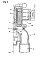
Fig. 4 eine Schnittansicht des Tankabsperrventils entlang der Linie IV-IV derFig. 2 zur Erläuterung des Kondensatablaufs bei stehendem Einbau; -
Fig. 5 eine schematische Schnittansicht des Tankabspenventils zur Erläuterung des Kondensatablaufs bei liegendem Einbau; -
Fig. 6a und 6b unterschiedliche Schnittansichten der beiden Tankdruckregelventile; -
Fig. 7 eine perspektivische Ansicht eines anderen Tankabsperrventils; -
Fig. 8 eine perspektivische Ansicht einer Ventileinheit aus zwei Tankdruckregelventilen; -
Fig. 9 eine Seitenansicht der Ventileinheit ausFig. 8 ; -
Fig. 10 eine Längsschnittansicht der Ventileinheit ausFig. 8 und9 ; -
Fig. 11 eine perspektivische Ansicht einer anderen Ventileinheit aus zwei Tankdruckregelventilen; -
Fig. 12 eine Seitenansicht der Ventileinheit ausFig. 11 ; -
Fig. 13 eine Querschnittsansicht der Ventileinheit ausFig. 11 und 12 . - Die in den
Figuren 1 bis 4 dargestellte Ventileinheit 1 dient zur Entlüftung und Belüftung eines Kraftstofftanks (nicht dargestellt) und ist zum Einbau zwischen dem Kraftstofftank und einem Aktivkohlefilter (nicht dargestellt) bestimmt, der bei einer Entlüftung oder Belüftung des Kraftstofftanks einen Austritt von flüchtigen Kohlenwasserstoffen in die Atmosphäre oder Umgebung verhindert. - Die Ventileinheit 1 besteht im Wesentlichen aus einem Tankabsperrventil 2 und zwei voneinander getrennten Tankdruckregelventilen 3, 4, die an entgegengesetzten Seiten des Tankabsperrventils 2 angeordnet sind.
- Das Tankabsperrventil 2 ist ein Elektromagnetventil, das aus zwei drehbar miteinander verbundenen Teilen besteht, nämlich einem Venfilteil 5 mit einem Ventilsitz 6, einem in Bezug zum Ventilsitz 6 beweglichen Ventilglied 7 und zwei Anschlüssen 8, 9, d.h. einem mit dem Kraftstofftank verbindbaren Tankanschluss 8 und einem mit einem Aktivkohlefilter verbindbaren Filteranschluss 9, sowie einem Ventilbetäfigungsteil 10 mit einer Elektromagnetspule 11 und einem auf das Ventilglied 7 einwirkenden Anker 12. Wenn die Elektromagnetspule 11 erregt wird, hebt der Anker 12 das Ventilglied 7 vom Ventilsitz 6 ab, woraufhin die beiden Anschlüsse 8, 9 miteinander kommunizieren.
- Wie am besten in den
Figuren 1 ,3 ,4 und5 dargestellt, kann die Ventileinheit 1 in verschiedenen Einbaulagen montiert werden, nämlich stehend, wie inFig. 1 ,3 und4 dargestellt, d.h. mit vertikaler Längsmittelachse 13, oder liegend, wie inFig. 5 schematisch ohne die beiden Tankdruckregelventile 3, 4 dargestellt, d.h. mit horizontaler Längsmittelachse 13. Selbstverständlich kann die Ventileinheit 1 auch in einer beliebigen schrägen Einbaulage zwischen stehend und liegend montiert werden. - Um zu verhindern, dass sich in einer dieser Einbaulagen im Inneren des Tankabsperrventils 2 flüssiges Kondensat ansammeln kann, ist das Tankabsperrventil 2 so konstruiert, dass bei stehendem Einbau der Tankanschluss 8 und der Filteranschluss 9 an der Unterseite des Ventilteils 5 angeordnet sind, nach unten über den Ventilteil 5 überstehen und sich beide nach unten zu öffnen, wie in
Fig. 1 ,3 und4 dargestellt. Darüber hinaus ist jeder der beiden Anschlüsse 8, 9 derart mit einem mit dem Tankanschluss 8 bzw. mit dem Filteranschluss 9 kommunizierenden Innenräumen 14 bzw. 15 des Tankabsperrventils 2 verbunden, dass in den Innenräumen 14, 15 kondensierender Kraftstoffdampf vollständig in den Anschluss 8, 9 fließt, der sowohl bei stehendem und bei liegendem Einbau des Ventils 1 von unten her in den Innenraum 14 bzw. 15 mündet, wie am besten inFig. 3 und4 bzw. 5 dargestellt. Um den Ablauf von Kondensat aus den Innenräumen 14, 15 in die Anschlüsse 8 bzw. 9 zu erleichtern, werden beide Innenräume 14, 15 bei stehendem Einbau (Fig. 3 und4 ) nach unten zu von schrägen Flächen 16 und bei liegendem Einbau nach unten zu von schrägen Flächen 17 begrenzt, die zu den Einmündungen der Anschlüsse 8, 9 hin nach unten geneigt sind. Bei geschlossenem Ventil 2 sind die Innenräume 14, 15 durch das Ventilglied 7 voneinander getrennt. - Weiter ist das Tankabspenventil 2 so konstruiert, dass beide Anschlüsse 8, 9 auf einer Seite einer Längsmittelebene 18 (
Fig. 2 ) des Tankabsperrventils 2 angeordnet sind, welche bei stehendem Einbau vertikal ausgerichtet ist, und dass der Ventilteil 5 in Bezug zu dem mit Befestigungsmitteln 19 versehenen Ventilbetätigungsteil 10 um die Längsmittelachse 13 des Tankabsperrventils 2 drehbar und in einer beliebigen Drehlage fixierbar ist, wie am besten inFig. 1 ,3 und4 durch einen Spannring 20 dargestellt, so dass der Ventilteil 5 bei liegendem Einbau ungeachtet der Ausrichtung der Befestigungsmittel 19 immer in eine Stellung gedreht werden kann, in der die beiden Anschlüsse 8, 9 unterhalb von der Längsmittelebene 18 angeordnet sind und sich nach einer Seite zu öffnen, wie inFig. 5 dargestellt. Darüber hinaus ist der Tankanschluss 8 derart mit dem Innenraum 14 und der Filteranschluss 9 derart mit dem Innenraum 15 verbunden, dass in den Innenräumen 14, 15 kondensierender Kraftstoffdampf vollständig in den von unten her in den Innenraum 14, 15 mündenden Anschluss 8 bzw. 9 fließt, wie inFig. 5 dargestellt. Damit können in jeder Einbaulage zwischen stehend und liegend Totkraftstoffbereiche vermieden werden. - Die beiden als Ventileinheit mit dem Tankabsperrventil 2 ausgebildeten Tankdruckregelventile 3, 4 sind Bypassventile, von denen eines ein Unterdruckventil 3 und das andere ein Überdruckventil 4 ist. Das Unterdruckventil 3 öffnet sich ebenfalls selbsttätig, wenn sich im Kraftstofftank ein definierter Unterdruck einstellt. Das Überdruckventil 4 öffnet sich selbsttätig, wenn sich im Kraftstofftank ein definierter Überdruck einstellt.
- Wie am besten in
Fig. 6a und 6b dargestellt, weisen die beiden Tankdruckregelventile 3, 4 jeweils zwei durch eine Membran 21 getrennte Kammem 22, 23; 24, 25 auf, von denen nach der Montage der Ventileinheit 1 jeweils eine 22; 24 mit dem Kraftstofftank und eine 23; 25 mit dem Aktivkohlefilter kommuniziert. Bei dem Unterdruckventil 3 inFig. 6a ist die mit dem Kraftstofftank kommunizierende Unterdruckkammer 22 vom Tankabsperrventil 2 abgewandt, während die andere, mit dem Aktivkohlefilter kommunizierende Kammer 23 dem Tankabsperrventil 2 zugewandt ist. Bei dem Überdruckventil 4 inFig. 6b ist hingegen die mit dem Kraftstofftank kommunizierende Überdruckkammer 24 dem Tankabsperrventil 2 zugewandt, während die andere, mit dem Aktivkohlefilter kommunizierende Kammer 25 vom Tankabsperrventil 2 abgewandt ist. Wie am besten inFig. 6b dargestellt, ist die Membran 21 jedes Ventils 3, 4 mit einer Öffnung 26 versehen und liegt bei geschlossenem Ventil 3, 4 um die Öffnung 26 herum auf einem zylindrischen Rohrstutzen 27 auf, durch den bei dem Unterdruckventil 3 inFig. 6a die Unterdruckkammer 22 mit dem Kraftstofftank und bei dem Überdruckventil 4 inFig. 6b die andere Kammer 25 mit dem Aktivkohlefilter kommuniziert. Die Membran 21 wird von einer Feder 28 gegen das freie obere Ende des Rohrstutzens 27 angepresst und sorgt dafür, dass die beiden Kammem 22, 23; 24, 25 bei geschlossenem Ventil 3, 4, d.h. normalerweise, nicht miteinander kommunizieren. Im Fall eines stärkeren Unterdrucks im Kraftstofftank wird die Membran 21 des Unterdruckventils 3 infolge des Unterdrucks in der durch den Rohrstutzen 27 mit dem Kraftstofftank kommunizierenden Unterdruckkammer 22 entgegen der Kraft der Feder 28 vom Rohrstutzen 27 abgehoben, wodurch die beiden Kammem 22, 23 unter Öffnen des Ventils 3 miteinander verbunden werden. Im Falle eines stärkeren Überdrucks im Kraftstofftank wird die Membran 21 des Überdruckventils 4 durch den Druck in der Überdruckkammer 24 entgegen der Kraft der Feder 28 vom Rohrstutzen 27 abgehoben, wodurch die beiden Kammem 24, 25 ebenfalls unter Öffnen des Ventils 4 miteinander verbunden werden. - Die Überdruckkammer 24 des Überdruckventils 4 und die Unterdruckkammer 22 des Unterdruckventils 3 kommunizieren durch den Innenraum 14 des Tankabsperrventils 2 hindurch mit dem Tankanschluss 8, während die andere Kammer 25 des Überdruckventils 4 und die andere Kammer 22 des Unterdruckventils 3 durch den Innenraum 15 des Tankabsperrventils 2 hindurch mit dem Filteranschluss 9 kommunizieren.
- Die Ventileinheit kann nicht nur in stehender Einbaulage, wie in
Fig. 1 dargestellt, und in liegender Einbaulage, wie inFig. 5 dargestellt, sondern auch in jeder beliebigen dazwischen liegenden Ausrichtung montiert werden, wobei in sämtlichen Fällen die beiden Anschlüsse 8, 9 schräg nach unten weisen und an der tiefsten Stelle in die jeweilige Kammer münden, so dass ein guter Kondensatablauf sichergestellt ist. - Das in
Fig. 7 dargestellte Tankabsperrventil 2 weist dieselbe Konstruktion wie das Tankabspenventil 2 in denFiguren 1 ,2 ,3 und5 auf, bildet jedoch eine separate Ventileinheit 41, die getrennt von einer aus den beiden Tankdruckregelventilen 3 und 4 bestehenden, in denFiguren 8 bis 13 dargestellten Ventileinheit 29 bzw. 30 montiert werden kann, zum Beispiel die Ventileinheit 41 außerhalb des Kraftstofftanks und eine der beiden Ventileinheiten 29, 30 innerhalb des Kraftstofftanks. - Bei der in den
Figuren 8 bis 10 dargestellten Ventileinheit 29 weisen die beiden Tankdruckregelventile, d.h. das Unterdruckventil 3 und das Überdruckventil 4, dieselbe Ausrichtung auf und sind nebeneinander entlang eines Anschlussteils 31 angeordnet, während bei der Ventileinheit 30 in denFiguren 11 bis 13 die beiden Tankdruckregelventile 3, 4 entgegengesetzte Ausrichtungen aufweisen und an einem Ende eines Anschlussteils 32 angeordnet sind. - Bei beiden Ventileinheiten 29, 30 sind die mit dem Kraftstofftank kommunizierende Unterdruckkammer 22 des Unterdruckventils 3 und die ebenfalls mit dem Kraftstofftank kommunizierende Überdruckkammer 24 des Überdruckventils 4 mit einem gemeinsamen Tankanschluss 33 der Ventileinheit 29, 30 verbunden, während die mit dem Aktivkohlefilter kommunizierende andere Kammer 23 des Unterdruckventils 3 und die ebenfalls mit dem Aktivkohlefilter kommunizierende andere Kammer 25 des Überdruckventils 4 mit einem gemeinsamen Filteranschluss 34 der Ventileinheit 29, 30 verbunden sind.
- Wie am besten in
Fig. 10 dargestellt, mündet bei der Ventileinheit 29 in denFiguren 8 bis 10 der Rohrstutzen 27 des Unterdruckventils 3 von unten her in die Unterdruckkammer 22, während sein unteres Ende durch eine nach der Montage der Ventileinheit 29 horizontal ausgerichtete Röhre 35 im Anschlussteil 31 mit dem Tankanschluss 33 kommuniziert, so dass kondensierender Kraftstoff aus der Unterdruckkammer 22 durch den Rohrstutzen 21 zum Tankanschluss 33 abfließen kann. Die Überdruckkammer 24 des Überdruckventils 4 wird an ihrer Unterseite von einem schrägen Boden 36 begrenzt und kommuniziert an ihrer tiefsten Stelle durch einen Durchlass 37 mit der zum Tankanschluss 33 führenden Röhre 35, so dass das Kondensat aus der Überdruckkammer 24 ebenfalls vollständig zum Tankanschluss 33 abfließen kann. - Umgekehrt mündet bei der Ventileinheit 29 der Rohrstutzen 27 des Überdruckventils 4 von unten her in die andere Kammer 25, während sein unteres Ende durch eine nach der Montage der Ventileinheit 29 parallel zu der Röhre 35 ausgerichtete Röhre (nicht sichtbar) im Anschlussteil 31 mit einem Filteranschluss 34 kommuniziert, so dass kondensierender Kraftstoff aus der Kammer 25 durch den Rohrstutzen 21 zum Filteranschluss 34 abfließen kann. Die andere Kammer 23 des Unterdruckventils 3 wird an ihrer Unterseite ebenfalls von einem schrägen Boden (nicht sichtbar) begrenzt und kommuniziert an ihrer tiefsten Stelle durch einen Durchlass (nicht sichtbar) mit der zum Filteranschluss 34 führenden Röhre, so dass das Kondensat aus der Kammer 23 ebenfalls vollständig zum Filteranschluss 34 abfließen kann.
- Wie am besten in
Fig. 13 dargestellt, kommuniziert bei der Ventileinheit 30 in denFiguren 11 bis 13 die Kammer 25 des Überdruckventils 4 nicht nur durch den Rohrstutzen 27 sondern zusätzlich durch einen weiteren Durchlass 39 an der tiefsten Stelle der Kammer 25 mit einer zum Filteranschluss 34 führenden vertikalen Röhre 38 im Anschlussteil 32, so dass Kondensat aus der Kammer 25 durch den Durchlass 39 und die Röhre 38 zum Filteranschluss 34 abfließen kann. Die Überdruckkammer 24 des Überdruckventils 4 ist ähnlich wie die Überdruckkammer 24 beim Überdruckventil 4 der Ventileinheit 29 durch einen einzigen, an der tiefsten Stelle der Kammer 24 angeordneten Durchlass 40 mit der vertikalen Röhre 38 im Anschlussteil 32 verbunden, wie inFig. 12 dargestellt. - Das Unterdruckventil 3 (in
Fig. 13 nur teilweise dargestellt) weist einen entsprechenden Aufbau auf, wobei jedoch die andere Kammer 23 durch einen Durchlass 40 an ihrer tiefsten Stelle mit der zum Filteranschluss 34 führenden vertikalen Röhre 38 kommuniziert, während die Unterdruckkammer (nicht sichtbar) durch den Rohrstutzen 27 und einen weiteren Durchlass 39 an der tiefsten Stelle der Unterdruckkammer mit einer zur Röhre 38 parallelen, zum Tankanschluss 33 führenden Röhre im Anschlussteil 32 kommuniziert, wie am besten inFig. 11 und 12 dargestellt. -
- 1
- Ventileinheit
- 2
- Tankabsperrventil
- 3
- Unterdruckventil
- 4
- Überdruckventil
- 5
- Ventilteil Tankabsperrventil
- 6
- Ventilsitz
- 7
- Ventilglied
- 8
- Tankanschluss Tankabsperrventil
- 9
- Filteranschluss Tankabsperrventil
- 10
- Ventilbetätigungsteil Tankabsperrventil
- 11
- Elektromagnetspule
- 12
- Anker
- 13
- Längsmittelachse
- 14
- Innenraum
- 15
- Innenraum
- 16
- Schrägfläche
- 17
- Schrägfläche
- 18
- Längsmittelebene
- 19
- Befestigungsmittel
- 20
- Spannring
- 21
- Membran
- 22
- Unterdruckkammer
- 23
- andere Kammer
- 24
- Überdruckkammer
- 25
- andere Kammer
- 26
- Öffnung
- 27
- Rohrstutzen
- 28
- Feder
- 29
- Ventileinheit
- 30
- Ventileinheit
- 31
- Anschlussteil
- 32
- Anschlussteil
- 33
- Tankanschluss
- 34
- Filteranschluss
- 35
- Röhre
- 36
- schräger Boden
- 37
- Durchlass
- 38
- Röhre
- 39
- weiterer Durchlass
- 40
- Durchlass
- 41
- Ventileinheit
Claims (12)
- Einrichtung zur Entlüftung und Belüftung eines Kraftstofftanks, mit einem Tankabsperrventil und zwei Tankdruckregelventilen, von denen eines im Falle eines Unterdrucks im Kraftstofftank und eines im Falle eines Überdrucks im Kraftstofftank öffnet, wobei eine aus einem oder mehreren der Ventile bestehende Ventileinheit stehend und liegend montierbar ist und einen mit dem Kraftstofftank kommunizierenden Tankanschluss und einen mit einem Aktivkohlefilter kommunizierenden Filteranschluss aufweist, dadurch gekennzeichnet, dass die beiden Anschlüsse (8, 9; 33, 34) allgemein parallel ausgerichtet sind, wobei sie bei stehender Einbaulage der Ventileinheit (1; 41; 30) nach unten und bei liegender Einbaulage der Ventileinheit (1; 29) in seitliche Richtung(en) weisen und an oder nahe der Unterseite der Ventileinheit (1; 41; 29) angeordnet sind.
- Einrichtung nach Anspruch 1, dadurch gekennzeichnet, dass die Ventileinheit (1; 41) zwei in Bezug zueinander drehbare Teile (5, 10) umfasst, von denen eines (10) mit Befestigungsmitteln (19) zum Befestigen der Ventileinheit (2) an einer Halterung und eines (5) mit den beiden Anschlüssen (8, 9) versehen ist.
- Einrichtung nach Anspruch 2, gekennzeichnet durch Mittel (20) zum Fixieren der beiden Teile (5, 10) in Bezug zueinander in einer beliebigen Drehlage.
- Einrichtung nach einem der Ansprüche 1 bis 3, dadurch gekennzeichnet, dass die beiden Anschlüsse (8, 9) bei liegender Einbaulage der Ventileinheit (1; 41) in dieselbe Richtung weisen.
- Einrichtung nach einem der Ansprüche 1 bis 3, dadurch gekennzeichnet, dass die beiden Anschlüsse (33, 34) bei liegender Einbaulage der Ventileinheit (29) in entgegengesetzte Richtungen weisen.
- Einrichtung nach einem der vorangehenden Ansprüche, dadurch gekennzeichnet, dass jedes der beiden Tankdruckregelventile (3; 4) zwei durch eine Membran (21) getrennte Kammem (22, 23; 24, 25) aufweist, und dass die Kammem (22, 23; 24, 25) jeweils paarweise mit einem der beiden Anschlüsse (8, 9; 33, 34) kommunizieren.
- Einrichtung nach Anspruch 6, dadurch gekennzeichnet, dass die Kammem (22, 23; 24, 25) jeweils an ihrer tiefsten Stelle durch eine Öffnung (26) oder einen Durchlass (37, 39, 40) mit einem der beiden Anschlüsse (8, 9; 33, 34) kommunizieren.
- Einrichtung nach einem der vorangehenden Ansprüche, dadurch gekennzeichnet, dass jeder der beiden Anschlüsse (8, 9) in einen Innenraum (14, 15) der Ventileinheit (1; 41) mündet, und dass die Einmündungen der Anschlüsse (8, 9) in die Innenräume (14 bzw. 15) sowohl bei stehender und bei liegender Einbaulage an der tiefsten Stelle des jeweiligen Innenraums (14 bzw. 15) angeordnet sind.
- Einrichtung nach Anspruch 8, dadurch gekennzeichnet, dass die Einmündungen mindestens zum Teil von schrägen, zu den Einmündungen hin nach unten geneigten Flächen (16, 17) umgeben sind.
- Einrichtung nach einem der Ansprüche 1 bis 9, dadurch gekennzeichnet, dass die Ventileinheit (1) die beiden Tankdruckregelventile (3, 4) und das mit den beiden Anschlüssen (8, 9) versehene Tankabsperrventil (2) umfasst, und dass die beiden Tankdruckregelventile (3, 4) durch das Tankabsperrventil (2) hindurch mit den beiden Anschlüssen (8, 9) kommunizieren.
- Einrichtung nach einem der Ansprüche 1 bis 9, dadurch gekennzeichnet, dass die Ventileinheit (41) nur das Tankabsperrventil (2) umfasst.
- Einrichtung nach einem der Ansprüche 1 bis 9, dadurch gekennzeichnet, dass die Ventileinheit (29, 30) nur die beiden Tankdruckregelventile (3, 4) umfasst.
Applications Claiming Priority (1)
| Application Number | Priority Date | Filing Date | Title |
|---|---|---|---|
| DE102010055312.3A DE102010055312B4 (de) | 2010-12-21 | 2010-12-21 | Einrichtung zur Entlüftung und Belüftung eines Kraftstofftanks |
Publications (2)
| Publication Number | Publication Date |
|---|---|
| EP2468559A2 true EP2468559A2 (de) | 2012-06-27 |
| EP2468559A3 EP2468559A3 (de) | 2018-04-18 |
Family
ID=45421772
Family Applications (1)
| Application Number | Title | Priority Date | Filing Date |
|---|---|---|---|
| EP11009835.7A Withdrawn EP2468559A3 (de) | 2010-12-21 | 2011-12-14 | Einrichtung zur Entlüftung und Belüftung eines Kraftstofftanks |
Country Status (4)
| Country | Link |
|---|---|
| US (1) | US8967193B2 (de) |
| EP (1) | EP2468559A3 (de) |
| CN (1) | CN102529697B (de) |
| DE (1) | DE102010055312B4 (de) |
Families Citing this family (7)
| Publication number | Priority date | Publication date | Assignee | Title |
|---|---|---|---|---|
| DE102010055316B4 (de) * | 2010-12-21 | 2016-09-08 | Audi Ag | Einrichtung zur Entlüftung und Belüftung eines Kraftstofftanks |
| DE102011106006B4 (de) | 2011-06-30 | 2019-05-16 | Audi Ag | Verfahren zum Betreiben eines Kraftstoffsystems sowie Kraftstoffsystem |
| DE102011106008B4 (de) | 2011-06-30 | 2018-10-31 | Audi Ag | Verfahren zum Betreiben eines Kraftstoffsystems sowie Kraftstoffsystem |
| DE102015012656B4 (de) | 2014-10-22 | 2025-07-17 | Audi Ag | Verfahren zum Betreiben einer Kraftstoffanlage für ein Kraftfahrzeug sowie entsprechende Kraftstoffanlage |
| DE102015005754A1 (de) | 2015-05-05 | 2016-11-10 | Audi Ag | Magnetventileinrichtung für ein Kraftfahrzeug |
| DE102015010354B4 (de) | 2015-08-06 | 2017-03-16 | Audi Ag | Betriebsmitteltankanordnung für ein Kraftfahrzeug |
| DE102017125283A1 (de) * | 2017-10-27 | 2019-05-02 | Alfmeier Präzision SE | Ventilsystem für einen Kraftstofftank |
Family Cites Families (21)
| Publication number | Priority date | Publication date | Assignee | Title |
|---|---|---|---|---|
| US4893643A (en) * | 1989-02-27 | 1990-01-16 | General Motors Corporation | Tank vapor vent valve assembly with improved overfill protection |
| US5014742A (en) * | 1990-04-05 | 1991-05-14 | General Motors Corporation | Vacuum actuated tank vapor vent valve |
| DE4241274C2 (de) | 1992-12-08 | 1999-02-11 | Freudenberg Carl Fa | Vorrichtung zum Einspeisen der im Freiraum eines Kraftstoffbehälters befindlichen Dämpfe in das Ansaugrohr einer Verbrennungskraftmaschine |
| US6142167A (en) * | 1999-03-01 | 2000-11-07 | Technalink, Inc. | Tanker roll shut-off vent valve assembly |
| DE19913937A1 (de) * | 1999-03-26 | 2000-10-05 | Alfmeier Praezision Ag | Einrichtung zum Ent- und Belüften eines Kraftstofftanks |
| JP3678088B2 (ja) * | 1999-11-26 | 2005-08-03 | 日産自動車株式会社 | 蒸発燃料処理装置 |
| US6769416B2 (en) * | 2001-05-11 | 2004-08-03 | Mitsubishi Denki Kabushiki Kaisha | Evaporated fuel processing module |
| US6668876B2 (en) * | 2001-06-14 | 2003-12-30 | Siemens Vdo Automotive, Incorporated | Method for fuel vapor pressure management |
| JP4123431B2 (ja) * | 2003-01-24 | 2008-07-23 | 京三電機株式会社 | 蒸発燃料処理装置 |
| JP2005155712A (ja) * | 2003-11-21 | 2005-06-16 | Mitsubishi Electric Corp | 電磁弁 |
| US7325577B2 (en) * | 2004-07-19 | 2008-02-05 | Stant Manufacturing Inc. | Tank venting system |
| JP2006258283A (ja) * | 2005-02-18 | 2006-09-28 | Denso Corp | 流体制御弁、および電磁弁 |
| JP3808491B2 (ja) * | 2005-08-02 | 2006-08-09 | 三菱電機株式会社 | ソレノイドバルブ |
| TW200840739A (en) * | 2007-04-10 | 2008-10-16 | Sentec E & E Co Ltd | Fuel tank with control of volatilization and spillage of fuel |
| DE102007025048B4 (de) * | 2007-05-29 | 2012-08-30 | Eagle Actuator Components Gmbh & Co. Kg | Ventil zur Begrenzung des Tankdrucks eines Kraftfahrzeugs |
| US8171952B2 (en) * | 2008-02-01 | 2012-05-08 | Eaton Corporation | Multi-function control valve for fuel vapor system |
| JP5020380B2 (ja) | 2008-09-01 | 2012-09-05 | 三菱電機株式会社 | キャニスタ・ベント・ソレノイドバルブの保護カバー |
| JP2011161974A (ja) * | 2010-02-05 | 2011-08-25 | Toyota Motor Corp | 燃料タンク、並びに同燃料タンクを具備する蒸発燃料処理装置 |
| DE102010055318B4 (de) * | 2010-12-21 | 2025-06-12 | Audi Ag | Verfahren und Einrichtung zur Steuerung des Drucks im Inneren eines Kraftstofftanks |
| DE102010055311B4 (de) * | 2010-12-21 | 2016-07-14 | Audi Ag | Einrichtung zur Entlüftung und Belüftung eines Kraftstofftanks |
| DE102010055319A1 (de) * | 2010-12-21 | 2012-06-21 | Audi Ag | Einrichtung zum Be- und Entlüften eines Kraftstofftanks |
-
2010
- 2010-12-21 DE DE102010055312.3A patent/DE102010055312B4/de not_active Expired - Fee Related
-
2011
- 2011-12-14 EP EP11009835.7A patent/EP2468559A3/de not_active Withdrawn
- 2011-12-16 US US13/328,354 patent/US8967193B2/en not_active Expired - Fee Related
- 2011-12-21 CN CN201110432486.2A patent/CN102529697B/zh not_active Expired - Fee Related
Also Published As
| Publication number | Publication date |
|---|---|
| US8967193B2 (en) | 2015-03-03 |
| CN102529697A (zh) | 2012-07-04 |
| US20120160219A1 (en) | 2012-06-28 |
| DE102010055312A1 (de) | 2012-06-21 |
| DE102010055312B4 (de) | 2016-07-07 |
| EP2468559A3 (de) | 2018-04-18 |
| CN102529697B (zh) | 2016-03-30 |
Similar Documents
| Publication | Publication Date | Title |
|---|---|---|
| DE102010055312B4 (de) | Einrichtung zur Entlüftung und Belüftung eines Kraftstofftanks | |
| DE102010055311B4 (de) | Einrichtung zur Entlüftung und Belüftung eines Kraftstofftanks | |
| DE102010055318B4 (de) | Verfahren und Einrichtung zur Steuerung des Drucks im Inneren eines Kraftstofftanks | |
| DE102010055316B4 (de) | Einrichtung zur Entlüftung und Belüftung eines Kraftstofftanks | |
| DE102010019831B4 (de) | Tankentlüftungseinrichtung für einen Kraftstofftank eines Kraftfahrzeugs | |
| DE102010044336A1 (de) | Entlüftungsanordnung für einen Kraftstofftank | |
| EP0296618B1 (de) | Selbstschliessender Kraftstoffbehälterverschluss | |
| EP0464420A1 (de) | Tankfüllstutzen für einen Treibstofftank | |
| DE102011114120A1 (de) | Entlüftungsanordnung für einen Kraftstofftank | |
| DE102013013212A1 (de) | Universelles Abschaltventil | |
| DE102005036932B3 (de) | Entlüftungsventil für den Kraftstoffbehälter von Kraftfahrzeugen | |
| EP0155346A2 (de) | Reifendruckregelanlage | |
| EP0568005B1 (de) | Tankentlüftungsventil | |
| DE60132542T2 (de) | System zur Rückgewinnung von Kraftstoffdämpfen | |
| DE3819689A1 (de) | Absperrventil | |
| DE102016123444B4 (de) | Behälterventilvorrichtung für ein Fahrzeug | |
| DE3531159C1 (de) | Ventilvorrichtung zum Be- und Entlueften von Kraftstoffbehaeltern fuer Kraftfahrzeuge | |
| DE102007012482B4 (de) | Ölabscheider, Abscheideverfahren und deren Verwendung | |
| DE1280617B (de) | Vergaser fuer Brennkraftmaschinen | |
| DE2406843B2 (de) | Druckausgleichsanordnung für einen Fahrzeug-Kraftstoffbehälter | |
| DE2422165A1 (de) | Vorrichtung zur begrenzung der gasstroemung aus einem und in einen behaelter | |
| WO2011113457A1 (de) | Kraftstofffiltereinrichtung | |
| DE202005020971U1 (de) | Entlüftungsventil für den Kraftstoffbehälter von Kraftfahrzeugen | |
| EP3649693B1 (de) | Fahrzeug mit einem brennstoffzellensystem und verfahren zur behandlung eines aus dem brennstoffzellensystem austretenden fluids | |
| DE4405982A1 (de) | Kraftstoffanlage für eine Brennkraftmaschine mit einem Adsorber für Kraftstoffdämpfe |
Legal Events
| Date | Code | Title | Description |
|---|---|---|---|
| AK | Designated contracting states |
Kind code of ref document: A2 Designated state(s): AL AT BE BG CH CY CZ DE DK EE ES FI FR GB GR HR HU IE IS IT LI LT LU LV MC MK MT NL NO PL PT RO RS SE SI SK SM TR |
|
| AX | Request for extension of the european patent |
Extension state: BA ME |
|
| PUAI | Public reference made under article 153(3) epc to a published international application that has entered the european phase |
Free format text: ORIGINAL CODE: 0009012 |
|
| PUAL | Search report despatched |
Free format text: ORIGINAL CODE: 0009013 |
|
| AK | Designated contracting states |
Kind code of ref document: A3 Designated state(s): AL AT BE BG CH CY CZ DE DK EE ES FI FR GB GR HR HU IE IS IT LI LT LU LV MC MK MT NL NO PL PT RO RS SE SI SK SM TR |
|
| AX | Request for extension of the european patent |
Extension state: BA ME |
|
| RIC1 | Information provided on ipc code assigned before grant |
Ipc: B60K 15/035 20060101AFI20180313BHEP |
|
| STAA | Information on the status of an ep patent application or granted ep patent |
Free format text: STATUS: THE APPLICATION HAS BEEN WITHDRAWN |
|
| 18W | Application withdrawn |
Effective date: 20180412 |