EP2467656B1 - Kältegerät mit einem abtauwasserkanal und einem siphon - Google Patents
Kältegerät mit einem abtauwasserkanal und einem siphon Download PDFInfo
- Publication number
- EP2467656B1 EP2467656B1 EP10743123.1A EP10743123A EP2467656B1 EP 2467656 B1 EP2467656 B1 EP 2467656B1 EP 10743123 A EP10743123 A EP 10743123A EP 2467656 B1 EP2467656 B1 EP 2467656B1
- Authority
- EP
- European Patent Office
- Prior art keywords
- siphon
- refrigerator
- defrost water
- evaporation tray
- evaporator pan
- Prior art date
- Legal status (The legal status is an assumption and is not a legal conclusion. Google has not performed a legal analysis and makes no representation as to the accuracy of the status listed.)
- Active
Links
- XLYOFNOQVPJJNP-UHFFFAOYSA-N water Substances O XLYOFNOQVPJJNP-UHFFFAOYSA-N 0.000 claims description 50
- 239000007789 gas Substances 0.000 claims description 6
- 239000004033 plastic Substances 0.000 claims description 5
- 239000002918 waste heat Substances 0.000 claims description 3
- 229920001169 thermoplastic Polymers 0.000 claims description 2
- 239000004416 thermosoftening plastic Substances 0.000 claims description 2
- 230000007704 transition Effects 0.000 claims description 2
- 239000004020 conductor Substances 0.000 claims 1
- 239000002826 coolant Substances 0.000 claims 1
- 229920001971 elastomer Polymers 0.000 claims 1
- 239000000806 elastomer Substances 0.000 claims 1
- 238000001704 evaporation Methods 0.000 description 45
- 230000008020 evaporation Effects 0.000 description 45
- 238000005057 refrigeration Methods 0.000 description 8
- 239000003570 air Substances 0.000 description 6
- 239000003507 refrigerant Substances 0.000 description 5
- 239000012080 ambient air Substances 0.000 description 4
- 238000010257 thawing Methods 0.000 description 3
- 230000015572 biosynthetic process Effects 0.000 description 2
- 238000009434 installation Methods 0.000 description 2
- 238000009413 insulation Methods 0.000 description 2
- 241000190070 Sarracenia purpurea Species 0.000 description 1
- 238000009825 accumulation Methods 0.000 description 1
- 230000006835 compression Effects 0.000 description 1
- 238000007906 compression Methods 0.000 description 1
- 238000001816 cooling Methods 0.000 description 1
- 230000009849 deactivation Effects 0.000 description 1
- 230000004941 influx Effects 0.000 description 1
- 238000002347 injection Methods 0.000 description 1
- 239000007924 injection Substances 0.000 description 1
- 239000000463 material Substances 0.000 description 1
- 239000000243 solution Substances 0.000 description 1
Images


Classifications
-
- F—MECHANICAL ENGINEERING; LIGHTING; HEATING; WEAPONS; BLASTING
- F25—REFRIGERATION OR COOLING; COMBINED HEATING AND REFRIGERATION SYSTEMS; HEAT PUMP SYSTEMS; MANUFACTURE OR STORAGE OF ICE; LIQUEFACTION SOLIDIFICATION OF GASES
- F25D—REFRIGERATORS; COLD ROOMS; ICE-BOXES; COOLING OR FREEZING APPARATUS NOT OTHERWISE PROVIDED FOR
- F25D21/00—Defrosting; Preventing frosting; Removing condensed or defrost water
- F25D21/14—Collecting or removing condensed and defrost water; Drip trays
-
- F—MECHANICAL ENGINEERING; LIGHTING; HEATING; WEAPONS; BLASTING
- F25—REFRIGERATION OR COOLING; COMBINED HEATING AND REFRIGERATION SYSTEMS; HEAT PUMP SYSTEMS; MANUFACTURE OR STORAGE OF ICE; LIQUEFACTION SOLIDIFICATION OF GASES
- F25D—REFRIGERATORS; COLD ROOMS; ICE-BOXES; COOLING OR FREEZING APPARATUS NOT OTHERWISE PROVIDED FOR
- F25D2321/00—Details or arrangements for defrosting; Preventing frosting; Removing condensed or defrost water, not provided for in other groups of this subclass
- F25D2321/14—Collecting condense or defrost water; Removing condense or defrost water
- F25D2321/141—Removal by evaporation
- F25D2321/1411—Removal by evaporation using compressor heat
-
- F—MECHANICAL ENGINEERING; LIGHTING; HEATING; WEAPONS; BLASTING
- F25—REFRIGERATION OR COOLING; COMBINED HEATING AND REFRIGERATION SYSTEMS; HEAT PUMP SYSTEMS; MANUFACTURE OR STORAGE OF ICE; LIQUEFACTION SOLIDIFICATION OF GASES
- F25D—REFRIGERATORS; COLD ROOMS; ICE-BOXES; COOLING OR FREEZING APPARATUS NOT OTHERWISE PROVIDED FOR
- F25D2321/00—Details or arrangements for defrosting; Preventing frosting; Removing condensed or defrost water, not provided for in other groups of this subclass
- F25D2321/14—Collecting condense or defrost water; Removing condense or defrost water
- F25D2321/144—Collecting condense or defrost water; Removing condense or defrost water characterised by the construction of drip water collection pans
- F25D2321/1442—Collecting condense or defrost water; Removing condense or defrost water characterised by the construction of drip water collection pans outside a refrigerator
-
- F—MECHANICAL ENGINEERING; LIGHTING; HEATING; WEAPONS; BLASTING
- F25—REFRIGERATION OR COOLING; COMBINED HEATING AND REFRIGERATION SYSTEMS; HEAT PUMP SYSTEMS; MANUFACTURE OR STORAGE OF ICE; LIQUEFACTION SOLIDIFICATION OF GASES
- F25D—REFRIGERATORS; COLD ROOMS; ICE-BOXES; COOLING OR FREEZING APPARATUS NOT OTHERWISE PROVIDED FOR
- F25D2321/00—Details or arrangements for defrosting; Preventing frosting; Removing condensed or defrost water, not provided for in other groups of this subclass
- F25D2321/14—Collecting condense or defrost water; Removing condense or defrost water
- F25D2321/145—Collecting condense or defrost water; Removing condense or defrost water characterised by multiple collecting pans
-
- F—MECHANICAL ENGINEERING; LIGHTING; HEATING; WEAPONS; BLASTING
- F25—REFRIGERATION OR COOLING; COMBINED HEATING AND REFRIGERATION SYSTEMS; HEAT PUMP SYSTEMS; MANUFACTURE OR STORAGE OF ICE; LIQUEFACTION SOLIDIFICATION OF GASES
- F25D—REFRIGERATORS; COLD ROOMS; ICE-BOXES; COOLING OR FREEZING APPARATUS NOT OTHERWISE PROVIDED FOR
- F25D2321/00—Details or arrangements for defrosting; Preventing frosting; Removing condensed or defrost water, not provided for in other groups of this subclass
- F25D2321/14—Collecting condense or defrost water; Removing condense or defrost water
- F25D2321/146—Collecting condense or defrost water; Removing condense or defrost water characterised by the pipes or pipe connections
-
- F—MECHANICAL ENGINEERING; LIGHTING; HEATING; WEAPONS; BLASTING
- F25—REFRIGERATION OR COOLING; COMBINED HEATING AND REFRIGERATION SYSTEMS; HEAT PUMP SYSTEMS; MANUFACTURE OR STORAGE OF ICE; LIQUEFACTION SOLIDIFICATION OF GASES
- F25D—REFRIGERATORS; COLD ROOMS; ICE-BOXES; COOLING OR FREEZING APPARATUS NOT OTHERWISE PROVIDED FOR
- F25D2500/00—Problems to be solved
- F25D2500/02—Geometry problems
Definitions
- the present invention relates to a refrigeration appliance, in particular domestic refrigeration appliance, with a coolable interior and a Abtauigankanal through which defrost water from the interior of the refrigerator in a located outside of the interior evaporation tray can be discharged, wherein at the transition between the Abtauwasserkanal and the evaporation tray a siphon is arranged.
- the evaporator In a cooling device of the type mentioned, the evaporator is often arranged in an evaporator space separate from the refrigerated goods within the coolable interior (Nofrost device). By means of a circulating air fan, the air cooled by the evaporator is transported to the refrigerated goods. As with all refrigeration appliances, moisture from the ambient air condenses on the evaporator where it forms ice. The evaporator is therefore regularly defrosted, the defrost water is discharged from the interior of the refrigerator via a Abtauwasserkanal. The defrost water flows into a particular located on the back of the refrigerator evaporation tray and evaporates.
- the evaporation tray is in the refrigerator according to US 3 137 146 arranged above the compressor of the refrigerator, so as to reduce the waste heat of the compressor for evaporation to use. There is a risk that the water in the siphon also heats up and evaporates so quickly that the siphon is deactivated before the next time the refrigeration unit or the evaporator is defrosted.
- the fan can suck in ambient air when the siphon is empty. This absorbed moisture can accumulate along the Abtauwasserkanals, but also on fan blades or on the Abtauwasserablauf facing part of the evaporator and its surroundings and lead to ice formation at these points. Since the defrost heaters are not optimally designed for this type of moisture accumulation, this ice formation can permanently disrupt the function of the device or even override the device if defrosting is no longer possible.
- the invention therefore has the task of finding a solution that does not have the disadvantages described above.
- the risk of deactivation of the siphon by evaporation should be reduced without complicating the installation of the siphon.
- the invention solves this problem by a refrigeration device according to claim 1. Since the bottom of the siphon is formed by an elevated region of the defrost water tray (8) and arranged above the water level in the evaporation tray in the maximum filled state, in particular ensures that the water in the siphon is not in heat-conducting contact with the water in the evaporation tray because it is separated from it by an air-filled space.
- a tube opens with its outlet end down into a cup-like container. When water flows into the siphon through the pipe, it fills the cup and closes the outlet end of the pipe.
- the bottom of the siphon is the lowest point of the cup into which the defrost water channel coming from above opens.
- the training as a siphon makes it possible to mount the Abtauwasserkanal separated from the Siphontasse.
- the siphon cup does not need to be mounted as a stand-alone component.
- the section of the Abtauwasserkanals between siphon and evaporation tray is also preferably made of poor thermal conductivity material, in particular thermoplastic or elastomeric plastic.
- the wall thickness of Abtauwasserkanals between siphon and evaporation tray is optimized in terms of poor heat conduction.
- the water level in the evaporation tray in its maximum filled state is the highest defrost water level that can be present in the evaporation tray. This may be the water level just before overflowing the evaporation tray. However, it may also be the water level, which is present directly after a defrost cycle of the refrigerator, so if there is so much defrost water in the evaporation tray, as is defrosted at a maximum from the evaporator chamber or the interior of the refrigerator.
- the bottom of the siphon is the lowest point of the siphon, which can be filled with defrost water.
- the floor does not have to be level, it can also be a round or bulbous floor. In this case, the lowest point of the bottom of the siphon should be above the water level in the evaporation tray.
- the defrosting water located in the evaporation tray can be heated by waste heat from the refrigeration appliance.
- this can be done by arranging the evaporation tray in the vicinity of the compressor of the refrigerator, in particular above the compressor.
- the hot gas pipe heats the water in the evaporation tray and thereby evaporates it.
- the refrigerant coming from the compressor is pre-cooled before it flows through the condenser coils.
- the bottom of the siphon is formed by a raised area of defrosting water.
- the cup of the siphon may be formed integrally with the evaporation tray.
- the overflowing from the siphon water is safely collected in the evaporation tray.
- the bottom of the siphon is arranged, for example, 0.5 cm - 10 cm above the water level of the evaporation tray in the maximum filled state. That way avoided that a heat exchange between the defrost water in the evaporation tray and the water takes place in the siphon, since there is an air-filled gap between them.
- the siphon is provided with a cover. This further reduces the evaporation of water from the siphon.
- the refrigerator is in particular a household refrigeration appliance, for example a refrigerator, a freezer, a wine cabinet or a fridge-freezer.
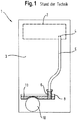
- Fig. 1 schematically shows the back of a household refrigerator 1.
- the dashed line 2 of the evaporator chamber 2 of the coolable interior of the refrigerator in which in a Nofrost device, the evaporator is arranged.
- a water outlet 4 In the rear region of the evaporator chamber 2 is a water outlet 4, through which the defrost water is passed through the insulation of the refrigerator to the outside. From there it is by a Abtauigankanal 5 on the back 3 of the refrigerator 1 after led down and opens into a defrost water 8, which is located above the compressor 10 of the refrigerator.
- a cup siphon 6 is arranged at the mouth of Abtauwasserkanals 5 in the evaporation tray 8 .
- the defrost water 13 is in Fig. 1 and the other figures each shown dotted.
- cup siphon 6 extends in the prior art into the evaporation tray 8 and is wetted by the defrost water 13 in the evaporation tray 8 from the outside, which also heat the defrost water in the siphon 6 and thereby evaporate faster.
- a cup siphon 6 is shown in an evaporation tray 8 according to the prior art in magnification.
- the bottom of the siphon is level with the bottom 18 of the evaporation tray so that heat from the evaporation tray 8 over the walls 12 of the cup siphon into the water 13 within the siphon is transmitted, which evaporates faster.
- siphon 6 is a cup siphon
- the bottom 20 is increased relative to the bottom 18 of the evaporation tray 8.
- it has a distance t from the water level 15 of the evaporation tray 8 when it is filled to the maximum, which distance is for example 1 to 3 cm.
- a cover 16 on the siphon 6 visible. This extends over the top of the cup 12, with the recess of an inlet for the Abtauwasserkanal 5, and over part of the side walls of the cup 12. In this case, a gap is left, so that on the one hand by the defrost water from the cup 12 displaced air, and in addition overflowing defrost water from the cup 12 can flow into the evaporation tray 8.
- a hot gas pipe 22 is guided, through which refrigerant flows from the refrigerant circuit.
- the refrigerant after compression in the compressor 10 passed through the evaporation tray 8 to give a portion of its heat to the water 13 so that it evaporates faster.
- Fig. 4 shows a schematic cross section through an arrangement of siphon 6 and evaporation tray 8 according to a second embodiment of the invention.
- the siphon 6 is designed differently. In particular, it has a circular bottom 20, the lowest point of which has a distance t to the water level 15 in the evaporation tray in its maximum filled state.
- the walls of the cup 12 are extended down through the sections 17 to the bottom 18 of the evaporation tray 8 to ensure a defined distance between siphon 6 and evaporation tray 8.
- the sections 17 consist z. B. of a heat-insulating plastic.
- the lid 16 of the siphon 6 is designed differently. In this embodiment, the lid 16 is sealingly placed on the walls 12 of the bowl siphon, and has only at one point an outlet 24 through which the defrost water from the siphon 6 can flow into the evaporation tray 8.
- a hot gas pipe 22 is passed through the evaporation tray 8 to heat the defrost water therein and to evaporate faster.
- the siphon 6 has been shown in each case in the middle of the evaporation tray 8. It is understood that the siphon can of course also be arranged in an edge region of the defrost water 8.
Landscapes
- Engineering & Computer Science (AREA)
- Chemical & Material Sciences (AREA)
- Combustion & Propulsion (AREA)
- Physics & Mathematics (AREA)
- Mechanical Engineering (AREA)
- Thermal Sciences (AREA)
- General Engineering & Computer Science (AREA)
- Removal Of Water From Condensation And Defrosting (AREA)
Description
- Die vorliegende Erfindung betrifft ein Kältegerät, insbesondere Haushaltskältegerät, mit einem kühlbaren Innenraum und einem Abtauwasserkanal, durch welchen Abtauwasser aus dem Innenraum des Kältegeräts in eine außerhalb des Innenraums gelegene Verdunstungsschale abführbar ist, wobei am Übergang zwischen dem Abtauwasserkanal und der Verdunstungsschale ein Siphon angeordnet ist.
- Bei einem Kühlgerät der genannten Art ist der Verdampfer oft in einem vom Kühlgut getrennten Verdampferraum innerhalb des kühlbaren Innenraums angeordnet (Nofrost-Gerät). Mittels eines Umluftventilators wird die vom Verdampfer gekühlte Luft zum Kühlgut transportiert. Wie bei allen Kältegeräten kondensiert Feuchtigkeit aus der Umgebungsluft an dem Verdampfer und bildet dort Eis. Der Verdampfer wird daher regelmäßig abgetaut, wobei das Abtauwasser aus dem Innenraum des Kältegeräts über einen Abtauwasserkanal abgeführt wird. Das Abtauwasser fließt in eine insbesondere auf der Rückseite des Kältegeräts angeordnete Verdunstungsschale und verdunstet. Um ein Einströmen von Umgebungsluft über den Abtauwasserkanal in kühlbaren Innenraum, also in den Kühlraum bzw. im Falle eines Nofrost-Geräts in den Verdampferraum, zu verhindern, ist in den Abtauwasserkanal z. B. ein Siphon integriert. In dem Siphon sammelt sich das Abtauwasser und bildet somit einen Verschluss, welcher das Eindringen von Umgebungsluft in den kühlbaren Innenraum des Kältegeräts verhindert.
- Aus
US 2 907 180 A ist ein Kältegerät bekannt, bei dem ein solcher Siphon in die den Innenraum umgebende Isolationsschicht eingebettet ist. - Ein vereinfachter Einbau des Siphons und ein erleichterter Zugriff auf den Siphon im Falle einer Verstopfung wird erreicht, wenn der Siphon wie in
US 3 137 146 gezeigt jenseits der Isolationsschicht in einem Maschinenraum des Kältegeräts angeordnet ist. - Die Verdunstungsschale ist bei dem Kältegerät gemäß
US 3 137 146 oberhalb des Kompressors des Kältegeräts angeordnet, um so die Abwärme des Kompressors für die Verdunstung zu nutzen. Dabei besteht die Gefahr, dass sich auch das im Siphon befindliche Wasser erhitzt und so schnell verdunstet, dass der Siphon deaktiviert wird, bevor das Kältegerät bzw. der Verdampfer das nächste Mal abgetaut wird. - Da sich der Wasserablauf am Verdampfer in der Regel auf der Saugseite des Umluftventilators befindet, kann der Ventilator bei leerem Siphon Umgebungsluft ansaugen. Diese eingesaugte Feuchtigkeit kann sich entlang des Abtauwasserkanals, aber auch an Ventilatorflügel oder an dem dem Abtauwasserablauf zugewandten Teil des Verdampfers und dessen Umgebung anlagern und an diesen Stellen zu Eisbildung führen. Da die Abtauheizungen nicht optimal für diese Art der Feuchtigkeitsanlagerung ausgelegt sind, kann diese Eisbildung die Funktion des Geräts nachhaltig stören oder gar das Gerät außer Kraft setzen, wenn ein Abtauen nicht mehr möglich ist.
- Die Erfindung hat sich daher die Aufgabe gestellt, eine Lösung zu finden, die die oben beschriebenen Nachteile nicht aufweist. Insbesondere soll die Gefahr der Deaktivierung des Siphons durch Verdunstung vermindert werden, ohne den Einbau des Siphons zu erschweren.
- Die Erfindung löst diese Aufgabe durch ein Kältegerät gemäß Anspruch 1. Da der Boden des Siphons von einem erhöhten Bereich der Abtauwasserschale (8) gebildet und oberhalb des Wasserspiegels in der Verdunstungsschale im maximal befüllten Zustand angeordnet ist, wird insbesondere sichergestellt, dass das Wasser im Siphon nicht in wärmeleitenden Kontakt zu dem Wasser in der Verdunstungsschale steht, da es durch einen luftgefüllten Zwischenraum von ihr getrennt ist. Bei einem Tassensiphon mündet ein Rohr mit seinem Auslassende nach unten in einen tassenartigen Behälter. Fließt durch das Rohr Wasser in den Siphon, füllt sich erst die Tasse und verschließt somit das Auslassende des Rohrs. Bei einem Tassensiphon ist der Boden des Siphons der tiefste Punkt der Tasse, in die der von oben kommende Abtauwasserkanal mündet. Die Ausbildung als Tassensiphon erlaubt es, den Abtauwasserkanal getrennt von der Siphontasse zu montieren. Indem der Bodens des Siphons in die Abtauwasserschale integriert ist, muss die Siphontasse nicht als eigenständiges Bauteil montiert werden.
- Der Abschnitt des Abtauwasserkanals zwischen Siphon und Verdunstungsschale besteht darüber hinaus vorzugsweise aus schlecht wärmeleitenden Material, insbesondere aus thermoplastischen oder elastomeren Kunststoff. Bevorzugt ist die Wandstärke des Abtauwasserkanals zwischen Siphon und Verdunstungsschale im Hinblick auf eine schlechte Wärmeleitung optimiert.
- Der Wasserspiegel in der Verdunstungsschale in deren maximal befüllten Zustand ist der höchste Abtauwasserspiegel, der in der Verdunstungsschale vorhanden sein kann. Dies kann der Wasserspiegel kurz vor dem Überlaufen der Verdunstungsschale sein. Es kann sich jedoch auch um den Wasserspiegel handeln, der direkt nach einem Abtauzyklus des Kältegeräts vorhanden ist, wenn sich also soviel Abtauwasser in der Verdunstungsschale befindet, wie maximal auf einmal aus dem Verdampferraum bzw. dem Innenraum des Kältegeräts abgetaut wird.
- Der Boden des Siphons ist der unterste Punkt des Siphons, welcher mit Abtauwasser befüllt sein kann. Der Boden muss nicht eben sein, es kann sich auch um einen runden oder bauchigen Boden handeln. In diesem Fall soll der tiefste Punkt des Bodens des Siphons oberhalb des Wasserspiegels in der Verdunstungsschale liegen.
- Gemäß einer Ausführungsform ist das in der Verdunstungsschale befindliche Abtauwasser durch Abwärme des Kältegeräts erwärmbar. Dies kann zum einen dadurch geschehen, dass die Verdunstungsschale in der Nähe des Kompressors des Kältegeräts angeordnet ist, insbesondere oberhalb des Kompressors. Darüber hinaus ist es auch möglich, ein Heißgasrohr durch die Verdunstungsschale zu führen, durch welches Kältemittel fließt, das vom Kompressor des Kältegeräts komprimiert wurde. Dadurch lassen sich gleich zwei Vorteile erzielen: Zum einen wird durch das Heißgasrohr das Wasser in der Verdunstungsschale erhitzt und dadurch verdunstet. Zum anderen wird das vom Kompressor kommende Kältemittel vorgekühlt, bevor es die Kühlschlangen des Verflüssigers durchfließt. Der Boden des Siphons wird von einem erhöhten Bereich der Abtauwasserschale gebildet. Dies hat den Vorteil, dass ein Teil des Siphons und die Abtauwasserschale einstückig, beispielsweise als Kunststoffteil, insbesondere Kunststoff-Spritzgussteil, ausgebildet werden können. Beispielsweise kann die Tasse des Siphons einstückig mit der Verdunstungsschale ausgebildet sein. Darüber hinaus kann auf diese Weise gewährleistet werden, dass das aus dem Siphon überlaufende Wasser sicher in der Verdunstungsschale aufgefangen wird.
- Der Boden des Siphons ist beispielsweise 0,5 cm - 10 cm oberhalb des Wasserspiegels der Verdunstungsschale in maximal befülltem Zustand angeordnet. Auf diese Weise soll vermieden werden, dass ein Wärmeaustausch zwischen dem Abtauwasser in der Verdunstungsschale und dem Wasser im Siphon stattfindet, da zwischen beiden ein luftbefüllter Zwischenraum vorhanden ist.
- Gemäß einer weiteren Ausbildung ist der Siphon mit einer Abdeckung versehen. Diese vermindert weiter die Verdunstung von Wasser aus dem Siphon.
- Bei dem Kältegerät handelt es sich insbesondere um ein Haushaltskältegerät, beispielsweise um einen Kühlschrank, einen Gefrierschrank, einen Weinschrank oder eine Kühl-Gefrierkombination.
- Die Erfindung wird nun anhand von Ausführungsbeispielen mit Bezug auf die beiliegenden Zeichnungen näher erläutert. In den Zeichnungen zeigen:
- Fig. 1
- eine schematische Rückansicht eines Haushaltskältegeräts gemäß Stand der Technik;
- Fig. 2
- einen schematischen Querschnitt durch eine Abtauwasserschale mit Siphon gemäß Stand der Technik;
- Fig. 3
- einen schematischen Querschnitt durch eine Abtauwasserschale und Siphon gemäß einem ersten Ausführungsbeispiel der Erfindung;
- Fig. 4
- einen schematischen Querschnitt durch eine Abtauwasserschale und einen Siphon gemäß einer zweiten Ausführungsform der Erfindung;
- Einander entsprechende Teile sind in den Figuren mit gleichen Bezugszeichen gekennzeichnet.
-
Fig. 1 zeigt schematisch die Rückseite eines Haushaltskältegeräts 1. Im oberen Bereich ist durch die gestrichelte Linie 2 der Verdampferraum 2 des kühlbaren Innenraums des Kältegeräts angedeutet, in dem bei einem Nofrost-Gerät der Verdampfer angeordnet ist. Im hinteren Bereich des Verdampferraums 2 befindet sich ein Wasserablauf 4, durch den das Abtauwasser durch die Isolierung des Kältegeräts nach Draußen geführt wird. Von dort wird es durch einen Abtauwasserkanal 5 an der Rückseite 3 des Kältegeräts 1 nach unten geführt und mündet in eine Abtauwasserschale 8, welche oberhalb des Kompressors 10 des Kältegeräts angeordnet ist. An der Mündung des Abtauwasserkanals 5 in die Verdunstungsschale 8 ist ein Tassensiphon 6 angeordnet. Das Abtauwasser 13 ist inFig. 1 und den anderen Figuren jeweils gepunktet dargestellt. - Wie aus
Fig. 1 ersichtlich ist, reicht der Tassensiphon 6 beim Stand der Technik bis in die Verdunstungsschale 8 und ist vom Abtauwasser 13 in der Verdunstungsschale 8 von außen benetzt, wodurch sich auch das Abtauwasser im Siphon 6 erwärmen und dadurch schneller verdunsten kann. - In
Fig. 2 ist ein Tassensiphon 6 in einer Verdunstungsschale 8 gemäß Stand der Technik in Vergrößerung dargestellt. Demgemäß mündet das Abtauwasserrohr 5 an seinem Auslassende 14 in eine tassenartige Struktur 12. Der Boden des Siphons ist auf einer Höhe mit dem Boden 18 der Verdunstungsschale, so dass Wärme aus der Verdunstungsschale 8 über die Wände 12 des Tassensiphons in das Wasser 13 innerhalb des Siphons übertragen wird, wodurch dieses schneller verdunstet. - In
Fig. 3 ist nun eine Anordnung aus Siphon 6 und Verdunstungsschale 8 gemäß einer ersten Ausführungsform der Erfindung dargestellt. Auch hier handelt es sich bei dem Siphon 6 um einen Tassensiphon, dessen Boden 20 jedoch gegenüber dem Boden 18 der Verdunstungsschale 8 erhöht ist. Insbesondere weist er gegenüber dem Wasserspiegel 15 der Verdunstungsschale 8 bei maximal befülltem Zustand einen Abstand t auf, der beispielsweise 1 - 3 cm beträgt. - Darüber hinaus ist in
Fig. 3 eine Abdeckung 16 über den Siphon 6 sichtbar. Diese erstreckt sich über die Oberseite der Tasse 12, unter Aussparung eines Einlasses für den Abtauwasserkanal 5, und über einen Teil der Seitenwände der Tasse 12. Dabei ist ein Zwischenraum gelassen, so dass zum einen die durch das Abtauwasser aus der Tasse 12 verdrängte Luft, sowie darüber hinaus überlaufendes Abtauwasser aus der Tasse 12 in die Verdunstungsschale 8 fließen kann. - Durch das Wasser 13 in der Verdunstungsschale 8 ist ein Heißgasrohr 22 geführt, durch welches Kältemittel aus dem Kältemittelkreislauf fließt. Insbesondere wird das Kältemittel nach Komprimierung im Kompressor 10 durch die Verdunstungsschale 8 geführt, um einen Teil seiner Wärme an das Wasser 13 abzugeben, damit dieses schneller verdunstet.
Fig. 4 zeigt einen schematischen Querschnitt durch eine Anordnung aus Siphon 6 und Verdunstungsschale 8 gemäß einer zweiten Ausführungsform der Erfindung. Hier ist der Siphon 6 anders gestaltet. Insbesondere weist er einen runden Boden 20 auf, dessen tiefster Punkt einen Abstand t zum Wasserspiegel 15 in der Verdunstungsschale in deren maximal befüllten Zustand aufweist. Darüber hinaus sind die Wände der Tasse 12 nach unten durch die Abschnitte 17 bis auf den Boden 18 der Verdunstungsschale 8 verlängert, um einen definierten Abstand zwischen Siphon 6 und Verdunstungsschale 8 zu gewährleisten. Die Abschnitte 17 bestehen z. B. aus einem wärmeisolierenden Kunststoff. Darüber hinaus ist der Deckel 16 des Siphons 6 anders ausgestaltet. In dieser Ausführungsform ist der Deckel 16 dichtend auf die Wände 12 des Tassensiphons aufgesetzt, und weist lediglich an einer Stelle einen Auslass 24 auf, durch den das Abtauwasser aus dem Siphon 6 in die Verdunstungsschale 8 abfließen kann. - Darüber hinaus ist auch beim Ausführungsbeispiel der
Fig. 4 ein Heißgasrohr 22 durch die Verdunstungsschale 8 geführt, um das darin befindliche Abtauwasser zu erwärmen und schneller zu verdunsten. - In den
Fig. 3 und4 ist der Siphon 6 jeweils in der Mitte der Verdunstungsschale 8 dargestellt worden. Es versteht sich, dass der Siphon selbstverständlich auch in einem Randbereich der Abtauwasserschale 8 angeordnet sein kann. -
- 1
- Kältegerät
- 2
- Verdampferraum
- 3
- Rückwand des Kältegeräts
- 4
- Wasserablauf
- 5
- Abtauwasserkanal
- 6
- Siphon
- 8
- Verdunstungsschale
- 10
- Kompressor
- 12
- Tasse des Siphons
- 13
- Abtauwasser
- 14
- Auslassende des Abtauwasserkanals 5
- 15
- Wasseroberfläche
- 16
- Deckel
- 17
- Wandverlängerung
- 18
- Boden der Abtauwasserschale
- 20
- Boden des Siphons
- 22
- Heißgasrohr
Claims (7)
- Kältegerät (1), insbesondere Haushaltskältegerät, mit einem kühlbaren Innenraum und einem Abtauwasserkanal (5), durch welchen Abtauwasser (13) aus dem Innenraum des Kältegeräts (1) in eine außerhalb des Innenraums gelegene Verdunstungsschale (8) abführbar ist, wobei am Übergang zwischen dem Abtauwasserkanal (5) und der Verdunstungsschale (8) ein als Tassensiphon ausgebildeter Siphon (6) angeordnet ist, wobei der Boden (20) des Siphons (6) oberhalb des maximal möglichen Wasserspiegels (15) in der Verdunstungsschale (8) im befüllten Zustand angeordnet ist, dadurch gekennzeichnet, dass der Boden (20) des Siphons (6) von einem erhöhten Bereich der Verdunstungsschale (8) gebildet ist.
- Kältegerät nach Anspruch 1, dadurch gekennzeichnet, dass zwischen dem Siphon (6) und der Verdunstungsschale (8) der Abtauwasserkanal aus schlecht wärmeleitendem Material, insbesondere aus thermoplastischen oder elastomeren Kunststoff vorgesehen ist.
- Kältegerät nach einem der vorhergehenden Ansprüche, dadurch gekennzeichnet, dass in der Verdunstungsschale (8) befindliches Abtauwasser (13) durch Abwärme des Kältegeräts erwärmbar ist.
- Kältegerät nach einem der vorhergehenden Ansprüche, dadurch gekennzeichnet, dass die Verdunstungsschale (8) oberhalb eines Kompressors (10) des Kältegeräts angeordnet ist.
- Kältegerät nach einem der vorhergehenden Ansprüche, dadurch gekennzeichnet, dass durch die Verdunstungsschale (8) ein Heißgasrohr (22) geführt ist, durch welches Kältemittel fließt, das vom Kompressor (10) des Kältegeräts komprimiert wurde.
- Kältegerät nach einem der vorhergehenden Ansprüche, dadurch gekennzeichnet, dass der Boden (20) des Siphons (6) ca. 0,5 cm bis 10 cm oberhalb des Wasserspiegels (15) in der Verdunstungsschale (8) in maximal befülltem Zustand angeordnet ist.
- Kältegerät nach einem der vorhergehenden Ansprüche, dadurch gekennzeichnet, dass der Siphon (6) mit einer Abdeckung (16) versehen ist.
Priority Applications (1)
| Application Number | Priority Date | Filing Date | Title |
|---|---|---|---|
| PL10743123T PL2467656T3 (pl) | 2009-08-21 | 2010-08-16 | Urządzenie chłodnicze z kanałem do wody z rozmrażania i z syfonem |
Applications Claiming Priority (2)
| Application Number | Priority Date | Filing Date | Title |
|---|---|---|---|
| DE200910028775 DE102009028775A1 (de) | 2009-08-21 | 2009-08-21 | Kältegerät mit einem Abtauwasserkanal und einem Siphon |
| PCT/EP2010/061868 WO2011020801A1 (de) | 2009-08-21 | 2010-08-16 | Kältegerät mit einem abtauwasserkanal und einem siphon |
Publications (2)
| Publication Number | Publication Date |
|---|---|
| EP2467656A1 EP2467656A1 (de) | 2012-06-27 |
| EP2467656B1 true EP2467656B1 (de) | 2017-11-08 |
Family
ID=42945664
Family Applications (1)
| Application Number | Title | Priority Date | Filing Date |
|---|---|---|---|
| EP10743123.1A Active EP2467656B1 (de) | 2009-08-21 | 2010-08-16 | Kältegerät mit einem abtauwasserkanal und einem siphon |
Country Status (4)
| Country | Link |
|---|---|
| EP (1) | EP2467656B1 (de) |
| DE (1) | DE102009028775A1 (de) |
| PL (1) | PL2467656T3 (de) |
| WO (1) | WO2011020801A1 (de) |
Families Citing this family (4)
| Publication number | Priority date | Publication date | Assignee | Title |
|---|---|---|---|---|
| EP3034972A1 (de) * | 2014-12-18 | 2016-06-22 | Indesit Company S.p.A. | Kühlvorrichtung, insbesondere für den haushaltsgebrauch, und herstellungsverfahren dafür |
| DE102018116181A1 (de) * | 2018-07-04 | 2020-01-09 | Liebherr-Hausgeräte Lienz Gmbh | Kühl- und/oder Gefriergerät |
| EP4056266A1 (de) | 2021-03-10 | 2022-09-14 | UMICORE AG & Co. KG | Katalysatoren für die selektive reduktion von nox durch ammoniak umfassend brookit-tio2 als trägermaterial |
| EP4246068B1 (de) | 2022-03-18 | 2025-10-01 | Industrie Scaffalature Arredamenti - Isa Società Per Azioni | Kassetteneinheit für kühlvitrinen mit einem system zur verhinderung des luftdurchtritts von aussen |
Family Cites Families (3)
| Publication number | Priority date | Publication date | Assignee | Title |
|---|---|---|---|---|
| US2907180A (en) * | 1956-10-19 | 1959-10-06 | Gen Motors Corp | Refrigerating apparatus having air control means for multiple compartments |
| US3137146A (en) * | 1961-07-27 | 1964-06-16 | Whirlpool Co | Refrigeration apparatus |
| JPH09105574A (ja) * | 1995-10-04 | 1997-04-22 | Midori Anzen Co Ltd | 直冷式貯蔵庫 |
-
2009
- 2009-08-21 DE DE200910028775 patent/DE102009028775A1/de not_active Withdrawn
-
2010
- 2010-08-16 EP EP10743123.1A patent/EP2467656B1/de active Active
- 2010-08-16 WO PCT/EP2010/061868 patent/WO2011020801A1/de not_active Ceased
- 2010-08-16 PL PL10743123T patent/PL2467656T3/pl unknown
Non-Patent Citations (1)
| Title |
|---|
| None * |
Also Published As
| Publication number | Publication date |
|---|---|
| WO2011020801A1 (de) | 2011-02-24 |
| EP2467656A1 (de) | 2012-06-27 |
| PL2467656T3 (pl) | 2018-04-30 |
| DE102009028775A1 (de) | 2011-02-24 |
Similar Documents
| Publication | Publication Date | Title |
|---|---|---|
| EP1240466B1 (de) | Kältegerät | |
| EP2694894B1 (de) | Kombinationskältegerät | |
| EP3194869B1 (de) | Kältegerät mit mehreren lagerkammern | |
| EP2467656B1 (de) | Kältegerät mit einem abtauwasserkanal und einem siphon | |
| EP2697578B1 (de) | Kältegerät mit verdunstungsschale | |
| EP2522937A2 (de) | Verdunstungsvorrichtung für ein Einbaukältegerät sowie Einbaukältegerät und Verfahren zum Einbau eines Einbaukältegeräts | |
| EP3230664B1 (de) | No-frost-kältegerät | |
| DE102009056426A1 (de) | Unterbaugruppenelement für ein Kühl- und/oder Gefriergerät, Kühl- und/oder Gefriergerät sowie Verfahren zur Montage eines Kühl- und/oder Gefriergerätes | |
| EP2372277A2 (de) | Kältegerät mit Tauwasserverdunster | |
| DE102013215488A1 (de) | Kältegerät mit Seitenwandverflüssiger | |
| EP2113059B1 (de) | Kältegerät mit wassertank | |
| DE202014010502U1 (de) | Kühlgeräte, Kühlmodule und Kühlrippenmodule | |
| EP0752563A2 (de) | Verdampferanordnung für Haushalts-Kältegeräte | |
| EP1929219B1 (de) | Kältegerät mit wasserablauf | |
| DE102018122904A1 (de) | Gefriertruhe, insbesondere für Eiscreme-Produkte | |
| WO2016074893A1 (de) | Nofrost-kältegerät | |
| DE102014217674A1 (de) | Kältemaschine und Betriebsverfahren dafür | |
| EP2249109A2 (de) | Kältegerät, insbesondere Haushaltskältegerät mit einer Tauwasserrinne | |
| WO2012010424A1 (de) | Kältegerät mit abtaueinrichtung | |
| DE102022213444A1 (de) | Haushaltsgerät mit ineinander mündenden Wasserablaufvorrichtungen aus einem Kühlfach und einem Gefrierfach | |
| WO2013007567A2 (de) | Kältegerät | |
| DE102018212209A1 (de) | Einkreis-Kältegerät | |
| DE102021212364A1 (de) | Kältegerät und Verfahren zum Abtauen eines Verdampfers in einem Kältegerät | |
| DE102022205147A1 (de) | Haushaltskältegerät mit einem Wasserablaufelement mit Abzweigung und einem Ventil abseits der Abzweigung | |
| DE102011117929A1 (de) | Kühl- und/oder Gefriergerät |
Legal Events
| Date | Code | Title | Description |
|---|---|---|---|
| PUAI | Public reference made under article 153(3) epc to a published international application that has entered the european phase |
Free format text: ORIGINAL CODE: 0009012 |
|
| 17P | Request for examination filed |
Effective date: 20120321 |
|
| AK | Designated contracting states |
Kind code of ref document: A1 Designated state(s): AL AT BE BG CH CY CZ DE DK EE ES FI FR GB GR HR HU IE IS IT LI LT LU LV MC MK MT NL NO PL PT RO SE SI SK SM TR |
|
| DAX | Request for extension of the european patent (deleted) | ||
| RAP1 | Party data changed (applicant data changed or rights of an application transferred) |
Owner name: BSH HAUSGERAETE GMBH |
|
| GRAP | Despatch of communication of intention to grant a patent |
Free format text: ORIGINAL CODE: EPIDOSNIGR1 |
|
| INTG | Intention to grant announced |
Effective date: 20170616 |
|
| GRAS | Grant fee paid |
Free format text: ORIGINAL CODE: EPIDOSNIGR3 |
|
| GRAA | (expected) grant |
Free format text: ORIGINAL CODE: 0009210 |
|
| AK | Designated contracting states |
Kind code of ref document: B1 Designated state(s): AL AT BE BG CH CY CZ DE DK EE ES FI FR GB GR HR HU IE IS IT LI LT LU LV MC MK MT NL NO PL PT RO SE SI SK SM TR |
|
| REG | Reference to a national code |
Ref country code: GB Ref legal event code: FG4D Free format text: NOT ENGLISH |
|
| REG | Reference to a national code |
Ref country code: CH Ref legal event code: EP Ref country code: AT Ref legal event code: REF Ref document number: 944523 Country of ref document: AT Kind code of ref document: T Effective date: 20171115 |
|
| REG | Reference to a national code |
Ref country code: IE Ref legal event code: FG4D Free format text: LANGUAGE OF EP DOCUMENT: GERMAN |
|
| REG | Reference to a national code |
Ref country code: DE Ref legal event code: R096 Ref document number: 502010014350 Country of ref document: DE |
|
| REG | Reference to a national code |
Ref country code: NL Ref legal event code: MP Effective date: 20171108 |
|
| REG | Reference to a national code |
Ref country code: LT Ref legal event code: MG4D |
|
| PG25 | Lapsed in a contracting state [announced via postgrant information from national office to epo] |
Ref country code: NL Free format text: LAPSE BECAUSE OF FAILURE TO SUBMIT A TRANSLATION OF THE DESCRIPTION OR TO PAY THE FEE WITHIN THE PRESCRIBED TIME-LIMIT Effective date: 20171108 Ref country code: SE Free format text: LAPSE BECAUSE OF FAILURE TO SUBMIT A TRANSLATION OF THE DESCRIPTION OR TO PAY THE FEE WITHIN THE PRESCRIBED TIME-LIMIT Effective date: 20171108 Ref country code: ES Free format text: LAPSE BECAUSE OF FAILURE TO SUBMIT A TRANSLATION OF THE DESCRIPTION OR TO PAY THE FEE WITHIN THE PRESCRIBED TIME-LIMIT Effective date: 20171108 Ref country code: FI Free format text: LAPSE BECAUSE OF FAILURE TO SUBMIT A TRANSLATION OF THE DESCRIPTION OR TO PAY THE FEE WITHIN THE PRESCRIBED TIME-LIMIT Effective date: 20171108 Ref country code: NO Free format text: LAPSE BECAUSE OF FAILURE TO SUBMIT A TRANSLATION OF THE DESCRIPTION OR TO PAY THE FEE WITHIN THE PRESCRIBED TIME-LIMIT Effective date: 20180208 Ref country code: LT Free format text: LAPSE BECAUSE OF FAILURE TO SUBMIT A TRANSLATION OF THE DESCRIPTION OR TO PAY THE FEE WITHIN THE PRESCRIBED TIME-LIMIT Effective date: 20171108 |
|
| PG25 | Lapsed in a contracting state [announced via postgrant information from national office to epo] |
Ref country code: BG Free format text: LAPSE BECAUSE OF FAILURE TO SUBMIT A TRANSLATION OF THE DESCRIPTION OR TO PAY THE FEE WITHIN THE PRESCRIBED TIME-LIMIT Effective date: 20180208 Ref country code: LV Free format text: LAPSE BECAUSE OF FAILURE TO SUBMIT A TRANSLATION OF THE DESCRIPTION OR TO PAY THE FEE WITHIN THE PRESCRIBED TIME-LIMIT Effective date: 20171108 Ref country code: IS Free format text: LAPSE BECAUSE OF FAILURE TO SUBMIT A TRANSLATION OF THE DESCRIPTION OR TO PAY THE FEE WITHIN THE PRESCRIBED TIME-LIMIT Effective date: 20180308 Ref country code: GR Free format text: LAPSE BECAUSE OF FAILURE TO SUBMIT A TRANSLATION OF THE DESCRIPTION OR TO PAY THE FEE WITHIN THE PRESCRIBED TIME-LIMIT Effective date: 20180209 Ref country code: HR Free format text: LAPSE BECAUSE OF FAILURE TO SUBMIT A TRANSLATION OF THE DESCRIPTION OR TO PAY THE FEE WITHIN THE PRESCRIBED TIME-LIMIT Effective date: 20171108 |
|
| PG25 | Lapsed in a contracting state [announced via postgrant information from national office to epo] |
Ref country code: DK Free format text: LAPSE BECAUSE OF FAILURE TO SUBMIT A TRANSLATION OF THE DESCRIPTION OR TO PAY THE FEE WITHIN THE PRESCRIBED TIME-LIMIT Effective date: 20171108 Ref country code: SK Free format text: LAPSE BECAUSE OF FAILURE TO SUBMIT A TRANSLATION OF THE DESCRIPTION OR TO PAY THE FEE WITHIN THE PRESCRIBED TIME-LIMIT Effective date: 20171108 Ref country code: CZ Free format text: LAPSE BECAUSE OF FAILURE TO SUBMIT A TRANSLATION OF THE DESCRIPTION OR TO PAY THE FEE WITHIN THE PRESCRIBED TIME-LIMIT Effective date: 20171108 Ref country code: CY Free format text: LAPSE BECAUSE OF FAILURE TO SUBMIT A TRANSLATION OF THE DESCRIPTION OR TO PAY THE FEE WITHIN THE PRESCRIBED TIME-LIMIT Effective date: 20171108 Ref country code: EE Free format text: LAPSE BECAUSE OF FAILURE TO SUBMIT A TRANSLATION OF THE DESCRIPTION OR TO PAY THE FEE WITHIN THE PRESCRIBED TIME-LIMIT Effective date: 20171108 |
|
| REG | Reference to a national code |
Ref country code: DE Ref legal event code: R097 Ref document number: 502010014350 Country of ref document: DE |
|
| PG25 | Lapsed in a contracting state [announced via postgrant information from national office to epo] |
Ref country code: RO Free format text: LAPSE BECAUSE OF FAILURE TO SUBMIT A TRANSLATION OF THE DESCRIPTION OR TO PAY THE FEE WITHIN THE PRESCRIBED TIME-LIMIT Effective date: 20171108 Ref country code: IT Free format text: LAPSE BECAUSE OF FAILURE TO SUBMIT A TRANSLATION OF THE DESCRIPTION OR TO PAY THE FEE WITHIN THE PRESCRIBED TIME-LIMIT Effective date: 20171108 Ref country code: SM Free format text: LAPSE BECAUSE OF FAILURE TO SUBMIT A TRANSLATION OF THE DESCRIPTION OR TO PAY THE FEE WITHIN THE PRESCRIBED TIME-LIMIT Effective date: 20171108 |
|
| PLBE | No opposition filed within time limit |
Free format text: ORIGINAL CODE: 0009261 |
|
| STAA | Information on the status of an ep patent application or granted ep patent |
Free format text: STATUS: NO OPPOSITION FILED WITHIN TIME LIMIT |
|
| PG25 | Lapsed in a contracting state [announced via postgrant information from national office to epo] |
Ref country code: MT Free format text: LAPSE BECAUSE OF FAILURE TO SUBMIT A TRANSLATION OF THE DESCRIPTION OR TO PAY THE FEE WITHIN THE PRESCRIBED TIME-LIMIT Effective date: 20171108 |
|
| 26N | No opposition filed |
Effective date: 20180809 |
|
| PG25 | Lapsed in a contracting state [announced via postgrant information from national office to epo] |
Ref country code: SI Free format text: LAPSE BECAUSE OF FAILURE TO SUBMIT A TRANSLATION OF THE DESCRIPTION OR TO PAY THE FEE WITHIN THE PRESCRIBED TIME-LIMIT Effective date: 20171108 |
|
| PG25 | Lapsed in a contracting state [announced via postgrant information from national office to epo] |
Ref country code: MC Free format text: LAPSE BECAUSE OF FAILURE TO SUBMIT A TRANSLATION OF THE DESCRIPTION OR TO PAY THE FEE WITHIN THE PRESCRIBED TIME-LIMIT Effective date: 20171108 |
|
| REG | Reference to a national code |
Ref country code: CH Ref legal event code: PL |
|
| GBPC | Gb: european patent ceased through non-payment of renewal fee |
Effective date: 20180816 |
|
| PG25 | Lapsed in a contracting state [announced via postgrant information from national office to epo] |
Ref country code: LI Free format text: LAPSE BECAUSE OF NON-PAYMENT OF DUE FEES Effective date: 20180831 Ref country code: CH Free format text: LAPSE BECAUSE OF NON-PAYMENT OF DUE FEES Effective date: 20180831 Ref country code: LU Free format text: LAPSE BECAUSE OF NON-PAYMENT OF DUE FEES Effective date: 20180816 |
|
| REG | Reference to a national code |
Ref country code: BE Ref legal event code: MM Effective date: 20180831 |
|
| REG | Reference to a national code |
Ref country code: IE Ref legal event code: MM4A |
|
| PG25 | Lapsed in a contracting state [announced via postgrant information from national office to epo] |
Ref country code: IE Free format text: LAPSE BECAUSE OF NON-PAYMENT OF DUE FEES Effective date: 20180816 |
|
| PG25 | Lapsed in a contracting state [announced via postgrant information from national office to epo] |
Ref country code: FR Free format text: LAPSE BECAUSE OF NON-PAYMENT OF DUE FEES Effective date: 20180831 Ref country code: BE Free format text: LAPSE BECAUSE OF NON-PAYMENT OF DUE FEES Effective date: 20180831 |
|
| REG | Reference to a national code |
Ref country code: AT Ref legal event code: MM01 Ref document number: 944523 Country of ref document: AT Kind code of ref document: T Effective date: 20180816 |
|
| PG25 | Lapsed in a contracting state [announced via postgrant information from national office to epo] |
Ref country code: GB Free format text: LAPSE BECAUSE OF NON-PAYMENT OF DUE FEES Effective date: 20180816 |
|
| PG25 | Lapsed in a contracting state [announced via postgrant information from national office to epo] |
Ref country code: AT Free format text: LAPSE BECAUSE OF NON-PAYMENT OF DUE FEES Effective date: 20180816 |
|
| PG25 | Lapsed in a contracting state [announced via postgrant information from national office to epo] |
Ref country code: PT Free format text: LAPSE BECAUSE OF FAILURE TO SUBMIT A TRANSLATION OF THE DESCRIPTION OR TO PAY THE FEE WITHIN THE PRESCRIBED TIME-LIMIT Effective date: 20171108 Ref country code: HU Free format text: LAPSE BECAUSE OF FAILURE TO SUBMIT A TRANSLATION OF THE DESCRIPTION OR TO PAY THE FEE WITHIN THE PRESCRIBED TIME-LIMIT; INVALID AB INITIO Effective date: 20100816 |
|
| PG25 | Lapsed in a contracting state [announced via postgrant information from national office to epo] |
Ref country code: MK Free format text: LAPSE BECAUSE OF NON-PAYMENT OF DUE FEES Effective date: 20171108 |
|
| PG25 | Lapsed in a contracting state [announced via postgrant information from national office to epo] |
Ref country code: AL Free format text: LAPSE BECAUSE OF FAILURE TO SUBMIT A TRANSLATION OF THE DESCRIPTION OR TO PAY THE FEE WITHIN THE PRESCRIBED TIME-LIMIT Effective date: 20171108 |
|
| PGFP | Annual fee paid to national office [announced via postgrant information from national office to epo] |
Ref country code: TR Payment date: 20220808 Year of fee payment: 13 Ref country code: DE Payment date: 20220831 Year of fee payment: 13 |
|
| PGFP | Annual fee paid to national office [announced via postgrant information from national office to epo] |
Ref country code: PL Payment date: 20220808 Year of fee payment: 13 |
|
| REG | Reference to a national code |
Ref country code: DE Ref legal event code: R084 Ref document number: 502010014350 Country of ref document: DE |
|
| REG | Reference to a national code |
Ref country code: DE Ref legal event code: R119 Ref document number: 502010014350 Country of ref document: DE |
|
| PG25 | Lapsed in a contracting state [announced via postgrant information from national office to epo] |
Ref country code: DE Free format text: LAPSE BECAUSE OF NON-PAYMENT OF DUE FEES Effective date: 20240301 |
|
| PG25 | Lapsed in a contracting state [announced via postgrant information from national office to epo] |
Ref country code: PL Free format text: LAPSE BECAUSE OF NON-PAYMENT OF DUE FEES Effective date: 20230816 |
|
| PG25 | Lapsed in a contracting state [announced via postgrant information from national office to epo] |
Ref country code: PL Free format text: LAPSE BECAUSE OF NON-PAYMENT OF DUE FEES Effective date: 20230816 |