EP2467446B1 - Konversions-led mit hoher farbwiedergabe - Google Patents
Konversions-led mit hoher farbwiedergabe Download PDFInfo
- Publication number
- EP2467446B1 EP2467446B1 EP10743107.4A EP10743107A EP2467446B1 EP 2467446 B1 EP2467446 B1 EP 2467446B1 EP 10743107 A EP10743107 A EP 10743107A EP 2467446 B1 EP2467446 B1 EP 2467446B1
- Authority
- EP
- European Patent Office
- Prior art keywords
- phosphor
- led
- conversion led
- green
- remainder
- Prior art date
- Legal status (The legal status is an assumption and is not a legal conclusion. Google has not performed a legal analysis and makes no representation as to the accuracy of the status listed.)
- Active
Links
Images


Classifications
-
- C—CHEMISTRY; METALLURGY
- C09—DYES; PAINTS; POLISHES; NATURAL RESINS; ADHESIVES; COMPOSITIONS NOT OTHERWISE PROVIDED FOR; APPLICATIONS OF MATERIALS NOT OTHERWISE PROVIDED FOR
- C09K—MATERIALS FOR MISCELLANEOUS APPLICATIONS, NOT PROVIDED FOR ELSEWHERE
- C09K11/00—Luminescent materials, e.g. electroluminescent or chemiluminescent
- C09K11/08—Luminescent materials, e.g. electroluminescent or chemiluminescent containing inorganic luminescent materials
- C09K11/55—Luminescent materials, e.g. electroluminescent or chemiluminescent containing inorganic luminescent materials containing beryllium, magnesium, alkali metals or alkaline earth metals
-
- C—CHEMISTRY; METALLURGY
- C04—CEMENTS; CONCRETE; ARTIFICIAL STONE; CERAMICS; REFRACTORIES
- C04B—LIME, MAGNESIA; SLAG; CEMENTS; COMPOSITIONS THEREOF, e.g. MORTARS, CONCRETE OR LIKE BUILDING MATERIALS; ARTIFICIAL STONE; CERAMICS; REFRACTORIES; TREATMENT OF NATURAL STONE
- C04B35/00—Shaped ceramic products characterised by their composition; Ceramics compositions; Processing powders of inorganic compounds preparatory to the manufacturing of ceramic products
- C04B35/515—Shaped ceramic products characterised by their composition; Ceramics compositions; Processing powders of inorganic compounds preparatory to the manufacturing of ceramic products based on non-oxide ceramics
- C04B35/58—Shaped ceramic products characterised by their composition; Ceramics compositions; Processing powders of inorganic compounds preparatory to the manufacturing of ceramic products based on non-oxide ceramics based on borides, nitrides, i.e. nitrides, oxynitrides, carbonitrides or oxycarbonitrides or silicides
- C04B35/581—Shaped ceramic products characterised by their composition; Ceramics compositions; Processing powders of inorganic compounds preparatory to the manufacturing of ceramic products based on non-oxide ceramics based on borides, nitrides, i.e. nitrides, oxynitrides, carbonitrides or oxycarbonitrides or silicides based on aluminium nitride
-
- C—CHEMISTRY; METALLURGY
- C04—CEMENTS; CONCRETE; ARTIFICIAL STONE; CERAMICS; REFRACTORIES
- C04B—LIME, MAGNESIA; SLAG; CEMENTS; COMPOSITIONS THEREOF, e.g. MORTARS, CONCRETE OR LIKE BUILDING MATERIALS; ARTIFICIAL STONE; CERAMICS; REFRACTORIES; TREATMENT OF NATURAL STONE
- C04B35/00—Shaped ceramic products characterised by their composition; Ceramics compositions; Processing powders of inorganic compounds preparatory to the manufacturing of ceramic products
- C04B35/515—Shaped ceramic products characterised by their composition; Ceramics compositions; Processing powders of inorganic compounds preparatory to the manufacturing of ceramic products based on non-oxide ceramics
- C04B35/58—Shaped ceramic products characterised by their composition; Ceramics compositions; Processing powders of inorganic compounds preparatory to the manufacturing of ceramic products based on non-oxide ceramics based on borides, nitrides, i.e. nitrides, oxynitrides, carbonitrides or oxycarbonitrides or silicides
- C04B35/584—Shaped ceramic products characterised by their composition; Ceramics compositions; Processing powders of inorganic compounds preparatory to the manufacturing of ceramic products based on non-oxide ceramics based on borides, nitrides, i.e. nitrides, oxynitrides, carbonitrides or oxycarbonitrides or silicides based on silicon nitride
-
- C—CHEMISTRY; METALLURGY
- C09—DYES; PAINTS; POLISHES; NATURAL RESINS; ADHESIVES; COMPOSITIONS NOT OTHERWISE PROVIDED FOR; APPLICATIONS OF MATERIALS NOT OTHERWISE PROVIDED FOR
- C09K—MATERIALS FOR MISCELLANEOUS APPLICATIONS, NOT PROVIDED FOR ELSEWHERE
- C09K11/00—Luminescent materials, e.g. electroluminescent or chemiluminescent
- C09K11/08—Luminescent materials, e.g. electroluminescent or chemiluminescent containing inorganic luminescent materials
- C09K11/0883—Arsenides; Nitrides; Phosphides
-
- C—CHEMISTRY; METALLURGY
- C09—DYES; PAINTS; POLISHES; NATURAL RESINS; ADHESIVES; COMPOSITIONS NOT OTHERWISE PROVIDED FOR; APPLICATIONS OF MATERIALS NOT OTHERWISE PROVIDED FOR
- C09K—MATERIALS FOR MISCELLANEOUS APPLICATIONS, NOT PROVIDED FOR ELSEWHERE
- C09K11/00—Luminescent materials, e.g. electroluminescent or chemiluminescent
- C09K11/08—Luminescent materials, e.g. electroluminescent or chemiluminescent containing inorganic luminescent materials
- C09K11/77—Luminescent materials, e.g. electroluminescent or chemiluminescent containing inorganic luminescent materials containing rare earth metals
- C09K11/7728—Luminescent materials, e.g. electroluminescent or chemiluminescent containing inorganic luminescent materials containing rare earth metals containing europium
-
- C—CHEMISTRY; METALLURGY
- C09—DYES; PAINTS; POLISHES; NATURAL RESINS; ADHESIVES; COMPOSITIONS NOT OTHERWISE PROVIDED FOR; APPLICATIONS OF MATERIALS NOT OTHERWISE PROVIDED FOR
- C09K—MATERIALS FOR MISCELLANEOUS APPLICATIONS, NOT PROVIDED FOR ELSEWHERE
- C09K11/00—Luminescent materials, e.g. electroluminescent or chemiluminescent
- C09K11/08—Luminescent materials, e.g. electroluminescent or chemiluminescent containing inorganic luminescent materials
- C09K11/77—Luminescent materials, e.g. electroluminescent or chemiluminescent containing inorganic luminescent materials containing rare earth metals
- C09K11/7766—Luminescent materials, e.g. electroluminescent or chemiluminescent containing inorganic luminescent materials containing rare earth metals containing two or more rare earth metals
- C09K11/7774—Aluminates
-
- H—ELECTRICITY
- H10—SEMICONDUCTOR DEVICES; ELECTRIC SOLID-STATE DEVICES NOT OTHERWISE PROVIDED FOR
- H10H—INORGANIC LIGHT-EMITTING SEMICONDUCTOR DEVICES HAVING POTENTIAL BARRIERS
- H10H20/00—Individual inorganic light-emitting semiconductor devices having potential barriers, e.g. light-emitting diodes [LED]
- H10H20/80—Constructional details
- H10H20/85—Packages
- H10H20/851—Wavelength conversion means
- H10H20/8511—Wavelength conversion means characterised by their material, e.g. binder
- H10H20/8512—Wavelength conversion materials
- H10H20/8513—Wavelength conversion materials having two or more wavelength conversion materials
-
- C—CHEMISTRY; METALLURGY
- C04—CEMENTS; CONCRETE; ARTIFICIAL STONE; CERAMICS; REFRACTORIES
- C04B—LIME, MAGNESIA; SLAG; CEMENTS; COMPOSITIONS THEREOF, e.g. MORTARS, CONCRETE OR LIKE BUILDING MATERIALS; ARTIFICIAL STONE; CERAMICS; REFRACTORIES; TREATMENT OF NATURAL STONE
- C04B2235/00—Aspects relating to ceramic starting mixtures or sintered ceramic products
- C04B2235/02—Composition of constituents of the starting material or of secondary phases of the final product
- C04B2235/30—Constituents and secondary phases not being of a fibrous nature
- C04B2235/32—Metal oxides, mixed metal oxides, or oxide-forming salts thereof, e.g. carbonates, nitrates, (oxy)hydroxides, chlorides
- C04B2235/3224—Rare earth oxide or oxide forming salts thereof, e.g. scandium oxide
-
- C—CHEMISTRY; METALLURGY
- C04—CEMENTS; CONCRETE; ARTIFICIAL STONE; CERAMICS; REFRACTORIES
- C04B—LIME, MAGNESIA; SLAG; CEMENTS; COMPOSITIONS THEREOF, e.g. MORTARS, CONCRETE OR LIKE BUILDING MATERIALS; ARTIFICIAL STONE; CERAMICS; REFRACTORIES; TREATMENT OF NATURAL STONE
- C04B2235/00—Aspects relating to ceramic starting mixtures or sintered ceramic products
- C04B2235/02—Composition of constituents of the starting material or of secondary phases of the final product
- C04B2235/30—Constituents and secondary phases not being of a fibrous nature
- C04B2235/32—Metal oxides, mixed metal oxides, or oxide-forming salts thereof, e.g. carbonates, nitrates, (oxy)hydroxides, chlorides
- C04B2235/3281—Copper oxides, cuprates or oxide-forming salts thereof, e.g. CuO or Cu2O
-
- C—CHEMISTRY; METALLURGY
- C04—CEMENTS; CONCRETE; ARTIFICIAL STONE; CERAMICS; REFRACTORIES
- C04B—LIME, MAGNESIA; SLAG; CEMENTS; COMPOSITIONS THEREOF, e.g. MORTARS, CONCRETE OR LIKE BUILDING MATERIALS; ARTIFICIAL STONE; CERAMICS; REFRACTORIES; TREATMENT OF NATURAL STONE
- C04B2235/00—Aspects relating to ceramic starting mixtures or sintered ceramic products
- C04B2235/02—Composition of constituents of the starting material or of secondary phases of the final product
- C04B2235/30—Constituents and secondary phases not being of a fibrous nature
- C04B2235/38—Non-oxide ceramic constituents or additives
- C04B2235/3852—Nitrides, e.g. oxynitrides, carbonitrides, oxycarbonitrides, lithium nitride, magnesium nitride
-
- C—CHEMISTRY; METALLURGY
- C04—CEMENTS; CONCRETE; ARTIFICIAL STONE; CERAMICS; REFRACTORIES
- C04B—LIME, MAGNESIA; SLAG; CEMENTS; COMPOSITIONS THEREOF, e.g. MORTARS, CONCRETE OR LIKE BUILDING MATERIALS; ARTIFICIAL STONE; CERAMICS; REFRACTORIES; TREATMENT OF NATURAL STONE
- C04B2235/00—Aspects relating to ceramic starting mixtures or sintered ceramic products
- C04B2235/02—Composition of constituents of the starting material or of secondary phases of the final product
- C04B2235/30—Constituents and secondary phases not being of a fibrous nature
- C04B2235/44—Metal salt constituents or additives chosen for the nature of the anions, e.g. hydrides or acetylacetonate
- C04B2235/444—Halide containing anions, e.g. bromide, iodate, chlorite
- C04B2235/445—Fluoride containing anions, e.g. fluosilicate
-
- C—CHEMISTRY; METALLURGY
- C04—CEMENTS; CONCRETE; ARTIFICIAL STONE; CERAMICS; REFRACTORIES
- C04B—LIME, MAGNESIA; SLAG; CEMENTS; COMPOSITIONS THEREOF, e.g. MORTARS, CONCRETE OR LIKE BUILDING MATERIALS; ARTIFICIAL STONE; CERAMICS; REFRACTORIES; TREATMENT OF NATURAL STONE
- C04B2235/00—Aspects relating to ceramic starting mixtures or sintered ceramic products
- C04B2235/02—Composition of constituents of the starting material or of secondary phases of the final product
- C04B2235/30—Constituents and secondary phases not being of a fibrous nature
- C04B2235/44—Metal salt constituents or additives chosen for the nature of the anions, e.g. hydrides or acetylacetonate
- C04B2235/446—Sulfides, tellurides or selenides
-
- H—ELECTRICITY
- H10—SEMICONDUCTOR DEVICES; ELECTRIC SOLID-STATE DEVICES NOT OTHERWISE PROVIDED FOR
- H10W—GENERIC PACKAGES, INTERCONNECTIONS, CONNECTORS OR OTHER CONSTRUCTIONAL DETAILS OF DEVICES COVERED BY CLASS H10
- H10W72/00—Interconnections or connectors in packages
- H10W72/851—Dispositions of multiple connectors or interconnections
- H10W72/874—On different surfaces
- H10W72/884—Die-attach connectors and bond wires
-
- H—ELECTRICITY
- H10—SEMICONDUCTOR DEVICES; ELECTRIC SOLID-STATE DEVICES NOT OTHERWISE PROVIDED FOR
- H10W—GENERIC PACKAGES, INTERCONNECTIONS, CONNECTORS OR OTHER CONSTRUCTIONAL DETAILS OF DEVICES COVERED BY CLASS H10
- H10W90/00—Package configurations
- H10W90/701—Package configurations characterised by the relative positions of pads or connectors relative to package parts
- H10W90/731—Package configurations characterised by the relative positions of pads or connectors relative to package parts of die-attach connectors
- H10W90/736—Package configurations characterised by the relative positions of pads or connectors relative to package parts of die-attach connectors between a chip and a stacked lead frame, conducting package substrate or heat sink
-
- H—ELECTRICITY
- H10—SEMICONDUCTOR DEVICES; ELECTRIC SOLID-STATE DEVICES NOT OTHERWISE PROVIDED FOR
- H10W—GENERIC PACKAGES, INTERCONNECTIONS, CONNECTORS OR OTHER CONSTRUCTIONAL DETAILS OF DEVICES COVERED BY CLASS H10
- H10W90/00—Package configurations
- H10W90/701—Package configurations characterised by the relative positions of pads or connectors relative to package parts
- H10W90/751—Package configurations characterised by the relative positions of pads or connectors relative to package parts of bond wires
- H10W90/756—Package configurations characterised by the relative positions of pads or connectors relative to package parts of bond wires between a chip and a stacked lead frame, conducting package substrate or heat sink
Definitions
- the invention relates to a conversion LED according to the preamble of claim 1.
- Such conversion LEDs are particularly suitable for general lighting.
- a conversion LED which uses a calsine as the red phosphor.
- a white LED is thus realized using a blue LED and a yellow or green phosphor selected as ⁇ -sialon, Y2A15012: Ce or (Y, Gd) 2 (Al, Ga) 5012: Ce.
- a conversion LED which uses a blue chip together with a special type of phosphor (Sr, Ba) 2Si5N8: Eu to obtain a white LED, Lu-AG: Ce and similar phosphors being used as additional phosphor to improve the color reproduction. which are codoped with Ce and Pr can be used.
- the object of the present invention is to provide a conversion LED, which is equipped with high color rendering, wherein the conversion LED in particular reaches a high usable life.
- a high efficiency conversion LED is now provided. Not all phosphors are stable at high currents, in particular at least 250 mA, preferably at least 300 mA, particularly preferably at least 350 mA, operated LEDs, so-called high-power LEDs.
- this problem applies to nitridic or oxinitridische phosphors such as the nitridosilicate M2Si5N8: Eu.
- Many such phosphors, in particular nitrides of the type M2Si5N8: D with D as activator undergo significant conversion losses when operating in an LED. In a short time (typically 1000 hours) such LEDs lose up to 50% conversion efficiency. This leads to a pronounced instability of the color location.
- White LEDs are becoming increasingly important in general lighting.
- the demand for warm white LEDs with low color temperatures preferably in the range 2900 to 3500 K, in particular 2900 to 3100 K
- good color rendering, in particular Ra is at least 93, preferably at least 96, and at the same time high efficiency.
- alternative light sources with the best possible color rendering (CRI) are becoming increasingly important.
- Common commercially available warm white LEDs typically consist of a combination of a blue LED with yellow and red phosphors.
- the color rendering index is typically around 80.
- Significantly better color rendering indexes are usually achieved by the addition of other phosphors, which, however, on the processing, color stability and efficiency has a negative impact.
- To compensate for the blue-green gap in the spectrum also usually very long-wave blue LEDs are used (about 460nm).
- the phosphors must meet a number of requirements: very high stability to chemical influences, such as oxygen, moisture, interactions with potting materials, as well as to radiation. In order to ensure a stable color location with increasing system temperature, phosphors are also required, which have a very low temperature quenching behavior.
- Previous warm white LEDs with very high CRI are usually achieved by the combination of a relatively long wavelength LED with a blue-green, a green-yellow and a red phosphor. Both the use of long-wave LEDs and the use of three phosphors are unfavorable from an application and efficiency point of view.
- the new solution consists of the combination of a novel green garnet phosphor and a narrow-band red nitridoalumosilicate phosphor.
- the new green garnet luminescent shows opposite to common ones yellow (YAG) or green-yellow (YAGaG) garnets have a strongly green-shifted emission, and at the same time the excitation optimum is shifted strongly short-wave.
- the limitation to only two converting phosphors greatly simplifies the processing in the LED and has a positive effect on the color stability.
- the two phosphors of the novel solution show a very high stability in LED aging tests. Furthermore, both phosphors are characterized by a very low temperature quenching behavior.
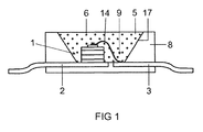
- FIG. 1 shows the construction of an RGB-based white light conversion LED as known per se.
- the light source is a semiconductor device comprising a blue-emitting InGaN chip 1 with a peak emission wavelength of 435 to 455 nm peak wavelength, for example 445 nm, embedded in an opaque base housing 8 in the region of a recess 9.
- the chip 1 is connected via a bonding wire 14 to a first terminal 3 and directly connected to a second electrical connection 2.
- the recess 9 is filled with a potting compound 5, which contains as main components a silicone (60-90 wt .-%) and phosphor pigments 6 (less than 40 wt .-%).
- a first phosphor is a green emitting garnet phosphor LuAGaG: Ce, and a red emitting aluminonitridosilicate CaAlSiN3: Eu.
- the recess has a wall 17, which serves as a reflector for the primary and secondary radiation from the chip 1 and the pigments 6.
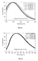
- FIG. 2 shows the temperature quenching behavior of various red emitting phosphors, which in principle work well with the chip FIG. 1 to be stimulated.
- the graph shows a comparison with other orange / red phosphors.
- Ca can be replaced in small amounts up to 20%, in particular up to 10%, by Ba, Sr, Mg, Li or Cu alone or in combination.
- Al component He can in small quantities, especially until 10%, to be replaced by B or O alone or in combination.
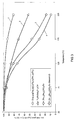
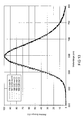
- FIG. 3 shows the temperature quenching behavior of various yellow-green emitting phosphor, which in principle works well with the chip FIG. 1 to be stimulated.
- the phosphor A3B5012 Ce in the embodiment with the preferred composition LuAGaG, ie Lu3 (Al, Ga) 5012: Ce with about 25% content of Ga for component B (preferred are 10-40% of Ga content, more preferably 15-25%). 30% Ga content) and about 2.2% Ce (preferred are 1.5-2.9% Ce, more preferably 1.8-2.6% Ce, in each case based on the proportion A), characterized by very low temperature quenching.
- a preferred phosphor is (Lu0.978Ce0.022) 3Al3.75Ga1.25012, see curve 1.
- the graph shows a comparison with other yellow and green phosphors, which show a much lower temperature quenching behavior.
- Orthosilicates curve 3,4 are completely unsuitable, but also YAGaG, ie Y3 (Al, Ga) 5012: Ce according to curve 2, is significantly worse.
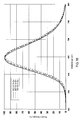
- FIG. 4 shows the stability of the yellow-green component.
- the stability of the green phosphor having the preferred composition was LuAGaG with about 25% Ga and about 2.2% Ce, (Lu0.978Ce0.022) 3Al3.75Ga1.25012) and compared with other known yellow / green emitting phosphors.
- the relative intensities of the blue LED peak and the phosphor peak were measured at the beginning and at the end, and from this the loss of conversion efficiency was determined.
- This LuAGaG phosphor is perfectly stable within the measuring errors (quadratic measuring points), while an orthosilicate under comparable conditions shows significant signs of aging (round measuring points).
- the color rendering of the warm white LED with the new phosphor mixture according to the invention shows a low dependence on the exciting blue LED wavelength used.
- a shift of the peak wavelength by 9 nm causes only a CRI loss (Ra8) of 3 points in the color reproduction.
- Typical other mixtures already lose 5 points in the blue with a difference of 7 nm peak wavelength (see Table 1).
- it is necessary to add a third phosphor which adversely affects efficiency and color steering.
- the dependence of the color rendering of saturated red is very greatly reduced, as is clear from the individual value for R9.
- Table 1 shows for the last two samples that in the range 435 nm to 445 nm peak wavelength of the exciting LED at a color temperature of 3000 to 3100 K outstanding Values of the CRI, namely Ra8 is at least 94 and the red index R9, at least 90, are possible. Tab.
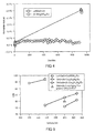
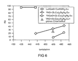
- FIG. 5 and 6 show the color rendering index (CRI) Ra8 and the red index R9 for different systems.
- the color rendering of the warm white LED with the new phosphor mixture according to the invention shows only a small dependence on the LED wavelength used.
- a shift of the blue wavelength by 9 nm only causes a CRI loss of 3 points.
- Typical other mixtures already lose at a difference 7 nm blue wavelength 5 points (see Table 1).
- the addition of a third phosphor is necessary, which adversely affects the efficiency and the color steering.
- FIG. 7 explains the cause of the low dependence of the color rendering index CRI of the blue wavelength:
- FIG. 8 shows the relative intensity with a shift of the phosphor spectrum of the green-yellow phosphor with variable excitation wavelength between 430 and 470 nm (Ex430 to 470) compared to YAGaG: Ce (FIG. FIG. 9 ) and yellow (Sr, Ba) Si2O2N2: Eu ( FIG. 10 ).
- the new green LuAGaG garnet behaves significantly differently than the comparative phosphors. It shows a strong green shift with decreasing excitation wavelength.
- the comparative phosphors remain approximately constant. Shown are the emission spectra of the three phosphors in comparison in LED applications interesting Range of excitation by a LED with peak wavelength between 430 and 470 nm. The curves of the FIG. 10 Virtually all are so close together that only one curve is visible.
- LuAGaG produces significantly higher color rendering values Ra8 and R9, see Table 2. This and the good excitability at short wavelengths make it possible for the first time to produce highly efficient, shortwave blue LEDs for warm white conversion LEDs for a color temperature be used from 2900 to 3150 K. Tab.
- a proportion Y provides up to about 30%, preferably with a proportion of 10 to 25%, a good supplement to Lu.
- the reason for this is the relatively similar ionic radius of Lu and Y.
- higher values of Y would shift the emission of the phosphor back into a range that would impair the desired overall system performance.
- Table 3 Various luminescent mixtures at about 3000 K in comparison (preferred solutions in bold); Peak stands for peak wavelength of the blue LED (nm); R9 denotes saturated red.
- FIG. 11 shows such a module 20 with various LEDs 24 on a base plate 21.
- a housing is mounted with side walls 22nd and a cover plate 12.
- the phosphor mixture is here as a layer 25 on both the side walls and especially on the cover plate 23, which is transparent, attached.
- the garnet according to the invention in addition to the predominant Lu as an essential component also shares in Y as cation A. These should be in the range up to a maximum of 32%.
- Other cations such as Tb, La, etc. are not categorically excluded as an adjunct, but due to their lack of adaptation to the system (Lu, Y), they should only be used in small amounts, preferably at most 5% of A, for any special adjustments to the properties of the phosphor be used.
- Suitable modified calsins are shown in Tab. 4. These are systems derived from the basic system CaAlSiN3: Eu. The elements O, F, Cl can replace a portion of the N. the element Cu can replace a proportion of Ca.
- FIG. 12 shows emission spectra for different calsines, in which N is partially replaced by small amounts of O, see Table 4.
- the O content should preferably not exceed 0.2 mol .-%.
- FIG. 13 shows emission spectra for different calsines, in which N is partially replaced by small amounts of Cl, see Table 4.
- the Cl content should preferably not exceed 0.05 mol .-%.
- FIG. 14 shows emission spectra for various calsins in which N is partially replaced by small amounts of F, see Table 4.
- the F content should preferably not exceed 0.05 mol%.
- FIG. 15 shows emission spectra for different calsines, in which Ca is partially replaced by small amounts of Cu, see Table 4. This allows a shift towards shorter wavelengths.
- the Cu content should preferably not exceed 0.05 mol%. The production succeeds here in the following way:
- the annealing is carried out under a flowing nitrogen atmosphere (2 L / min). At a rate of 250 K / h, the sample is heated to 1600 ° C, held there for 4 hours and cooled at 250K / h to room temperature.
- the resulting annealed cake is ground in a mortar mill and sieved over a 30 micron gauze.
- the screened material is again filled in the crucible and annealed again analogously to the first annealing.
- the resulting green cake is ground in a mortar mill and sieved over a 30 micron gauze.
- the screenings are the phosphor S 236.
- the annealing is carried out under a flowing nitrogen atmosphere. At a rate of 250 K / h, the sample is heated to 1600 ° C, held there for 4 hours and cooled at 250K / h to room temperature.
- the resulting annealed cake is ground in a mortar mill and sieved over a 30 micron gauze.
- the screened material is again filled in the crucible and annealed again analogously to the first annealing.
- the resulting green cake is ground in a mortar mill and sieved over a 30 micron gauze.
- the screening material is the phosphor S176.
- Figure. 16 shows emission spectra for various calsines in which the proportion of activator Eu has been varied. It turns out that the emission shifts to shorter wavelengths, the smaller the concentration of the activator is chosen. It lies between 0.3 and 0.5 mol .-%.
- FIG. 17 shows emission spectra for different grenades in which the proportion of Y has been varied. It turns out that the emission for Y small fraction remains almost constant.
- Tab. 4 shows pure LuAGAG phosphors with gradually increased Ga content. These table values, including the other tables, always refer to a reference excitation at 460 nm.
- Tab. 8 Lu (Al, Ga) garnet A3B5012: Ce (so-called LuAGAG) sample number Share Lu, rest Y Proportion Ga, balance Al x y lambda_dom / nm FWHM / nm rel.
Landscapes
- Chemical & Material Sciences (AREA)
- Engineering & Computer Science (AREA)
- Materials Engineering (AREA)
- Organic Chemistry (AREA)
- Ceramic Engineering (AREA)
- Inorganic Chemistry (AREA)
- Manufacturing & Machinery (AREA)
- Structural Engineering (AREA)
- Luminescent Compositions (AREA)
- Led Device Packages (AREA)
Description
- Die Erfindung geht aus von einer Konversions-LED gemäß dem Oberbegriff des Anspruchs 1. Derartige Konversions-LEDs sind insbesondere für Allgemeinbeleuchtung geeignet.
- Aus der
EP 1 696 016 ist eine Konversions-LED bekannt, die als roten Leuchtstoff ein Calsin verwendet. Eine weiße LED wird damit realisiert unter Verwendung einer blauen LED und einem gelben oder grünen Leuchtstoff ausgewählt als α -Sialon, Y2A15012:Ce oder (Y, Gd) 2 (Al, Ga) 5012 : Ce. - Aus der
EP-A 1 669 429 ist eine Konversions-LED bekannt, die zur Erzielung einer weißen LED einen blauen Chip zusammen mit speziellem Leuchtstoff des Typs (Sr,Ba)2Si5N8:Eu verwendet, wobei als zusätzlicher Leuchtstoff zur Verbesserung der Farbwiedergabe auch Lu-AG:Ce sowie ähnliche Leuchtstoffe, die mit Ce und Pr kodotiert sind, verwendet werden. - Die Aufgabe der vorliegenden Erfindung ist es, eine Konversions-LED bereitzustellen, die mit hoher Farbwiedergabe ausgestattet ist, wobei die Konversions-LED insbesondere eine hohe nutzbare Lebensdauer erreicht.
- Diese Aufgabe wird gelöst durch die kennzeichnenden Merkmale des Anspruchs 1.
- Besonders vorteilhafte Ausgestaltungen finden sich in den abhängigen Ansprüchen.
- Erfindungsgemäß wird jetzt eine Konversions-LED hoher Effizienz bereitgestellt. Nicht alle Leuchtstoffe sind in bei hohen Strömen, hier insbesondere mindestens 250 mA, bevorzugt mindestens 300 mA, besonders bevorzugt mindestens 350 mA, betriebenen LEDs, sog. Hochleistungs-LED, stabil. Insbesondere gilt diese Problematik für nitridische oder oxinitridische Leuchtstoffe wie das Nitridosilikat M2Si5N8:Eu. Viele derartige Leuchtstoffe, insbesondere Nitride des Typs M2Si5N8:D mit D als Aktivator erleiden beim Betrieb in einer LED deutliche Konversionsverluste. In kurzer Zeit (typisch 1000 Std.) verlieren derartige LEDs bis zu 50% Konversionseffizienz. Dies führt zu einer ausgeprägten Instabilität des Farborts.
- Weiße LEDs gewinnen in der Allgemeinbeleuchtung immer mehr an Bedeutung. Insbesondere steigt die Nachfrage nach warmweißen LEDs mit niedrigen Farbtemperaturen, bevorzugt im Bereich 2900 bis 3500 K, insbesondere 2900 bis 3100 K, und guter Farbwiedergabe, insbesondere Ra ist mindestens 93, bevorzugt mindestens 96, und gleichzeitig hoher Effizienz. Vor dem Hintergrund des kommenden Verbots der wenig energieeffizienten Allgebrauchsglühlampe gewinnen alternative Lichtquellen mit möglichst guter Farbwiedergabe (CRI) immer mehr an Bedeutung. Viele Verbraucher legen Wert auf Leuchtmittel mit glühlampenähnlichem Lichtspektrum.
- Gängige kommerziell erhältliche warmweiße LEDs bestehen in der Regel aus einer Kombination einer blauen LED mit gelben und roten Leuchtstoffen. Der Farbwiedergabeindex liegt typischerweise meist um 80. Deutlich bessere Farbwiedergabeindizes werden in der Regel durch die Zugabe weiterer Leuchtstoffe erreicht, was auf die Verarbeitung, Farbortstabilität und Effizienzen allerdings einen negativen Einfluss hat. Zur Kompensation der Blau-Grün-Lücke im Spektrum werden zudem meist sehr langwellige blaue LEDs eingesetzt (ca. 460nm). Seitens der Chiptechnologie ist es aus Effizienzgründen jedoch vorteilhaft, LEDs kürzerer Chipwellenlängen einzusetzen, die deutlich effizienter sind. Gewünscht sind Wellenlängen (Peak) von 430 bis 455 nm, insbesondere 435 bis 445 nm.
- Die Leuchtstoffe müssen eine Reihe von Anforderungen erfüllen: Eine sehr hohe Stabilität gegenüber chemischen Einflüssen, beispielsweise Sauerstoff, Feuchtigkeit, Wechselwirkungen mit Vergussmaterialien, sowie gegenüber Strahlung. Um einen stabilen Farbort bei steigender Systemtemperatur zu gewährleisten, sind außerdem Leuchtstoffe erforderlich, die ein sehr geringes Temperaturlöschverhalten aufweisen.
- Bisherige warmweiße LEDs mit sehr hohem CRI werden in der Regel erreicht durch die Kombination aus einer relativ langwelligen LED mit einem blau-grünen, einem grün-gelben und einem roten Leuchtstoff. Sowohl die Verwendung langwelliger LEDs als auch der Einsatz von drei Leuchtstoffen sind aus Applikationssicht und unter Effizienzgesichtspunkten ungünstig.
- Die neue Lösung besteht aus der Kombination aus einem neuartigen grünen Granatleuchtstoff und einem schmalbandigen roten Nitridoalumosilikat-Leuchtstoff. Der neue grüne Granatleuchtstoff zeigt gegenüber gebräuchlichen gelben (YAG) bzw. grüngelben (YAGaG) Granaten eine stark grünverschobene Emission auf, gleichzeitig ist das Anregungsoptimum stark kurzwellig verschoben.
- Die spektralen Eigenschaften der oben beschriebenen Leuchtstoffkombination erlauben die Realisierung warmweißer LEDs bis hin zu Lösungen für 2900 bis 3100 K mit extrem hohem CRI von 96 bis 98 bei gleichzeitig sehr guter Rotwiedergabe (R9=90 bis 99) in Verbindung mit blauen LED-Chips mit einer Peakwellenlänge von 440 bis 445 nm. Selbst bei Verwendung sehr kurzwelliger Chips (Peakwellenlänge 435 nm) werden noch sehr gute 95 CRI-Punkte erreicht. Die Beschränkung auf nur zwei konvertierende Leuchtstoffe vereinfacht die Verarbeitung in der LED stark und wirkt sich positiv auf die Farbortstabilität aus. Die beiden Leuchtstoffe der neuartigen Lösung zeigen eine sehr hohe Stabilität in LED-Alterungstests. Weiterhin zeichnen sich beide Leuchtstoffe durch ein sehr niedriges Temperaturlöschverhalten aus.
- Der entscheidende Fortschritt besteht jetzt darin, dass eine gleichzeitige Verbesserung mehrerer aus Applikationssicht zentraler Eigenschaften erreicht wurde, nämlich in Bezug auf Alterungsstabilität, Effizienz, verwendbarer Chipwellenlängenbereich und Temperaturstabilität der Leuchtstoffe. Der Unterschied dieser neuen Lösung gegenüber vorbekannten Warmweiß-Lösungen ist:
- Sehr stark grünverschobener, "intelligent" mit der LED-Wellenlänge schiebender Granatleuchtstoff. Dies bringt Vorteile in: CRI, Augenbewertung, Temperaturstabilität;
- kurze Chipwellenlänge. Dies bringt einen großen Vorteil im Hinblick auf hohe Effizienz;
- langwelliger, stabiler, aber gleichzeitig schmalbandiger, genau auf den Grünleuchtstoff abgestimmter Rotleuchtstoff. Dies bringt Vorteile in: LED-Lebensdauer (Effizienz, Farbortstabilität), relativ hohe Augenbewertung bei extrem guter Rotwiedergabe. Die volle Halbwertsbreite des schmalbandigen rot emittierenden Leuchtstoffs ist dabei bevorzugt kleiner als 90 nm FWHM erwünscht. Die volle Halbwertsbreite des schmalbandigen grün emittierenden Leuchtstoffs ist dabei bevorzugt kleiner als 115 nm FWHM erwünscht.
- Wesentliche Merkmale der Erfindung in Form einer numerierten Aufzählung sind:
- 1. Konversions-LED mit einem Chip, der primäre Strahlung emittiert, sowie einer dem Chip vorgelagerten Leuchtstoff enthaltenden Schicht, die mindestens einen Teil der primären Strahlung des Chips in sekundäre Strahlung konvertiert, wobei ein erster gelb-grün emittierender Leuchtstoff des Typs Granat A3B5012:Ce und ein zweiter orange-rot emittierender Leuchtstoff des Typs Calsin MAlSiN3:Eu verwendet wird, dadurch gekennzeichnet, dass die Peak-Wellenlänge der primären Strahlung im Bereich 435 bis 455 nm liegt, wobei der erste Leuchtstoff ein Granat mit im wesentlichen dem Kation A = Lu oder Lu in Kombination mit Y ist, und wobei B gleichzeitig Anteile von Al und Ga aufweist, während der zweite Leuchtstoff vom grundsätzlichen Typ MAl-SiN3:Eu ist, das Ca als M mit einem Anteil von mindestens 80%, insbesondere mindestens 90%, bevorzugt mindestens 95%, enthält, mit M ist Ca allein oder überwiegend Ca und Rest von M kann Sr, Ba, Mg, Li oder Cu sein, jeweils allein oder in Kombination, und wobei ein Teil des Al bis 20%, bevorzugt höchstens 5%, durch B, O, F, Cl, allein oder in Kombination ersetzt sein kann..
- 2. Konversions-LED nach Anspruch 1, dadurch gekennzeichnet, dass der erste Leuchtstoff 10 bis 40 Mol.-% Ga, insbesondere 20 bis 30%, bei der Komponente B enthält, Rest ist Al.
- 3. Konversions-LED nach Anspruch 1, dadurch gekennzeichnet, dass der erste Leuchtstoff 1,5 % bis 2,9 Mol.-% Ce, insbesondere 1,8 bis 2,6 Mol.-% Ce, als Dotierung, die der Komponente A zugerechnet ist, enthält, Rest ist A.
- 4. Konversions-LED nach Anspruch 1, dadurch gekennzeichnet, dass der zweite Leuchtstoff alleine Ca als Komponente M enthält.
- 5. Konversions-LED nach Anspruch 1, dadurch gekennzeichnet, dass der zweite Leuchtstoff 0,2 bis 1,3 Mol.-% Eu, insbesondere 0,3 bis 0,9 %, als Dotierung, die der Komponente M zugerechnet ist, enthält.
- 6. Konversions-LED nach Anspruch 1, dadurch gekennzeichnet, dass der zweite Leuchtstoff CaAlSiN3:Eu mit 0,3 bis 0,8 % Eu-Anteil von M ist.
- 7. Konversions-LED nach Anspruch 6, dadurch gekennzeichnet, dass der erste Leuchtstoff A3B5012 ist, mit A = 75 bis 100% Lu, Rest Y und einem Ce-Gehalt von 1,5 bis 2,5%, mit B = 10 bis 40 % Ga, Rest Al.
- 8. Konversions-LED nach Anspruch 7, dadurch gekennzeichnet, dass der erste Leuchtstoff A3B5012 ist, mit A = 80 bis 100% Lu, Rest Y und einem Ce-Gehalt von 1,5 bis 2,5%, mit B = 15 bis 25 % Ga, Rest Al.
- Im Folgenden soll die Erfindung anhand mehrerer Ausführungsbeispiele näher erläutert werden. Die Figuren zeigen:
- Fig. 1
- eine Konversions-LED;
- Fig. 2
- einen Vergleich der Temperaturabhängigkeit verschiedener rot emittierender Leuchtstoffe;
- Fig. 3
- einen Vergleich der Temperaturabhängigkeit verschiedener grün emittierender Leuchtstoffe;
- Fig. 4
- einen Vergleich der Zeitabhängigkeit der Konverter-Verluste für verschiedene Leuchtstoffe;
- Fig. 5
- einen Vergleich des CRI für verschiedene Leuchtstoffmischungen bei Wellenlängenverschiebung der Primäranregung;
- Fig.
- 6 einen Vergleich des R9 für verschiedene Leuchtstoffmischungen bei Wellenlängenverschiebung der Primäranregung;
- Fig. 7
- einen Vergleich der Gesamtemission einer Konversions-LED bei verschiedener Primäremission;
- Fig. 8-10
- einen Vergleich der Emission von LuAGaG bzw. YAGaG bzw. Misch-Sion bei verschiedener Peaklage der Primäremission (Ex);
- Fig. 11
- ein LED-Modul mit entfernt angebrachter Leuchtstoffmischung.
- Figur 12
- einen Vergleich der Emission bei Calsinen, die O enthalten;
- Figur 13
- einen Vergleich der Emission bei Calsinen, die Cl enthalten;
- Figur 14
- einen Vergleich der Emission bei Calsinen, die F enthalten;
- Figur 15
- einen Vergleich der Emission bei Calsinen, die Cu enthalten;
- Figur 16
- einen Vergleich der Emission bei Calsinen, die verschiedenen Gehalt an Eu enthalten;
- Figur 17
- einen Vergleich der Emission bei Lu-Granaten, die verschiedenen Gehalt an Y enthalten.
-
Figur 1 zeigt den Aufbau einer Konversions-LED für weißes Licht auf RGB-Basis wie an sich bekannt. Die Lichtquelle ist ein Halbleiterbauelement mit einem blau emittierende Chip 1 des Typs InGaN mit einer Peakemissionswellenlänge von 435 bis 455 nm Peakwellenlänge, beispielsweise 445 nm, das in ein lichtundurchlässiges Grundgehäuse 8 im Bereich einer Ausnehmung 9 eingebettet ist. Der Chip 1 ist über einen Bonddraht 14 mit einem ersten Anschluss 3 und direkt mit einem zweiten elektrischen Anschluss 2 verbunden. Die Ausnehmung 9 ist mit einer Vergussmasse 5 gefüllt, die als Hauptbestandteile ein Silikon (60- 90 Gew.-%) und Leuchtstoffpigmente 6 (weniger als 40 Gew.-%) enthält. Ein erster Leuchtstoff ist ein grün emittierender Granat-Leuchtstoff LuAGaG:Ce, sowie ein rot emittierendes Alumonitridosilikat CaAlSiN3:Eu. Die Ausnehmung hat eine Wand 17, die als Reflektor für die Primär- und Sekundärstrahlung vom Chip 1 bzw. den Pigmenten 6 dient. -
Figur 2 zeigt das Temperaturlöschungs-Verhalten verschiedener rot emittierender Leuchtstoffe, die sich im Prinzip gut mit dem Chip ausFigur 1 anregen lassen. Der neue tiefrote Leuchtstoff CaAlSiN3:Eu oder (Ca1-xEux)AlSiN3 zeichnet sich durch sehr geringe Temperaturlöschung aus. Dabei ist ein Anteil von 0,3% (x=0,003) bis 0,8% Eu (x=0,008) besonders gut geeignet. Allgemein ist bevorzugt ein Eu-Anteil an M=Ca von x = 0,002-0,012, besonders bevorzugt x = 0,003-0,009. Er zeichnet sich durch sehr geringe Temperaturlöschung aus, siehe Kurve 1. Die Grafik zeigt einen Vergleich mit anderen orange/roten Leuchtstoffen. Deutlich schlechter geeignet sind Nitridosilikate mit Ba oder Ca, siehe Kurve 2 und 3. Ungeeignet sind Orthosilikate (Kurve 4). Der Leuchtstoff CaAlSiN3:Eu (Farbkoordinaten CIE mit x/y = 0,657/0,341) lässt sich in der Regel auf vielfältige Weise für spezielle Anforderungen modifizieren, ohne dass sich die Emission entscheidend ändert. Dabei lässt sich Ca in kleinen Anteilen bis 20%, insbesondere bis 10%, durch Ba,Sr,Mg,Li oder Cu allein oder in Kombination ersetzen. Ähnliches gilt für den Al-Anteil. Er kann in kleinen Mengen, insbesondere bis 10%, durch B oder O allein oder in Kombination ersetzt sein. - Ein Beispiel eines modifizierten Leuchtstoffs (Ca0.892Mg0.1Eu0.008) (Al0.99B0.01) Si1N3 (CIE-x/y = 0,657/0340) vom grundsätzlichen Strukturtyp "CaAlSiN3:Eu" ist in Tabelle 3 angegeben. Weitere Modifikationen mit leicht geändertem Kationenverhältnis oder partieller Ca-Sr-Substitution ggf. zusammen mit einer partiellen O/N-Substitution - wie z. B. (Ca0.945Sr0.045 Eu0.01)AlSi(N2.9O0.1)- sind ebenfalls möglich.
-
Figur 3 zeigt das Temperaturlöschungs-Verhalten verschiedener gelb-grün emittierender Leuchtstoff, die sich im Prinzip gut mit dem Chip ausFigur 1 anregen lassen. Der Leuchtstoff A3B5012:Ce in der Ausführungsform mit der bevorzugten Zusammensetzung LuAGaG, also Lu3 (Al, Ga) 5012:Ce mit ca. 25% Anteil Ga für Komponente B (bevorzugt sind 10-40% Ga-Anteil, besonders bevorzugt sind 15-30% Ga-Anteil) und ca. 2,2% Ce (bevorzugt sind 1.5-2.9% Ce, besonders bevorzugt 1.8-2.6% Ce, jeweils bezogen auf den Anteil A), zeichnet sich durch sehr geringe Temperaturlöschung aus. Ein bevorzugter Leuchtstoff ist (Lu0.978Ce0.022) 3Al3.75Ga1.25012, siehe Kurve 1. Die Grafik zeigt einen Vergleich mit anderen gelben und grünen Leuchtstoffen, die ein wesentlich schlechteres Temperaturlöschungs-Verhalten zeigen. Orthosilikate (Kurve 3,4) sind völlig ungeeignet, aber auch YAGaG, also Y3(Al,Ga)5012:Ce gemäß Kurve 2, ist deutlich schlechter. -
Figur 4 zeigt die Stabilität der gelb-grün-Komponente. In einem LED-Alterungstest wurde die Stabilität des Grünleuchtstoffs mit der bevorzugten Zusammensetzung LuAGaG mit ca. 25% Ga und ca. 2,2% Ce, (Lu0.978Ce0.022) 3Al3.75Ga1.25012) ermittelt und mit anderen bekannten gelb/grün emittierenden Leuchtstoffen verglichen. Dabei wurde eine blaue Hochleistungs-LED (λpeak=435 nm) mit einer Dispersion des jeweiligen Leuchtstoffs in Silikon vergossen und diese bei 350 mA für 1000 h betrieben. Die relativen Intensitäten des blauen LED-Peaks sowie des Leuchtstoffpeaks wurden zum Beginn und zum Ende gemessen und daraus der Verlust der Konversionseffizienz bestimmt. Dieser LuAGaG-Leuchtstoff ist im Rahmen der Messfehler perfekt stabil (viereckige Messpunkte), während ein Orthosilikat unter vergleichbaren Bedingungen deutliche Alterungserscheinungen zeigt (runde Messpunkte). - Die Farbwiedergabe der warmweißen LED mit der erfindungsgemäßen neuen Leuchtstoffmischung (LuAGaG plus tiefrotes CaAlSiN3) zeigt eine geringe Abhängigkeit von der eingesetzten anregenden blauen LED-Wellenlänge. Eine Verschiebung der Peak-Wellenlänge um 9 nm bewirkt in der Farbwiedergabe nur einen CRI-Verlust (Ra8) von 3 Punkten. Typische andere Mischungen verlieren bereits bei einem Unterschied von 7 nm Peak-Wellenlänge im Blauen 5 Punkte (siehe Tabelle 1). Um dort dann den CRI-Verlust auf 1 Punkt zu verringern, ist die Zugabe eines dritten Leuchtstoffs nötig, was die Effizienz und das Colour-Steering negativ beeinflusst. Insbesondere wird auch die Abhängigkeit der Farbwiedergabe von gesättigtem Rot sehr stark verringert, wie am Einzelwert für R9 deutlich wird.
- Tab. 1 zeigt für die letzten beiden Muster, dass im Bereich 435 nm bis 445 nm Peakwellenlänge der anregenden LED bei einer Farbtemperatur von 3000 bis 3100 K herausragende Werte des CRI, nämlich Ra8 ist mindestens 94 und des Rot-Index R9, mindestens 90, möglich sind.
Tab. 1 Peak-Wellenlänge der blauen LED / nm Farbtemperatur /K Leuchtstoff 1 (grün-gelb) Leuchtstoff 2 (orange-rot) Leuchtstoff 3 (blau-grün) Verhältnis gelb:rot Farbwiedergabeindex Ra8 R9 462 3200 YAG:3%Ce (Sr,Ca) 2Si5N8: Eu (60% Sr) - 9:1 81 23 455 3250 YAG:3%Ce (Sr,Ca) 2Si5N8: Eu (60% Sr) - 10.3:1 76 8 455 3200 YAG:3%Ce (Sr,Ca) 2Si5N8: Eu (60% Sr) grünes Chlorosilikat 9:1 80 25 462 3250 YAGaG:4%Ce (25%Ga) (Sr,Ca) 2Si5N8: Eu (60% Sr) - 6.1:1 86 43 455 3250 YAGaG:4%Ce (25%Ga) (Sr,Ca) 2Si5N8: Eu (60% Sr) - 7:1 83 34 444 3200 YAGaG:4%Ce (25%Ga) (Sr,Ca) 2Si5N8: Eu (60% Sr) - 7:1 77 20 444 3050 LuAGaG:2.2%Ce (25%Ga) CaAlSiN3:Eu - 3.35:1 97 96 435 3025 LuAGaG:2.2%Ce (25%Ga) CaAlSiN3:Eu - 2:1 94 96 -
Figur 5 und6 zeigen den Farbwiedergabeindex (CRI) Ra8 sowie den Rot-Index R9 für verschiedene Systeme. Die Farbwiedergabe der warmweißen LED mit der erfindungsgemäßen neuen Leuchtstoffmischung (LuAGaG+tiefrotes CaAlSiN3) zeigt nur eine geringe Abhängigkeit von der eingesetzten LED-Wellenlänge. Eine Verschiebung der Blau-Wellenlänge um 9 nm bewirkt nur einen CRI-Verlust von 3 Punkten. Typische andere Mischungen verlieren bereits bei einem Unterschied von 7 nm Blau-Wellenlänge 5 Punkte (siehe Tabelle 1). Um dort den CRI-Verlust auf 1 Punkt zu verringern, ist die Zugabe eines dritten Leuchtstoffs nötig, was die Effizienz und das Colour-Steering negativ beeinflusst. - Insbesondere wird auch die Abhängigkeit der Farbwiedergabe von gesättigtem Rot sehr stark verringert, wie am Einzelwert für R9 deutlich wird, siehe
Figur 6 . -
Figur 7 erläutert die Ursache für die geringe Abhängigkeit des Farbwiedergabeindex CRI von der Blau-Wellenlänge: Die Leuchtstoff-Emission verschiebt sich beim erfindungsgemäßen System überraschend mit zunehmend kurzwelliger Anregungswellenlänge deutlich zu kurzen Wellenlängen hin, siehe den Bereich bei etwa 530 nm. Dadurch ergibt sich eine gewisse Kompensation im Gesamtspektrum: Die beim Einsatz einer kürzerwellig emittierenden LED fehlenden Blau-Grün-Anteile werden durch die verstärkten Blau-Grün-Anteile der verschobenen Leuchtstoffemission nahezu ausgeglichen. -
Figur 8 zeigt die relative Intensität bei einer Verschiebung des Leuchtstoffspektrums des Grün-gelb-Leuchtstoffs mit variabler Anregungswellenlänge zwischen 430 und 470 nm (Ex430 bis 470) im Vergleich zu YAGaG:Ce (Figur 9 ) und gelbem (Sr,Ba) Si2O2N2:Eu (Figur 10 ). - Überraschenderweise verhält sich der neue grüne LuAGaG-Granat deutlich anders als die Vergleichs-Leuchtstoffe. Er zeigt eine starke Grünverschiebung mit sinkender Anregungswellenlänge. Die Vergleichs-Leuchtstoffe bleiben etwa konstant. Gezeigt sind die Emissionsspektren der drei Leuchtstoffe im Vergleich im für LED-Anwendungen interessanten Bereich der Anregung durch eine LED mit Peak-Wellenlänge zwischen 430 und 470 nm. Die Kurven der
Figur 10 liegen praktisch alle so dicht übereinander, dass nur eine Kurve erkennbar ist. - Der Einsatz eines Lutetium-Granats wirkt sich insgesamt deutlich positiv auf die Farbwiedergabe aus. Im Vergleich mit Yttrium-Granaten mit ähnlicher Leuchtstoff-Emissionswellenlänge ergeben sich bei LuAGaG deutlich höhere Farbwiedergabewerte Ra8 und R9, siehe Tabelle 2. Dadurch und durch die gute Anregbarkeit bei kurzen Wellenlängen können erstmals hocheffiziente, kurzwellige blaue LEDs für warmweiße Konversions-LED für eine Farbtemperatur von 2900 bis 3150 K eingesetzt werden.
Tab. 2 Peak-Wellenlänge der blauen LED / nm Farbtemperatur /K Leuchtstoff 1 (grün-gelb) Leuchtstoff 2 (orange-rot) Verhältnis gelb:rot Ra8 R9 (tiefrot) 444 3050 YAGaG:40%Ga, 2%Ce CaAlSiN3:Eu 2.3:1 95 82 444 3000 LuAGaG:2.2%Ce, 25%Ga CaAlSiN3:Eu 2.55:1 98 96 444 3050 LuAGaG:2.2%Ce, 25%Ga CaAlSiN3:Eu 3.6:1 98 99 - Mit nur zwei Leuchtstoffen wird eine sehr hohe Farbwiedergabe erreicht, trotz kurzwelliger blauer LED im Bereich 435 bis 455 nm. Dabei ist die spezielle Abstimmung der beiden gewählten Leuchtstoffe aufeinander wichtig. Beispielsweise erhöht der Einsatz eines noch längerwellig emittierenden Rotleuchtstoffs vom Typ Nitridosilikat nicht den CRI-Wert oder den Wert für die Rotwiedergabe R9, sondern liefert schlechtere Werte. Der Einsatz von Y-Granaten führt nicht zu derart hohen Werten, die mit Lu-Granat realisierbar sind. Details verschiedener Mischungen finden sich in Tab. 3. Gd ist als wesentliche Komponente völlig ungeeignet und sollte, ebenso wie Tb oder La, höchstens zur Feinabstimmung in kleinen Mengen bis 5 Mol.-% der Komponente A zugesetzt werden. Dagegen liefert ein Anteil Y bis etwa 30%, bevorzugt mit einem Anteil 10 bis 25%, eine gute Ergänzung zu Lu. Ursache ist der relativ ähnliche Ionenradius von Lu und Y. Höhere Werte von Y würden die Emission des Leuchtstoffs aber wieder in einen Bereich verschieben, der die gewünschte Performance des Gesamtsystems beeinträchtigen würde.
Tabelle 3: Verschiedene Leuchtstottmischungen bei ca. 3000 K im Vergleich (bevorzugte Lösungen in Fettdruck); Peak steht für Peak-Wellenlänge der blauen LED (nm); R9 bezeichnet gesättigtes Rot. Peak nm Farbtemperatur / K Leuchtstoff 1 (grün-gelb) Leuchtstoff 2 rot) Verhältnis gelb:rot Ra8 R9 444 3050 YAGaG:40%Ga,2%Ce Ca0,94Eu0,02Li0,045A13,8Si8,2N1 8 2.2:1 89 66 444 3000 YAGaG:40%Ga,2%Ce Sr1,14Ca0,74Eu0,12Si5N8 9.4:1 89 62 444 3000 YAGaG:40%Ga,2%Ce Ca0,992EU0,008AlSiN3 3:1 94 83 444 3050 YAGaG:40%Ga,2%Ce Sr0.76Ba0.96Ca0.16Eu0.12Si5N8 9:1 84 32 444 3050 YAGaG:40%Ga,2%Ce Ca0,992Eu0,008AlSiN3 2.3:1 95 82 444 3000 LuAGaG:2.5%Ce,25%Ga Ca0,992Eu0,008AlSiN3 2.55:1 98 96 444 3050 LuAGaG:2.2%Ce,25%Ga Ca0,992Eu0,008AlSiN3 3.6:1 98 99 435 3025 LuAGaG:2.2%Ce,25%Ga Ca0,992Eu0,008AlSiN3 2:1 94 96 444 3000 LuAGaG:2.2%Ce,25%Ga Ca0.892Mg0.1Eu0.008A10.99B0.01S ilN3 3:1 97 94 - Grundsätzlich ist die Verwendung der Leuchtstoff-Mischung als Dispersion, als Dünnfilm etc. direkt auf der LED oder auch, wie an sich bekannt, auf einem separaten, der LED vorgeschalteten Träger möglich.
Figur 11 zeigt ein derartiges Modul 20 mit diversen LEDs 24 auf einer Grundplatte 21. Darüber ist ein Gehäuse montiert mit Seitenwänden 22 und einer Deckplatte 12. die Leuchtstoff-Mischung ist hier als Schicht 25 sowohl auf den Seitenwänden als auch vor allem auf der Deckplatte 23, die transparent ist, angebracht. - Grundsätzlich ist es nicht ausgeschlossen, dass der erfindungsgemäße Granat außer dem überwiegenden Lu als wesentliche Komponente auch Anteile an Y als Kation A aufweist. Diese sollten im Bereich bis maximal 32% liegen. Andere Kationen wie Tb, La etc. sind als Zusatz nicht kategorisch ausgeschlossen, sie sollten aber wegen ihrer mangelnden Anpassung an das System (Lu,Y) nur in kleinen Mengen, bevorzugt maximal 5% von A, für etwaige spezielle Anpassungen der Eigenschaften des Leuchtstoffs verwendet werden.
- Geeignete modifizierte Calsine sind in Tab. 4 gezeigt. Es handelt sich dabei um Systeme, die vom Grundsystem CaAlSiN3:Eu abstammen. Dabei können die Elemente O, F, Cl einen Anteil des N ersetzen. das Element Cu kann einen Anteil Ca ersetzen.
-
Figur 12 zeigt Emissionsspektren für verschiedene Calsine, bei denen N partiell durch kleine Mengen O ersetzt ist, siehe Tab. 4. Um die Halbwertsbreite nicht zu stark zu verbreitern, sollte der O-Anteil bevorzugt 0,2 Mol.-% nicht übersteigen. -
Figur 13 zeigt Emissionsspektren für verschiedene Calsine, bei denen N partiell durch kleine Mengen Cl ersetzt ist, siehe Tab. 4. Um die Halbwertsbreite nicht zu stark zu verbreitern, sollte der Cl-Anteil bevorzugt 0,05 Mol.-% nicht übersteigen. -
Figur 14 zeigt Emissionsspektren für verschiedene Calsine, bei denen N partiell durch kleine Mengen F ersetzt ist, siehe Tab. 4. Um die Halbwertsbreite nicht zu stark zu verbreitern, sollte der F-Anteil bevorzugt 0,05 Mol.-% nicht übersteigen. -
Figur 15 zeigt Emissionsspektren für verschiedene Calsine, bei denen Ca partiell durch kleine Mengen Cu ersetzt ist, siehe Tab. 4. Damit lässt sich eine Verschiebung zu kürzeren Wellenlängen hin erreichen. Um die Effizienzverluste aufgrund von Gitterverzerrungen nicht zu stark werden zu lassen, sollte der Cu-Anteil bevorzugt 0,05 Mol.-% nicht übersteigen. Die Herstellung gelingt hier auf folgende Weise:
- Alle Ausgangsmaterialien werden innerhalb der Glovebox eingewogen und in einer Kugelmühle 6 Stunden homogenisiert. Das Gemisch wird locker in einen dicht schließenden Tiegel aus Molybdän gefüllt und in einen Hochtemperatur-Rohrofen überführt.
- Die Glühung wird unter fließender Stickstoff-Atmosphäre durchgeführt (2L/min). Mit einer Geschwindigkeit von 250 K/h wird die Probe auf 1600°C aufgeheizt, dort 4 Stunden gehalten und mit ebenfalls 250K/h auf Raumtemperatur abgekühlt.
- Der resultierende Glühkuchen wird in einer Mörsermühle gemahlen und über einer 30 µm-Gaze gesiebt. Das Siebgut wird wieder in den Tiegel gefüllt und nochmals analog zur ersten Glühung getempert.
- Der entstehende Glühkuchen wird in einer Mörsermühle gemahlen und über einer 30 µm-Gaze gesiebt. Das Siebgut ist der Leuchtstoff S 236.
- Die Herstellung von Calsin als Sample S176 ist in Tab. 6 gezeigt.

- Alle Ausgangsmaterialien werden innerhalb der Glovebox eingewogen und in einer Kugelmühle 6 Stunden homogenisiert. Das Gemisch wird locker in einen dicht schließenden Tiegel aus Molybdän gefüllt und in einen Hochtemperatur-Rohrofen überführt.
- Die Glühung wird unter fließender Stickstoff-Atmosphäre durchgeführt. Mit einer Geschwindigkeit von 250 K/h wird die Probe auf 1600°C aufgeheizt, dort 4 Stunden gehalten und mit ebenfalls 250K/h auf Raumtemperatur abgekühlt.
- Der resultierende Glühkuchen wird in einer Mörsermühle gemahlen und über einer 30 µm-Gaze gesiebt. Das Siebgut wird wieder in den Tiegel gefüllt und nochmals analog zur ersten Glühung getempert.
- Der entstehende Glühkuchen wird in einer Mörsermühle gemahlen und über einer 30 µm-Gaze gesiebt. Das Siebgut ist der Leuchtstoff S176.
-
Figur. 16 zeigt Emissionsspektren für verschiedene Calsine, bei denen der Anteil des Aktivators Eu variiert wurde. Es zeigt sich, dass die Emission sich zu kürzeren Wellenlängen hin verschiebt, je kleiner die Konzentration des Aktivators gewählt ist. Sie liegt hier zwischen 0,3 und 0,5 Mol.-%. - Tab. 7 zeigt verschiedene Granate aus dem System A3B5012:Ce mit A ausgewählt aus (Lu,Y). Dabei zeigt sich, dass für A=Lu bis hin zu A= 70%Lu, Rest Y gute Werte erzielt werden können. Gleichzeitig muss für Komponenten B das Verhältnis zwischen Al und Ga sorgfältig gewählt werden. Der Anteil Ga sollte zwischen 10 und 40 Mol.-%, insbesondere 10 bis 25% liegen. Dabei sind in Tab. 7 verschiedene (Lu,Y)-Granate A3B5012:Ce gezeigt, wobei die Konzentration des Aktivators Ce jeweils 2% von A beträgt und A = Lu,Y (angegeben ist der Anteil des Lu, Rest ist Y) sowie B= Al, Ga (angegeben ist der Anteil Ga, Rest ist Al) gewählt ist.
-
Figur 17 zeigt Emissionsspektren für verschiedene Granate, bei denen der Anteil des Y variiert wurde. Es zeigt sich, dass die Emission für kleine Anteil Y nahezu konstant bleibt. - Tab. 4 zeigt reine LuAGAG-Leuchtstoffe mit schrittweise erhöhtem Ga-Anteil. Diese Tabellenwerte, auch der anderen Tabellen, beziehen sich grundsätzlich immer auf eine Referenzanregung bei 460 nm.
Tab. 8: Lu(Al,Ga)-Granate A3B5012:Ce (sog. LuAGAG) Probennummer Anteil Lu, Rest Y Anteil Ga, Rest Al x y lambda_dom / nm FWHM / nm rel. QE SL 315c/08 100% 5,0% 0,350 0,567 557,5 109,1 1,00 SL 005c/09 100% 15,0% 0,337 0,572 555,1 104,3 1,01 SL 003c/09 100% 20,0% 0,351 0,564 557,7 108,4 1,05 SL 167c/08 100% 25,0% 0,352 0,562 557,9 109,8 1,05 Tab. 7: (Lu,Y)-Granate A3B5012:Ce Probennummer Anteil Lu, Rest Y Anteil Ga, Rest Al x y lambda_dom / nm FWHM / nm rel. QE SL 299c/08 100% 0,0% 0,393 0,557 564,2 112,5 1,00 SL 290c/08 88% 2,5% 0,396 0,556 564,6 113,2 1,02 SL 291c/08 68% 2,5% 0,414 0,550 567,1 115,4 1,01 SL 292c/08 78% 5,0% 0,400 0,555 565,2 113,7 1,01 SL 293c/08 78% 5,0% 0,400 0,556 565,1 114,3 1,01 SL 294c/08 78% 5,0% 0,401 0,555 565,3 114,8 1,02 SL 295c/08 78% 5,0% 0,401 0,555 565,3 113,8 1,02 SL 296c/08 88% 7,5% 0,388 0,559 563,5 112,8 1,02 SL 297c/08 68% 7,5% 0,402 0,555 565,4 114,4 1,03 SL 308c/08 88% 10,0% 0,383 0,560 562,8 112,1 1,03 SL 309c/08 83% 10,0% 0,387 0,559 563,3 112,5 1,03 SL 310c/08 83% 15,0% 0,381 0,560 562,5 113,0 1,03 SL 311c/08 78% 15,0% 0,385 0,559 563,1 112,3 1,02 Sample Summenformel ZusatzElement (x) Mol (Zus-Elem.) rel. Q.E. x y λ dom FWHM 176 CaAlSiN3:Eu+2 (0,5%) nein ---- 100,0% 0,664 0,332 610,7 87,3 180 CaAl1-xSi1+xN3-xOx:Eu+2 (0,5%) O 0,020 103,9% 0,660 0,335 609,7 88,2 181 CaAl1-xSi1+xN3-xOx:Eu+2 (0,5%) O 0,060 103,3% 0,658 0,338 608,8 88,4 182 CaAl1-xSi1+xN3-xOx:Eu+2 (0,5%) O 0,200 93,7% 0,634 0,358 603,2 90,2 183 CaAl1-xSi1+xN3-xOx:Eu+2 (0,5%) O 0,600 77,7% 0,583 0,406 592,8 104,4 187 CaAl1+2xSi1-2xN3-xClx:Eu+2 (0,5%) Cl 0,005 100,4% 0,664 0,332 610,7 87,3 188 CaAl1+2xSi1-2xN3-xClx:Eu+2 (0,5%) Cl 0,020 100,5% 0,666 0,330 611,3 86,7 189 CaAl1+2xSi1-2xN3-xClx:Eu+2 (0,5%) Cl 0,030 101,4% 0,664 0,331 611,0 87,6 190 CaAl1+2xSi1-2xN3-xClx:Eu+2 (0,5%) Cl 0,050 101,2% 0,659 0,336 609,4 88,5 191 CaAl1+2xSi1-2xN3-xFx:Eu+2 (0,5%) F 0,005 103,8% 0,670 0,327 612,4 87,0 192 CaAl1+2xSi1-2xN3-xFx:Eu+2 (0,5%) F 0,010 101,4% 0,670 0,326 612,7 86,9 193 CaAl1+2xSi1-2xN3-xFx:Eu+2 (0,5%) F 0,020 101,9% 0,668 0,327 612,4 87,2 194 CaAl1+2xSi1-2xN3-xFx:Eu+2 (0,5%) F 0,050 99,5% 0,662 0,333 610,3 87,0 Tab. 4: die Konzentration an Eu ist 0,5% bezogen auf M (hier Ca bzw Ca und Cu) 235 (Ca1-xCuxAl1+4xSi1-4xN3-2xF2x:Eu(0.5%) Cu, F 0,005 93,3% 0,665 0,332 610,7 86,4 236 (Ca1-xCuxAl1+4xSi1-4xN3-2xF2x:Eu(0.5%) Cu, F 0,012 93,5% 0,661 0,335 609,7 87,4 237 (Ca1-xCuxAl1+4xSi1-4xN3-2xF2x:Eu(0.5%) Cu, F 0,050 86,9% 0, 640 0,354 604,2 91,5
Claims (8)
- Konversions-LED mit einem Chip, der primäre Strahlung emittiert, sowie einer dem Chip vorgelagerten Leuchtstoff enthaltenden Schicht, die mindestens einen Teil der primären Strahlung des Chips in sekundäre Strahlung konvertiert, wobei ein erster gelb-grün emittierender Leuchtstoff des Typs Granat A3B5012:Ce und ein zweiter orange-rot emittierender Leuchtstoff des Typs Calsin MAlSiN3:Eu verwendet wird, dadurch gekennzeichnet, dass die Peak-Wellenlänge der primären Strahlung im Bereich 435 bis 455 nm liegt, wobei der erste Leuchtstoff ein Granat mit dem Kation A = Lu oder Lu in Kombination mit Y ist, und wobei B gleichzeitig Anteile von Al und Ga aufweist, während der zweite Leuchtstoff MAl-SiN3:Eu ist, das Ca als M mit einem Anteil von mindestens 80%, insbesondere mindestens 90%, bevorzugt mindestens 95%, enthält, mit M ist Ca allein oder überwiegend Ca und Rest von M kann Sr, Ba, Mg, Li oder Cu sein, jeweils allein oder in Kombination, und wobei ein Teil des Al bis 20%, bevorzugt höchstens 5%, durch B, O, F, Cl, allein oder in Kombination ersetzt sein kann..
- Konversions-LED nach Anspruch 1, dadurch gekennzeichnet, dass der erste Leuchtstoff 10 bis 40 Mol.-% Ga, insbesondere 20 bis 30%, bei der Komponente B enthält, Rest ist Al.
- Konversions-LED nach Anspruch 1, dadurch gekennzeichnet, dass der erste Leuchtstoff 1,5 % bis 2,9 Mol.-% Ce, insbesondere 1,8 bis 2,6 Mol.-% Ce, als Dotierung, die der Komponente A zugerechnet ist, enthält, Rest ist A.
- Konversions-LED nach Anspruch 1, dadurch gekennzeichnet, dass der zweite Leuchtstoff alleine Ca als Komponente M enthält.
- Konversions-LED nach Anspruch 1, dadurch gekennzeichnet, dass der zweite Leuchtstoff 0,2 bis 1,3 Mol.-% Eu, insbesondere 0,3 bis 0,9 %, als Dotierung, die der Komponente M zugerechnet ist, enthält.
- Konversions-LED nach Anspruch 1, dadurch gekennzeichnet, dass der zweite Leuchtstoff CaAlSiN3:Eu mit 0,3 bis 0,8 % Eu-Anteil von M ist.
- Konversions-LED nach Anspruch 6, dadurch gekennzeichnet, dass der erste Leuchtstoff A3B5012 ist, mit A = 75 bis 100% Lu, Rest Y und einem Ce-Gehalt von 1,5 bis 2,5%, mit B = 10 bis 40 % Ga, Rest Al.
- Konversions-LED nach Anspruch 7, dadurch gekennzeichnet, dass der erste Leuchtstoff A3B5012 ist, mit A = 80 bis 100% Lu, Rest Y und einem Ce-Gehalt von 1,5 bis 2,5%, mit B = 15 bis 25 % Ga, Rest Al.
Applications Claiming Priority (2)
| Application Number | Priority Date | Filing Date | Title |
|---|---|---|---|
| DE102009037730A DE102009037730A1 (de) | 2009-08-17 | 2009-08-17 | Konversions-LED mit hoher Farbwiedergabe |
| PCT/EP2010/061694 WO2011020756A1 (de) | 2009-08-17 | 2010-08-11 | Konversions-led mit hoher farbwiedergabe |
Publications (2)
| Publication Number | Publication Date |
|---|---|
| EP2467446A1 EP2467446A1 (de) | 2012-06-27 |
| EP2467446B1 true EP2467446B1 (de) | 2013-07-10 |
Family
ID=43127215
Family Applications (1)
| Application Number | Title | Priority Date | Filing Date |
|---|---|---|---|
| EP10743107.4A Active EP2467446B1 (de) | 2009-08-17 | 2010-08-11 | Konversions-led mit hoher farbwiedergabe |
Country Status (8)
| Country | Link |
|---|---|
| US (2) | US9234132B2 (de) |
| EP (1) | EP2467446B1 (de) |
| JP (1) | JP5431588B2 (de) |
| KR (1) | KR101728005B1 (de) |
| CN (2) | CN102471682A (de) |
| DE (1) | DE102009037730A1 (de) |
| TW (1) | TWI533480B (de) |
| WO (1) | WO2011020756A1 (de) |
Families Citing this family (28)
| Publication number | Priority date | Publication date | Assignee | Title |
|---|---|---|---|---|
| DE102009037730A1 (de) | 2009-08-17 | 2011-02-24 | Osram Gesellschaft mit beschränkter Haftung | Konversions-LED mit hoher Farbwiedergabe |
| DE102009055185A1 (de) * | 2009-12-22 | 2011-06-30 | Osram Gesellschaft mit beschränkter Haftung, 81543 | Leuchtstoff und Lichtquelle mit derartigen Leuchtstoff |
| DE102010021341A1 (de) * | 2010-05-22 | 2011-11-24 | Merck Patent Gmbh | Leuchtstoffe |
| US8747697B2 (en) * | 2011-06-07 | 2014-06-10 | Cree, Inc. | Gallium-substituted yttrium aluminum garnet phosphor and light emitting devices including the same |
| DE102011078402A1 (de) | 2011-06-30 | 2013-01-03 | Osram Ag | Konversionselement und Leuchtdiode mit einem solchen Konversionselement |
| WO2013018041A1 (en) * | 2011-08-04 | 2013-02-07 | Koninklijke Philips Electronics N.V. | Light converter and lighting unit comprising such light converter |
| DE102011113498A1 (de) * | 2011-09-15 | 2013-03-21 | Osram Opto Semiconductors Gmbh | Leuchtstoffmischung, optoelektronisches Bauelement mit einer Leuchtstoffmischung und Straßenlaterne mit einer Leuchtstoffmischung |
| DE102011115879A1 (de) * | 2011-10-12 | 2013-04-18 | Osram Opto Semiconductors Gmbh | Optoelektronisches Bauelement und Leuchtstoffe |
| DE102013217055B4 (de) | 2013-05-17 | 2022-08-25 | Tridonic Gmbh & Co Kg | Weisslicht-LED-Modul zur Objektbeleuchtung |
| CN103351863B (zh) * | 2013-07-08 | 2015-10-28 | 江苏博睿光电有限公司 | 一种红色荧光粉及其制备方法 |
| JP6036728B2 (ja) * | 2014-02-28 | 2016-11-30 | 信越化学工業株式会社 | 照明装置 |
| DE102014108004A1 (de) * | 2014-06-06 | 2015-12-17 | Osram Opto Semiconductors Gmbh | Verfahren zum Herstellen eines optoelektronischen Bauelements und optoelektronisches Bauelement |
| US9150784B1 (en) * | 2014-10-30 | 2015-10-06 | Osram Opto Semiconductors Gmbh | Lighting modules, lighting apparatus and electronic devices |
| KR102458539B1 (ko) * | 2014-11-14 | 2022-10-25 | 루미리즈 홀딩 비.브이. | 나비넥타이 형상의 a2n6 구성 요소를 포함하는 led 인광체 |
| CN107004751B (zh) * | 2014-11-28 | 2019-05-03 | 夏普株式会社 | 发光装置以及照明器具 |
| EP3229280A4 (de) | 2014-12-05 | 2018-06-06 | Sharp Kabushiki Kaisha | Lichtemittierende vorrichtung und leuchte |
| JP6354626B2 (ja) * | 2015-03-09 | 2018-07-11 | 豊田合成株式会社 | 発光装置の製造方法 |
| DE102015120775B4 (de) * | 2015-11-30 | 2025-04-30 | OSRAM Opto Semiconductors Gesellschaft mit beschränkter Haftung | Optoelektronisches Bauelement und Hintergrundbeleuchtung für ein Display |
| DE102016104369A1 (de) * | 2016-03-10 | 2017-09-14 | Osram Opto Semiconductors Gmbh | Leuchtstoffmischung und optoelektronisches Bauelement mit einer Leuchtstoffmischung |
| US11851596B2 (en) | 2016-08-12 | 2023-12-26 | Osram Oled Gmbh | Lighting device |
| DE102016121692A1 (de) | 2016-08-12 | 2018-02-15 | Osram Gmbh | Leuchtstoff und Verfahren zur Herstellung eines Leuchtstoffs |
| WO2019029849A1 (de) * | 2016-11-11 | 2019-02-14 | Osram Opto Semiconductors Gmbh | Dimmbare lichtquelle |
| CN108690618A (zh) * | 2017-04-01 | 2018-10-23 | 江苏博睿光电有限公司 | 一种荧光粉及其制备方法和发光器件 |
| US11215339B2 (en) * | 2017-05-02 | 2022-01-04 | Signify Holding B.V. | Warm white LED spectrum especially for retail applications |
| DE102017122996A1 (de) * | 2017-10-04 | 2019-04-04 | Osram Opto Semiconductors Gmbh | Leuchtstoffmischung, Konversionselement und optoelektronisches Bauelement |
| JP6773018B2 (ja) | 2017-12-26 | 2020-10-21 | 日亜化学工業株式会社 | 発光装置 |
| DE102018101428A1 (de) * | 2018-01-23 | 2019-07-25 | Osram Opto Semiconductors Gmbh | Optoelektronisches Bauelement |
| DE102018123010A1 (de) | 2018-09-19 | 2020-03-19 | Osram Opto Semiconductors Gmbh | Strahlungsemittierendes bauelement |
Family Cites Families (18)
| Publication number | Priority date | Publication date | Assignee | Title |
|---|---|---|---|---|
| JP4991026B2 (ja) * | 2003-02-26 | 2012-08-01 | 日亜化学工業株式会社 | 発光装置 |
| JP3837588B2 (ja) * | 2003-11-26 | 2006-10-25 | 独立行政法人物質・材料研究機構 | 蛍光体と蛍光体を用いた発光器具 |
| JP4511849B2 (ja) * | 2004-02-27 | 2010-07-28 | Dowaエレクトロニクス株式会社 | 蛍光体およびその製造方法、光源、並びにled |
| TWI262609B (en) * | 2004-02-27 | 2006-09-21 | Dowa Mining Co | Phosphor and manufacturing method thereof, and light source, LED using said phosphor |
| US7671529B2 (en) | 2004-12-10 | 2010-03-02 | Philips Lumileds Lighting Company, Llc | Phosphor converted light emitting device |
| WO2006080535A1 (ja) * | 2005-01-31 | 2006-08-03 | Ube Industries, Ltd. | 窒化物赤色蛍光体およびその製造方法 |
| CN101128563B (zh) * | 2005-02-28 | 2012-05-23 | 三菱化学株式会社 | 荧光体、其制造方法及其应用 |
| US20060255712A1 (en) * | 2005-04-19 | 2006-11-16 | Masatsugu Masuda | Light emitting apparatus, liquid crystal display apparatus and lighting apparatus |
| JP2007049114A (ja) * | 2005-05-30 | 2007-02-22 | Sharp Corp | 発光装置とその製造方法 |
| DE102006036577A1 (de) * | 2006-08-04 | 2008-02-07 | Patent-Treuhand-Gesellschaft für elektrische Glühlampen mbH | Rot emittierender Leuchtstoff und Lichtquelle mit derartigem Leuchtstoff |
| US8178001B2 (en) * | 2007-04-18 | 2012-05-15 | Mitsubishi Chemical Corporation | Method for producing inorganic compound, phosphor, phosphor-containing composition, light-emitting device, lighting system, and display device |
| WO2009025469A2 (en) | 2007-08-22 | 2009-02-26 | Seoul Semiconductor Co., Ltd. | Non stoichiometric tetragonal copper alkaline earth silicate phosphors and method of preparing the same |
| US8030839B2 (en) * | 2007-11-30 | 2011-10-04 | Nichia Corporation | Phosphor activated with europium, light emitting device using the same and method of manufacturing the phosphor |
| RU2010132369A (ru) | 2008-01-03 | 2012-02-10 | Конинклейке Филипс Электроникс Н.В. (Nl) | Устройство отображения и осветительное устройство |
| KR100937962B1 (ko) | 2008-02-01 | 2010-01-21 | 삼성에스디아이 주식회사 | 디스플레이 장치용 형광체 조성물 |
| US20090283721A1 (en) * | 2008-05-19 | 2009-11-19 | Intematix Corporation | Nitride-based red phosphors |
| US7888691B2 (en) * | 2008-08-29 | 2011-02-15 | Koninklijke Philips Electronics N.V. | Light source including a wavelength-converted semiconductor light emitting device and a filter |
| DE102009037730A1 (de) | 2009-08-17 | 2011-02-24 | Osram Gesellschaft mit beschränkter Haftung | Konversions-LED mit hoher Farbwiedergabe |
-
2009
- 2009-08-17 DE DE102009037730A patent/DE102009037730A1/de not_active Withdrawn
-
2010
- 2010-08-11 JP JP2012525135A patent/JP5431588B2/ja not_active Expired - Fee Related
- 2010-08-11 KR KR1020127006991A patent/KR101728005B1/ko active Active
- 2010-08-11 WO PCT/EP2010/061694 patent/WO2011020756A1/de not_active Ceased
- 2010-08-11 CN CN2010800366658A patent/CN102471682A/zh active Pending
- 2010-08-11 CN CN201610817559.2A patent/CN107068837A/zh active Pending
- 2010-08-11 EP EP10743107.4A patent/EP2467446B1/de active Active
- 2010-08-11 US US13/391,197 patent/US9234132B2/en active Active
- 2010-08-16 TW TW099127266A patent/TWI533480B/zh not_active IP Right Cessation
-
2015
- 2015-12-31 US US14/985,644 patent/US10020429B2/en active Active
Also Published As
| Publication number | Publication date |
|---|---|
| CN102471682A (zh) | 2012-05-23 |
| TW201123551A (en) | 2011-07-01 |
| US20120146079A1 (en) | 2012-06-14 |
| US9234132B2 (en) | 2016-01-12 |
| TWI533480B (zh) | 2016-05-11 |
| DE102009037730A1 (de) | 2011-02-24 |
| KR20120062791A (ko) | 2012-06-14 |
| US10020429B2 (en) | 2018-07-10 |
| KR101728005B1 (ko) | 2017-04-18 |
| JP5431588B2 (ja) | 2014-03-05 |
| CN107068837A (zh) | 2017-08-18 |
| EP2467446A1 (de) | 2012-06-27 |
| US20160111609A1 (en) | 2016-04-21 |
| WO2011020756A1 (de) | 2011-02-24 |
| JP2013502711A (ja) | 2013-01-24 |
Similar Documents
| Publication | Publication Date | Title |
|---|---|---|
| EP2467446B1 (de) | Konversions-led mit hoher farbwiedergabe | |
| EP2467447B1 (de) | Konversions-led mit hoher effizienz | |
| DE102006007799B4 (de) | Licht emittierendes Halbleiterbauteil | |
| DE112007001638B4 (de) | Leuchtstoff aus der Klasse der Nitridosilikate, Verfahren zur Herstellung eines Leuchtstoff aus der Klasse der Nitridosilikate und Verwendung eines derartigen Leuchtstoffs in einer Lichtquelle | |
| DE112017002922B4 (de) | Fluoreszierendes pulver, herstellungsverfahren dafür und leuchtende vorrichtung mit diesem fluoreszierenden pulver | |
| DE10360546A1 (de) | Leuchtstoff und Lichtquelle mit derartigem Leuchtstoff | |
| DE102007035592A1 (de) | Temperaturstabiler Leuchtstoff und Lichtquelle mit derartigem Leuchtstoff | |
| WO2010020495A1 (de) | Alpha-sialon-leuchtstoff | |
| WO2007096333A1 (de) | Leuchtstoff und lichtquelle mit derartigem leuchststoff sowie herstellverfahren für den leuchtstoff | |
| EP2718396B9 (de) | Beleuchtungseinheit | |
| DE102004038199A1 (de) | LED mit niedriger Farbtemperatur | |
| DE102006041119A1 (de) | Leuchtstoff und Licht emittierendes Bauteil | |
| DE102005005263A1 (de) | Gelb emittierender Leuchtstoff und Lichtquelle mit derartigem Leuchtstoff | |
| WO2005030905A1 (de) | Hocheffizienter leuchtstoff | |
| DE102011113498A1 (de) | Leuchtstoffmischung, optoelektronisches Bauelement mit einer Leuchtstoffmischung und Straßenlaterne mit einer Leuchtstoffmischung | |
| DE102011014958B4 (de) | Gelblicht emittierende Fluorosulfidleuchtstoffe und deren Herstellungsverfahren, sowie eine diesen Leuchtstoff umfassende Weißlicht emittierende Diode | |
| EP2217678B1 (de) | Leuchtstoff und beleuchtungssystem mit derartigem leuchtstoff | |
| DE102018004827B4 (de) | Gelber leuchtstoff und beleuchtungsvorrichtung | |
| WO2009077277A1 (de) | Konversions-led | |
| EP2491095B1 (de) | Leuchtstoff und lichtquelle mit derartigem leuchtstoff | |
| WO2024078931A1 (de) | Leuchtstoff, verfahren zur herstellung eines leuchtstoffs und strahlungsemittierendes bauelement | |
| DE102005037455A1 (de) | Weißlicht-Leuchtdiode | |
| DE102019208285A1 (de) | Gelber leuchtstoff und lichtquelle |
Legal Events
| Date | Code | Title | Description |
|---|---|---|---|
| PUAI | Public reference made under article 153(3) epc to a published international application that has entered the european phase |
Free format text: ORIGINAL CODE: 0009012 |
|
| 17P | Request for examination filed |
Effective date: 20120123 |
|
| AK | Designated contracting states |
Kind code of ref document: A1 Designated state(s): AL AT BE BG CH CY CZ DE DK EE ES FI FR GB GR HR HU IE IS IT LI LT LU LV MC MK MT NL NO PL PT RO SE SI SK SM TR |
|
| DAX | Request for extension of the european patent (deleted) | ||
| REG | Reference to a national code |
Ref country code: DE Ref legal event code: R079 Ref document number: 502010003979 Country of ref document: DE Free format text: PREVIOUS MAIN CLASS: C09K0011080000 Ipc: C09K0011590000 |
|
| RAP1 | Party data changed (applicant data changed or rights of an application transferred) |
Owner name: OSRAM GMBH Owner name: OSRAM OPTO SEMICONDUCTORS GMBH |
|
| GRAP | Despatch of communication of intention to grant a patent |
Free format text: ORIGINAL CODE: EPIDOSNIGR1 |
|
| RIC1 | Information provided on ipc code assigned before grant |
Ipc: C04B 35/584 20060101ALI20130128BHEP Ipc: C09K 11/59 20060101AFI20130128BHEP Ipc: C04B 35/581 20060101ALI20130128BHEP Ipc: C09K 11/80 20060101ALI20130128BHEP |
|
| RAP1 | Party data changed (applicant data changed or rights of an application transferred) |
Owner name: OSRAM OPTO SEMICONDUCTORS GMBH Owner name: OSRAM GMBH |
|
| GRAS | Grant fee paid |
Free format text: ORIGINAL CODE: EPIDOSNIGR3 |
|
| GRAA | (expected) grant |
Free format text: ORIGINAL CODE: 0009210 |
|
| AK | Designated contracting states |
Kind code of ref document: B1 Designated state(s): AL AT BE BG CH CY CZ DE DK EE ES FI FR GB GR HR HU IE IS IT LI LT LU LV MC MK MT NL NO PL PT RO SE SI SK SM TR |
|
| REG | Reference to a national code |
Ref country code: GB Ref legal event code: FG4D Free format text: NOT ENGLISH |
|
| REG | Reference to a national code |
Ref country code: AT Ref legal event code: REF Ref document number: 621002 Country of ref document: AT Kind code of ref document: T Effective date: 20130715 Ref country code: CH Ref legal event code: EP |
|
| REG | Reference to a national code |
Ref country code: IE Ref legal event code: FG4D Free format text: LANGUAGE OF EP DOCUMENT: GERMAN |
|
| REG | Reference to a national code |
Ref country code: DE Ref legal event code: R096 Ref document number: 502010003979 Country of ref document: DE Effective date: 20130905 |
|
| PG25 | Lapsed in a contracting state [announced via postgrant information from national office to epo] |
Ref country code: SI Free format text: LAPSE BECAUSE OF FAILURE TO SUBMIT A TRANSLATION OF THE DESCRIPTION OR TO PAY THE FEE WITHIN THE PRESCRIBED TIME-LIMIT Effective date: 20130710 |
|
| REG | Reference to a national code |
Ref country code: NL Ref legal event code: T3 |
|
| REG | Reference to a national code |
Ref country code: LT Ref legal event code: MG4D |
|
| PG25 | Lapsed in a contracting state [announced via postgrant information from national office to epo] |
Ref country code: NO Free format text: LAPSE BECAUSE OF FAILURE TO SUBMIT A TRANSLATION OF THE DESCRIPTION OR TO PAY THE FEE WITHIN THE PRESCRIBED TIME-LIMIT Effective date: 20131010 Ref country code: IS Free format text: LAPSE BECAUSE OF FAILURE TO SUBMIT A TRANSLATION OF THE DESCRIPTION OR TO PAY THE FEE WITHIN THE PRESCRIBED TIME-LIMIT Effective date: 20131110 Ref country code: CY Free format text: LAPSE BECAUSE OF FAILURE TO SUBMIT A TRANSLATION OF THE DESCRIPTION OR TO PAY THE FEE WITHIN THE PRESCRIBED TIME-LIMIT Effective date: 20130828 Ref country code: SE Free format text: LAPSE BECAUSE OF FAILURE TO SUBMIT A TRANSLATION OF THE DESCRIPTION OR TO PAY THE FEE WITHIN THE PRESCRIBED TIME-LIMIT Effective date: 20130710 Ref country code: HR Free format text: LAPSE BECAUSE OF FAILURE TO SUBMIT A TRANSLATION OF THE DESCRIPTION OR TO PAY THE FEE WITHIN THE PRESCRIBED TIME-LIMIT Effective date: 20130710 Ref country code: PT Free format text: LAPSE BECAUSE OF FAILURE TO SUBMIT A TRANSLATION OF THE DESCRIPTION OR TO PAY THE FEE WITHIN THE PRESCRIBED TIME-LIMIT Effective date: 20131111 Ref country code: LT Free format text: LAPSE BECAUSE OF FAILURE TO SUBMIT A TRANSLATION OF THE DESCRIPTION OR TO PAY THE FEE WITHIN THE PRESCRIBED TIME-LIMIT Effective date: 20130710 |
|
| BERE | Be: lapsed |
Owner name: OSRAM OPTO SEMICONDUCTORS G.M.B.H. Effective date: 20130831 Owner name: OSRAM G.M.B.H. Effective date: 20130831 |
|
| PG25 | Lapsed in a contracting state [announced via postgrant information from national office to epo] |
Ref country code: FI Free format text: LAPSE BECAUSE OF FAILURE TO SUBMIT A TRANSLATION OF THE DESCRIPTION OR TO PAY THE FEE WITHIN THE PRESCRIBED TIME-LIMIT Effective date: 20130710 Ref country code: GR Free format text: LAPSE BECAUSE OF FAILURE TO SUBMIT A TRANSLATION OF THE DESCRIPTION OR TO PAY THE FEE WITHIN THE PRESCRIBED TIME-LIMIT Effective date: 20131011 Ref country code: ES Free format text: LAPSE BECAUSE OF FAILURE TO SUBMIT A TRANSLATION OF THE DESCRIPTION OR TO PAY THE FEE WITHIN THE PRESCRIBED TIME-LIMIT Effective date: 20131021 Ref country code: PL Free format text: LAPSE BECAUSE OF FAILURE TO SUBMIT A TRANSLATION OF THE DESCRIPTION OR TO PAY THE FEE WITHIN THE PRESCRIBED TIME-LIMIT Effective date: 20130710 Ref country code: LV Free format text: LAPSE BECAUSE OF FAILURE TO SUBMIT A TRANSLATION OF THE DESCRIPTION OR TO PAY THE FEE WITHIN THE PRESCRIBED TIME-LIMIT Effective date: 20130710 |
|
| PG25 | Lapsed in a contracting state [announced via postgrant information from national office to epo] |
Ref country code: CY Free format text: LAPSE BECAUSE OF FAILURE TO SUBMIT A TRANSLATION OF THE DESCRIPTION OR TO PAY THE FEE WITHIN THE PRESCRIBED TIME-LIMIT Effective date: 20130710 |
|
| PG25 | Lapsed in a contracting state [announced via postgrant information from national office to epo] |
Ref country code: EE Free format text: LAPSE BECAUSE OF FAILURE TO SUBMIT A TRANSLATION OF THE DESCRIPTION OR TO PAY THE FEE WITHIN THE PRESCRIBED TIME-LIMIT Effective date: 20130710 Ref country code: MC Free format text: LAPSE BECAUSE OF FAILURE TO SUBMIT A TRANSLATION OF THE DESCRIPTION OR TO PAY THE FEE WITHIN THE PRESCRIBED TIME-LIMIT Effective date: 20130710 Ref country code: DK Free format text: LAPSE BECAUSE OF FAILURE TO SUBMIT A TRANSLATION OF THE DESCRIPTION OR TO PAY THE FEE WITHIN THE PRESCRIBED TIME-LIMIT Effective date: 20130710 Ref country code: RO Free format text: LAPSE BECAUSE OF FAILURE TO SUBMIT A TRANSLATION OF THE DESCRIPTION OR TO PAY THE FEE WITHIN THE PRESCRIBED TIME-LIMIT Effective date: 20130710 Ref country code: SK Free format text: LAPSE BECAUSE OF FAILURE TO SUBMIT A TRANSLATION OF THE DESCRIPTION OR TO PAY THE FEE WITHIN THE PRESCRIBED TIME-LIMIT Effective date: 20130710 Ref country code: CZ Free format text: LAPSE BECAUSE OF FAILURE TO SUBMIT A TRANSLATION OF THE DESCRIPTION OR TO PAY THE FEE WITHIN THE PRESCRIBED TIME-LIMIT Effective date: 20130710 |
|
| PLBE | No opposition filed within time limit |
Free format text: ORIGINAL CODE: 0009261 |
|
| STAA | Information on the status of an ep patent application or granted ep patent |
Free format text: STATUS: NO OPPOSITION FILED WITHIN TIME LIMIT |
|
| REG | Reference to a national code |
Ref country code: IE Ref legal event code: MM4A |
|
| PG25 | Lapsed in a contracting state [announced via postgrant information from national office to epo] |
Ref country code: BE Free format text: LAPSE BECAUSE OF NON-PAYMENT OF DUE FEES Effective date: 20130831 |
|
| 26N | No opposition filed |
Effective date: 20140411 |
|
| REG | Reference to a national code |
Ref country code: DE Ref legal event code: R097 Ref document number: 502010003979 Country of ref document: DE Effective date: 20140411 |
|
| PG25 | Lapsed in a contracting state [announced via postgrant information from national office to epo] |
Ref country code: IE Free format text: LAPSE BECAUSE OF NON-PAYMENT OF DUE FEES Effective date: 20130811 |
|
| REG | Reference to a national code |
Ref country code: CH Ref legal event code: PL |
|
| GBPC | Gb: european patent ceased through non-payment of renewal fee |
Effective date: 20140811 |
|
| PG25 | Lapsed in a contracting state [announced via postgrant information from national office to epo] |
Ref country code: CH Free format text: LAPSE BECAUSE OF NON-PAYMENT OF DUE FEES Effective date: 20140831 Ref country code: LI Free format text: LAPSE BECAUSE OF NON-PAYMENT OF DUE FEES Effective date: 20140831 |
|
| PG25 | Lapsed in a contracting state [announced via postgrant information from national office to epo] |
Ref country code: SM Free format text: LAPSE BECAUSE OF FAILURE TO SUBMIT A TRANSLATION OF THE DESCRIPTION OR TO PAY THE FEE WITHIN THE PRESCRIBED TIME-LIMIT Effective date: 20130710 |
|
| PG25 | Lapsed in a contracting state [announced via postgrant information from national office to epo] |
Ref country code: TR Free format text: LAPSE BECAUSE OF FAILURE TO SUBMIT A TRANSLATION OF THE DESCRIPTION OR TO PAY THE FEE WITHIN THE PRESCRIBED TIME-LIMIT Effective date: 20130710 Ref country code: MT Free format text: LAPSE BECAUSE OF FAILURE TO SUBMIT A TRANSLATION OF THE DESCRIPTION OR TO PAY THE FEE WITHIN THE PRESCRIBED TIME-LIMIT Effective date: 20130710 |
|
| PG25 | Lapsed in a contracting state [announced via postgrant information from national office to epo] |
Ref country code: HU Free format text: LAPSE BECAUSE OF FAILURE TO SUBMIT A TRANSLATION OF THE DESCRIPTION OR TO PAY THE FEE WITHIN THE PRESCRIBED TIME-LIMIT; INVALID AB INITIO Effective date: 20100811 Ref country code: BG Free format text: LAPSE BECAUSE OF FAILURE TO SUBMIT A TRANSLATION OF THE DESCRIPTION OR TO PAY THE FEE WITHIN THE PRESCRIBED TIME-LIMIT Effective date: 20130710 Ref country code: MK Free format text: LAPSE BECAUSE OF FAILURE TO SUBMIT A TRANSLATION OF THE DESCRIPTION OR TO PAY THE FEE WITHIN THE PRESCRIBED TIME-LIMIT Effective date: 20130710 Ref country code: LU Free format text: LAPSE BECAUSE OF NON-PAYMENT OF DUE FEES Effective date: 20130811 Ref country code: GB Free format text: LAPSE BECAUSE OF NON-PAYMENT OF DUE FEES Effective date: 20140811 |
|
| REG | Reference to a national code |
Ref country code: DE Ref legal event code: R081 Ref document number: 502010003979 Country of ref document: DE Owner name: OSRAM OPTO SEMICONDUCTORS GESELLSCHAFT MIT BES, DE Free format text: FORMER OWNERS: OSRAM GMBH, 80807 MUENCHEN, DE; OSRAM OPTO SEMICONDUCTORS GESELLSCHAFT MIT BESCHRAENKTER HAFTUNG, 93055 REGENSBURG, DE Ref country code: DE Ref legal event code: R081 Ref document number: 502010003979 Country of ref document: DE Owner name: OSRAM OPTO SEMICONDUCTORS GMBH, DE Free format text: FORMER OWNERS: OSRAM GMBH, 80807 MUENCHEN, DE; OSRAM OPTO SEMICONDUCTORS GMBH, 93055 REGENSBURG, DE |
|
| REG | Reference to a national code |
Ref country code: FR Ref legal event code: PLFP Year of fee payment: 7 |
|
| REG | Reference to a national code |
Ref country code: NL Ref legal event code: PD Owner name: OSRAM OPTO SEMICONDUCTORS GMBH; DE Free format text: DETAILS ASSIGNMENT: VERANDERING VAN EIGENAAR(S), OVERDRACHT; FORMER OWNER NAME: OSRAM OPTO SEMICONDUCTORS GMBH Effective date: 20160526 |
|
| REG | Reference to a national code |
Ref country code: FR Ref legal event code: TP Owner name: OSRAM OPTO SEMICONDUCTORS GMBH, DE Effective date: 20161004 |
|
| REG | Reference to a national code |
Ref country code: AT Ref legal event code: PC Ref document number: 621002 Country of ref document: AT Kind code of ref document: T Owner name: OSRAM OPTO SEMICONDUCTORS GMBH, DE Effective date: 20161201 |
|
| REG | Reference to a national code |
Ref country code: FR Ref legal event code: PLFP Year of fee payment: 8 |
|
| REG | Reference to a national code |
Ref country code: FR Ref legal event code: PLFP Year of fee payment: 9 |
|
| PG25 | Lapsed in a contracting state [announced via postgrant information from national office to epo] |
Ref country code: AL Free format text: LAPSE BECAUSE OF FAILURE TO SUBMIT A TRANSLATION OF THE DESCRIPTION OR TO PAY THE FEE WITHIN THE PRESCRIBED TIME-LIMIT Effective date: 20130710 |
|
| PGFP | Annual fee paid to national office [announced via postgrant information from national office to epo] |
Ref country code: FR Payment date: 20180827 Year of fee payment: 9 |
|
| PG25 | Lapsed in a contracting state [announced via postgrant information from national office to epo] |
Ref country code: FR Free format text: LAPSE BECAUSE OF NON-PAYMENT OF DUE FEES Effective date: 20190831 |
|
| P01 | Opt-out of the competence of the unified patent court (upc) registered |
Effective date: 20230825 |
|
| PGFP | Annual fee paid to national office [announced via postgrant information from national office to epo] |
Ref country code: AT Payment date: 20240822 Year of fee payment: 15 |
|
| PGFP | Annual fee paid to national office [announced via postgrant information from national office to epo] |
Ref country code: IT Payment date: 20240827 Year of fee payment: 15 |
|
| PGFP | Annual fee paid to national office [announced via postgrant information from national office to epo] |
Ref country code: NL Payment date: 20250821 Year of fee payment: 16 |
|
| PGFP | Annual fee paid to national office [announced via postgrant information from national office to epo] |
Ref country code: DE Payment date: 20250820 Year of fee payment: 16 |
|
| PG25 | Lapsed in a contracting state [announced via postgrant information from national office to epo] |
Ref country code: AT Free format text: LAPSE BECAUSE OF NON-PAYMENT OF DUE FEES Effective date: 20250811 |
|
| REG | Reference to a national code |
Ref country code: AT Ref legal event code: MM01 Ref document number: 621002 Country of ref document: AT Kind code of ref document: T Effective date: 20250811 |