EP2467221B1 - Verfahren zum erzeugen von warmband mittels bandgiessen mit über den bandquerschnitt einstellbaren werkstoffeigenschaften - Google Patents
Verfahren zum erzeugen von warmband mittels bandgiessen mit über den bandquerschnitt einstellbaren werkstoffeigenschaften Download PDFInfo
- Publication number
- EP2467221B1 EP2467221B1 EP10749463.5A EP10749463A EP2467221B1 EP 2467221 B1 EP2467221 B1 EP 2467221B1 EP 10749463 A EP10749463 A EP 10749463A EP 2467221 B1 EP2467221 B1 EP 2467221B1
- Authority
- EP
- European Patent Office
- Prior art keywords
- strip
- gas
- jet
- material properties
- hot
- Prior art date
- Legal status (The legal status is an assumption and is not a legal conclusion. Google has not performed a legal analysis and makes no representation as to the accuracy of the status listed.)
- Not-in-force
Links
- 239000000463 material Substances 0.000 title claims description 31
- 238000005266 casting Methods 0.000 title claims description 21
- 238000004519 manufacturing process Methods 0.000 title claims description 10
- 239000007789 gas Substances 0.000 claims description 43
- 238000000034 method Methods 0.000 claims description 18
- 229910000831 Steel Inorganic materials 0.000 claims description 14
- 239000010959 steel Substances 0.000 claims description 14
- 239000002245 particle Substances 0.000 claims description 9
- 229910052751 metal Inorganic materials 0.000 claims description 8
- 239000000155 melt Substances 0.000 claims description 7
- 238000007711 solidification Methods 0.000 claims description 7
- 230000008023 solidification Effects 0.000 claims description 7
- 239000007787 solid Substances 0.000 claims description 4
- 239000000161 steel melt Substances 0.000 claims description 3
- 238000005098 hot rolling Methods 0.000 claims description 2
- 239000011261 inert gas Substances 0.000 claims 1
- 239000002131 composite material Substances 0.000 description 6
- 239000011159 matrix material Substances 0.000 description 6
- 239000007788 liquid Substances 0.000 description 5
- 229910045601 alloy Inorganic materials 0.000 description 4
- 239000000956 alloy Substances 0.000 description 4
- 229910002091 carbon monoxide Inorganic materials 0.000 description 4
- 238000001816 cooling Methods 0.000 description 4
- 238000009792 diffusion process Methods 0.000 description 4
- 238000009826 distribution Methods 0.000 description 4
- 239000002184 metal Substances 0.000 description 4
- 238000005275 alloying Methods 0.000 description 3
- 239000011162 core material Substances 0.000 description 3
- XEEYBQQBJWHFJM-UHFFFAOYSA-N Iron Chemical compound [Fe] XEEYBQQBJWHFJM-UHFFFAOYSA-N 0.000 description 2
- 238000005260 corrosion Methods 0.000 description 2
- 230000007797 corrosion Effects 0.000 description 2
- 230000001419 dependent effect Effects 0.000 description 2
- 230000008018 melting Effects 0.000 description 2
- 238000002844 melting Methods 0.000 description 2
- 230000035515 penetration Effects 0.000 description 2
- 238000007747 plating Methods 0.000 description 2
- 230000008569 process Effects 0.000 description 2
- 229910000975 Carbon steel Inorganic materials 0.000 description 1
- RYGMFSIKBFXOCR-UHFFFAOYSA-N Copper Chemical compound [Cu] RYGMFSIKBFXOCR-UHFFFAOYSA-N 0.000 description 1
- PWHULOQIROXLJO-UHFFFAOYSA-N Manganese Chemical compound [Mn] PWHULOQIROXLJO-UHFFFAOYSA-N 0.000 description 1
- 238000005299 abrasion Methods 0.000 description 1
- 238000010521 absorption reaction Methods 0.000 description 1
- 230000003213 activating effect Effects 0.000 description 1
- 230000006978 adaptation Effects 0.000 description 1
- 239000000443 aerosol Substances 0.000 description 1
- 229910000808 amorphous metal alloy Inorganic materials 0.000 description 1
- 238000000137 annealing Methods 0.000 description 1
- 238000005255 carburizing Methods 0.000 description 1
- 239000000919 ceramic Substances 0.000 description 1
- 230000008859 change Effects 0.000 description 1
- 238000005097 cold rolling Methods 0.000 description 1
- 230000002860 competitive effect Effects 0.000 description 1
- 239000000470 constituent Substances 0.000 description 1
- 238000010276 construction Methods 0.000 description 1
- 238000009749 continuous casting Methods 0.000 description 1
- 238000007796 conventional method Methods 0.000 description 1
- 229910052802 copper Inorganic materials 0.000 description 1
- 239000010949 copper Substances 0.000 description 1
- 238000005520 cutting process Methods 0.000 description 1
- 230000008021 deposition Effects 0.000 description 1
- 238000011161 development Methods 0.000 description 1
- 230000018109 developmental process Effects 0.000 description 1
- 230000008020 evaporation Effects 0.000 description 1
- 238000001704 evaporation Methods 0.000 description 1
- 238000010438 heat treatment Methods 0.000 description 1
- 229910052742 iron Inorganic materials 0.000 description 1
- 238000005304 joining Methods 0.000 description 1
- 229910052748 manganese Inorganic materials 0.000 description 1
- 239000011572 manganese Substances 0.000 description 1
- 230000007246 mechanism Effects 0.000 description 1
- 239000007769 metal material Substances 0.000 description 1
- 238000002156 mixing Methods 0.000 description 1
- 238000005121 nitriding Methods 0.000 description 1
- 230000003287 optical effect Effects 0.000 description 1
- 239000002244 precipitate Substances 0.000 description 1
- 230000001737 promoting effect Effects 0.000 description 1
- 238000005096 rolling process Methods 0.000 description 1
- 238000005204 segregation Methods 0.000 description 1
- 239000011343 solid material Substances 0.000 description 1
- 239000006104 solid solution Substances 0.000 description 1
- 239000000243 solution Substances 0.000 description 1
- 230000003068 static effect Effects 0.000 description 1
- 238000004381 surface treatment Methods 0.000 description 1
- 230000007704 transition Effects 0.000 description 1
- 238000003466 welding Methods 0.000 description 1
Images
Classifications
-
- B—PERFORMING OPERATIONS; TRANSPORTING
- B22—CASTING; POWDER METALLURGY
- B22D—CASTING OF METALS; CASTING OF OTHER SUBSTANCES BY THE SAME PROCESSES OR DEVICES
- B22D11/00—Continuous casting of metals, i.e. casting in indefinite lengths
- B22D11/06—Continuous casting of metals, i.e. casting in indefinite lengths into moulds with travelling walls, e.g. with rolls, plates, belts, caterpillars
- B22D11/0631—Continuous casting of metals, i.e. casting in indefinite lengths into moulds with travelling walls, e.g. with rolls, plates, belts, caterpillars formed by a travelling straight surface, e.g. through-like moulds, a belt
Definitions
- the invention relates to a method for producing hot strip by means of strip casting with adjustable over the strip cross-section material properties according to the preamble of claim 1.
- the primary material suppliers try to meet these requirements by providing load-optimized steel sheets or strips (eg Taylored welded or Taylored rolled blanks), which are optimized for sheet thickness according to the expected loads or consist of materials of different strengths.
- load-optimized steel sheets or strips eg Taylored welded or Taylored rolled blanks
- Such steel sheets or strips must meet comparatively high requirements in terms of strength, ductility, toughness, energy absorption and processability, for example by cold forming, welding and / or surface treatment.
- a disadvantage in the production of load-optimized steel sheets are the elaborate cutting and joining processes and sharp property gradients in the material transition in the welded sheet metal blanks.
- a method for producing a composite steel strip is z. B. from the DE 101 24 594 A1 known. Thereafter, a ferritic core tape directly cast by the two-roll method is plated with an austenitic or high-alloy ferritic plating tape.
- a method for producing hot strips of lightweight steel by means of a horizontal strip caster is z. B. from the Journal of Steel Research 74 (2003), no. 11/12, page 724 - 731 , known.
- melt is fed from a feed vessel via a runner onto a revolving casting belt of a horizontal strip casting plant.
- the abandoned melt solidifies to a pre-strip with a thickness in the range between 6 - 20 mm. After solidification, the pre-strip is subjected to a hot rolling process.
- the publication DE 199 18 581 A1 discloses the casting of thin strips of carbon steels, wherein the strip strength is increased by subjecting the strip to a carburizing or nitriding treatment. This can be done directly after casting or after casting and subsequent cold rolling and annealing.
- the object of the invention is to specify a method for producing composite materials with a steel matrix by means of horizontal strip casting, with which the required material properties can be set variably over the strip cross section.
- the teaching of the invention acts on the still liquid and / or just beginning of solidification steel melt from a metallic and / or non-metallic, the material properties of the hot strip influencing elements existing gas or plasma jet, wherein by changing the acting kinetic energy of the gas or plasma , the gas partial pressure and / or the applied temperature, the concentration of the introduced via the gas or plasma jet into the melt and there einiffund Schlierenden elements over the strip thickness and bandwidth is set.
- the inventive method is basically suitable for the production of hot strips of various metallic materials, especially for high-alloy lightweight steels.
- the method according to the invention offers for the first time in an advantageous manner the possibility of specifically taking into account the specific requirements of the material properties of the finished component, in which these can be adjusted in a targeted manner both via the strip thickness and over the strip width.
- gaseous, vaporous or in the state of the plasma alloy constituents are applied by means of appropriate deposition on the matrix of still liquid or just beginning to solidification molten steel, wherein the gas or plasma vapor contained metallic and / or non-metallic elements in the matrix diffuse.
- These may, for example, also be alloying elements in which the solubility in the iron is limited at normal liquidus temperatures and thus can not be introduced into the matrix via conventional production processes due to material incompatibilities, metallurgical segregation, evaporation, etc.
- gas jet solid particles such.
- metal or ceramic particles are added (aerosols), so that are provided with corresponding novel properties with the inventive method completely novel composite or gradient materials.
- the gas z. B. from N 2 , CO, CO 2 , inert or reducing gases and, depending on requirements cold or preheated impinge on the molten bath surface.
- the gas molecules By adjusting the kinetic energy of the gas partial pressure and optionally the temperature, the gas molecules, starting from the strip surface, diffuse with a specifically adjustable gradient in the strip thickness direction and correspondingly influence the material properties of the solidified strip.
- a hardness gradient can be set in a targeted manner via the strip thickness.
- the plasma z. B. also consist of metal vapors, which any alloying elements can be introduced into the material in order to influence the material properties targeted.
- the gas or plasma jet is applied over the entire width of the casting belt or is variably adjustable.
- the casting belt across the width only partially applied to the required locations or over the entire width.
- the material properties over the length of the cast strip can be adjusted via a variable gas or plasma jet.
- This can be achieved, for example, by activating or deactivating the gas or plasma jet loading, which is normally arranged in a stationary manner during the belt transport, or steers in its intensity steplessly or stepwise.
- the loading of the belt with a gas or plasma jet can not only be used for introducing elements into the strip material but also advantageously the energy contained in the plasma jet can be used, for example, to subject elements already introduced by a gas jet to a targeted heat treatment for example, a diffusion gain to achieve.
- the plasma jet z. B. targeted "traces" are introduced with altered material properties in the band.
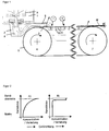
- FIG. 1 are shown in the schematic representation of a horizontal strip casting the principle possible Einwirkstellen for the gas or plasma jets targeted for influencing the material properties of the steel strip.
- a melting vessel 1 is fed from the liquid molten steel 8 via a feed vessel 2 of a runner 3, so that the melt 8 is fed through a pouring nozzle 4 on to a front guide roller 6 and rear guide roller 7 encircling casting belt 5.
- the casting belt 5 is supported between the deflecting rollers 6 and 7 by carrying rollers 9 between which cooling nozzles 10 are arranged for belt cooling.
- the illustrated rotation arrows on the deflection rollers 6 and 7 characterize the conveying direction of the solidifying cast strand 11.
- the melt is still liquid at the top of the strand.
- the melt is inoculated with gas / vapor-shaped metallic and / or non-metallic elements and due to the pressure exerted on the melt by the conveying medium generated flows in the melt controlled mixed.
- the resulting larger surface area and creation of new surfaces results in an increase in the diffusible amount of particles.
- the surface solidification of the cast strand has already begun.
- the porous surface makes it possible for atoms deposited at this point to diffuse from the medium (eg gases or vapors) from the surface into the solid material.
- the admission of the band with gas or plasma jets can take place either at one of the two contact points or at both together both offset in time, and simultaneously.
- the material or later component properties in the band can be set quasi precise location.
Landscapes
- Engineering & Computer Science (AREA)
- Mechanical Engineering (AREA)
- Continuous Casting (AREA)
- Metal Rolling (AREA)
Description
- Die Erfindung betrifft ein Verfahren zum Erzeugen von Warmband mittels Bandgießen mit über den Bandquerschnitt einstellbaren Werkstoffeigenschaften gemäß dem Oberbegriff des Anspruches 1.
- Der stark umkämpfte Automobilmarkt zwingt die Hersteller ständig, nach Lösungen zur Senkung des Flottenverbrauchs unter Beibehaltung eines höchstmöglichen Komforts und Insassenschutzes zu suchen. Dabei spielt einerseits die Gewichtsersparnis aller Fahrzeugkomponenten eine entscheidende Rolle andererseits aber auch ein die passive Sicherheit der Passagiere förderndes Verhalten der einzelnen Bauteile bei hohen statischen und dynamischen Beanspruchungen im Betrieb und im Crashfall.
- Die Vormaterial-Lieferanten versuchen diesen Anforderungen durch die Bereitstellung belastungsoptimierter Bleche oder Bänder aus Stahl (z. B. Taylored welded oder Taylored rolled Blanks) Rechnung zu tragen, die entsprechend den zu erwartenden Belastungen blechdickenoptimiert sind oder aus unterschiedlich festen Werkstoffen bestehen.
- Derartige Bleche oder Bänder aus Stahl müssen vergleichsweise hohen Anforderungen hinsichtlich Festigkeit, Dehnfähigkeit, Zähigkeit, Energieaufnahme und Verarbeitbarkeit beispielsweise durch Kaltumformen, Schweißen und/oder Oberflächenbehandeln, genügen.
- Nachteilig bei der Herstellung belastungsoptimierter Bleche aus Stahl sind bei den geschweißten Blechplatinen die aufwändigen Schneid- und Fügeprozesse sowie scharfe Eigenschaftsgradienten beim Werkstoffübergang.
- Ein Verfahren zum Herstellen eines Verbundbandes aus Stahl ist z. B. aus der
DE 101 24 594 A1 bekannt. Hiernach wird ein nach dem Zweirollenverfahren direkt gegossenes ferritisches Kernband mit einem austenitischen oder hochlegierten ferritischen Plattierungsband plattiert. - Nachteil ist hier der durch die Plattierung bedingte scharfe Sprung der Eigenschaften des Verbundwerkstoffes, der die den jeweiligen Anforderungen entsprechende optimale Anpassung der Eigenschaften über die Banddicke erschwert. Des Weiteren können die Eigenschaften über die Bandbreite nicht variiert werden.
- Ein Verfahren zum Erzeugen von Warmbändern aus Leichtbaustahl mittels einer horizontalen Bandgießanlage ist z. B. aus der Fachzeitschrift steel research 74 (2003), No. 11/12, page 724 - 731, bekannt. Bei diesem Verfahren wird Schmelze aus einem Zulaufgefäß über eine Gießrinne auf ein umlaufendes Gießband einer horizontalen Bandgießanlage aufgegeben. Durch intensive Kühlung des Gießbandes erstarrt die aufgegebene Schmelze zu einem Vorband mit einer Dicke im Bereich zwischen 6 - 20 mm. Nach der Durcherstarrung wird das Vorband einem Warmwalzprozess unterzogen.
- Mit diesem Verfahren lassen sich in idealer Weise z. B. hochmanganhaltige Leichtbaustähle herstellen, die sich über konventionelle Verfahren, wie Stranggießen, nur schwer erzeugen lassen.
- Aus der
JP 58 179542 A DE 34 24 061 A1 offenbart ein Verfahren zur Herstellung einer superabgeschreckten Legierung mit darin dispergierten Sekündärphasen-Teilchen. Die DruckschriftUS 4,523,625 A offenbart wiederum ein Verfahren zur Erzeugung einer amorphen Legierung in der Feststoffpartikel gleichmäßig verteilt eingebracht sind. - Die Druckschrift
DE 199 18 581 A1 offenbart das Gießen von dünnen Bändern aus Kohlenstoffstählen, wobei die Bandfestigkeit dadurch erhöht wird, dass man das Band einer Carburierung- oder Nitrierungs-Behandlung unterwirft. Dies kann direkt nach dem Gießen erfolgen oder nach dem Gießen und anschließenden Kaltwalzen und Glühen. - Bislang ist es mit diesen bekannten Bandgießverfahren jedoch nicht möglich Warmbänder aus Stahl herzustellen, die über den Bandquerschnitt belastungsoptimierte Werkstoffeigenschaften aufweisen.
- Aufgabe der Erfindung ist es, ein Verfahren zum Erzeugen von Verbundwerkstoffen mit einer Stahlmatrix mittels horizontalem Bandgießen anzugeben, mit dem über den Bandquerschnitt die geforderten Werkstoffeigenschaften variabel eingestellt werden können.
- Diese Aufgabe wird ausgehend vom Oberbegriff in Verbindung mit den kennzeichnenden Merkmalen des Anspruches 1 gelöst. Vorteilhafte Weiterbildungen sowie eine Vorrichtung zum Erzeugen von Warmbändern sind Gegenstand von Unteransprüchen.
- Nach der Lehre der Erfindung wirkt auf die noch flüssige und/oder gerade im Erstarrungsbeginn befindliche Stahlschmelze ein aus metallischen und/oder nichtmetallischen, die Werkstoffeigenschaften des Warmbandes beeinflussenden Elementen bestehender Gas- oder Plasmastrahl ein, wobei durch Veränderung der einwirkenden kinetischen Energie des Gas- oderPlasmastrgls, des Gas-Partialdrucks und/oder der anliegenden Temperatur die Konzentration der über den Gas- oder Plasmastrahl in die Schmelze eingebrachten und dort eindiffundierenden Elemente über die Banddicke und Bandbreite eingestellt wird.
- Bei dem beschriebenen Verfahren wird also nicht das Einbringen von Gasbläschen in die Matrix angestrebt, sondern durch das geometrische Eindringen des Gas- oder Plasmastrahls in das noch flüssige oder gerade im Erstarrungsbeginn befindliche Schmelzbad diffundieren die mit dem Gas oder Plasma transportierten Moleküle oder Teilchen in die Matrix ein und beeinflussen so die Werkstoffeigenschaften.
- Das erfindungsgemäße Verfahren ist grundsätzlich für die Erzeugung von Warmbändern aus den verschiedensten metallischen Werkstoffen geeignet, insbesondere auch für hochlegierte Leichtbaustähle.
Das erfindungsgemäße Verfahren bietet erstmals in vorteilhafter Weise die Möglichkeit den spezifischen Anforderungen an die Werkstoffeigenschaften des fertigen Bauteils gezielt Rechnung zu tragen, in dem diese sowohl über die Banddicke wie auch über die Bandbreite gezielt eingestellt werden können.
Hierbei werden gasförmige, dampfförmige oder im Zustand des Plasmas befindliche Legierungsbestandteile mittels dem Zweck entsprechender Abscheidungsverfahren auf die Matrix der noch flüssigen oder gerade in beginnender Erstarrung befindlichen Stahlschmelze aufgebracht, wobei die im Gas bzw. Plasmadampf enthaltenen metallischen und/oder nicht metallischen Elemente in die Matrix eindiffundieren.
Dies können beispielsweise auch Legierungselemente sein, bei denen die Löslichkeit im Eisen bei üblichen Liquidustemperaturen begrenzt ist und die damit über herkömmliche Produktionsverfahren aufgrund von Materialunverträglichkeiten, metallurgischer Entmischung, Abdampfen, etc. gar nicht oder nur begrenzt in die Matrix einbringbar sind. - Außerdem können dem Gasstrahl Feststoffpartikel, wie z. B. Metall- oder Keramikpartikel, zugesetzt werden (Aerosole), so dass mit dem erfindungsgemäßen Verfahren völlig neuartige Verbund- bzw. Gradientenwerkstoffe mit entsprechend neuen Eigenschaften bereitgestellt werden.
- Bei Einsatz eines Gasstrahls kann das Gas z. B. aus N2, CO, CO2, inerten oder reduzierenden Gasen bestehen und je nach Anforderungen kalt oder vorgewärmt auf die Schmelzbadoberfläche auftreffen.
- Durch Einstellung der kinetischen Energie des Gas-Partialdrucks und ggf. der Temperatur diffundieren die Gasmoleküle ausgehend von der Bandoberfläche mit einem auf diese Weise gezielt einstellbaren Gradienten in Banddickenrichtung und beeinflussen entsprechend die Werkstoffeigenschaften des erstarrten Bandes. Bei Verwendung von N2, CO oder CO2 kann beispielsweise über die Banddicke gezielt ein Härtegradient eingestellt werden.
- Bei Einsatz eines heißen Plasmastrahls kann das Plasma z. B. auch aus Metalldämpfen bestehen, womit beliebige Legierungselemente in den Werkstoff eingebracht werden können, um die Werkstoffeigenschaften gezielt zu beeinflussen. Dies kann z. B. Cr sein, um die Korrosionseigenschaften zu verbessern oder Si, um die weichmagnetischen Eigenschaften oder die Zunderbeständigkeit zu verbessern oder Kupfer, um in ausgewählten Materialbereichen den elektrischen Widerstand zu reduzieren.
- Grundsätzlich sind bei der Wahl der nichtmetallischen oder metallischen Elemente keine Grenzen gesetzt, um ein in Bezug auf die geforderten Eigenschaften optimiertes Warmband im Sinne eines Verbund- oder Gradientenwerkstoffes bereitzustellen.
- Vorteilhafterweise erfolgt die Gas- bzw. Plasmastrahlbeaufschlagung über die ganze Breite des Gießbandes bzw. ist variabel einstellbar.
- Hierzu wird mit einer entsprechenden Anzahl an Zuleitungspunkten, z. B. Gasdüsen oder Plasmabrennern, das Gießband über die Breite nur partiell an den geforderten Stellen oder über die gesamte Breite beaufschlagt.
- Vorteilhaft können über eine variable Gas- bzw. Plasmastrahlbeaufschlagung auch die Werkstoffeigenschaften über die Länge des gegossenen Bandes eingestellt werden. Dies kann beispielsweise dadurch erreicht werden, dass während des Bandtransportes im Zuge der Erstarrung die im Regelfall ortsfest angeordnete Gas- bzw. Plasmastrahlbeaufschlagung an- oder abgeschaltet wird, bzw. in ihrer Intensität stufenlos oder gestuft gesteuert wird.
- Die Beaufschlagung des Bandes mit einem Gas- bzw. Plasmastrahl kann dabei nicht nur zum Einbringen von Elementen in den Bandwerkstoff genutzt werden sondern es kann auch vorteilhaft die im Plasmastrahl enthaltene Energie beispielsweise dazu genutzt werden, bereits durch einen Gasstrahl eingebrachte Elemente einer gezielten Wärmebehandlung zu unterziehen um beispielweise eine Diffusionsverstärkung zu erzielen. Somit können mit dem Plasmastrahl z. B. gezielt "Spuren" mit veränderten Werkstoffeigenschaften in das Band eingebracht werden.
- Zusammenfassend ergeben sich aus der Erfindung folgende Vorteile:
- Einstellung benötigter Oberflächeneigenschaften durch teure Legierungselemente nur in der Oberfläche - wirtschaftlicher Materialaufbau durch kostengünstigen Kernwerkstoff
Gezielt beeinflusst werden können:- Verschleiß/Abrieb/Tribologie
- Zunderbeständigkeit
- Korrosionsschutz
- Beschichtbarkeit
- Beklebbarkeit
- elektrische Eigenschaften
- Schweißbarkeit (Widerstandspunktschweißbarkeit)
- thermische Eigenschaften (Bimetall)
- optische Eigenschaften (Aussehen)
- Realisierung von Kombinationen unterschiedlicher Oberflächen- und Materialkerneigenschaften
- Nutzung bereichsweise verschiedener Verfestigungsmechanismen, wie z. B. Mischkristallverfestigung und Ausscheidungen zur Erzeugung von Festigkeitsgradienten bzw. ortsspezifischer verformungs- bzw. Crasheigenschaften.
- In einer Zeichnung wird das erfindungsgemäße Verfahren näher erläutert. Es zeigen:
- Figur 1
- die schematische Darstellung einer horizontalen Bandgießanlage mit Einwirkstellen für die Gas- oder Plasmastrahlen zur Beeinflussung der Werkstoffeigenschaften,
- Figur 2
- einstellbare Konzentrationen bzw. Elementverteilungen über die Blechdicke.
- In
Figur 1 sind in der schematischen Darstellung einer horizontalen Bandgießanlage die prinzipiell möglichen Einwirkstellen für die Gas- oder Plasmastrahlen zur gezielten Beeinflussung der Werkstoffeigenschaften des Stahlbandes dargestellt. - Zu erkennen ist ein Schmelzgefäß 1 aus dem flüssige Stahlschmelze 8 über ein Zulaufgefäß 2 einer Gießrinne 3 zugeführt wird, so dass die Schmelze 8 durch eine Gießdüse 4 auf ein um eine vordere Umlenkrolle 6 und hintere Umlenkrolle 7 umlaufendes Gießband 5 aufgegeben wird. Abgestützt wird das Gießband 5 zwischen den Umlenkrollen 6 und 7 von Tragrollen 9 zwischen denen zur Bandkühlung Kühldüsen 10 angeordnet sind. Die dargestellten Rotationspfeile an den Umlenkrollen 6 und 7 kennzeichnen die Förderrichtung des erstarrenden Gießstrangs 11.
- Die möglichen Einwirkstellen des Gas- oder Plasmastrahls auf den Gießstrang sind mit I und II gekennzeichnet.
- Bei der Einwirkstelle I ist die Schmelze auch an der Strangoberseite noch flüssig. Durch das Eindringen des Fördermediums (z. B. mittels eines Gas- oder Plasmastrahls) in das noch flüssige Schmelzbad wird die Schmelze mit gas-/dampf-förmigen metallischen und/oder nichtmetallischen Elementen geimpft und infolge der auf die Schmelze durch das Fördermedium ausgeübten Druck erzeugten Strömungen in der Schmelze gesteuert durchmischt. Die damit erreichte größere Oberfläche und Schaffung von neuen Oberflächen hat eine Steigerung der eindiffundierbaren Teilchenmenge zur Folge.
- Mittels eines in Gießrichtung folgenden elektromagnetischen Querrührers kann eine weitere Durchmischung durch Verteilung der bereits eindiffundierten Teilchen bzw. die Erhöhung der eindiffundierten Menge durch die Schaffung neuer Oberflächen erreicht werden.
- Im Bereich der Einwirkstelle II hat die Oberseitenerstarrung des Gießstranges bereits eingesetzt. Die porös gehaltene Oberfläche ermöglicht, dass an dieser Stelle aus dem Fördermedium (z. B. Gase oder Dämpfe) abgeschiedene Atome von der Oberfläche in das feste Material diffundieren können.
- Die Beaufschlagung des Bandes mit Gas- oder Plasmastrahlen kann dabei entweder an einer der beiden Einwirkstellen erfolgen oder an beiden gemeinsam sowohl zeitlich versetzt, als auch gleichzeitig.
- Mit einer zusätzlichen variablen Beaufschlagung über Bandbreite und -länge lassen sich die vielfältigsten Anforderungen hinsichtlich der geforderten Werkstoffeigenschaften erzielen. Somit können die Werkstoff- bzw. späteren Bauteileigenschaften im Band quasi ortsgenau eingestellt werden.
- Mit den beschriebenen Aufgabepositionen lassen sich die in
Figur 2 dargestellten Konzentrationen bzw. Verteilungen über der Banddicke einstellen: - Aufgabeposition I → Verteilung A): Gradientenwerkstoffe mit stetigem einseitigem Oberflächengradient. Dieser sich aus der Diffusion ergebende Gradient kann durch die kinetische Energie des Gas- bzw. Plasmastrahls, den Gas-Partialdruck sowie die anliegende Temperatur (Diffusionsgeschwindigkeit ist temperaturabhängig) eingestellt werden.
- Aufgabeposition II → Verseilung B): Verbundwerkstoffe mit einseitiger sprunghafter Verteilungsänderung außen.
-
Nr. Bezeichnung 1 Schmelzgefäß 2 Zulaufgefäß 3 Gießrinne 4 Gießdüse 5 Gießband 6 vordere Umlenkrolle 7 hintere Umlenkrolle 8 Schmelze 9 Tragrollen 10 Kühldüsen 11 Gießstrang I - II Aufgabepositionen
Claims (8)
- Verfahren zum Erzeugen von Warmband aus Stahl mit über den Bandquerschnitt einstellbaren Werkstoffeigenschaften, wobei eine Stahlschmelze mittels einer Gießrinne auf ein umlaufendes Gießband einer horizontalen Bandgießanlage aufgegeben wird, die zu einem Vorband mit einer Dicke zwischen 6 bis 20 mm erstarrt und das Vorband nach der Durcherstarrung einem Warmwalzprozess unterzogen wird
dadurch gekennzeichnet,
dass auf die noch flüssige und/oder gerade im Erstarrungsbeginn befindliche Stahlschmelze ein aus metallischen und/oder nichtmetallischen die Werkstoffeigenschaften des Warmbandes beeinflussenden Elementen bestehender Gas- oder Plasmastrahl einwirkt und durch Veränderung der einwirkenden kinetischen Energie des Gas- oder Plasmastrahls, des Gas-Partialdrucks und/oder der anliegenden Temperatur die Konzentration der über den Gas- oder Plasmastrahl in die Schmelze eingebrachten und dort eindiffundierenden Elemente über die Banddicke und Bandbreite eingestellt wird. - Verfahren nach Anspruch 1
dadurch gekennzeichnet,
dass dem Gas- oder Plasmastrahl Feststoffpartikel zugesetzt sind. - Verfahren nach Anspruch 1 und 2
dadurch gekennzeichnet,
dass das für den Gasstrahl verwendete Gas inert und/oder reduzierend ist. - Verfahren nach Anspruch 1 und 2
dadurch gekennzeichnet,
dass das für den Gasstrahl verwendete Gas ein Mischgas aus einem inerten Gas als Träger und einem reduzierenden Gas ist. - Verfahren nach einem der Ansprüche 1 bis 4
dadurch gekennzeichnet,
dass das Gas kalt oder vorgewärmt ist. - Verfahren nach einem der Ansprüche 1 bis 5
dadurch gekennzeichnet,
dass die Werkstoffeigenschaften symmetrisch oder asymmetrisch über die Breite des Bandes eingestellt werden. - Verfahren nach einem der Ansprüche 1 bis 6
dadurch gekennzeichnet,
dass die Werkstoffeigenschaften zusätzlich über die gegossene Länge des Bandes variabel eingestellt werden. - Verfahren nach einem der Ansprüche 1 bis 7
dadurch gekennzeichnet,
dass durch gezielte Beaufschlagung der noch flüssigen Gießbandrandbereiche mit dem Gas- oder Plasmastrahl die Form der Gießbandkanten im Zuge der Erstarrung beeinflusst werden.
Applications Claiming Priority (2)
| Application Number | Priority Date | Filing Date | Title |
|---|---|---|---|
| DE102009038974A DE102009038974B3 (de) | 2009-08-21 | 2009-08-21 | Verfahren zum Erzeugen von Warmband mittels Bandgießen mit über den Bandquerschnitt einstellbaren Werkstoffeigenschaften |
| PCT/DE2010/000826 WO2011020451A1 (de) | 2009-08-21 | 2010-07-14 | Verfahren zum erzeugen von warmband mittels bandgiessen mit über den bandquerschnitt einstellbaren werkstoffeigenschaften |
Publications (2)
| Publication Number | Publication Date |
|---|---|
| EP2467221A1 EP2467221A1 (de) | 2012-06-27 |
| EP2467221B1 true EP2467221B1 (de) | 2016-01-27 |
Family
ID=42993819
Family Applications (1)
| Application Number | Title | Priority Date | Filing Date |
|---|---|---|---|
| EP10749463.5A Not-in-force EP2467221B1 (de) | 2009-08-21 | 2010-07-14 | Verfahren zum erzeugen von warmband mittels bandgiessen mit über den bandquerschnitt einstellbaren werkstoffeigenschaften |
Country Status (6)
| Country | Link |
|---|---|
| US (1) | US10086426B2 (de) |
| EP (1) | EP2467221B1 (de) |
| KR (1) | KR20120051028A (de) |
| DE (1) | DE102009038974B3 (de) |
| RU (1) | RU2537580C2 (de) |
| WO (1) | WO2011020451A1 (de) |
Families Citing this family (3)
| Publication number | Priority date | Publication date | Assignee | Title |
|---|---|---|---|---|
| DE102012002079B4 (de) | 2012-01-30 | 2015-05-13 | Salzgitter Flachstahl Gmbh | Verfahren zur Herstellung eines kalt- oder warmgewalzten Stahlbandes aus einem höchstfesten Mehrphasenstahl |
| DE102012013425A1 (de) | 2012-07-03 | 2014-01-09 | Salzgitter Flachstahl Gmbh | Kontinuierlich arbeitende Bandgieß- und Walzanlage |
| WO2021001495A1 (de) * | 2019-07-03 | 2021-01-07 | Hydro Aluminium Rolled Products Gmbh | Schmelzezuführung für bandgussanlagen |
Family Cites Families (14)
| Publication number | Priority date | Publication date | Assignee | Title |
|---|---|---|---|---|
| US4224356A (en) * | 1977-05-31 | 1980-09-23 | The Secretary For Defence In Her Britannic Majesty's Government Of The United Kingdom Of Great Britain And Northern Ireland | Deposition of metals on a base |
| JPS58179542A (ja) | 1982-04-12 | 1983-10-20 | Daido Steel Co Ltd | 粒子分散金属の製造方法 |
| US4523625A (en) * | 1983-02-07 | 1985-06-18 | Cornell Research Foundation, Inc. | Method of making strips of metallic glasses having uniformly distributed embedded particulate matter |
| JPS6017029A (ja) | 1983-07-09 | 1985-01-28 | Alps Electric Co Ltd | 第2相粒子分散型超急冷合金の製造方法 |
| US4588021A (en) * | 1983-11-07 | 1986-05-13 | Hazelett Strip-Casting Corporation | Matrix coatings on endless flexible metallic belts for continuous casting machines method of forming such coatings and the coated belts |
| JPH01306052A (ja) * | 1988-06-02 | 1989-12-11 | Sumitomo Metal Ind Ltd | 連続鋳造用ベルト |
| US6110296A (en) | 1998-04-28 | 2000-08-29 | Usx Corporation | Thin strip casting of carbon steels |
| EP2233605B1 (de) * | 2000-12-12 | 2012-09-26 | Konica Corporation | Optischer Überzug, enthaltend eine Antreflexionsschicht |
| DE10124594B4 (de) * | 2001-05-21 | 2006-10-12 | Thyssenkrupp Steel Ag | Verfahren zum Herstellen eines Verbundbandes aus Stahl durch Walzplattieren eines direkt gegossenen Stahlbandes sowie Verwendung eines solchen Verbundbandes |
| RU2233346C1 (ru) * | 2003-04-22 | 2004-07-27 | Открытое акционерное общество "Всероссийский институт легких сплавов" | Алюминиевый сплав для получения пеноалюминия и способ получения пеноалюминия из него |
| DE102004053620A1 (de) | 2004-11-03 | 2006-05-04 | Salzgitter Flachstahl Gmbh | Hochfester, lufthärtender Stahl mit ausgezeichneten Umformeigenschaften |
| DE102004062636B4 (de) * | 2004-12-21 | 2007-05-24 | Salzgitter Flachstahl Gmbh | Einrichtung zum horizontalen Bandgießen von Stahl |
| DE102005062854A1 (de) | 2005-12-23 | 2007-07-05 | Salzgitter Flachstahl Gmbh | Verfahren und Einrichtung zum Erzeugen von metallischen Warmbändern insbesondere aus Leichtbaustahl |
| DE102007058222A1 (de) | 2007-12-03 | 2009-06-04 | Salzgitter Flachstahl Gmbh | Stahl für hochfeste Bauteile aus Bändern, Blechen oder Rohren mit ausgezeichneter Umformbarkeit und besonderer Eignung für Hochtemperatur-Beschichtungsverfahren |
-
2009
- 2009-08-21 DE DE102009038974A patent/DE102009038974B3/de not_active Expired - Fee Related
-
2010
- 2010-07-14 RU RU2012110590/02A patent/RU2537580C2/ru not_active IP Right Cessation
- 2010-07-14 US US13/391,166 patent/US10086426B2/en not_active Expired - Fee Related
- 2010-07-14 KR KR1020127004595A patent/KR20120051028A/ko not_active Ceased
- 2010-07-14 WO PCT/DE2010/000826 patent/WO2011020451A1/de not_active Ceased
- 2010-07-14 EP EP10749463.5A patent/EP2467221B1/de not_active Not-in-force
Also Published As
| Publication number | Publication date |
|---|---|
| EP2467221A1 (de) | 2012-06-27 |
| WO2011020451A1 (de) | 2011-02-24 |
| DE102009038974B3 (de) | 2010-11-25 |
| KR20120051028A (ko) | 2012-05-21 |
| RU2012110590A (ru) | 2013-09-27 |
| US20120279677A1 (en) | 2012-11-08 |
| RU2537580C2 (ru) | 2015-01-10 |
| US10086426B2 (en) | 2018-10-02 |
Similar Documents
| Publication | Publication Date | Title |
|---|---|---|
| EP2547800B1 (de) | Verfahren zur herstellung von werkstücken aus leichtbaustahl mit über die wanddicke einstellbaren werkstoffeigenschaften | |
| EP1752548B1 (de) | Verfahren zur Herstellung von kornorientiertem Elektroband | |
| EP1326723B9 (de) | Ein stahlherstellungsverfahren | |
| EP2759614B1 (de) | Verfahren zum Erzeugen eines Stahlflachprodukts mit einem amorphen, teilamorphen oder feinkristallinen Gefüge und derart beschaffenes Stahlflachprodukt | |
| EP1752549A1 (de) | Verfahren zur Herstellung von kornorietiertem Elektroband | |
| DE102009036378A1 (de) | Verfahren und Vorrichtung zum Herstellen eines mikrolegierten Stahls, insbesondere eines Röhrenstahls | |
| WO2002024969A1 (de) | Verfahren zum herstellen eines überwiegend aus mn-austenit bestehenden stahlbands oder -blechs | |
| DE112015005690T5 (de) | Warmgewalztes martensitisches Leichtbau-Stahlblech und Verfahren zum Herstellen desselben | |
| DE102009018683A1 (de) | Verfahren und Vorrichtung zum Stranggießen einer Bramme | |
| EP2467221B1 (de) | Verfahren zum erzeugen von warmband mittels bandgiessen mit über den bandquerschnitt einstellbaren werkstoffeigenschaften | |
| EP2406023A1 (de) | Verfahren zum erzeugen eines warmbandes und aus einem triplex-leichtbaustahl hergestelltes warmband | |
| EP1404484B1 (de) | Bandförmige schneidwerkzeuge | |
| EP1109638B1 (de) | Verfahren zur herstellung belastungsoptimierter stahlbänder | |
| EP2483014B1 (de) | Verfahren zum bandgiessen von stahl und anlage zum bandgiessen | |
| DE102011010040B3 (de) | Verfahren und Einrichtung zum Erzeugen eines gegossenen Bandes aus Stahl mit über den Bandquerschnitt und die Bandlänge einstellbaren Werkstoffeigenschaften | |
| DE102014005662A1 (de) | Werkstoffkonzept für einen umformbaren Leichtbaustahl | |
| EP1702993B1 (de) | Verfahren und Vorrichtung zum abschnittsweisen Durchhärten von aus Stahlblech fertig geformten Bauteilen | |
| EP2445663B1 (de) | Verfahren und vorrichtung zum erzeugen von stahlbändern mittels bandgiessen | |
| EP2511039A1 (de) | Verfahren zum Laserstrahlschweissen eines mit einem metallischen Überzug versehenen Vorproduktes aus Stahl unter Verwendung eines Schutzgases aus Ar, Co2 und O2 | |
| DE102010026245B4 (de) | Verfahren zum Erzeugen von Warmband mittels Bandgießen mit über den Bandquerschnitt und die Bandlänge einstellbaren Werkstoffeigenschaften | |
| DE2146227A1 (de) | Verfahren zur Erzeugung von dreischichtigen Walzprodukten | |
| DE10138794A1 (de) | Verfahren und Anlage zur Produktion von Flach- und Langprodukten | |
| DE10107027A1 (de) | Verfahren zum Herstellen von metallischen Bändern mit Abschnitten unterschiedlicher Materialeigenschaften | |
| DE102015116517A1 (de) | Vorrichtung und Verfahren zur kontinuierlichen Herstellung eines bandförmigen, metallischen Werkstücks |
Legal Events
| Date | Code | Title | Description |
|---|---|---|---|
| PUAI | Public reference made under article 153(3) epc to a published international application that has entered the european phase |
Free format text: ORIGINAL CODE: 0009012 |
|
| 17P | Request for examination filed |
Effective date: 20111216 |
|
| AK | Designated contracting states |
Kind code of ref document: A1 Designated state(s): AL AT BE BG CH CY CZ DE DK EE ES FI FR GB GR HR HU IE IS IT LI LT LU LV MC MK MT NL NO PL PT RO SE SI SK SM TR |
|
| RIN1 | Information on inventor provided before grant (corrected) |
Inventor name: SCHMIDT-JUERGENSEN, RUNE Inventor name: FLAXA, VOLKER Inventor name: SPITZER, KARL-HEINZ Inventor name: KROOS, JOACHIM Inventor name: SCHAEPERKOETTER, MARKUS Inventor name: EICHHOLZ, HELLFRIED |
|
| DAX | Request for extension of the european patent (deleted) | ||
| GRAP | Despatch of communication of intention to grant a patent |
Free format text: ORIGINAL CODE: EPIDOSNIGR1 |
|
| INTG | Intention to grant announced |
Effective date: 20150807 |
|
| GRAS | Grant fee paid |
Free format text: ORIGINAL CODE: EPIDOSNIGR3 |
|
| GRAA | (expected) grant |
Free format text: ORIGINAL CODE: 0009210 |
|
| AK | Designated contracting states |
Kind code of ref document: B1 Designated state(s): AL AT BE BG CH CY CZ DE DK EE ES FI FR GB GR HR HU IE IS IT LI LT LU LV MC MK MT NL NO PL PT RO SE SI SK SM TR |
|
| REG | Reference to a national code |
Ref country code: GB Ref legal event code: FG4D Free format text: NOT ENGLISH |
|
| REG | Reference to a national code |
Ref country code: CH Ref legal event code: EP |
|
| REG | Reference to a national code |
Ref country code: AT Ref legal event code: REF Ref document number: 772457 Country of ref document: AT Kind code of ref document: T Effective date: 20160215 |
|
| REG | Reference to a national code |
Ref country code: IE Ref legal event code: FG4D Free format text: LANGUAGE OF EP DOCUMENT: GERMAN |
|
| REG | Reference to a national code |
Ref country code: DE Ref legal event code: R096 Ref document number: 502010010997 Country of ref document: DE |
|
| REG | Reference to a national code |
Ref country code: NL Ref legal event code: FP |
|
| REG | Reference to a national code |
Ref country code: LT Ref legal event code: MG4D |
|
| REG | Reference to a national code |
Ref country code: FR Ref legal event code: PLFP Year of fee payment: 7 |
|
| PG25 | Lapsed in a contracting state [announced via postgrant information from national office to epo] |
Ref country code: IT Free format text: LAPSE BECAUSE OF FAILURE TO SUBMIT A TRANSLATION OF THE DESCRIPTION OR TO PAY THE FEE WITHIN THE PRESCRIBED TIME-LIMIT Effective date: 20160127 Ref country code: FI Free format text: LAPSE BECAUSE OF FAILURE TO SUBMIT A TRANSLATION OF THE DESCRIPTION OR TO PAY THE FEE WITHIN THE PRESCRIBED TIME-LIMIT Effective date: 20160127 Ref country code: NO Free format text: LAPSE BECAUSE OF FAILURE TO SUBMIT A TRANSLATION OF THE DESCRIPTION OR TO PAY THE FEE WITHIN THE PRESCRIBED TIME-LIMIT Effective date: 20160427 Ref country code: GR Free format text: LAPSE BECAUSE OF FAILURE TO SUBMIT A TRANSLATION OF THE DESCRIPTION OR TO PAY THE FEE WITHIN THE PRESCRIBED TIME-LIMIT Effective date: 20160428 Ref country code: ES Free format text: LAPSE BECAUSE OF FAILURE TO SUBMIT A TRANSLATION OF THE DESCRIPTION OR TO PAY THE FEE WITHIN THE PRESCRIBED TIME-LIMIT Effective date: 20160127 Ref country code: HR Free format text: LAPSE BECAUSE OF FAILURE TO SUBMIT A TRANSLATION OF THE DESCRIPTION OR TO PAY THE FEE WITHIN THE PRESCRIBED TIME-LIMIT Effective date: 20160127 |
|
| PG25 | Lapsed in a contracting state [announced via postgrant information from national office to epo] |
Ref country code: SE Free format text: LAPSE BECAUSE OF FAILURE TO SUBMIT A TRANSLATION OF THE DESCRIPTION OR TO PAY THE FEE WITHIN THE PRESCRIBED TIME-LIMIT Effective date: 20160127 Ref country code: LV Free format text: LAPSE BECAUSE OF FAILURE TO SUBMIT A TRANSLATION OF THE DESCRIPTION OR TO PAY THE FEE WITHIN THE PRESCRIBED TIME-LIMIT Effective date: 20160127 Ref country code: PL Free format text: LAPSE BECAUSE OF FAILURE TO SUBMIT A TRANSLATION OF THE DESCRIPTION OR TO PAY THE FEE WITHIN THE PRESCRIBED TIME-LIMIT Effective date: 20160127 Ref country code: PT Free format text: LAPSE BECAUSE OF FAILURE TO SUBMIT A TRANSLATION OF THE DESCRIPTION OR TO PAY THE FEE WITHIN THE PRESCRIBED TIME-LIMIT Effective date: 20160527 Ref country code: LT Free format text: LAPSE BECAUSE OF FAILURE TO SUBMIT A TRANSLATION OF THE DESCRIPTION OR TO PAY THE FEE WITHIN THE PRESCRIBED TIME-LIMIT Effective date: 20160127 Ref country code: IS Free format text: LAPSE BECAUSE OF FAILURE TO SUBMIT A TRANSLATION OF THE DESCRIPTION OR TO PAY THE FEE WITHIN THE PRESCRIBED TIME-LIMIT Effective date: 20160527 |
|
| PGFP | Annual fee paid to national office [announced via postgrant information from national office to epo] |
Ref country code: NL Payment date: 20160720 Year of fee payment: 7 |
|
| REG | Reference to a national code |
Ref country code: DE Ref legal event code: R097 Ref document number: 502010010997 Country of ref document: DE |
|
| PG25 | Lapsed in a contracting state [announced via postgrant information from national office to epo] |
Ref country code: DK Free format text: LAPSE BECAUSE OF FAILURE TO SUBMIT A TRANSLATION OF THE DESCRIPTION OR TO PAY THE FEE WITHIN THE PRESCRIBED TIME-LIMIT Effective date: 20160127 Ref country code: EE Free format text: LAPSE BECAUSE OF FAILURE TO SUBMIT A TRANSLATION OF THE DESCRIPTION OR TO PAY THE FEE WITHIN THE PRESCRIBED TIME-LIMIT Effective date: 20160127 |
|
| PG25 | Lapsed in a contracting state [announced via postgrant information from national office to epo] |
Ref country code: SK Free format text: LAPSE BECAUSE OF FAILURE TO SUBMIT A TRANSLATION OF THE DESCRIPTION OR TO PAY THE FEE WITHIN THE PRESCRIBED TIME-LIMIT Effective date: 20160127 Ref country code: CZ Free format text: LAPSE BECAUSE OF FAILURE TO SUBMIT A TRANSLATION OF THE DESCRIPTION OR TO PAY THE FEE WITHIN THE PRESCRIBED TIME-LIMIT Effective date: 20160127 Ref country code: RO Free format text: LAPSE BECAUSE OF FAILURE TO SUBMIT A TRANSLATION OF THE DESCRIPTION OR TO PAY THE FEE WITHIN THE PRESCRIBED TIME-LIMIT Effective date: 20160127 Ref country code: SM Free format text: LAPSE BECAUSE OF FAILURE TO SUBMIT A TRANSLATION OF THE DESCRIPTION OR TO PAY THE FEE WITHIN THE PRESCRIBED TIME-LIMIT Effective date: 20160127 |
|
| PGFP | Annual fee paid to national office [announced via postgrant information from national office to epo] |
Ref country code: AT Payment date: 20160721 Year of fee payment: 7 |
|
| PLBE | No opposition filed within time limit |
Free format text: ORIGINAL CODE: 0009261 |
|
| STAA | Information on the status of an ep patent application or granted ep patent |
Free format text: STATUS: NO OPPOSITION FILED WITHIN TIME LIMIT |
|
| 26N | No opposition filed |
Effective date: 20161028 |
|
| PG25 | Lapsed in a contracting state [announced via postgrant information from national office to epo] |
Ref country code: BG Free format text: LAPSE BECAUSE OF FAILURE TO SUBMIT A TRANSLATION OF THE DESCRIPTION OR TO PAY THE FEE WITHIN THE PRESCRIBED TIME-LIMIT Effective date: 20160427 Ref country code: SI Free format text: LAPSE BECAUSE OF FAILURE TO SUBMIT A TRANSLATION OF THE DESCRIPTION OR TO PAY THE FEE WITHIN THE PRESCRIBED TIME-LIMIT Effective date: 20160127 |
|
| REG | Reference to a national code |
Ref country code: CH Ref legal event code: PL |
|
| GBPC | Gb: european patent ceased through non-payment of renewal fee |
Effective date: 20160714 |
|
| PG25 | Lapsed in a contracting state [announced via postgrant information from national office to epo] |
Ref country code: MC Free format text: LAPSE BECAUSE OF FAILURE TO SUBMIT A TRANSLATION OF THE DESCRIPTION OR TO PAY THE FEE WITHIN THE PRESCRIBED TIME-LIMIT Effective date: 20160127 |
|
| PG25 | Lapsed in a contracting state [announced via postgrant information from national office to epo] |
Ref country code: LI Free format text: LAPSE BECAUSE OF NON-PAYMENT OF DUE FEES Effective date: 20160731 Ref country code: CH Free format text: LAPSE BECAUSE OF NON-PAYMENT OF DUE FEES Effective date: 20160731 |
|
| REG | Reference to a national code |
Ref country code: IE Ref legal event code: MM4A |
|
| PG25 | Lapsed in a contracting state [announced via postgrant information from national office to epo] |
Ref country code: GB Free format text: LAPSE BECAUSE OF NON-PAYMENT OF DUE FEES Effective date: 20160714 |
|
| REG | Reference to a national code |
Ref country code: FR Ref legal event code: PLFP Year of fee payment: 8 |
|
| PG25 | Lapsed in a contracting state [announced via postgrant information from national office to epo] |
Ref country code: IE Free format text: LAPSE BECAUSE OF NON-PAYMENT OF DUE FEES Effective date: 20160714 |
|
| PG25 | Lapsed in a contracting state [announced via postgrant information from national office to epo] |
Ref country code: LU Free format text: LAPSE BECAUSE OF NON-PAYMENT OF DUE FEES Effective date: 20160714 |
|
| REG | Reference to a national code |
Ref country code: NL Ref legal event code: MM Effective date: 20170801 |
|
| REG | Reference to a national code |
Ref country code: AT Ref legal event code: MM01 Ref document number: 772457 Country of ref document: AT Kind code of ref document: T Effective date: 20170714 |
|
| PG25 | Lapsed in a contracting state [announced via postgrant information from national office to epo] |
Ref country code: NL Free format text: LAPSE BECAUSE OF NON-PAYMENT OF DUE FEES Effective date: 20170801 |
|
| PG25 | Lapsed in a contracting state [announced via postgrant information from national office to epo] |
Ref country code: AT Free format text: LAPSE BECAUSE OF NON-PAYMENT OF DUE FEES Effective date: 20170714 Ref country code: CY Free format text: LAPSE BECAUSE OF FAILURE TO SUBMIT A TRANSLATION OF THE DESCRIPTION OR TO PAY THE FEE WITHIN THE PRESCRIBED TIME-LIMIT Effective date: 20160127 Ref country code: HU Free format text: LAPSE BECAUSE OF FAILURE TO SUBMIT A TRANSLATION OF THE DESCRIPTION OR TO PAY THE FEE WITHIN THE PRESCRIBED TIME-LIMIT; INVALID AB INITIO Effective date: 20100714 |
|
| PG25 | Lapsed in a contracting state [announced via postgrant information from national office to epo] |
Ref country code: MK Free format text: LAPSE BECAUSE OF FAILURE TO SUBMIT A TRANSLATION OF THE DESCRIPTION OR TO PAY THE FEE WITHIN THE PRESCRIBED TIME-LIMIT Effective date: 20160127 Ref country code: MT Free format text: LAPSE BECAUSE OF FAILURE TO SUBMIT A TRANSLATION OF THE DESCRIPTION OR TO PAY THE FEE WITHIN THE PRESCRIBED TIME-LIMIT Effective date: 20160127 |
|
| REG | Reference to a national code |
Ref country code: FR Ref legal event code: PLFP Year of fee payment: 9 |
|
| PG25 | Lapsed in a contracting state [announced via postgrant information from national office to epo] |
Ref country code: AL Free format text: LAPSE BECAUSE OF FAILURE TO SUBMIT A TRANSLATION OF THE DESCRIPTION OR TO PAY THE FEE WITHIN THE PRESCRIBED TIME-LIMIT Effective date: 20160127 |
|
| PGFP | Annual fee paid to national office [announced via postgrant information from national office to epo] |
Ref country code: FR Payment date: 20180725 Year of fee payment: 9 |
|
| PGFP | Annual fee paid to national office [announced via postgrant information from national office to epo] |
Ref country code: BE Payment date: 20180718 Year of fee payment: 9 Ref country code: TR Payment date: 20180712 Year of fee payment: 9 |
|
| REG | Reference to a national code |
Ref country code: BE Ref legal event code: MM Effective date: 20190731 |
|
| PG25 | Lapsed in a contracting state [announced via postgrant information from national office to epo] |
Ref country code: BE Free format text: LAPSE BECAUSE OF NON-PAYMENT OF DUE FEES Effective date: 20190731 |
|
| PG25 | Lapsed in a contracting state [announced via postgrant information from national office to epo] |
Ref country code: FR Free format text: LAPSE BECAUSE OF NON-PAYMENT OF DUE FEES Effective date: 20190731 |
|
| PG25 | Lapsed in a contracting state [announced via postgrant information from national office to epo] |
Ref country code: TR Free format text: LAPSE BECAUSE OF NON-PAYMENT OF DUE FEES Effective date: 20190714 |
|
| PGFP | Annual fee paid to national office [announced via postgrant information from national office to epo] |
Ref country code: DE Payment date: 20220720 Year of fee payment: 13 |
|
| REG | Reference to a national code |
Ref country code: DE Ref legal event code: R119 Ref document number: 502010010997 Country of ref document: DE |
|
| PG25 | Lapsed in a contracting state [announced via postgrant information from national office to epo] |
Ref country code: DE Free format text: LAPSE BECAUSE OF NON-PAYMENT OF DUE FEES Effective date: 20240201 |