EP2466105A1 - Vorrichtung zum Erstellen einer elektrischen Verbindung - Google Patents
Vorrichtung zum Erstellen einer elektrischen Verbindung Download PDFInfo
- Publication number
- EP2466105A1 EP2466105A1 EP20110192604 EP11192604A EP2466105A1 EP 2466105 A1 EP2466105 A1 EP 2466105A1 EP 20110192604 EP20110192604 EP 20110192604 EP 11192604 A EP11192604 A EP 11192604A EP 2466105 A1 EP2466105 A1 EP 2466105A1
- Authority
- EP
- European Patent Office
- Prior art keywords
- holding part
- electrical component
- electrical
- connector
- connection
- Prior art date
- Legal status (The legal status is an assumption and is not a legal conclusion. Google has not performed a legal analysis and makes no representation as to the accuracy of the status listed.)
- Granted
Links
Images


Classifications
-
- F—MECHANICAL ENGINEERING; LIGHTING; HEATING; WEAPONS; BLASTING
- F02—COMBUSTION ENGINES; HOT-GAS OR COMBUSTION-PRODUCT ENGINE PLANTS
- F02M—SUPPLYING COMBUSTION ENGINES IN GENERAL WITH COMBUSTIBLE MIXTURES OR CONSTITUENTS THEREOF
- F02M37/00—Apparatus or systems for feeding liquid fuel from storage containers to carburettors or fuel-injection apparatus; Arrangements for purifying liquid fuel specially adapted for, or arranged on, internal-combustion engines
- F02M37/04—Feeding by means of driven pumps
- F02M37/08—Feeding by means of driven pumps electrically driven
- F02M37/10—Feeding by means of driven pumps electrically driven submerged in fuel, e.g. in reservoir
- F02M37/103—Mounting pumps on fuel tanks
-
- B—PERFORMING OPERATIONS; TRANSPORTING
- B60—VEHICLES IN GENERAL
- B60K—ARRANGEMENT OR MOUNTING OF PROPULSION UNITS OR OF TRANSMISSIONS IN VEHICLES; ARRANGEMENT OR MOUNTING OF PLURAL DIVERSE PRIME-MOVERS IN VEHICLES; AUXILIARY DRIVES FOR VEHICLES; INSTRUMENTATION OR DASHBOARDS FOR VEHICLES; ARRANGEMENTS IN CONNECTION WITH COOLING, AIR INTAKE, GAS EXHAUST OR FUEL SUPPLY OF PROPULSION UNITS IN VEHICLES
- B60K15/00—Arrangement in connection with fuel supply of combustion engines or other fuel consuming energy converters, e.g. fuel cells; Mounting or construction of fuel tanks
- B60K15/03—Fuel tanks
-
- G—PHYSICS
- G01—MEASURING; TESTING
- G01F—MEASURING VOLUME, VOLUME FLOW, MASS FLOW OR LIQUID LEVEL; METERING BY VOLUME
- G01F23/00—Indicating or measuring liquid level or level of fluent solid material, e.g. indicating in terms of volume or indicating by means of an alarm
- G01F23/30—Indicating or measuring liquid level or level of fluent solid material, e.g. indicating in terms of volume or indicating by means of an alarm by floats
- G01F23/32—Indicating or measuring liquid level or level of fluent solid material, e.g. indicating in terms of volume or indicating by means of an alarm by floats using rotatable arms or other pivotable transmission elements
- G01F23/36—Indicating or measuring liquid level or level of fluent solid material, e.g. indicating in terms of volume or indicating by means of an alarm by floats using rotatable arms or other pivotable transmission elements using electrically actuated indicating means
-
- H—ELECTRICITY
- H01—ELECTRIC ELEMENTS
- H01R—ELECTRICALLY-CONDUCTIVE CONNECTIONS; STRUCTURAL ASSOCIATIONS OF A PLURALITY OF MUTUALLY-INSULATED ELECTRICAL CONNECTING ELEMENTS; COUPLING DEVICES; CURRENT COLLECTORS
- H01R24/00—Two-part coupling devices, or either of their cooperating parts, characterised by their overall structure
- H01R24/66—Two-part coupling devices, or either of their cooperating parts, characterised by their overall structure with pins, blades or analogous contacts and secured to apparatus or structure, e.g. to a wall
- H01R24/68—Two-part coupling devices, or either of their cooperating parts, characterised by their overall structure with pins, blades or analogous contacts and secured to apparatus or structure, e.g. to a wall mounted on directly pluggable apparatus
-
- B—PERFORMING OPERATIONS; TRANSPORTING
- B60—VEHICLES IN GENERAL
- B60K—ARRANGEMENT OR MOUNTING OF PROPULSION UNITS OR OF TRANSMISSIONS IN VEHICLES; ARRANGEMENT OR MOUNTING OF PLURAL DIVERSE PRIME-MOVERS IN VEHICLES; AUXILIARY DRIVES FOR VEHICLES; INSTRUMENTATION OR DASHBOARDS FOR VEHICLES; ARRANGEMENTS IN CONNECTION WITH COOLING, AIR INTAKE, GAS EXHAUST OR FUEL SUPPLY OF PROPULSION UNITS IN VEHICLES
- B60K15/00—Arrangement in connection with fuel supply of combustion engines or other fuel consuming energy converters, e.g. fuel cells; Mounting or construction of fuel tanks
- B60K15/03—Fuel tanks
- B60K2015/0321—Fuel tanks characterised by special sensors, the mounting thereof
- B60K2015/03217—Fuel level sensors
-
- F—MECHANICAL ENGINEERING; LIGHTING; HEATING; WEAPONS; BLASTING
- F02—COMBUSTION ENGINES; HOT-GAS OR COMBUSTION-PRODUCT ENGINE PLANTS
- F02M—SUPPLYING COMBUSTION ENGINES IN GENERAL WITH COMBUSTIBLE MIXTURES OR CONSTITUENTS THEREOF
- F02M37/00—Apparatus or systems for feeding liquid fuel from storage containers to carburettors or fuel-injection apparatus; Arrangements for purifying liquid fuel specially adapted for, or arranged on, internal-combustion engines
- F02M37/04—Feeding by means of driven pumps
- F02M37/08—Feeding by means of driven pumps electrically driven
- F02M2037/082—Details of the entry of the current supply lines into the pump housing, e.g. wire connectors, grommets, plugs or sockets
-
- H—ELECTRICITY
- H01—ELECTRIC ELEMENTS
- H01R—ELECTRICALLY-CONDUCTIVE CONNECTIONS; STRUCTURAL ASSOCIATIONS OF A PLURALITY OF MUTUALLY-INSULATED ELECTRICAL CONNECTING ELEMENTS; COUPLING DEVICES; CURRENT COLLECTORS
- H01R13/00—Details of coupling devices of the kinds covered by groups H01R12/70 or H01R24/00 - H01R33/00
- H01R13/62—Means for facilitating engagement or disengagement of coupling parts or for holding them in engagement
- H01R13/627—Snap or like fastening
- H01R13/6271—Latching means integral with the housing
- H01R13/6273—Latching means integral with the housing comprising two latching arms
Definitions
- the invention relates to a device for establishing an electrical connection, consisting of an electrical component, a holding part for the electrical component, electrical connection lines for the electrical component, as well as one consisting of two interconnectable parts connector for the electrical connection cables.
- Such devices are used for connecting electrical components, in particular fuel pumps or level sensors in fuel tanks of motor vehicles.
- the electrical connection lines are used for example in a fuel pump for power supply or at a level sensor to supply the obtained depending on the level of electrical signals to a transmitter.
- Both level sensor and fuel pump each have a plug or socket on a part of the connector.
- the fuel pump and the level sensor can be connected to a power supply or other electrical components.
- the disadvantage here is that the creation of the electrical connections takes place after installation of the electrical component in the fuel tank. Since the electrical components are often installed through a flange opening in the fuel tank partially mounted in hard to reach areas by hand, the creation of the electrical connection must necessarily take place in these areas.
- the invention is therefore an object of the invention to provide a device mentioned, which has a simple and reliable creation of an electrical connection. Creating the electrical connection should be possible with one hand, without eye contact at low cost.
- the object is achieved in that the first part of the plug connection is arranged on the electrical component and the second part of the plug connection to the holding part, wherein the first and the second part are arranged such that when connecting the electrical component with the holding part the first connectable to the second part.
- the plug connection is closed simultaneously with the mounting of the electrical component with the holding part. This eliminates a separate connection of the two parts of the connector. With the elimination of this assembly step, the assembly is easier. in addition comes that the holding part and the electrical component are greater than a plug connection, so that mounting aids such as chamfers can also be made larger, which makes handling much easier. In addition, malfunctions due to incomplete contacting or swapping of the connecting lines are excluded. Furthermore, longer connection lines for contacting outside the fuel tank and fastening means for these connecting lines can be saved.
- the two parts of the connector are designed as a plug and socket.
- the first part is arranged on one of the subcomponents.
- the arrangement of the subcomponent in the fuel tank, their accessibility for assembly and their sizes may be criteria for the selection of a suitable subcomponent.
- a simplified disassembly is achieved when the connector has a forced release, wherein the forced release is triggered by the unlocking of the holding part.
- a particularly high degree of integration is achieved if the parts of the plug connection are each formed integrally, ie in one piece, on the electrical component and the holding part.
- the detachable arrangement of the first and second Part of the connector on the electrical component and the holding part the use of standardized plugs and sockets.
- the detachably arranged parts of the connector can be mounted in a particularly simple and cost-effective manner, if they are each arranged by means of a latching connection to the electrical component and the holding part.
- the connector For mounting the holding part with the electrical component and thus the connector is mainly a straight-line plugging motion used. If the parts of the connector are arranged to be easily movable or have correspondingly large insertion bevels, the device according to the invention moreover permits a mounting of electrical component and holding part by means of a pivoting movement.
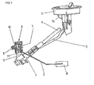
- FIG. 1 shows a lid formed as a flange 1, which closes an opening of an upper wall of a fuel tank, not shown.
- a hold-down 2 leads obliquely downwards, which carries at its free end a suction jet pump 3.
- Saugstrahlpumpe 3 performs a fuel line 4 in a tank chamber, not shown, in which an electric fuel pump for conveying Fuel is arranged to an injection system.
- a holding part 5 On the housing of the suction jet pump 3, a holding part 5 is arranged, on which a level sensor 6 is seated as an electrical component for this tank chamber.
- the level sensor 6 has a lever arm 7 with a float 8 at the free end.
- the lever arm 7 is mounted with an axis 9 in a socket 10, which is integrally formed on the carrier 11 of the level sensor 6.
- the level sensor 6 has a substrate 12 on which a resistor network in thick film technology is arranged with a potentiometer. On the potentiometer travels a sliding contact in response to the pivotal movement of the lever arm 7.
- the substrate is connected to electrical terminals, which in turn are connected to electrical signal lines 13, the lead from the holding part 5, through the flange 1 to the transmitter.
- the connection of the electrical connections to the electrical signal lines 13 is described in the following figures.
- the holding part 5 in FIG. 2 can according to FIG. 1 be formed on the housing of a suction jet pump. But it is also conceivable that the holding part 5 is part of other components, for. B. on a swirl pot of a conveyor unit or on a flange.
- the holding part 5 has a receptacle 14 for a first part 15 of the connector 16.
- the receptacle 14 is U-shaped, wherein the free legs 17, 18 are formed as latching hooks, in which the first part 15 of the connector 16 is clipped, so that it is fixed in the vertical direction.
- the legs 17, 18 in turn engage in recesses of the first part 15, whereby the first part 15 of the connector 16 is fixed in the horizontal direction to the holding part 5.
- the holding part 5 further has a stop 19 and latching steps 20, whose mode of operation in FIG. 4 is explained. For better clarity, the signal lines 13, which leave the first part 15 of the connector 16 in the region of the legs 17, 18, not shown.
- the carrier 11 in FIG. 3 has in the upper part locking elements 21 for receiving the substrate, not shown, of the level sensor.
- the second part 23 of the connector 16 is arranged stationary.
- the carrier 11 has a latching hook 24, the function of which is described in connection with the latching arms 25 in the following figures.
- FIG. 4 shows the device according to the invention with carrier 11 and holding part 5 in the assembled state.
- the carrier 11 is inserted in a relation to the illustration slightly rotated clockwise position with the latching hook 24 in the stop 19 of the holding part 5.
- the carrier is pivoted in the counterclockwise direction, wherein the stop 19 forms the pivot point of the pivoting movement.
- the plug formed as a second part 23 of the connector 16 enters the formed as a socket first part 15 of the connector 16.
- the pivotal movement counterclockwise is limited when the latching arms 25 of the carrier 11 with their latching hooks in the latching steps 20 of the holding part 5 intervene.
- the device in FIG. 5 shows a section through the holding part 5 and the carrier 11 perpendicular to the section according to FIG. 4 ,
- the device according to the invention also allows one-hand dismantling.
- the latching arms 25 of the carrier 11 are pressed together at their free ends, whereby the latching hooks 29 are released from the latching steps 20.
- the latching arms 26 of the second part 23 of the connector 16 are simultaneously compressed, so that itself release the latching hooks 27 from the latching steps 28.
- Neither carrier part 11 nor the second part 23 of the connector 16 is locked, so that pivoting of the carrier 11 in a clockwise direction about acting as a pivot stop 19 causes the disassembly of the carrier 11 and holding part 5 and the release of the electrical connection.
- the device according to the preceding figures is designed such that the connection of the holding part with the carrier takes place by means of a pivoting movement.
- FIG. 6 shows FIG. 6 the device in an embodiment in which the connection of the carrier 11 with the holding part 5 by a rectilinear movement from top to bottom takes place.
- the connector 16 and the carrier 11 have the same structure.
- the holding part 5 has a laterally projecting arm 30, which has a receptacle 14 for a first part 15 of the connector 16.
- the receptacle 14 is U-shaped, wherein the free legs 17, 18 are formed as latching hooks, in which the first part 15th the connector 16 is clipped.
- Next 20 acting form elements are on the arm 30 as latching steps formed, which engage with the latching hooks 29 of the support member 11.
Landscapes
- Engineering & Computer Science (AREA)
- Chemical & Material Sciences (AREA)
- Combustion & Propulsion (AREA)
- Mechanical Engineering (AREA)
- Sustainable Development (AREA)
- Life Sciences & Earth Sciences (AREA)
- General Engineering & Computer Science (AREA)
- Sustainable Energy (AREA)
- Transportation (AREA)
- Physics & Mathematics (AREA)
- Fluid Mechanics (AREA)
- General Physics & Mathematics (AREA)
- Details Of Connecting Devices For Male And Female Coupling (AREA)
Abstract
Description
- Gegenstand der Erfindung ist eine Vorrichtung zum Erstellen einer elektrischen Verbindung, bestehend aus einer elektrischen Komponente, einem Halteteil für die elektrische Komponente, elektrischen Anschlussleitungen für die elektrische Komponente, sowie einer aus zwei miteinander verbindbaren Teilen bestehenden Steckverbindung für die elektrischen Anschlussleitungen.
- Derartige Vorrichtungen finden Verwendung zum Verbinden elektrischer Komponenten, insbesondere von Kraftstoffpumpen oder Füllstandgebern in Kraftstoffbehältern von Kraftfahrzeugen. Die elektrischen Anschlussleitungen dienen beispielsweise bei einer Kraftstoffpumpe zur Stromversorgung oder bei einem Füllstandgeber, um die in Abhängigkeit vom Füllstand gewonnenen elektrischen Signale einer Auswerteelektronik zuzuführen. Sowohl Füllstandsgeber als auch Kraftstoffpumpe weisen mit Stecker oder Buchse jeweils einen Teil der Steckverbindung auf. Durch ein Verbinden mit dem jeweils anderen Teil der Steckverbindung lassen sich die Kraftstoffpumpe und der Füllstandsgeber mit einer Stromversorgung oder anderen elektrischen Baugruppen verbinden. Nachteilig hierbei ist, dass das Erstellen der elektrischen Verbindungen nach erfolgter Montage der elektrischen Komponente im Kraftstoffbehälter erfolgt. Da die elektrischen Komponenten oftmals durch eine Flanschöffnung in den Kraftstoffbehälter eingebracht teilweise bis in schwer von Hand zugänglichen Bereichen montiert werden, muss das Erstellen der elektrischen Verbindung zwangsläufig ebenfalls in diesen Bereichen erfolgen. Aufgrund der geringen Platzverhältnisse im Kraftstoffbehälter ist dabei oftmals nur eine Ein-Hand-Montage und oder eine Montage ohne Blickkontakt möglich. Zusätzlich werden durch die fehlende Sicht Fehler während der Montage begünstigt, indem Anschlussleitungen vertauscht oder nicht bis zur vollständigen Kontaktierung montiert werden. Die Folge davon ist ein Ausfall der elektrischen Komponente oder das fehlerhafte Funktionieren der elektrischen Komponente, was zeit- und kostenaufwändige Reparaturen erfordert.
- Dazu ist es bekannt, die elektrischen Anschlussleitungen mit Überlänge vorzusehen, um die Steckverbindung außerhalb des Kraftstoffbehälters zu fügen. Anschließend wurde die Steckverbindung mit den Anschlussleitungen im Kraftstoffbehälter verlegt. Aufgrund der Fahrzeugbewegungen konnte sich die Steckverbindung bewegen, was zu Kontaktunterbrechungen infolge von Reibkorrosion führen kann. Zudem können die überlangen Anschlussleitungen in den Bereich bewegter Teile, z. B. des Hebelarms des Füllstandsgebers, gelangen und dort ein Klemmen bewirken, was ebenfalls zu Fehlfunktionen führen kann. Ein Fixieren der überlangen Anschlussleitungen erfordert dagegen zusätzliche Befestigungsmittel, damit verbunden Montageaufwand und entsprechend vorhandene Verlegewege. Zudem bedingen die Befestigungsmittel und die längeren Anschlussleitungen höhere Kosten.
- Der Erfindung liegt daher die Aufgabe zugrunde, eine eingangs genannte Vorrichtung zu schaffen, welche ein einfaches und zuverlässiges Erstellen einer elektrischen Verbindung hat. Das Erstellen der elektrischen Verbindung sollte mit einer Hand, ohne Blickkontakt bei geringen Kosten möglich sein.
- Erfindungsgemäß wird die Aufgabe dadurch gelöst, dass das erste Teil der Steckverbindung an der elektrischen Komponente und das zweite Teil der Steckverbindung an dem Halteteil angeordnet ist, wobei das erste und das zweite Teil derart angeordnet sind, dass beim Verbinden der elektrischen Komponente mit dem Halteteil das erste mit dem zweiten Teil verbindbar ist.
- Mit der erfindungsgemäßen Vorrichtung wird die Steckverbindung gleichzeitig mit der Montage der elektrischen Komponente mit dem Halteteil geschlossen. Dadurch entfällt ein separates Verbinden der beiden Teile der Steckverbindung. Mit dem Wegfall dieses Montageschrittes gestaltet sich die Montage einfacher. Hinzu kommt, dass das Halteteil und die elektrische Komponente größer als eine Steckverbindung sind, so dass Montagehilfen wie Einführschrägen ebenfalls größer ausgeführt sein können, was die Handhabung wesentlich problemloser gestaltet. Überdies werden Fehlfunktionen infolge unvollständiger Kontaktierung oder Vertauschen der Anschlussleitungen ausgeschlossen. Weiter können längere Anschlussleitungen für eine Kontaktierung außerhalb des Kraftstoffbehälters und Befestigungsmittel für diese Anschlussleitungen eingespart werden.
- In einer vorteilhaften Ausgestaltung sind die beiden Teile der Steckverbindung als Stecker und Buchse ausgebildet.
- Sofern die elektrische Komponente aus mehreren Teilkomponenten besteht, ist das erste Teil an einer der Teilkomponenten angeordnet. Die Anordnung der Teilkomponente im Kraftstoffbehälter, deren Erreichbarkeit für die Montage und deren Größen können Kriterien für die Auswahl einer geeigneten Teilkomponente sein. So hat es sich als vorteilhaft herausgestellt, bei einem Füllstandsgeber das erste Teil der Steckverbindung am Träger für das Widerstandsnetzwerk des Füllstandsgebers anzuordnen.
- Ein zuverlässiger Schutz gegen ein ungewolltes Lösen der Steckverbindung, z. B. infolge von Fahrzeugbewegungen, wird vermieden, wenn die Steckverbindung verriegelbar ist, wobei die Mechanik zum Ver- und Entriegeln an dem Halteteil oder einer der Teilkomponenten angeordnet ist.
- Eine vereinfachte Demontage wird erreicht, wenn die Steckverbindung über eine Zwangsentriegelung verfügt, wobei die Zwangsentriegelung durch das Entriegeln des Halteteils ausgelöst wird.
- Ein besonders hoher Integrationsgrad wird erreicht, wenn die Teile der Steckverbindung jeweils integral, d.h. einteilig, an der elektrischen Komponente und dem Halteteil ausgebildet sind. Dagegen erlaubt die lösbare Anordnung des ersten und zweiten Teils der Steckverbindung an der elektrischen Komponente und dem Halteteil die Verwendung von standardisierten Steckern und Buchsen.
- Die lösbar angeordneten Teile der Steckverbindung lassen sich besonders einfach und kostengünstig montieren, wenn sie jeweils mittels einer Rastverbindung an der elektrischen Komponente und dem Halteteil angeordnet sind.
- Zur Montage des Halteteils mit der elektrischen Komponente und damit der Steckverbindung kommt überwiegend eine geradlinige Steckbewegung zur Anwendung. Sofern die Teile der Steckverbindung leicht beweglich angeordnet sind oder entsprechend große Einführschrägen aufweisen, erlaubt die erfindungsgemäße Vorrichtung darüber hinaus eine Montage von elektrischer Komponente und Halteteil mittels einer Schwenkbewegung.
- An zwei Ausführungsbeispielen ist die Erfindung näher erläutert. Dabei zeigt die Zeichnung in
- Figur 1
- einen Füllstandgeber in einem Kraftstoffbehälter,
- Figur 2
- ein Halteteil mit einem ersten Teil einer Steckverbindung,
- Figur 3
- einen Träger mit einem zweiten Teil einer Steckverbindung und
- Figur 4
- die erfindungsgemäße Vorrichtung im Vollschnitt,
- Figur 5
- die Vorrichtung nach
Figur 4 in einem Schnitt und - Figur 6
- eine weitere Ausführungsform der Vorrichtung.
-
Figur 1 zeigt einen als Deckel ausgebildeten Flansch 1, welcher eine Öffnung einer oberen Wand eines nicht dargestellten Kraftstoffbehälters verschließt. Von diesem Flansch 1 führt ein Niederhalter 2 schräg nach unten, welcher an seinem freien Ende eine Saugstrahlpumpe 3 trägt. Von dieser Saugstrahlpumpe 3 führt eine Kraftstoffleitung 4 in eine nicht dargestellte Tankkammer, in welcher eine elektrische Kraftstoffpumpe zum Fördern von Kraftstoff zu einer Einspritzanlage angeordnet ist. Am Gehäuse der Saugstrahlpumpe 3 ist ein Halteteil 5 angeordnet, an dem ein Füllstandgeber 6 als eine elektrische Komponente für diese Tankkammer sitzt. Der Füllstandgeber 6 hat einen Hebelarm 7 mit einem Schwimmer 8 am freien Ende. Der Hebelarm 7 ist mit einer Achse 9 in einer Buchse 10 gelagert, welche am Träger 11 des Füllstandgebers 6 angeformt ist. Der Füllstandgeber 6 weist ein Substrat 12 auf, auf dem ein Widerstandsnetzwerk in Dickschichttechnologie mit einer Potentiometerbahn angeordnet ist. Auf der Potentiometerbahn bewegt sich ein Schleifkontakt in Abhängigkeit von der Schwenkbewegung des Hebelarms 7. Um die elektrischen Signale des Füllstandgebers 6 zu einer nicht dargestellten Auswerteelektronik übertragen zu können, ist das Substrat mit elektrischen Anschlüssen verbunden, die wiederum mit elektrischen Signalleitungen 13 verbunden sind, die vom Halteteil 5, durch den Flansch 1 zu der Auswerteelektronik führen. Die Verbindung der elektrischen Anschlüsse mit den elektrischen Signalleitungen 13 ist in den nachfolgenden Figuren beschrieben. - Das Halteteil 5 in
Figur 2 kann gemäßFigur 1 an dem Gehäuse einer Saugstrahlpumpe angeformt sein. Es ist aber auch denkbar, dass das Halteteil 5 Bestandteil anderer Komponenten ist, z. B. an einem Schwalltopf einer Fördereinheit oder aber an einem Flansch. Das Halteteil 5 besitzt eine Aufnahme 14 für ein erstes Teil 15 der Steckverbindung 16. Die Aufnahme 14 ist U-förmig ausgebildet, wobei die freien Schenkel 17, 18 als Rasthaken ausgebildet sind, in die das erste Teil 15 der Steckverbindung 16 eingeklipst wird, so dass es in vertikaler Richtung festliegt. Die Schenkel 17, 18 ihrerseits greifen in Ausnehmungen des ersten Teils 15 ein, wodurch das erste Teil 15 der Steckverbindung 16 in horizontaler Richtung zum Halteteil 5 festgelegt wird. Das Halteteil 5 besitzt weiter einen Anschlag 19 und Raststufen 20, deren Wirkungsweise inFigur 4 erläutert wird. Zur besseren Übersichtlichkeit sind die Signalleitungen 13, welche das erste Teil 15 der Steckverbindung 16 im Bereich der Schenkel 17, 18 verlassen, nicht dargestellt. - Der Träger 11 in
Figur 3 besitzt im oberen Teil Rastelemente 21 zur Aufnahme des nicht dargestellten Substrats des Füllstandsgebers. In einer Aufnahme 22 ist das zweite Teil 23 der Steckverbindung 16 ortsfest angeordnet. Im unteren Bereich der dargestellten Ausrichtung besitzt der Träger 11 einen Rasthaken 24, dessen Funktion in Verbindung mit den Rastarmen 25 in den folgenden Figuren beschrieben wird. -
Figur 4 zeigt die erfindungsgemäße Vorrichtung mit Träger 11 und Halteteil 5 im montierten Zustand. Während der Montage wird der Träger 11 in einer gegenüber der Darstellung leicht im Uhrzeigersinn gedrehten Position mit dem Rasthaken 24 in den Anschlag 19 des Halteteils 5 eingesetzt. Anschließend wird der Träger entgegen dem Uhrzeigersinn verschwenkt, wobei der Anschlag 19 den Drehpunkt der Schwenkbewegung bildet. Während der Schwenkbewegung gelangt das als Stecker ausgebildete zweite Teil 23 der Steckverbindung 16 in das als Buchse ausgebildete erste Teil 15 der Steckverbindung 16. Die Schwenkbewegung entgegen dem Uhrzeigersinn wird begrenzt, wenn die Rastarme 25 des Trägers 11 mit ihren Rasthaken in die Raststufen 20 des Halteteils 5 eingreifen. Genau in dieser Position verrasten die Rastarme 26 mit ihren Rasthaken 27 des zweiten Teils 23 der Steckverbindung 16 mit den Raststufen 28 des ersten Teils 15 der Steckverbindung 16. Auf diese Weise wird allein mit der Bewegung des Trägers 11 sowohl die Montage des Trägers am Halteteil als auch die elektrische Kontaktierung bewirkt. Eine zusätzliche Handhabung zur Kontaktierung elektrischer Leitungen ist nicht erforderlich, was eine ein-Hand-Montage auch ohne Sichtkontakt ermöglicht. - Die Vorrichtung in
Figur 5 zeigt einen Schnitt durch das Halteteil 5 und den Träger 11 senkrecht zum Schnitt gemäßFigur 4 . Die erfindungsgemäße Vorrichtung erlaubt auch die Ein-Hand-Demontage. Hierzu werden die Rastarme 25 des Trägers 11 an ihren freien Enden zusammengedrückt, wodurch sich die Rasthaken 29 aus den Raststufen 20 lösen. Mit dem Zusammendrücken der Rastarme 25 werden gleichzeitig die Rastarme 26 des zweiten Teils 23 der Steckverbindung 16 zusammengedrückt, so dass sich die Rasthaken 27 aus den Raststufen 28 lösen. Weder Trägerteil 11 noch das zweite Teil 23 der Steckverbindung 16 ist verriegelt, so dass ein Verschwenken des Trägers 11 im Uhrzeigersinn um den als Drehpunkt wirkenden Anschlag 19 die Demontage von Träger 11 und Halteteil 5 als auch das Lösen der elektrischen Verbindung bewirkt. - Die Vorrichtung gemäß den vorhergehenden Figuren ist derart ausgebildet, dass das Verbinden des Halteteils mit dem Träger mittels einer Schwenkbewegung erfolgt. Im Gegensatz dazu zeigt
Figur 6 die Vorrichtung in einer Ausgestaltung, bei der das Verbinden des Trägers 11 mit dem Halteteil 5 durch eine geradlinige Bewegung von oben nach unten erfolgt. Die Steckverbindung 16 und der Träger 11 besitzen den gleichen Aufbau. Das Halteteil 5 besitzt einen seitlich abstehenden Arm 30, der eine Aufnahme 14 für ein erstes Teil 15 der Steckverbindung 16. Die Aufnahme 14 ist U-förmig ausgebildet, wobei die freien Schenkel 17, 18 als Rasthaken ausgebildet sind, in die das erste Teil 15 der Steckverbindung 16 eingeklipst wird. Weiter sind am Arm 30 als Raststufen 20 wirkende Formelemente ausgebildet, die mit den Rasthaken 29 des Trägerteils 11 verrasten.
Claims (7)
- Vorrichtung zum Erstellen einer elektrischen Verbindung, bestehend aus einer elektrischen Komponente, einem Halteteil für die elektrische Komponente, elektrischen Anschlussleitungen für die elektrische Komponente, sowie einer aus zwei miteinander verbindbaren Teilen bestehenden Steckverbindung für die elektrischen Anschlussleitungen, dadurch gekennzeichnet, dass das erste Teil (15) der Steckverbindung (16) an dem Halteteil (5) und das zweite Teil (23) der Steckverbindung (16) an der elektrischen Komponente (6, 11) angeordnet ist, wobei das erste und das zweite Teil (15, 23) derart angeordnet sind, dass beim Verbinden der elektrischen Komponente (6, 11) mit dem Halteteil (5) das erste mit dem zweiten Teil (15, 23) verbindbar ist.
- Vorrichtung nach Anspruch 1, dadurch gekennzeichnet, dass die beiden Teile (15, 23) der Steckverbindung (23) als Stecker und Buchse ausgebildet sind.
- Vorrichtung nach Anspruch 1 und 2, dadurch gekennzeichnet, dass die elektrische Komponente (6) aus mehreren Teilkomponenten besteht und das erste Teil (15) an einer der Teilkomponenten (11) angeordnet ist.
- Vorrichtung nach zumindest einem der vorhergehenden Ansprüche, dadurch gekennzeichnet, dass die Steckverbindung (16) verriegelbar ist, wobei die Mechanik zum Ver- und Entriegeln an dem Halteteil (5) oder einer der Teilkomponenten (11) angeordnet ist.
- Vorrichtung nach einem der vorhergehenden Ansprüche, dadurch gekennzeichnet, dass das erste und zweite Teil (15, 23) der Steckverbindung (16) jeweils lösbar an der elektrischen Komponente (6, 11) und dem Halteteil (5) angeordnet sind.
- Vorrichtung nach Anspruch 5, dadurch gekennzeichnet, dass das erste und zweite Teil (15, 23) der Steckverbindung (16) jeweils mittels einer Rastverbindung (14, 17, 18) an der elektrischen Komponente (11) und dem Halteteil (6) angeordnet sind.
- Vorrichtung nach zumindest einem der vorhergehenden Ansprüche, dadurch gekennzeichnet, dass die beiden Teile (15, 23) der Steckverbindung (16) miteinander verbunden werden, indem die elektrischen Komponenten (6, 11) mit dem Halteteil (11) mittels einer geradlinigen Steckbewegung oder einer Schwenkbewegung montiert werden.
Applications Claiming Priority (1)
| Application Number | Priority Date | Filing Date | Title |
|---|---|---|---|
| DE201010054604 DE102010054604A1 (de) | 2010-12-15 | 2010-12-15 | Vorrichtung zum Erstellen einer elektrischen Verbindung |
Publications (2)
| Publication Number | Publication Date |
|---|---|
| EP2466105A1 true EP2466105A1 (de) | 2012-06-20 |
| EP2466105B1 EP2466105B1 (de) | 2015-09-23 |
Family
ID=45318930
Family Applications (1)
| Application Number | Title | Priority Date | Filing Date |
|---|---|---|---|
| EP11192604.4A Not-in-force EP2466105B1 (de) | 2010-12-15 | 2011-12-08 | Vorrichtung zum Erstellen einer elektrischen Verbindung |
Country Status (2)
| Country | Link |
|---|---|
| EP (1) | EP2466105B1 (de) |
| DE (1) | DE102010054604A1 (de) |
Citations (7)
| Publication number | Priority date | Publication date | Assignee | Title |
|---|---|---|---|---|
| US3366776A (en) * | 1964-05-06 | 1968-01-30 | Irwin S Knight | Holder for an electrically heated cooking vessel |
| DE3310704C2 (de) * | 1983-03-24 | 1989-03-16 | Audi AG, 8070 Ingolstadt | Flüssigkeitsstandmesseinrichtung |
| US5852545A (en) * | 1995-05-24 | 1998-12-22 | Dell Usa, L.P. | Detachable electrical and mechanical mounting mechanism for snap mounting computer speakers |
| DE19933044A1 (de) * | 1999-07-15 | 2001-01-18 | Mannesmann Vdo Ag | Füllstandsgeber für einen Flüssigkeitsbehälter und Verfahren zur Ermittlung des Füllstandes in einem Flüssigkeitsbehälter |
| DE10324779A1 (de) * | 2003-05-31 | 2004-12-23 | Daimlerchrysler Ag | Einrichtung zur Versorgung einer Brennkraftmaschine mit Kraftstoff |
| WO2006027355A2 (de) * | 2004-09-08 | 2006-03-16 | Siemens Aktiengesellschaft | Halterungseinrichtung mit einem darauf befestigten schaltgerät |
| JP2009058376A (ja) * | 2007-08-31 | 2009-03-19 | Nippon Seiki Co Ltd | 液面検出装置 |
-
2010
- 2010-12-15 DE DE201010054604 patent/DE102010054604A1/de not_active Ceased
-
2011
- 2011-12-08 EP EP11192604.4A patent/EP2466105B1/de not_active Not-in-force
Patent Citations (7)
| Publication number | Priority date | Publication date | Assignee | Title |
|---|---|---|---|---|
| US3366776A (en) * | 1964-05-06 | 1968-01-30 | Irwin S Knight | Holder for an electrically heated cooking vessel |
| DE3310704C2 (de) * | 1983-03-24 | 1989-03-16 | Audi AG, 8070 Ingolstadt | Flüssigkeitsstandmesseinrichtung |
| US5852545A (en) * | 1995-05-24 | 1998-12-22 | Dell Usa, L.P. | Detachable electrical and mechanical mounting mechanism for snap mounting computer speakers |
| DE19933044A1 (de) * | 1999-07-15 | 2001-01-18 | Mannesmann Vdo Ag | Füllstandsgeber für einen Flüssigkeitsbehälter und Verfahren zur Ermittlung des Füllstandes in einem Flüssigkeitsbehälter |
| DE10324779A1 (de) * | 2003-05-31 | 2004-12-23 | Daimlerchrysler Ag | Einrichtung zur Versorgung einer Brennkraftmaschine mit Kraftstoff |
| WO2006027355A2 (de) * | 2004-09-08 | 2006-03-16 | Siemens Aktiengesellschaft | Halterungseinrichtung mit einem darauf befestigten schaltgerät |
| JP2009058376A (ja) * | 2007-08-31 | 2009-03-19 | Nippon Seiki Co Ltd | 液面検出装置 |
Also Published As
| Publication number | Publication date |
|---|---|
| EP2466105B1 (de) | 2015-09-23 |
| DE102010054604A1 (de) | 2012-06-21 |
Similar Documents
| Publication | Publication Date | Title |
|---|---|---|
| EP2209169B1 (de) | Elektrisches Gerät | |
| DE102018113365A1 (de) | Modulares Steckverbindersystem | |
| DE102013213336A1 (de) | Elektrischer steckverbinder und steckverbindersystem für ein elektro- oder hybridfahrzeug | |
| DE102013211208A1 (de) | Stecker und Steckverbinderanordnung | |
| DE102014205744B4 (de) | Steuergerät für ein Fahrzeugheizgerät | |
| WO2011054542A2 (de) | Vorrichtung zur aufnahme von elektrischen bauteilen | |
| EP3446373B1 (de) | Steckkontaktset und verfahren zum prüfen einer verrastung des steckkontaktsets | |
| WO2019025140A1 (de) | Elektrisches reiheneinbaugerät und reiheneinbaugeräte-anordnung | |
| EP2625750B1 (de) | Elektrischer clipverbinder, elektrische clipverbindung sowie konfektioniertes elektrisches kabel | |
| DE202014103376U1 (de) | Geräteanschlusssystem mit integriertem Schutzleiteranschluss für elektrische Geräte | |
| DE102007021162B4 (de) | Induktive Winkelsensoreinheit | |
| EP2466105B1 (de) | Vorrichtung zum Erstellen einer elektrischen Verbindung | |
| EP2211599B1 (de) | Baugruppe und Baugruppenträger | |
| EP2978075A2 (de) | Stecker, geräteanschlusssystem mit integriertem schutzleiteranschluss für elektrische geräte und elektrogerät | |
| DE102020123097A1 (de) | Anschlussadapter für eine Antriebsvorrichtung | |
| DE102009028333B4 (de) | Steckverbindersystem mit Möglichkeit zum Erkennen einer Falschsteckung durch Kurzschlussverbindung | |
| DE102014115384A1 (de) | Prüfkabel sowie Buchsenadapter für ein Prüfkabel | |
| DE102013210286A1 (de) | Verbindergehäuse sowie elektrischer, elektronischer oder elektrooptischer Verbinder | |
| EP2648285B1 (de) | Steckverbinder zur Montage in eine Gehäuseöffnung eines Gehäuses | |
| DE102009023292B4 (de) | Elektrischer Verbinder mit Kontaktbrücke und Verfahren zum Montieren der Kontaktbrücke | |
| DE102016116526A1 (de) | Erdungsvorrichtung, insbesondere Erdungsschuh | |
| DE102015222124A1 (de) | Stecksystem mit Sicherheitsfunktion | |
| WO2006008217A1 (de) | Sensor zur messung der position eines stellgliedes | |
| DE102014213957B4 (de) | Elektronikmodul mit eingesteckter elektrischer Kontaktierung | |
| DE102007042174A1 (de) | Elektrisches Schaltgerät für ein Kraftfahrzeug |
Legal Events
| Date | Code | Title | Description |
|---|---|---|---|
| PUAI | Public reference made under article 153(3) epc to a published international application that has entered the european phase |
Free format text: ORIGINAL CODE: 0009012 |
|
| AK | Designated contracting states |
Kind code of ref document: A1 Designated state(s): AL AT BE BG CH CY CZ DE DK EE ES FI FR GB GR HR HU IE IS IT LI LT LU LV MC MK MT NL NO PL PT RO RS SE SI SK SM TR |
|
| AX | Request for extension of the european patent |
Extension state: BA ME |
|
| 17P | Request for examination filed |
Effective date: 20121220 |
|
| 17Q | First examination report despatched |
Effective date: 20130716 |
|
| GRAP | Despatch of communication of intention to grant a patent |
Free format text: ORIGINAL CODE: EPIDOSNIGR1 |
|
| RIC1 | Information provided on ipc code assigned before grant |
Ipc: H01R 24/68 20110101ALI20140916BHEP Ipc: F02M 37/10 20060101AFI20140916BHEP Ipc: B60K 15/03 20060101ALI20140916BHEP Ipc: G01F 23/36 20060101ALI20140916BHEP |
|
| INTG | Intention to grant announced |
Effective date: 20141015 |
|
| GRAP | Despatch of communication of intention to grant a patent |
Free format text: ORIGINAL CODE: EPIDOSNIGR1 |
|
| INTG | Intention to grant announced |
Effective date: 20150413 |
|
| GRAS | Grant fee paid |
Free format text: ORIGINAL CODE: EPIDOSNIGR3 |
|
| GRAA | (expected) grant |
Free format text: ORIGINAL CODE: 0009210 |
|
| AK | Designated contracting states |
Kind code of ref document: B1 Designated state(s): AL AT BE BG CH CY CZ DE DK EE ES FI FR GB GR HR HU IE IS IT LI LT LU LV MC MK MT NL NO PL PT RO RS SE SI SK SM TR |
|
| REG | Reference to a national code |
Ref country code: GB Ref legal event code: FG4D Free format text: NOT ENGLISH |
|
| REG | Reference to a national code |
Ref country code: CH Ref legal event code: EP |
|
| REG | Reference to a national code |
Ref country code: AT Ref legal event code: REF Ref document number: 751390 Country of ref document: AT Kind code of ref document: T Effective date: 20151015 |
|
| REG | Reference to a national code |
Ref country code: IE Ref legal event code: FG4D Free format text: LANGUAGE OF EP DOCUMENT: GERMAN |
|
| REG | Reference to a national code |
Ref country code: DE Ref legal event code: R096 Ref document number: 502011007921 Country of ref document: DE |
|
| REG | Reference to a national code |
Ref country code: FR Ref legal event code: PLFP Year of fee payment: 5 |
|
| REG | Reference to a national code |
Ref country code: NL Ref legal event code: MP Effective date: 20150923 |
|
| PG25 | Lapsed in a contracting state [announced via postgrant information from national office to epo] |
Ref country code: GR Free format text: LAPSE BECAUSE OF FAILURE TO SUBMIT A TRANSLATION OF THE DESCRIPTION OR TO PAY THE FEE WITHIN THE PRESCRIBED TIME-LIMIT Effective date: 20151224 Ref country code: LV Free format text: LAPSE BECAUSE OF FAILURE TO SUBMIT A TRANSLATION OF THE DESCRIPTION OR TO PAY THE FEE WITHIN THE PRESCRIBED TIME-LIMIT Effective date: 20150923 Ref country code: NO Free format text: LAPSE BECAUSE OF FAILURE TO SUBMIT A TRANSLATION OF THE DESCRIPTION OR TO PAY THE FEE WITHIN THE PRESCRIBED TIME-LIMIT Effective date: 20151223 Ref country code: FI Free format text: LAPSE BECAUSE OF FAILURE TO SUBMIT A TRANSLATION OF THE DESCRIPTION OR TO PAY THE FEE WITHIN THE PRESCRIBED TIME-LIMIT Effective date: 20150923 Ref country code: LT Free format text: LAPSE BECAUSE OF FAILURE TO SUBMIT A TRANSLATION OF THE DESCRIPTION OR TO PAY THE FEE WITHIN THE PRESCRIBED TIME-LIMIT Effective date: 20150923 |
|
| REG | Reference to a national code |
Ref country code: LT Ref legal event code: MG4D |
|
| PG25 | Lapsed in a contracting state [announced via postgrant information from national office to epo] |
Ref country code: HR Free format text: LAPSE BECAUSE OF FAILURE TO SUBMIT A TRANSLATION OF THE DESCRIPTION OR TO PAY THE FEE WITHIN THE PRESCRIBED TIME-LIMIT Effective date: 20150923 Ref country code: RS Free format text: LAPSE BECAUSE OF FAILURE TO SUBMIT A TRANSLATION OF THE DESCRIPTION OR TO PAY THE FEE WITHIN THE PRESCRIBED TIME-LIMIT Effective date: 20150923 Ref country code: SE Free format text: LAPSE BECAUSE OF FAILURE TO SUBMIT A TRANSLATION OF THE DESCRIPTION OR TO PAY THE FEE WITHIN THE PRESCRIBED TIME-LIMIT Effective date: 20150923 |
|
| PG25 | Lapsed in a contracting state [announced via postgrant information from national office to epo] |
Ref country code: NL Free format text: LAPSE BECAUSE OF FAILURE TO SUBMIT A TRANSLATION OF THE DESCRIPTION OR TO PAY THE FEE WITHIN THE PRESCRIBED TIME-LIMIT Effective date: 20150923 |
|
| PG25 | Lapsed in a contracting state [announced via postgrant information from national office to epo] |
Ref country code: CZ Free format text: LAPSE BECAUSE OF FAILURE TO SUBMIT A TRANSLATION OF THE DESCRIPTION OR TO PAY THE FEE WITHIN THE PRESCRIBED TIME-LIMIT Effective date: 20150923 Ref country code: ES Free format text: LAPSE BECAUSE OF FAILURE TO SUBMIT A TRANSLATION OF THE DESCRIPTION OR TO PAY THE FEE WITHIN THE PRESCRIBED TIME-LIMIT Effective date: 20150923 Ref country code: EE Free format text: LAPSE BECAUSE OF FAILURE TO SUBMIT A TRANSLATION OF THE DESCRIPTION OR TO PAY THE FEE WITHIN THE PRESCRIBED TIME-LIMIT Effective date: 20150923 Ref country code: IS Free format text: LAPSE BECAUSE OF FAILURE TO SUBMIT A TRANSLATION OF THE DESCRIPTION OR TO PAY THE FEE WITHIN THE PRESCRIBED TIME-LIMIT Effective date: 20160123 Ref country code: SK Free format text: LAPSE BECAUSE OF FAILURE TO SUBMIT A TRANSLATION OF THE DESCRIPTION OR TO PAY THE FEE WITHIN THE PRESCRIBED TIME-LIMIT Effective date: 20150923 Ref country code: IT Free format text: LAPSE BECAUSE OF FAILURE TO SUBMIT A TRANSLATION OF THE DESCRIPTION OR TO PAY THE FEE WITHIN THE PRESCRIBED TIME-LIMIT Effective date: 20150923 |
|
| PG25 | Lapsed in a contracting state [announced via postgrant information from national office to epo] |
Ref country code: BE Free format text: LAPSE BECAUSE OF NON-PAYMENT OF DUE FEES Effective date: 20151231 Ref country code: PL Free format text: LAPSE BECAUSE OF FAILURE TO SUBMIT A TRANSLATION OF THE DESCRIPTION OR TO PAY THE FEE WITHIN THE PRESCRIBED TIME-LIMIT Effective date: 20150923 Ref country code: RO Free format text: LAPSE BECAUSE OF FAILURE TO SUBMIT A TRANSLATION OF THE DESCRIPTION OR TO PAY THE FEE WITHIN THE PRESCRIBED TIME-LIMIT Effective date: 20150923 Ref country code: PT Free format text: LAPSE BECAUSE OF FAILURE TO SUBMIT A TRANSLATION OF THE DESCRIPTION OR TO PAY THE FEE WITHIN THE PRESCRIBED TIME-LIMIT Effective date: 20160125 |
|
| REG | Reference to a national code |
Ref country code: DE Ref legal event code: R097 Ref document number: 502011007921 Country of ref document: DE |
|
| PG25 | Lapsed in a contracting state [announced via postgrant information from national office to epo] |
Ref country code: LU Free format text: LAPSE BECAUSE OF FAILURE TO SUBMIT A TRANSLATION OF THE DESCRIPTION OR TO PAY THE FEE WITHIN THE PRESCRIBED TIME-LIMIT Effective date: 20151208 Ref country code: MC Free format text: LAPSE BECAUSE OF FAILURE TO SUBMIT A TRANSLATION OF THE DESCRIPTION OR TO PAY THE FEE WITHIN THE PRESCRIBED TIME-LIMIT Effective date: 20150923 |
|
| PLBE | No opposition filed within time limit |
Free format text: ORIGINAL CODE: 0009261 |
|
| REG | Reference to a national code |
Ref country code: CH Ref legal event code: PL |
|
| STAA | Information on the status of an ep patent application or granted ep patent |
Free format text: STATUS: NO OPPOSITION FILED WITHIN TIME LIMIT |
|
| GBPC | Gb: european patent ceased through non-payment of renewal fee |
Effective date: 20151223 |
|
| 26N | No opposition filed |
Effective date: 20160624 |
|
| PG25 | Lapsed in a contracting state [announced via postgrant information from national office to epo] |
Ref country code: DK Free format text: LAPSE BECAUSE OF FAILURE TO SUBMIT A TRANSLATION OF THE DESCRIPTION OR TO PAY THE FEE WITHIN THE PRESCRIBED TIME-LIMIT Effective date: 20150923 |
|
| REG | Reference to a national code |
Ref country code: IE Ref legal event code: MM4A |
|
| PG25 | Lapsed in a contracting state [announced via postgrant information from national office to epo] |
Ref country code: CH Free format text: LAPSE BECAUSE OF NON-PAYMENT OF DUE FEES Effective date: 20151231 Ref country code: IE Free format text: LAPSE BECAUSE OF NON-PAYMENT OF DUE FEES Effective date: 20151208 Ref country code: LI Free format text: LAPSE BECAUSE OF NON-PAYMENT OF DUE FEES Effective date: 20151231 Ref country code: GB Free format text: LAPSE BECAUSE OF NON-PAYMENT OF DUE FEES Effective date: 20151223 |
|
| PG25 | Lapsed in a contracting state [announced via postgrant information from national office to epo] |
Ref country code: SI Free format text: LAPSE BECAUSE OF FAILURE TO SUBMIT A TRANSLATION OF THE DESCRIPTION OR TO PAY THE FEE WITHIN THE PRESCRIBED TIME-LIMIT Effective date: 20150923 |
|
| REG | Reference to a national code |
Ref country code: FR Ref legal event code: PLFP Year of fee payment: 6 |
|
| PG25 | Lapsed in a contracting state [announced via postgrant information from national office to epo] |
Ref country code: BG Free format text: LAPSE BECAUSE OF FAILURE TO SUBMIT A TRANSLATION OF THE DESCRIPTION OR TO PAY THE FEE WITHIN THE PRESCRIBED TIME-LIMIT Effective date: 20150923 Ref country code: HU Free format text: LAPSE BECAUSE OF FAILURE TO SUBMIT A TRANSLATION OF THE DESCRIPTION OR TO PAY THE FEE WITHIN THE PRESCRIBED TIME-LIMIT; INVALID AB INITIO Effective date: 20111208 Ref country code: SM Free format text: LAPSE BECAUSE OF FAILURE TO SUBMIT A TRANSLATION OF THE DESCRIPTION OR TO PAY THE FEE WITHIN THE PRESCRIBED TIME-LIMIT Effective date: 20150923 |
|
| PG25 | Lapsed in a contracting state [announced via postgrant information from national office to epo] |
Ref country code: CY Free format text: LAPSE BECAUSE OF FAILURE TO SUBMIT A TRANSLATION OF THE DESCRIPTION OR TO PAY THE FEE WITHIN THE PRESCRIBED TIME-LIMIT Effective date: 20150923 |
|
| PG25 | Lapsed in a contracting state [announced via postgrant information from national office to epo] |
Ref country code: MT Free format text: LAPSE BECAUSE OF FAILURE TO SUBMIT A TRANSLATION OF THE DESCRIPTION OR TO PAY THE FEE WITHIN THE PRESCRIBED TIME-LIMIT Effective date: 20150923 Ref country code: TR Free format text: LAPSE BECAUSE OF FAILURE TO SUBMIT A TRANSLATION OF THE DESCRIPTION OR TO PAY THE FEE WITHIN THE PRESCRIBED TIME-LIMIT Effective date: 20150923 |
|
| REG | Reference to a national code |
Ref country code: FR Ref legal event code: PLFP Year of fee payment: 7 |
|
| REG | Reference to a national code |
Ref country code: AT Ref legal event code: MM01 Ref document number: 751390 Country of ref document: AT Kind code of ref document: T Effective date: 20161208 |
|
| PG25 | Lapsed in a contracting state [announced via postgrant information from national office to epo] |
Ref country code: AT Free format text: LAPSE BECAUSE OF NON-PAYMENT OF DUE FEES Effective date: 20161208 |
|
| PG25 | Lapsed in a contracting state [announced via postgrant information from national office to epo] |
Ref country code: MK Free format text: LAPSE BECAUSE OF FAILURE TO SUBMIT A TRANSLATION OF THE DESCRIPTION OR TO PAY THE FEE WITHIN THE PRESCRIBED TIME-LIMIT Effective date: 20150923 |
|
| PG25 | Lapsed in a contracting state [announced via postgrant information from national office to epo] |
Ref country code: AL Free format text: LAPSE BECAUSE OF FAILURE TO SUBMIT A TRANSLATION OF THE DESCRIPTION OR TO PAY THE FEE WITHIN THE PRESCRIBED TIME-LIMIT Effective date: 20150923 |
|
| PGFP | Annual fee paid to national office [announced via postgrant information from national office to epo] |
Ref country code: FR Payment date: 20181220 Year of fee payment: 8 |
|
| PGFP | Annual fee paid to national office [announced via postgrant information from national office to epo] |
Ref country code: DE Payment date: 20181231 Year of fee payment: 8 |
|
| REG | Reference to a national code |
Ref country code: DE Ref legal event code: R081 Ref document number: 502011007921 Country of ref document: DE Owner name: VITESCO TECHNOLOGIES GMBH, DE Free format text: FORMER OWNER: CONTINENTAL AUTOMOTIVE GMBH, 30165 HANNOVER, DE |
|
| REG | Reference to a national code |
Ref country code: DE Ref legal event code: R119 Ref document number: 502011007921 Country of ref document: DE |
|
| PG25 | Lapsed in a contracting state [announced via postgrant information from national office to epo] |
Ref country code: DE Free format text: LAPSE BECAUSE OF NON-PAYMENT OF DUE FEES Effective date: 20200701 Ref country code: FR Free format text: LAPSE BECAUSE OF NON-PAYMENT OF DUE FEES Effective date: 20191231 |