EP2466076A1 - Hochtemperaturdampfventil - Google Patents
Hochtemperaturdampfventil Download PDFInfo
- Publication number
- EP2466076A1 EP2466076A1 EP10196025A EP10196025A EP2466076A1 EP 2466076 A1 EP2466076 A1 EP 2466076A1 EP 10196025 A EP10196025 A EP 10196025A EP 10196025 A EP10196025 A EP 10196025A EP 2466076 A1 EP2466076 A1 EP 2466076A1
- Authority
- EP
- European Patent Office
- Prior art keywords
- spacer
- valve
- casing
- actuator
- connector
- Prior art date
- Legal status (The legal status is an assumption and is not a legal conclusion. Google has not performed a legal analysis and makes no representation as to the accuracy of the status listed.)
- Withdrawn
Links
Images


Classifications
-
- F—MECHANICAL ENGINEERING; LIGHTING; HEATING; WEAPONS; BLASTING
- F16—ENGINEERING ELEMENTS AND UNITS; GENERAL MEASURES FOR PRODUCING AND MAINTAINING EFFECTIVE FUNCTIONING OF MACHINES OR INSTALLATIONS; THERMAL INSULATION IN GENERAL
- F16K—VALVES; TAPS; COCKS; ACTUATING-FLOATS; DEVICES FOR VENTING OR AERATING
- F16K27/00—Construction of housing; Use of materials therefor
- F16K27/12—Covers for housings
-
- F—MECHANICAL ENGINEERING; LIGHTING; HEATING; WEAPONS; BLASTING
- F01—MACHINES OR ENGINES IN GENERAL; ENGINE PLANTS IN GENERAL; STEAM ENGINES
- F01D—NON-POSITIVE DISPLACEMENT MACHINES OR ENGINES, e.g. STEAM TURBINES
- F01D17/00—Regulating or controlling by varying flow
- F01D17/10—Final actuators
- F01D17/12—Final actuators arranged in stator parts
- F01D17/14—Final actuators arranged in stator parts varying effective cross-sectional area of nozzles or guide conduits
- F01D17/141—Final actuators arranged in stator parts varying effective cross-sectional area of nozzles or guide conduits by means of shiftable members or valves obturating part of the flow path
- F01D17/145—Final actuators arranged in stator parts varying effective cross-sectional area of nozzles or guide conduits by means of shiftable members or valves obturating part of the flow path by means of valves, e.g. for steam turbines
-
- F—MECHANICAL ENGINEERING; LIGHTING; HEATING; WEAPONS; BLASTING
- F16—ENGINEERING ELEMENTS AND UNITS; GENERAL MEASURES FOR PRODUCING AND MAINTAINING EFFECTIVE FUNCTIONING OF MACHINES OR INSTALLATIONS; THERMAL INSULATION IN GENERAL
- F16K—VALVES; TAPS; COCKS; ACTUATING-FLOATS; DEVICES FOR VENTING OR AERATING
- F16K49/00—Means in or on valves for heating or cooling
Definitions
- the disclosure relates generally to high temperature steam valves with actuators and specifically to means for limiting the heat exposure of such actuators.
- high temperature shall be taken to mean greater than about 650 degrees Celsius.
- valve bodies are required not only for valve bodies but also for valve actuators.
- problems caused by high temperature typically cannot be solved merely by material selection. Instead, means have to be employed to limit temperature exposure of the actuator.
- US 7,481,058 B2 describes one such cooling configuration in which the valve casing is provided with cooling ports and means to pass cooling medium through these ports. Such configurations are complex and further require the configuration and supply of a cooling medium.
- An alternate solution is to provide a distance spacer, made of a high hot strength material, between the valve casing and the actuator. Having a high hot strength means the connector spacer can tolerate the conducted heat energy from the valve casing while its length further enables it to lose some of this heat convectively, thus creating a temperature gradient between the casing and the actuator. By configuring the spacer length, a significantly large temperature gradient can be created that ensures the actuator is not exposed to excessive temperatures. However, in providing the temperature gradient, the space must be configured to withstand the high temperature of the valve casing. For valves in high steam temperature service typically this means the spacer must be made of expensive nickel-alloy.
- a steam valve is disclosed that provides an alternate means to overcome the problem of conductive heat exposure of a steam valve actuator in high temperature steam service.
- Embodiments attempt to address this problem by means of the subject matter of the independent claim.
- Advantageous embodiments are given in the dependent claims.
- the invention is based on the general idea of providing a high temperature steam valve spacer between an actuator and casing that has graded temperature resistance.
- a high temperature steam valve comprising a casing, an actuator for operating the valve, and a connector that is at one end is fixed adjacent to the casing and at a second end fixed to an actuator.
- the connector has first and second spacers, each with first and second distal ends. The first end of the first spacer is fixed adjacent to the casing and its second end is fixed adjacent to the second spacer. The second end of the second spacer is then further fixed adjacent to the actuator.
- the second spacer is made of a material with a lower hot strength than the first spacer.
- the first spacer length is configured to ensure, during valve operation, the second spacer is not exposed to a temperature that exceeds its hot strength while being configured short enough to minimise the use of hot strength material.
- the first spacer comprises a plurality of distance spacers that are spaced apart from each other so as to create an air gap therebetween. This gap reduces the thermal heat energy transferred to the first spacer from the casing.
- the spacers may further include surface area increasing features that increase the convective heat loss from the spacers and thus increase the thermal gradient along their extensional length. In this way, shorter spacers, with lower material weight, can be provided.
- screw means fix the first spacer to the second spacer and the first spacer to the casing respectively.
- the same screw means may be used to fix the first spacer, the second spacer and the casing together.
- the screw means provides an alternative to welding that overcomes problems of welding together dissimilar metals.
- a heat-insulating member typically made of ceramic or a metal with low heat conductivity, is located between the first spacer and the casing.
- the flange of the first spacer to the casing, the flange of the first spacer to the second spacer, or the flange of the second spacer to the actuator might include grooves in the split plane to further reduce the heat flow.
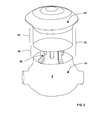
- Figs1 and 2 show a typical high temperature steam valve 5 that has a casing 10, an actuator 20 for operating the valve 5; and a connector 30 extending between the casing 10 and the actuator 20.
- the connector 30 comprises at least two distinct spacers 35,40: a first 35 with a higher hot strength fixed adjacent to the casing 10; and a second 40 with lower hot strength section that is fixed adjacent to the first spacer 35 and the actuator 20 such that it is between the first spacer 35 and the actuator 20.
- the first spacer 35 as it is adjacent the casing 10 and therefore exposed to the high temperatures of the casing 10, in an exemplary embodiment, is made of the same material as the casing 10. However, due to the temperature gradient across the second spacer 40, it is typically made of a material with a lower hot strength that the first spacer 35. This may be, for example, stainless steel instead of a nickel alloy. Further heat loss along the extensional length of the second spacer 40 also results in a lowering of the temperature at the distal end of the second spacer 40. In an exemplary embodiment, the length of the second spacer 40 is configured, in view of this temperature gradient, to ensure the actuator 20 is not exposed to excessive temperature.
- the second spacer 40 has an extended portion 46 spanning between first and second distal ends that each having a face 42, wherein the face 42 of the first end is fixed adjacent to the second end of the first spacer 35 and the face 42 of the second end is fixed adjacent to the actuator 20.
- one or both faces 42 of the second spacer 40 include grooves 45, as shown in Figs 6 and 7 , which may be formed in the radial direction, circumferential direction or a direction between these two extremes. The purpose of the grooves 45 is to limit surface contact between the first and second spacers 35 40 thus reducing the conductive heat transfer rate.
- the minimum extensional length of the first spacer 35 required to ensure sufficient convective heat loss from the first spacer 35 and the second spacer 40 and thus ensure that, in operation, the hot strength of the second spacer 40 and the actuator 20 are not exceeded.
- these factors include but are not limited to, casing 10 temperature, first spacer 35 surface areas per extensional length, the thermal conductivity of the material of the spacers 35, 40, ambient temperature and the presence of any insulation or other means that may limit convective heat loss.
- the first spacer 35 is a unitary hollow cylindrical spacer.
- "Unitary” in this context means, “made of one piece ".
- the first spacer 35 comprises a plurality of distance spacers 36 spaced apart from each other so as to create an air gap therebetween.
- the contact surface between the first spacer 35 and casing 10 may be reduced thus reducing the total conducted thermal energy provided to the first spacer 35.
- the distance spacers 36 being individual spacers, the surface area to volume ratio of the first spacer 35 is increased so by increasing convective losses from the first spacer 35 resulting in a steeper temperature gradient thus enabling shortening of the first spacer 35. All these factors combined to reduce the quantity of potentially more expensive high hot strength material that must be used to form the first spacer 35 so as to shield the actuator 20.
- the second spacer 40 includes openings 47, in the extended portion 46.
- the purpose of the openings is to reducing heat flow across of the second spacer 40.
- the first spacer 35 is provided with surface area increasing feature or features.
- Such features include surface roughing, surface grooves, and/or well-known surface configurations that increase the surface area of a spacer.
- the casing 10 and the first spacer 35 are made of similar material to ensure that both features are capable to withstanding similar thermal stresses.
- Fig 3 shows various exemplary embodiments in which screw means 38 are used to fix the first spacer 35 to the second spacer 40 and the first spacer 35 to the casing 10 respectively.
- screw means 38 are used to fix the first spacer 35 and second spacer 40, and the first spacer 35 and the casing 10 together.
- the same screw means 38 fixes the first spacer 35, the second spacer 40 and the casing 10 together.
- fix means to make firm the relative location of two parts or spacers.
- Fixing may or may not include actual contact.
- a combination of welding and screw means 38 connect the various parts, such as the casing 10 and the actuator 20 and the spacers 35,40 of the connector 30, together.
- the fixing of the spacers 35, 40 to each other is achieved by a combination of powder metallurgy and hydrostatic pressing.
- powdered material of the spacers 35, 40 are placed in a common mould after which they are hydrostatically pressed. This pressing increases the temperature of powdered material to the point where the spacers 35, 40 are cast and forged together.
- the interface between the different materials of the spacers 35,40 defines the boundary between them.
- Fig. 5 shows an exemplary embodiment in which a heat-insulating member 39 is located between the first spacer 35 and the casing 10.
- These heat insulating members 39 limit heat conduction to the first spacer 35 thus positively influencing the required extensional lengths of these spacers 35 i.e. enabling them to be made shorter.
- the heat-insulating member 39 is made of ceramic due to its excellent heat insulation properties. However as ceramic cannot be welded to metals, the ceramic parts are fitted by screw means 38.
- an additional or alternative heat-insulating member 39 is located between the first and the second spacers 35,40.
- an additional or alternative heat-insulating member 39 is located between the second spacer 40 and the actuator 20.
Priority Applications (5)
| Application Number | Priority Date | Filing Date | Title |
|---|---|---|---|
| EP10196025A EP2466076A1 (de) | 2010-12-20 | 2010-12-20 | Hochtemperaturdampfventil |
| DE102011120807A DE102011120807A1 (de) | 2010-12-20 | 2011-12-10 | Hochtemperatur-Dampfventil |
| US13/331,718 US9091363B2 (en) | 2010-12-20 | 2011-12-20 | High temperature steam valve |
| JP2011278687A JP5602716B2 (ja) | 2010-12-20 | 2011-12-20 | 高温蒸気弁 |
| CN201110443699.5A CN102537513B (zh) | 2010-12-20 | 2011-12-20 | 高温蒸汽阀 |
Applications Claiming Priority (1)
| Application Number | Priority Date | Filing Date | Title |
|---|---|---|---|
| EP10196025A EP2466076A1 (de) | 2010-12-20 | 2010-12-20 | Hochtemperaturdampfventil |
Publications (1)
| Publication Number | Publication Date |
|---|---|
| EP2466076A1 true EP2466076A1 (de) | 2012-06-20 |
Family
ID=43980710
Family Applications (1)
| Application Number | Title | Priority Date | Filing Date |
|---|---|---|---|
| EP10196025A Withdrawn EP2466076A1 (de) | 2010-12-20 | 2010-12-20 | Hochtemperaturdampfventil |
Country Status (5)
| Country | Link |
|---|---|
| US (1) | US9091363B2 (de) |
| EP (1) | EP2466076A1 (de) |
| JP (1) | JP5602716B2 (de) |
| CN (1) | CN102537513B (de) |
| DE (1) | DE102011120807A1 (de) |
Citations (5)
| Publication number | Priority date | Publication date | Assignee | Title |
|---|---|---|---|---|
| DE1201366B (de) * | 1960-05-11 | 1965-09-23 | Spuhr & Co M | Mit Hilfskraft steuerbares Regelventil fuer Hochdruckdampfanlagen |
| US3556463A (en) * | 1968-10-08 | 1971-01-19 | Worthington Corp | Trip valve system |
| EP1026369A1 (de) * | 1999-02-04 | 2000-08-09 | ABB Alstom Power (Schweiz) AG | Dampfturbine |
| EP1637783A1 (de) * | 2004-09-20 | 2006-03-22 | Siemens Aktiengesellschaft | Schnellschluss-Stellventilkombination für eine Dampfturbine |
| US7481058B2 (en) | 2004-09-08 | 2009-01-27 | Kabushiki Kaisha Toshiba | High temperature steam valve and steam turbine plant |
Family Cites Families (32)
| Publication number | Priority date | Publication date | Assignee | Title |
|---|---|---|---|---|
| US1891374A (en) * | 1930-05-02 | 1932-12-20 | Ehemann William | Valve |
| US2301176A (en) * | 1940-08-12 | 1942-11-10 | Harry C Elliott | Valve construction |
| US2610820A (en) * | 1946-11-15 | 1952-09-16 | Edward Valves Inc | Valve bonnet structure |
| US3290003A (en) * | 1962-10-29 | 1966-12-06 | G & H Products Corp | Valve construction facilitating removal of parts |
| US3916941A (en) | 1974-04-24 | 1975-11-04 | E Systems Inc | Throttle valve assembly |
| US4383546A (en) * | 1980-12-01 | 1983-05-17 | Ecolaire Incorporated | High temperature, high pressure valve |
| US4633897A (en) * | 1986-04-04 | 1987-01-06 | Effenberger Leo T | Actuator mount for valves |
| US4719939A (en) * | 1987-06-10 | 1988-01-19 | Conbraco Industries, Inc. | Apparatus for coupling a valve and rotary actuator |
| JP2515638Y2 (ja) * | 1989-08-25 | 1996-10-30 | エスエムシー 株式会社 | 流体制御弁 |
| JPH0443656Y2 (de) * | 1989-12-25 | 1992-10-15 | ||
| US5711510A (en) * | 1991-12-17 | 1998-01-27 | Stary; Gary M. | Pipeline valve apparatus |
| CA2086992A1 (en) * | 1993-01-08 | 1994-07-09 | Chao-Jung Wang | Manual/automatic operation interchangeable connecting seat of ball valve |
| JP3259207B2 (ja) * | 1994-06-01 | 2002-02-25 | 株式会社ケーヒン | 電動弁 |
| US5505226A (en) * | 1995-02-12 | 1996-04-09 | Breth; Newton R. | Raised actuator mount |
| JP3472650B2 (ja) * | 1995-07-24 | 2003-12-02 | 株式会社フジキン | 流体制御器 |
| US6070605A (en) * | 1999-01-25 | 2000-06-06 | General Electric Co. | Steam turbine valve disk vibration reducer |
| EP1223018B1 (de) | 2001-01-10 | 2005-05-25 | Synventive Molding Solutions B.V. | Spritzgiessvorrichtung mit einer gekühlten Führungsbüchse für eine Ventilnadel |
| US6848672B2 (en) * | 2001-10-04 | 2005-02-01 | Swagelok Company | Mounting bracket for valve actuator |
| JP4499984B2 (ja) | 2002-11-08 | 2010-07-14 | 株式会社堀場エステック | 高温対応バルブ |
| US7070165B2 (en) * | 2003-04-30 | 2006-07-04 | Invensys Building Systems, Inc. | Thermal isolator and controlled valve employing same |
| JP2007500316A (ja) * | 2003-07-25 | 2007-01-11 | スワゲロック カンパニー | バルブおよびアクチュエーターのための熱絶縁装置 |
| JP4208661B2 (ja) * | 2003-07-31 | 2009-01-14 | 株式会社東芝 | 蒸気弁装置および該蒸気弁装置を含む蒸気流制御システムを備えた蒸気タービン発電プラント |
| JP2006046110A (ja) | 2004-08-02 | 2006-02-16 | Toshiba Corp | 蒸気弁およびその製造方法 |
| US20060255309A1 (en) * | 2005-04-25 | 2006-11-16 | Marcilese Joseph P | Valve bonnet assembly |
| CN1888487A (zh) | 2005-06-29 | 2007-01-03 | 上海海星阀门总厂 | 气动和手动保温高耐腐蚀双向密封蝶阀 |
| CN1888490A (zh) | 2005-06-29 | 2007-01-03 | 上海海星阀门总厂 | 手动和电动保温高耐腐蚀双向密封蝶阀 |
| US20070018132A1 (en) * | 2005-07-22 | 2007-01-25 | Gethmann Douglas P | Multi-pitch threaded coupling |
| JP4819450B2 (ja) * | 2005-09-09 | 2011-11-24 | 株式会社山武 | 電動アクチュエータ |
| US20080017816A1 (en) | 2006-07-24 | 2008-01-24 | Arvin Technologies, Inc. | Thermal isolator for actuator and valve assembly |
| CN201081042Y (zh) | 2007-10-11 | 2008-07-02 | 杨荣水 | 带隔热保温结构的超高温阀门 |
| JP4954964B2 (ja) * | 2008-10-31 | 2012-06-20 | 日本ムーグ株式会社 | 流体弁駆動機構 |
| US8613423B2 (en) * | 2009-07-13 | 2013-12-24 | Fisher Controls International Llc | Methods and apparatus to load a valve packing |
-
2010
- 2010-12-20 EP EP10196025A patent/EP2466076A1/de not_active Withdrawn
-
2011
- 2011-12-10 DE DE102011120807A patent/DE102011120807A1/de not_active Withdrawn
- 2011-12-20 CN CN201110443699.5A patent/CN102537513B/zh not_active Expired - Fee Related
- 2011-12-20 US US13/331,718 patent/US9091363B2/en not_active Expired - Fee Related
- 2011-12-20 JP JP2011278687A patent/JP5602716B2/ja active Active
Patent Citations (5)
| Publication number | Priority date | Publication date | Assignee | Title |
|---|---|---|---|---|
| DE1201366B (de) * | 1960-05-11 | 1965-09-23 | Spuhr & Co M | Mit Hilfskraft steuerbares Regelventil fuer Hochdruckdampfanlagen |
| US3556463A (en) * | 1968-10-08 | 1971-01-19 | Worthington Corp | Trip valve system |
| EP1026369A1 (de) * | 1999-02-04 | 2000-08-09 | ABB Alstom Power (Schweiz) AG | Dampfturbine |
| US7481058B2 (en) | 2004-09-08 | 2009-01-27 | Kabushiki Kaisha Toshiba | High temperature steam valve and steam turbine plant |
| EP1637783A1 (de) * | 2004-09-20 | 2006-03-22 | Siemens Aktiengesellschaft | Schnellschluss-Stellventilkombination für eine Dampfturbine |
Also Published As
| Publication number | Publication date |
|---|---|
| US20120153208A1 (en) | 2012-06-21 |
| US9091363B2 (en) | 2015-07-28 |
| JP2012132560A (ja) | 2012-07-12 |
| JP5602716B2 (ja) | 2014-10-08 |
| CN102537513B (zh) | 2015-12-02 |
| CN102537513A (zh) | 2012-07-04 |
| DE102011120807A1 (de) | 2012-06-21 |
Similar Documents
| Publication | Publication Date | Title |
|---|---|---|
| EP1521036B1 (de) | Dichtungsanordnung | |
| US7901186B2 (en) | Seal assembly | |
| CA2929856C (en) | Monolithic tube-in matrix heat exchanger | |
| JP4931917B2 (ja) | ターボチャージャ用の円板部材 | |
| JP6085561B2 (ja) | タービンエンジンのための回り止めシュラウド | |
| EP2374998B1 (de) | Turbinenschaufel mit Radial-Kühlkanälen | |
| EP2469035B1 (de) | Gasturbinenkomponente mit einer leitkantenkühlung | |
| US20120034101A1 (en) | Turbine blade squealer tip | |
| EP3214276A1 (de) | Wärmesperre in turbinendüse und turbinenmantel | |
| US20110171018A1 (en) | Turbine nozzle assembly | |
| JP2015075118A (ja) | ガスタービンの高温ガス通路内の構成部材を冷却するための配置形式 | |
| US10487672B2 (en) | Airfoil for a gas turbine engine having insulating materials | |
| US20100229558A1 (en) | Methods and Apparatus for Providing A Sacrificial Shield For A Fuel Injector | |
| US20160305267A1 (en) | Heat shields for air seals | |
| US20100259013A1 (en) | Abradable labyrinth seal for a fluid-flow machine | |
| US8579021B2 (en) | Heat exchanger | |
| JP2009150382A (ja) | 断熱型フランジボルト | |
| JP6514509B2 (ja) | バイマテリアル適応性冷却通路を備えるタービンコンポーネント | |
| EP2466076A1 (de) | Hochtemperaturdampfventil | |
| JP5497055B2 (ja) | ターボ機械用内側筐体 | |
| JP2010112276A (ja) | タービン動翼構造 | |
| EP2540970A1 (de) | Mit flüssigem Metall gekühlte Schaufel | |
| JP2013170826A (ja) | 高温ガス炉 | |
| EP2743449A2 (de) | Drehbarer Wärmeschild einer Laufradhinterseite | |
| JPH11264347A (ja) | 高性能エンジン及びノズル用燃焼室 |
Legal Events
| Date | Code | Title | Description |
|---|---|---|---|
| PUAI | Public reference made under article 153(3) epc to a published international application that has entered the european phase |
Free format text: ORIGINAL CODE: 0009012 |
|
| AK | Designated contracting states |
Kind code of ref document: A1 Designated state(s): AL AT BE BG CH CY CZ DE DK EE ES FI FR GB GR HR HU IE IS IT LI LT LU LV MC MK MT NL NO PL PT RO RS SE SI SK SM TR |
|
| AX | Request for extension of the european patent |
Extension state: BA ME |
|
| STAA | Information on the status of an ep patent application or granted ep patent |
Free format text: STATUS: THE APPLICATION IS DEEMED TO BE WITHDRAWN |
|
| 18D | Application deemed to be withdrawn |
Effective date: 20121221 |