EP2464271B1 - Wischer - Google Patents
Wischer Download PDFInfo
- Publication number
- EP2464271B1 EP2464271B1 EP10750078.7A EP10750078A EP2464271B1 EP 2464271 B1 EP2464271 B1 EP 2464271B1 EP 10750078 A EP10750078 A EP 10750078A EP 2464271 B1 EP2464271 B1 EP 2464271B1
- Authority
- EP
- European Patent Office
- Prior art keywords
- wiper
- frame
- stem
- sleeve
- wiper plate
- Prior art date
- Legal status (The legal status is an assumption and is not a legal conclusion. Google has not performed a legal analysis and makes no representation as to the accuracy of the status listed.)
- Active
Links
Images

Classifications
-
- A—HUMAN NECESSITIES
- A47—FURNITURE; DOMESTIC ARTICLES OR APPLIANCES; COFFEE MILLS; SPICE MILLS; SUCTION CLEANERS IN GENERAL
- A47L—DOMESTIC WASHING OR CLEANING; SUCTION CLEANERS IN GENERAL
- A47L13/00—Implements for cleaning floors, carpets, furniture, walls, or wall coverings
- A47L13/10—Scrubbing; Scouring; Cleaning; Polishing
- A47L13/14—Scrubbing; Scouring; Cleaning; Polishing combined with squeezing or wringing devices
- A47L13/146—Scrubbing; Scouring; Cleaning; Polishing combined with squeezing or wringing devices having pivoting squeezing plates
-
- A—HUMAN NECESSITIES
- A47—FURNITURE; DOMESTIC ARTICLES OR APPLIANCES; COFFEE MILLS; SPICE MILLS; SUCTION CLEANERS IN GENERAL
- A47L—DOMESTIC WASHING OR CLEANING; SUCTION CLEANERS IN GENERAL
- A47L13/00—Implements for cleaning floors, carpets, furniture, walls, or wall coverings
- A47L13/10—Scrubbing; Scouring; Cleaning; Polishing
- A47L13/20—Mops
- A47L13/24—Frames for mops; Mop heads
- A47L13/254—Plate frames
- A47L13/258—Plate frames of adjustable or foldable type
Definitions
- the invention relates to a wiper, in particular a floor wiper, with a handle and with a pressing device displaceable along the handle for pressing juxtaposed against one another two pivotally mounted wiper plate wings according to claim 1.
- the invention relates to a wiper with a handle formed as a floor wiper, a wiper plate rotatably mounted at one end of the handle and having two wiper plate wings extending outwardly from the handle and extending downwardly toward each other, and one longitudinally of the handle between an upper one Use position and a lower extrusion position displaceable pressing device for pressing against each other of the two downwardly pivoted squeegee blades in the Auspresswolf, wherein the pressing device in the Auspresswolf the mop plate wings pressed against each other and releases the mop plate wings in a wiping position.
- Such a wiper which has a press fork with two opposing pressing elements, which are interconnected at mid-height via a transverse strut.
- This wiper has the disadvantage that an optimal squeezing of the liquid is not guaranteed by the flexibility of the lower portions of the pressing elements.
- From the EP 1188406 B is also a wiper with a handle and a slidably mounted in the longitudinal direction of the handle sliding sleeve, projecting from the at least two arms in the direction of a wiper device known.
- the wiper device has two mop plate wings which are pivotably mounted on a center piece between a wiping position and a wringing position and which can be given away by displacing the sliding sleeve with the arms in a wringing position.
- the arms are designed as in wiping position of the mop plates freely ending spring arms.
- This wiper has the significant disadvantage that by yielding to the Spring arms only a very inadequate Auspressgenesis is achieved.
- a similar embodiment shows the EP 1 208788 A1 and the DE 10 2006 017 426 A1 ,
- a wiper which has foldable wings of a wiper plate, which are pressed together via a lever mechanism when folding in a housing.
- the pressing force is transmitted via the individual levers on the flanks of the wiper blade, but this has the disadvantage that the lever must be laboriously stored, make the structure of the wiper complicated and thus expensive and finally exposed to contamination, the function may adversely affect by inhibiting the hinged storage.
- the WO 2004/054424 A1 described Pressvotechnisch the squeezing of the wiper plate wings.
- a pressing device in which the wiper plate wings are retracted into a press bell open on one side, which prevents lateral wandering of the wiper plate wings via a guidance of the wing on the inside of the pressing bell. While this configuration allows the squeegee blades to be squeezed out, it does not impart evenly distributed force to the squeegee blades since the squeezing force at the side of the sipe is less than at the opposite side. Furthermore, the leadership of the wiper plate wings over the entire press path requires a correspondingly elaborate press bell with arranged on the inside guide means. This in turn is not only costly to produce but also leads to a comparatively elaborate end of the wiper.
- a wiper which is characterized in that the swivel plate wings (4) folded in the swivel direction are retractable into the frame (8) such that the frame (8) exerts a pressing force in the swivel direction on the swash plate vanes (4).
- the wiper according to the invention instead of the press arms, has a closed frame which, even with a filigree and compact construction, is capable of transmitting greater forces to the mop plate wings than freely ending presser forks.
- the particular advantage of the frame is that now no longer guide elements on the mop plate are required.
- the mop plate is screwed into the frame or the frame is rotated in a suitable orientation and pressed together the mop plate in the frame, without it depends on the previous orientation, even if the frame is not round, but, for example, quadrangular , Due to the rotation of the frame and the lateral impact of the folded mop plate, a self-alignment of the mop plate is therefore now achieved.
- the wiper can advantageously be constructed in such a way according to the invention that the pressing device can be transferred optionally into an ejection position, in which it presses the mop plate wings against one another, or into a wiping position, in which it releases the mop plate leaves.
- the mop plate wings are embraced in the Auspresswolf of the frame.
- the inner surface enclosed by the frame corresponds approximately to the cross-sectional area of the mop plate wings pressed against each other;
- the distance of the opposite, acting on the upper sides of the mop plate wings frame sides is smaller than the thickness of the mop plate wings together with the double-laid, non-pressed mop cover. The smaller the distance is selected, the greater the force exerted
- the frame may for example be quadrangular, this in particular when the wiping surface facing away from the upper sides of the mop plate wings are flat.
- the frame in the Auspresswolf conforms to the tops of the mop plate wings.
- the frame has inwardly directed pressing projections and / or pressing noses and / or pressing surfaces.
- the inner surface which encloses the frame arranged perpendicular to the longitudinal direction of the stem.
- a particularly good cleaning embodiment of the wiper according to the invention is constructed such that on the frame, at least one - preferably two - scrapers are arranged such that the escaping during the squeezing process between the squeegee blades dirt and / or the moisture exiting there is stripped.
- the scraper may be formed for example as a rubber lip.
- the scraper can be arranged such that it scrapes along the side edges of the mop plate wings and / or the side edges of a mop cover during the squeezing process.
- the pressing device has a sleeve which is displaceable along the handle.
- the frame is attached directly or indirectly to the sleeve.
- the frame is fastened to the sleeve with a connecting device. This may, for example, have struts, which in itself must exert no pressing pressure on the mop plate wings.
- the connecting device may also be designed box-shaped.
- a box is provided whose lower edge part forms the frame, the middle part of which forms the connecting device and whose upper part has an opening - preferably a hole - through which the handle extends.
- This embodiment has the advantage that almost the entire squeezing device can be formed as a one-piece, open-bottom box with a hole arranged above.
- the mop plate wings are part of a mop head.
- the mop head and the handle are articulated - in particular cardanic and / or universal joint - with each other.
- this embodiment involves the risk that the pressing device when initiating the Auspressvorganges at an oblique angle to the hingedly connected to the stem mop head, so that it can lead to jamming. This risk can be taken into account that the user is given to ask the wiper perpendicular to the mop head before initiating the Auspressvorganges.
- the frame rotatably mounted about the stem centerline is.
- the frame is forcibly guided directly or indirectly in such a way that it rotates during the transfer from the wiping position into the squeezing position.
- the frame can also rotate about an axis parallel thereto, for example about an axis perpendicular to its inner surface. Due to the rotational movement, the jamming, regardless of the position of the mop head relative to the stem at the initiation of Auspressvorganges, effectively and reliably avoided.
- a forcibly guided rotation of the frame can be achieved, for example, in that the sleeve has a curved-in particular helically curved-guide groove into which a guide mandrel arranged on the stem engages.
- the handle has a curved-in particular helically curved-guide groove into which a guide pin arranged on the sleeve engages.
- a handle which can be operated independently of a rotational movement of the frame and / or the sleeve and / or the connecting device.
- a handle may be rotatably mounted relative to the sleeve.
- the handle is rotatably mounted about the same axis, as the frame and / or the sleeve.
- the handle is arranged coaxially with the sleeve.
- the handle may be tubular.
- a further advantageous embodiment of the invention is characterized in that a dirt brush is arranged on the mop plate but in particular also or on the frame, can be removed or loosened over the coarse dirt.
- a rectangular frame allows for easy and convenient arrangement of this dirt brush along part of its edge.
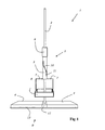
- FIG. 1 a wiper according to the invention in the wiping position
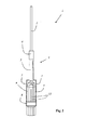
- FIG. 2 a wiper according to the invention in the Auspress thoroughly
- FIG. 3 a cross section through the mop plate wings and the frame of a wiper located in the Auspress ein.
- Fig. 1 shows a wiper 1 according to the invention, which is designed as a floor wiper.
- the wiper has a handle 2 and a pressing device 3, which is displaceable along the handle, for pressing two pivotally mounted wiper blade blades 4 against one another.
- the pressing device 3 has a sleeve 5 displaceable along the handle, with a handle 6 rotatably mounted relative to the sleeve 5.
- the sleeve 5 is fixedly connected to a frame 8 by means of connecting struts 7.
- the frame 8 and the sleeve 5, together with the struts 7, in this case perform a rotational movement about 90 degrees about the stem center axis, wherein the sleeve 5 is forced to effect this rotational movement.
- the positive guide includes a helical recess 10 in the sleeve 5, in which a guide pin 11 which is fixedly arranged on the stem 2, engages.
- the wiper head 9 has a cardan connected to the handle center piece 12, on which the mop plate wings are articulated.
- the mop plate wings have a common, squeeze mop cover 13.
- Fig. 2 shows the wiper according to the invention in the Auspresswolf.
- the frame 8 surrounds the mop plate wings 4 together with their mop cover 13, whereby the mop cover 13 is pressed out.
- a scraper 14 is arranged in each case, the laterally between the squeegee blades 4 emerging moisture and dirt scrapes off.
- Fig. 3 shows a cross section through the mop plate wings 4 together with auspressbarem mop cover 13 and the surrounding frame 8th
Landscapes
- Cleaning Implements For Floors, Carpets, Furniture, Walls, And The Like (AREA)
Description
- Die Erfindung betrifft einen Wischer, insbesondere einen Bodenwischer, mit einem Stiel und mit einer entlang des Stieles verschiebbaren Pressvorrichtung zum gegeneinander Pressen von zwei verschwenkbar gelagerten Wischplattenflügeln nach Anspruch 1.
- Insbesondere betrifft die Erfindung einen als Bodenwischer ausgebildeten Wischer mit einem Stiel, einer an einem Ende des Stiels drehbar angeordneten Wischplatte, die zwei sich von dem Stiel nach außen erstreckende und nach unten aufeinander zu schwenkbare Wischplattenflügel aufweist, und mit einer längs des Stieles zwischen einer oberen Gebrauchsstellung und einer unteren Auspressstellung verschiebbaren Pressvorrichtung zum gegeneinander Pressen der beiden an nach unten geschwenkten Wischplattenflügel in der Auspressstellung, wobei die Pressvorrichtung in der Auspressstellung die Wischplattenflügel gegeneinander presst und in einer Wischstellung die Wischplattenflügel freigibt.
- Aus der
GB 2445 727 A - Aus der
EP 1188406 B ist ferner ein Wischer mit einem Stiel und einer am Stiel in dessen Längsrichtung verschiebbar gelagerten Schiebehülse, von der wenigstens zwei Arme in Richtung einer Wischeinrichtung vorstehen, bekannt. Die Wischeinrichtung weist zwei an ein Mittelstück zwischen einer Wischstellung und einer Auswringstellung verschwenkbar gelagerte Wischplattenflügel auf, die durch Verschieben der Schiebehülse mit den Armen in Auswringstellung verschenkbar sind. Die Arme sind als in Wischstellung der Wischplatten frei endende Federarme ausgebildet. Dieser Wischer hat den erheblichen Nachteil, dass durch das Nachgeben der Federarme nur ein äußerst unzureichendes Auspressergebnis erzielt wird. Eine ähnliche Ausgestaltung zeigt dieEP 1 208788 A1 und dieDE 10 2006 017 426 A1 . - Aus der
DE 10058630 C ist ein ähnlicher Bodenwischer mit zwei - soweit technisch möglich - starren Auspressarmen bekannt. Starre Auspressarme haben den Vorteil, dass beim Auspressen eine höhere Kraft auf die Wischplatten ausgeübt werden kann, was ein verbessertes Auspressergebnis zur Folge hat. Allerdings haben starre Auspressarme den erheblichen Nachteil, dass diese besonders dick ausgebildet sein müssen, um eine gewisse Starrheit zu erreichen. Hierdurch wird der Wischer klobig, schwer und umständlich handhabbar. Darüber hinaus sind die Herstellkosten für die starren Auspressarme erheblich höher als für Federarme. - Aus der
US 2004/0148722 A1 wiederum ist ein Wischer bekannt, der klappebare Flügel einer Wischerplatte aufweist, die über ein Hebelgetriebe beim Klappen in ein Gehäuse zusammengepresst werden. Hier wird die Presskraft über die einzelnen Hebel auf die Flanken der Wischerplattenflügel übertragen, was aber den Nachteil mit sich bringt, dass die Hebel aufwändig gelagert werden müssen, den Aufbau des Wischers kompliziert und damit kostenintensiv machen und schließlich einer Verschmutzung ausgesetzt sind, die die Funktion durch Hemmung der gelenkigen Lagerung negativ beeinflussen kann. Auf ähnliche Weise, aber mit gleichen Nachteilen, realisiert die in derWO 2004/054424 A1 beschriebene Pressvorichtung das Auspressen der Wischerplattenflügel. - Aus der
DE 10 2007 057 602 A1 wiederum ist eine Pressvorrichtung bekannt, bei der die Wischerplattenflügel in eine einseitig offene Pressglocke eingezogen werden, die das seitliche Auswandern der Wischerplattenflügel über eine Führung der Flügle an der Innenseite der Pressglocke verhindert. Diese ausgestaltung erlaubt zwar ein Auspressen der Wischerplattenflügel, bringt aber keine gleichverteilte Kraft auf die wischerplattenflügel auf, da die Presskraft an der Seite der Öffnung geringer ist, als an der gegenüberliegenden Seite. Ferner erfordert die Führung der Wischerplattenflügel über den gesamten Pressweg eine entsprechend aufwändig gestaltete Pressglocke mit an der Innenseite angeordneten Führungsmitteln. Dies wiederum ist nicht nur kostenintensiv herzustellen sondern führt auch zu einem vergleichsweise aufwändigen Ende des Wischers. - Es ist die Aufgabe der vorliegenden Erfindung, einen Wischer mit gegeneinander pressbaren Wischplattenflügeln anzugeben, der kompakt ausbildbar, kostengünstig herstellbar und leicht handhabbar ist und der gleichzeitig ein Auspressergebnis ermöglicht, das zumindest genauso gut ist, wie das von Wischern mit starren Pressarmen.
- Die Aufgabe wird durch einen Wischer gelöst, der dadurch gekennzeichnet ist, dass die in Schwenkrichtung zusammengeklappten Wischplattenflügel (4) derart in den Rahmen (8) einziehbar sind, dass der Rahmen (8) eine Presskraft in Schwenkrichtung auf die Wischplattenflügel (4) ausübt.
- Im Gegensatz zu den aus dem Stand der Technik bekannten Wischern weist der erfindungsgemäße Wischer statt der Pressarme einen geschlossenen Rahmen auf, der selbst bei filigraner und kompakter Bauweise in der Lage ist, größere Kräfte auf die Wischplattenflügel zu übertragen, als frei endende Pressgabeln.
- Der besondere Vorteil des Rahmens liegt darin, dass nunmehr keine Führungselemente auf der Wischplatte mehr erforderlich sind. Insbesondere durch die Zwangsführung wird die Wischplatte in den Rahmen hineingedreht bzw. der Rahmen in eine geeignete Orientierung gedreht und die Wischplatte in dem Rahmen zusammengepresst, ohne dass es auf die vorherige Orientierung ankommt, auch wenn der Rahmen nicht rund, sondern zum Beispiel viereckig ausgebildet ist. Durch die Drehung des Rahmens und das seitliche Auftreffen der zusammengelegten Wischplatte wird daher nun eine Selbstausrichtung der Wischplatte erreicht.
- Der Wischer kann in erfindungsgemäßer Weise vorteilhaft derart aufgebaut sein, dass die Pressvorrichtung wahlweise in eine Auspressstellung, in der sie die Wischplattenflügel gegeneinander presst, oder in eine Wischstellung, in der sie die Wischplattenflügel frei gibt, überführbar ist. Insbesondere ist in erfindungsgemäßer Weise vorgesehen, dass die Wischplattenflügel in der Auspressstellung von dem Rahmen umgriffen sind.
- Bei einer besonders gut auspressenden Ausführungsform des erfindungsgemäßen Wischers ist vorgesehen, dass die von Rahmen umschlossene Innenfläche etwa der Querschnittsfläche der gegeneinander gepressten Wischplattenflügel entspricht; vorzugsweise ist der Abstand der einander gegenüberliegenden, an den Oberseiten der Wischplattenflügel angreifenden Rahmenseiten kleiner, als die Dicke der Wischplattenflügel samt dem doppelt gelegten, ungepressten Wischbezug. Je kleiner der Abstand gewählt ist, umso größer ist die ausgeübte Presskraft
- Der Rahmen kann beispielsweise viereckig ausgebildet sein, dies insbesondere dann, wenn die der Wischfläche abgewandten Oberseiten der Wischplattenflügel eben ausgebildet sind. Es ist jedoch auch möglich, beispielsweise um den Wischplattenflügeln besondere Stabilität zu geben, diese gewölbt oder gerundet auszubilden, so dass es von Vorteil ist, bei diesen Ausführungsformen, den Rahmen ebenfalls entsprechend gewölbt oder rund auszubilden. In jedem Fall ist es von Vorteil, wenn sich der Rahmen in der Auspressstellung an die Oberseiten der Wischplattenflügel anschmiegt.
- Um ein besonders gutes Auspressergebnis zu erreichen, kann alternativ oder zusätzlich auch vorgesehen sein, dass der Rahmen nach innen gerichtete Pressvorsprünge und/oder Pressnasen und/oder Pressflächen aufweist.
- Bei einer vorteilhaften Ausführungsform ist die Innenfläche, die der Rahmen einschließt, senkrecht zur Längserstreckungsrichtung des Stiels angeordnet.
- Eine besonders gut reinigende Ausführungsform des erfindungsgemäßen Wischers ist derart aufgebaut, dass an dem Rahmen, zumindest ein - vorzugsweise zwei - Abstreifer derart angeordnet sind, dass der beim Auspressvorgang zwischen den Wischplattenflügeln austretende Schmutz und/oder die dort austretende Feuchtigkeit abgestreift wird. Der Abstreifer kann beispielsweise als Gummilippe ausgebildet sein. Darüber hinaus kann der Abstreifer derart angeordnet sein, dass er beim Auspressvorgang an den Seitenkanten der Wischplattenflügel und/oder den Seitenkanten eines Wischbezugs schabend entlang streift.
- Bei einer vorteilhaften Ausführungsform des erfindungsgemäßen Wischers ist vorgesehen, dass die Pressvorrichtung eine entlang des Stiels verschiebbare Hülse aufweist. Darüber hinaus kann vorgesehen sein, dass der Rahmen direkt oder indirekt an der Hülse befestigt ist. Beispielsweise kann auch vorgesehen sein, dass der Rahmen mit einer Verbindungsvorrichtung an der Hülse befestigt ist. Diese kann beispielsweise Streben aufweisen, die für sich gesehen keinen Pressdruck auf die Wischplattenflügel ausüben müssen. Alternativ kann die Verbindungsvorrichtung auch kastenförmig ausgebildet sein.
- Bei einer besonders einfach herstellbaren und robusten Ausführungsform ist ein Kasten vorgesehen, dessen unterer Randteil den Rahmen bildet, dessen Mittelteil die Verbindungsvorrichtung bildet und dessen Oberteil eine Öffnung - vorzugsweise eine Bohrung - aufweist, durch die der Stiel verläuft. Diese Ausführungsform hat den Vorteil, dass nahezu die gesamte Auspressvorrichtung als einstückiger, unten offener Kasten mit einer oben angeordneten Bohrung ausgebildet sein kann.
- Bei einer besonderen Ausführungsform des erfindungsgemäßen Wischers ist vorgesehen, dass die Wischplattenflügel Teil eines Wischkopfes sind. Insbesondere kann, um eine gute Handhabbarkeit des Wischers in der Wischstellung zu gewährleisten, vorgesehen sein, dass der Wischkopf und der Stiel gelenkig - insbesondere kardanisch und/oder kreuzgelenkig - miteinander verbunden sind. Diese Ausführungsform birgt jedoch die Gefahr, dass die Pressvorrichtung beim Einleiten des Auspressvorganges im schiefen Winkel auf den gelenkig an den Stiel angebundenen Wischkopf trifft, so dass es zur Verklemmung kommen kann. Dieser Gefahr kann dadurch Rechnung getragen werden, dass dem Benutzer aufgegeben wird, vor Einleitung des Auspressvorganges den Wischer senkrecht zum Wischkopf zu stellen. Wesentlich einfacher und komfortabler ist eine besondere Ausführungsform des erfindungsgemäßen Wischers, bei der vorgesehen ist, dass der Rahmen um die Stielmittelachse drehbar gelagert ist. Insbesondere kann vorgesehen sein, dass der Rahmen direkt oder indirekt derart zwangsgeführt ist, dass er sich beim Überführen von der Wischstellung in die Auspressstellung dreht. Statt um die Stielmittelachse kann sich der Rahmen auch um eine hierzu parallele Achse, auch beispielsweise um eine zu seiner Innenfläche senkrechten Achse, drehen. Durch die Drehbewegung wird das Verklemmen, unabhängig von der Stellung des Wischkopfes relativ zum Stiel bei Einleitung des Auspressvorganges, wirkungsvoll und zuverlässig vermieden.
- Eine zwangsgeführte Drehbarkeit des Rahmens kann beispielsweise dadurch erreicht werden, dass die Hülse eine gekrümmte - insbesondere schraubenförmig gekrümmte - Führungsnut aufweist, in die ein am Stiel angeordneter Führungsdorn eingreift. Alternativ kann umgekehrt auch vorgesehen sein, dass der Stiel eine gekrümmte - insbesondere schraubenförmig gekrümmte - Führungsnut aufweist, in die ein an der Hülse angeordneter Führungsdorn eingreift.
- Besonders benutzerfreundlich ist eine Ausführungsform des erfindungsgemäßen Wischers, bei der ein Handgriff vorgesehen ist, der unabhängig von einer Drehbewegung des Rahmens und/oder der Hülse und/oder der Verbindungsvorrichtung bedient werden kann. Beispielsweise kann ein solcher Handgriff relativ zur Hülse drehbar gelagert sein. Insbesondere kann vorgesehen sein, dass der Handgriff um dieselbe Achse drehbar gelagert ist, wie der Rahmen und/oder die Hülse. Insbesondere kann vorgesehen sein, dass der Handgriff koaxial zu Hülse angeordnet ist. Beispielsweise kann der Handgriff rohrförmig ausgebildet sein.
- Eine weitere, vorteilhafte Ausgestaltung der Erfindung ist dadurch gekennzeichnet, dass an der Wischplatte aber insbesondere auch oder am Rahmen eine Schmutzbürste angeordnet ist, über die grober Schmutz entfernt oder gelockert werden kann. Insbesondere ein rechteckiger Rahmen ermöglicht eine leichte und günstige Anordnung dieser Schmutzbürste längs eines Teils seines Randes.
- Weitere Merkmale, Vorteile und Wirkungen der Erfindung ergeben sich aus den Unteransprüchen und der nachfolgenden Beschreibung eines bevorzugten Ausführungsbeispiels anhand der Zeichnungen, in denen der Erfindungsgegenstand schematisch dargestellt ist. Er wird anhand der Figuren nachfolgend beschrieben, wobei gleich wirkende Elemente mit denselben Bezugszeichen versehen sind. Dabei zeigt:
-
Figur 1 einen erfindungsgemäßen Wischer in der Wischstellung, -
Figur 2 einen erfindungsgemäßen Wischer in der Auspressstellung, und -
Figur 3 einen Querschnitt durch die Wischplattenflügel und den Rahmen eines in der Auspressstellung befindlichen Wischers. -
Fig. 1 zeigt einen erfindungsgemäßen Wischer 1, der als Bodenwischer ausgebildet ist. Der Wischer weist einen Stiel 2 auf und eine entlang des Stiels verschiebbare Pressvorrichtung 3 zum gegeneinander Pressen von zwei verschwenkbar gelagerten Wischplattenflügeln 4. - Die Pressvorrichtung 3 weist eine entlang des Stiels verschiebbare Hülse 5 auf, mit einem relativ zur Hülse 5 drehbar gelagerten Handgriff 6. Die Hülse 5 ist mittels Verbindungsstreben 7 mit einem Rahmen 8 fest verbunden. Durch Verschieben des Handgriffs 6 samt der Hülse 5 entlang des Stiels 2 auf den die Wischplattenflügel 4 beinhaltenden Wischkopf 9 zu, wird der Rahmen 8 über die sich dabei faltenden Wischplattenflügel 4 gestreift. Der Rahmen 8 und die Hülse 5, gemeinsam mit den Streben 7, führen hierbei eine Drehbewegung um 90 Grad um die Stielmittelachse aus, wobei die Hülse 5 zur Bewirkung dieser Drehbewegung zwangsgeführt ist. Die Zwangsführung beinhaltet eine schraubenförmige Ausnehmung 10 in der Hülse 5, in die ein Führungsdorn 11, der fest am Stiel 2 angeordnet ist, eingreift. Der Wischkopf 9 weist ein kardanisch mit dem Stiel verbundenes Mittelstück 12 auf, an dem die Wischplattenflügel gelenkig angeordnet sind. Die Wischplattenflügel weisen einen gemeinsamen, auspressbaren Wischbezug 13 auf.
-
Fig. 2 zeigt den erfindungsgemäßen Wischer in der Auspressstellung. In dieser Stellung umgreift der Rahmen 8 die Wischplattenflügel 4 samt deren Wischbezug 13, wodurch der Wischbezug 13 ausgepresst wird. An den Stirnseiten des Rahmens ist jeweils ein Abstreifer 14 angeordnet, der seitlich zwischen den Wischplattenflügeln 4 heraustretende Feuchtigkeit und Schmutz schabend abstreift. -
Fig. 3 zeigt einen Querschnitt durch die Wischplattenflügel 4 samt auspressbarem Wischbezug 13 und den sie umgreifenden Rahmen 8. - Die Erfindung wurde in Bezug auf eine besondere Ausführungsform beschrieben. Es ist jedoch selbstverständlich, dass Änderungen und Abwandlungen durchgeführt werden können, ohne dabei den Schutzbereich der nachstehenden Ansprüche zu verlassen.
- Bezugszeichenliste
1 Wischer 2 Stiel 3 Pressvorrichtung 4 Wischplattenflügel 5 Hülse 6 Handgriff 7 Streben 8 Rahmen 9 Wischkopf 10 Führungsnut 11 Führungsdorn 12 Mittelstück 13 Wischbezug 14 Abstreifer
Claims (14)
- Wischer (1), der insbesondere als Bodenwischer ausgebildet ist, mit einem Stiel (2), einer an einem Ende des Stiels (2) drehbar angeordneten Wischplatte (9), die zwei sich von dem Stiel (2) nach außen erstreckende und nach unten aufeinander zu schwenkbare Wischplattenflügel (4) aufweist, und mit einer längs des Stieles (2) zwischen einer oberen Gebrauchsstellung und einer unteren Auspressstellung verschiebbaren Pressvorrichtung (3) zum gegeneinander Pressen der beiden an nach unten geschwenkten Wischplattenflügel (4) in der Auspressstellung, wobei die Pressvorrichtung (3) in der Auspressstellung die Wischplattenflügel (4) gegeneinander presst und in einer Wischstellung die Wischplattenflügel (4) freigibt, wobei die Pressvorrichtung (3) einen geschlossenen Rahmen (8) aufweist und die Wischplattenflügel in der Auspressstellung von dem Rahmen (8) spannend umgriffen sind, dadurch gekennzeichnet, dass die in Schwenkrichtung zusammengeklappten Wischplattenflügel (4) derart in den Rahmen (8) einziehbar sind, dass der Rahmen (8) eine Presskraft in Schwenkrichtung auf die Wischplattenflügel (4) ausübt.
- Wischer (1) nach Anspruch 1, dadurch gekennzeichnet, dass die von Rahmen (8) umschlossene Innenfläche etwa der Querschnittsfläche der gegeneinander gepressten Wischplattenflügel (4) entspricht.
- Wischer (1) nach einem der vorhergehenden Ansprüche, dadurch gekennzeichnet, dass der Rahmen (8) viereckig, oval oder rund ausgebildet ist.
- Wischer (1) nach einem der Ansprüche 1, 2 oder 3, dadurch gekennzeichnet, dass sich der Rahmen (8) in Auspressstellung an die Oberseiten der Wischplattenflügel (4) anschmiegt.
- Wischer (1) nach einem der vorhergehenden Ansprüche, dadurch gekennzeichnet, dass der Rahmen (8) nach innen gerichtete Pressvorsprünge und/oder Pressnasen und/oder Pressflächen aufweist.
- Wischer (1) nach einem der Ansprüche 1 bis 5, dadurch gekennzeichnet, dass die Innenfläche, die der Rahmen (8) einschließt, senkrecht zur Längserstreckungsrichtung des Stieles (2) angeordnet ist.
- Wischer (1) nach einem der Ansprüche 1 bis 6, dadurch gekennzeichnet, dass an dem Rahmen zumindest ein Abstreifer (14) angeordnet ist, der beim Auspressvorgang zwischen den Wischplattenflügeln (4) austretende Feuchtigkeit und/oder Schmutz abstreift, wobei der Abstreifer (14) insbesondere eine Gummilippe aufweist.
- Wischer (1) nach einem der vorhergehenden Ansprüche, dadurch gekennzeichnet, dass die Pressvorrichtung (3) derart ausgebildet ist, dass zumindest während eines Abschnittes des Verschiebeweges von der Wischstellung in die Auspressstellung die Wischplatte über eine Zwangsführung zwangsweise zum Einfädeln in die Pressvorrichtung (3) gedreht ist.
- Wischer (1) nach dem vorhergehenden Anspruch, dadurch gekennzeichnet, dass die Pressvorrichtung (3) von einer längs des Stieles geführten und von dem Stiel (2) durchdrungenen Hülse (5) und dem mit der Hülse (5) unterhalb der Hülse (5) verbundenen, einen Auspressbereich gebildenden Rahmen (8) gebildet ist, in den die zusammengeklappten Wischplattenflügel (4) unter Aufbringen der Auspresskraft einziehbar ist, wobei die Zwangsführung zwischen der Hülse (5) und dem Stiel (2) vorgesehen ist und der Rahmen über eine Verbindungsvorrichtung in Form von Streben oder einem Kasten, dessen unterer Randteil den Rahmen (8) bildet, mit der Hülse (5) unmittelbar oder mittelbar verbunden ist.
- Wischer (1) nach dem vorhergehenden Anspruch, dadurch gekennzeichnet, dass die Zwangsführung von zumindest einer in der Hülse (5) vorgesehenen Führungsnut (10) und einem, von dem Stiel nach außen hervorspringenden Führungsdorn (11) und/oder zumindest einer in dem Stiel (2) angeordneten Führungsnut (10) und einem, von der Hülse (5) nach innen hervorspringenden Führungsdorn (11) gebildet ist, wobei der Führungsdorn (11) jeweils in die insbesondere schraubenförmig gekrümmte Führungsnut (10) eingreift.
- Wischer (1) nach einem der vorhergehenden Ansprüche, dadurch gekennzeichnet, dass der Rahmen (8) zumindest eine nach außengerichtete Schmutzbürste aufweist.
- Wischer (1) nach einem der vorhergehenden Ansprüche, dadurch gekennzeichnet, dass die Pressvorrichtung (3) und/oder die Hülse (5) einen relativ zu ihr drehbar gelagerten hülsenförmigen Handgriff (6) aufweisen.
- Wischer (1) nach einem der vorhergehenden Ansprüche, dadurch gekennzeichnet, dass die Wischplatte ein Mittelstück (12) aufweist, an dem an gegenüberliegenden Seiten die Wischplattenflügel (4) gelagert sind und dass insbesondere kardanisch und/oder kreuzgelenkig mit dem Stiel (2) verbunden ist.
- Wischer (1) nach einem der vorhergehenden Ansprüche, dadurch gekennzeichnet, dass die Wischplatte einen auspressbaren Wischbezug (13) oder einen auspressbaren Wischbelag aufweist.
Applications Claiming Priority (2)
| Application Number | Priority Date | Filing Date | Title |
|---|---|---|---|
| DE200910037071 DE102009037071B4 (de) | 2009-08-13 | 2009-08-13 | Wischer mit verschwenkbar gelagerten Wischflügeln |
| PCT/EP2010/061861 WO2011018526A1 (de) | 2009-08-13 | 2010-08-13 | Wischer |
Publications (2)
| Publication Number | Publication Date |
|---|---|
| EP2464271A1 EP2464271A1 (de) | 2012-06-20 |
| EP2464271B1 true EP2464271B1 (de) | 2013-05-29 |
Family
ID=42938599
Family Applications (1)
| Application Number | Title | Priority Date | Filing Date |
|---|---|---|---|
| EP10750078.7A Active EP2464271B1 (de) | 2009-08-13 | 2010-08-13 | Wischer |
Country Status (4)
| Country | Link |
|---|---|
| EP (1) | EP2464271B1 (de) |
| DE (1) | DE102009037071B4 (de) |
| DK (1) | DK2464271T3 (de) |
| WO (1) | WO2011018526A1 (de) |
Families Citing this family (1)
| Publication number | Priority date | Publication date | Assignee | Title |
|---|---|---|---|---|
| ITVR20130153A1 (it) * | 2013-07-02 | 2015-01-03 | Sbd Superior Business Dev A G | Dispositivo per il lavaggio di pavimenti |
Family Cites Families (9)
| Publication number | Priority date | Publication date | Assignee | Title |
|---|---|---|---|---|
| DE20016042U1 (de) | 2000-09-15 | 2002-02-21 | Emsa-Werke Wulf GmbH & Co., 48282 Emsdetten | Wischer |
| ATE376383T1 (de) * | 2000-11-15 | 2007-11-15 | Leifheit Ag | Feuchtwischer |
| DE10058630C5 (de) | 2000-11-25 | 2006-03-02 | Carl Freudenberg Kg | Bodenwischer |
| AU2002368467A1 (en) * | 2002-12-18 | 2004-07-09 | Celestino Niccolai | Domestic cleaning device with pivoting squeezing plates |
| TWM243163U (en) * | 2003-01-30 | 2004-09-11 | Giant Lead Inc | Improved structure for mop |
| EP1472965A1 (de) * | 2003-04-30 | 2004-11-03 | Giant Lead Inc. | Selbstauswringbares Bodenwischgerät |
| DE102006017426A1 (de) * | 2006-04-13 | 2007-10-18 | Leifheit Ag | Wischgerät |
| GB2445727A (en) * | 2007-01-18 | 2008-07-23 | High Heading Internat Dev Co L | Self wringing mop |
| DE102007057602A1 (de) * | 2007-11-28 | 2009-06-04 | Carl Freudenberg Kg | Flügelmopp |
-
2009
- 2009-08-13 DE DE200910037071 patent/DE102009037071B4/de active Active
-
2010
- 2010-08-13 EP EP10750078.7A patent/EP2464271B1/de active Active
- 2010-08-13 WO PCT/EP2010/061861 patent/WO2011018526A1/de not_active Ceased
- 2010-08-13 DK DK10750078.7T patent/DK2464271T3/da active
Also Published As
| Publication number | Publication date |
|---|---|
| EP2464271A1 (de) | 2012-06-20 |
| WO2011018526A1 (de) | 2011-02-17 |
| DE102009037071B4 (de) | 2014-02-13 |
| DE102009037071A1 (de) | 2011-02-17 |
| DK2464271T3 (da) | 2013-08-26 |
Similar Documents
| Publication | Publication Date | Title |
|---|---|---|
| EP1208788A1 (de) | Feuchtwischer | |
| DE102013112055B3 (de) | Pressaufsatz für einen Eimer eines Wischsystems und Wischsystem | |
| EP2464272B1 (de) | Wischer | |
| DE8433865U1 (de) | Mop-flachpresse | |
| DE4222948A1 (de) | Schmetterlings-bodenwischer | |
| EP2531087B1 (de) | Handrakel | |
| EP2464271B1 (de) | Wischer | |
| DE102016100687B4 (de) | Muttereinnietpistole | |
| EP2218388B1 (de) | Vorrichtung zum Auspressen von Reinigungselementen | |
| EP2007265B1 (de) | Klappbare wischerplatte | |
| DE2351270B2 (de) | Fahrzeugdach mit einem in einer dachoeffnung angeordneten deckel | |
| EP2261131B1 (de) | Vorrichtung zum vollständigen Entleeren einer Tube | |
| DE2141471B2 (de) | Stopfvorrichtung für Zigarettenhülsen bzw. für Zigarettenfilterhülsen | |
| EP2374396A2 (de) | Wischer | |
| DE202011005690U1 (de) | Wischer | |
| DE202004014180U1 (de) | Wischergerät (Mop) | |
| EP2783613B1 (de) | Eimer | |
| WO1989000396A1 (en) | Wiper | |
| DE202023102932U1 (de) | Tragbare Reinigungsvorrichtung | |
| EP4079209A1 (de) | Wischtuchpresse | |
| DE1100486B (de) | Scheibenwischer | |
| DE19650868C2 (de) | Feuchtbodenwischgerät | |
| DE2642731C3 (de) | Tafelwischvorrichtung | |
| DE4303993A1 (de) | Fußbodenwischer | |
| DE202005006703U1 (de) | Demontierbarer Reinigungskopf für Wischapparat |
Legal Events
| Date | Code | Title | Description |
|---|---|---|---|
| PUAI | Public reference made under article 153(3) epc to a published international application that has entered the european phase |
Free format text: ORIGINAL CODE: 0009012 |
|
| 17P | Request for examination filed |
Effective date: 20120202 |
|
| AK | Designated contracting states |
Kind code of ref document: A1 Designated state(s): AL AT BE BG CH CY CZ DE DK EE ES FI FR GB GR HR HU IE IS IT LI LT LU LV MC MK MT NL NO PL PT RO SE SI SK SM TR |
|
| 17Q | First examination report despatched |
Effective date: 20120618 |
|
| DAX | Request for extension of the european patent (deleted) | ||
| GRAP | Despatch of communication of intention to grant a patent |
Free format text: ORIGINAL CODE: EPIDOSNIGR1 |
|
| GRAS | Grant fee paid |
Free format text: ORIGINAL CODE: EPIDOSNIGR3 |
|
| GRAA | (expected) grant |
Free format text: ORIGINAL CODE: 0009210 |
|
| AK | Designated contracting states |
Kind code of ref document: B1 Designated state(s): AL AT BE BG CH CY CZ DE DK EE ES FI FR GB GR HR HU IE IS IT LI LT LU LV MC MK MT NL NO PL PT RO SE SI SK SM TR |
|
| REG | Reference to a national code |
Ref country code: GB Ref legal event code: FG4D Free format text: NOT ENGLISH |
|
| REG | Reference to a national code |
Ref country code: CH Ref legal event code: EP |
|
| REG | Reference to a national code |
Ref country code: AT Ref legal event code: REF Ref document number: 613849 Country of ref document: AT Kind code of ref document: T Effective date: 20130615 |
|
| REG | Reference to a national code |
Ref country code: IE Ref legal event code: FG4D Free format text: LANGUAGE OF EP DOCUMENT: GERMAN |
|
| REG | Reference to a national code |
Ref country code: SE Ref legal event code: TRGR |
|
| REG | Reference to a national code |
Ref country code: DE Ref legal event code: R096 Ref document number: 502010003486 Country of ref document: DE Effective date: 20130801 |
|
| REG | Reference to a national code |
Ref country code: DK Ref legal event code: T3 |
|
| REG | Reference to a national code |
Ref country code: LT Ref legal event code: MG4D |
|
| PG25 | Lapsed in a contracting state [announced via postgrant information from national office to epo] |
Ref country code: GR Free format text: LAPSE BECAUSE OF FAILURE TO SUBMIT A TRANSLATION OF THE DESCRIPTION OR TO PAY THE FEE WITHIN THE PRESCRIBED TIME-LIMIT Effective date: 20130830 Ref country code: SI Free format text: LAPSE BECAUSE OF FAILURE TO SUBMIT A TRANSLATION OF THE DESCRIPTION OR TO PAY THE FEE WITHIN THE PRESCRIBED TIME-LIMIT Effective date: 20130529 Ref country code: ES Free format text: LAPSE BECAUSE OF FAILURE TO SUBMIT A TRANSLATION OF THE DESCRIPTION OR TO PAY THE FEE WITHIN THE PRESCRIBED TIME-LIMIT Effective date: 20130909 Ref country code: IS Free format text: LAPSE BECAUSE OF FAILURE TO SUBMIT A TRANSLATION OF THE DESCRIPTION OR TO PAY THE FEE WITHIN THE PRESCRIBED TIME-LIMIT Effective date: 20130929 Ref country code: NO Free format text: LAPSE BECAUSE OF FAILURE TO SUBMIT A TRANSLATION OF THE DESCRIPTION OR TO PAY THE FEE WITHIN THE PRESCRIBED TIME-LIMIT Effective date: 20130829 Ref country code: PT Free format text: LAPSE BECAUSE OF FAILURE TO SUBMIT A TRANSLATION OF THE DESCRIPTION OR TO PAY THE FEE WITHIN THE PRESCRIBED TIME-LIMIT Effective date: 20130930 Ref country code: LT Free format text: LAPSE BECAUSE OF FAILURE TO SUBMIT A TRANSLATION OF THE DESCRIPTION OR TO PAY THE FEE WITHIN THE PRESCRIBED TIME-LIMIT Effective date: 20130529 |
|
| PG25 | Lapsed in a contracting state [announced via postgrant information from national office to epo] |
Ref country code: HR Free format text: LAPSE BECAUSE OF FAILURE TO SUBMIT A TRANSLATION OF THE DESCRIPTION OR TO PAY THE FEE WITHIN THE PRESCRIBED TIME-LIMIT Effective date: 20130529 Ref country code: PL Free format text: LAPSE BECAUSE OF FAILURE TO SUBMIT A TRANSLATION OF THE DESCRIPTION OR TO PAY THE FEE WITHIN THE PRESCRIBED TIME-LIMIT Effective date: 20130529 Ref country code: BG Free format text: LAPSE BECAUSE OF FAILURE TO SUBMIT A TRANSLATION OF THE DESCRIPTION OR TO PAY THE FEE WITHIN THE PRESCRIBED TIME-LIMIT Effective date: 20130829 |
|
| PG25 | Lapsed in a contracting state [announced via postgrant information from national office to epo] |
Ref country code: LV Free format text: LAPSE BECAUSE OF FAILURE TO SUBMIT A TRANSLATION OF THE DESCRIPTION OR TO PAY THE FEE WITHIN THE PRESCRIBED TIME-LIMIT Effective date: 20130529 |
|
| PG25 | Lapsed in a contracting state [announced via postgrant information from national office to epo] |
Ref country code: EE Free format text: LAPSE BECAUSE OF FAILURE TO SUBMIT A TRANSLATION OF THE DESCRIPTION OR TO PAY THE FEE WITHIN THE PRESCRIBED TIME-LIMIT Effective date: 20130529 Ref country code: SK Free format text: LAPSE BECAUSE OF FAILURE TO SUBMIT A TRANSLATION OF THE DESCRIPTION OR TO PAY THE FEE WITHIN THE PRESCRIBED TIME-LIMIT Effective date: 20130529 |
|
| PG25 | Lapsed in a contracting state [announced via postgrant information from national office to epo] |
Ref country code: RO Free format text: LAPSE BECAUSE OF FAILURE TO SUBMIT A TRANSLATION OF THE DESCRIPTION OR TO PAY THE FEE WITHIN THE PRESCRIBED TIME-LIMIT Effective date: 20130529 |
|
| PLBE | No opposition filed within time limit |
Free format text: ORIGINAL CODE: 0009261 |
|
| STAA | Information on the status of an ep patent application or granted ep patent |
Free format text: STATUS: NO OPPOSITION FILED WITHIN TIME LIMIT |
|
| PG25 | Lapsed in a contracting state [announced via postgrant information from national office to epo] |
Ref country code: MC Free format text: LAPSE BECAUSE OF FAILURE TO SUBMIT A TRANSLATION OF THE DESCRIPTION OR TO PAY THE FEE WITHIN THE PRESCRIBED TIME-LIMIT Effective date: 20130529 |
|
| 26N | No opposition filed |
Effective date: 20140303 |
|
| REG | Reference to a national code |
Ref country code: IE Ref legal event code: MM4A |
|
| REG | Reference to a national code |
Ref country code: DE Ref legal event code: R097 Ref document number: 502010003486 Country of ref document: DE Effective date: 20140303 |
|
| PG25 | Lapsed in a contracting state [announced via postgrant information from national office to epo] |
Ref country code: IE Free format text: LAPSE BECAUSE OF NON-PAYMENT OF DUE FEES Effective date: 20130813 |
|
| PG25 | Lapsed in a contracting state [announced via postgrant information from national office to epo] |
Ref country code: SM Free format text: LAPSE BECAUSE OF FAILURE TO SUBMIT A TRANSLATION OF THE DESCRIPTION OR TO PAY THE FEE WITHIN THE PRESCRIBED TIME-LIMIT Effective date: 20130529 |
|
| PG25 | Lapsed in a contracting state [announced via postgrant information from national office to epo] |
Ref country code: MT Free format text: LAPSE BECAUSE OF FAILURE TO SUBMIT A TRANSLATION OF THE DESCRIPTION OR TO PAY THE FEE WITHIN THE PRESCRIBED TIME-LIMIT Effective date: 20130529 Ref country code: CY Free format text: LAPSE BECAUSE OF FAILURE TO SUBMIT A TRANSLATION OF THE DESCRIPTION OR TO PAY THE FEE WITHIN THE PRESCRIBED TIME-LIMIT Effective date: 20130529 |
|
| PG25 | Lapsed in a contracting state [announced via postgrant information from national office to epo] |
Ref country code: LU Free format text: LAPSE BECAUSE OF NON-PAYMENT OF DUE FEES Effective date: 20130813 Ref country code: HU Free format text: LAPSE BECAUSE OF FAILURE TO SUBMIT A TRANSLATION OF THE DESCRIPTION OR TO PAY THE FEE WITHIN THE PRESCRIBED TIME-LIMIT; INVALID AB INITIO Effective date: 20100813 Ref country code: MK Free format text: LAPSE BECAUSE OF FAILURE TO SUBMIT A TRANSLATION OF THE DESCRIPTION OR TO PAY THE FEE WITHIN THE PRESCRIBED TIME-LIMIT Effective date: 20130529 |
|
| PGFP | Annual fee paid to national office [announced via postgrant information from national office to epo] |
Ref country code: DK Payment date: 20150727 Year of fee payment: 6 Ref country code: GB Payment date: 20150728 Year of fee payment: 6 Ref country code: FI Payment date: 20150813 Year of fee payment: 6 Ref country code: CH Payment date: 20150724 Year of fee payment: 6 |
|
| PGFP | Annual fee paid to national office [announced via postgrant information from national office to epo] |
Ref country code: SE Payment date: 20150807 Year of fee payment: 6 Ref country code: BE Payment date: 20150813 Year of fee payment: 6 Ref country code: AT Payment date: 20150727 Year of fee payment: 6 |
|
| REG | Reference to a national code |
Ref country code: FR Ref legal event code: PLFP Year of fee payment: 7 |
|
| PGFP | Annual fee paid to national office [announced via postgrant information from national office to epo] |
Ref country code: NL Payment date: 20160805 Year of fee payment: 7 |
|
| PG25 | Lapsed in a contracting state [announced via postgrant information from national office to epo] |
Ref country code: BE Free format text: LAPSE BECAUSE OF NON-PAYMENT OF DUE FEES Effective date: 20160831 |
|
| REG | Reference to a national code |
Ref country code: DK Ref legal event code: EBP Effective date: 20160831 |
|
| REG | Reference to a national code |
Ref country code: SE Ref legal event code: EUG |
|
| REG | Reference to a national code |
Ref country code: CH Ref legal event code: PL |
|
| REG | Reference to a national code |
Ref country code: AT Ref legal event code: MM01 Ref document number: 613849 Country of ref document: AT Kind code of ref document: T Effective date: 20160813 |
|
| GBPC | Gb: european patent ceased through non-payment of renewal fee |
Effective date: 20160813 |
|
| PG25 | Lapsed in a contracting state [announced via postgrant information from national office to epo] |
Ref country code: SE Free format text: LAPSE BECAUSE OF NON-PAYMENT OF DUE FEES Effective date: 20160814 Ref country code: CH Free format text: LAPSE BECAUSE OF NON-PAYMENT OF DUE FEES Effective date: 20160831 Ref country code: LI Free format text: LAPSE BECAUSE OF NON-PAYMENT OF DUE FEES Effective date: 20160831 Ref country code: FI Free format text: LAPSE BECAUSE OF NON-PAYMENT OF DUE FEES Effective date: 20160813 |
|
| PG25 | Lapsed in a contracting state [announced via postgrant information from national office to epo] |
Ref country code: AT Free format text: LAPSE BECAUSE OF NON-PAYMENT OF DUE FEES Effective date: 20160813 |
|
| REG | Reference to a national code |
Ref country code: FR Ref legal event code: PLFP Year of fee payment: 8 |
|
| PG25 | Lapsed in a contracting state [announced via postgrant information from national office to epo] |
Ref country code: GB Free format text: LAPSE BECAUSE OF NON-PAYMENT OF DUE FEES Effective date: 20160813 Ref country code: DK Free format text: LAPSE BECAUSE OF NON-PAYMENT OF DUE FEES Effective date: 20160831 |
|
| PG25 | Lapsed in a contracting state [announced via postgrant information from national office to epo] |
Ref country code: IT Free format text: LAPSE BECAUSE OF NON-PAYMENT OF DUE FEES Effective date: 20160813 |
|
| REG | Reference to a national code |
Ref country code: NL Ref legal event code: MM Effective date: 20170901 |
|
| PG25 | Lapsed in a contracting state [announced via postgrant information from national office to epo] |
Ref country code: NL Free format text: LAPSE BECAUSE OF NON-PAYMENT OF DUE FEES Effective date: 20170901 |
|
| REG | Reference to a national code |
Ref country code: FR Ref legal event code: PLFP Year of fee payment: 9 |
|
| PG25 | Lapsed in a contracting state [announced via postgrant information from national office to epo] |
Ref country code: AL Free format text: LAPSE BECAUSE OF FAILURE TO SUBMIT A TRANSLATION OF THE DESCRIPTION OR TO PAY THE FEE WITHIN THE PRESCRIBED TIME-LIMIT Effective date: 20130529 |
|
| PGFP | Annual fee paid to national office [announced via postgrant information from national office to epo] |
Ref country code: IT Payment date: 20180727 Year of fee payment: 19 |
|
| PG25 | Lapsed in a contracting state [announced via postgrant information from national office to epo] |
Ref country code: TR Free format text: LAPSE BECAUSE OF NON-PAYMENT OF DUE FEES Effective date: 20190813 |
|
| REG | Reference to a national code |
Ref country code: DE Ref legal event code: R082 Ref document number: 502010003486 Country of ref document: DE Representative=s name: KBN IP PATENTANWAELTE PARTNERSCHAFT MBB, DE |
|
| PGFP | Annual fee paid to national office [announced via postgrant information from national office to epo] |
Ref country code: DE Payment date: 20250723 Year of fee payment: 16 |
|
| PGFP | Annual fee paid to national office [announced via postgrant information from national office to epo] |
Ref country code: FR Payment date: 20250709 Year of fee payment: 16 |
|
| PGFP | Annual fee paid to national office [announced via postgrant information from national office to epo] |
Ref country code: CZ Payment date: 20250715 Year of fee payment: 16 |