EP2461174A1 - Magnetfeldsensor und magnetfeldmessverfahren, strommessvorrichtung und strommessverfahren damit - Google Patents
Magnetfeldsensor und magnetfeldmessverfahren, strommessvorrichtung und strommessverfahren damit Download PDFInfo
- Publication number
- EP2461174A1 EP2461174A1 EP10811972A EP10811972A EP2461174A1 EP 2461174 A1 EP2461174 A1 EP 2461174A1 EP 10811972 A EP10811972 A EP 10811972A EP 10811972 A EP10811972 A EP 10811972A EP 2461174 A1 EP2461174 A1 EP 2461174A1
- Authority
- EP
- European Patent Office
- Prior art keywords
- thin film
- magnetic field
- magnetic
- magnetic thin
- field sensor
- Prior art date
- Legal status (The legal status is an assumption and is not a legal conclusion. Google has not performed a legal analysis and makes no representation as to the accuracy of the status listed.)
- Withdrawn
Links
Images


Classifications
-
- G—PHYSICS
- G01—MEASURING; TESTING
- G01R—MEASURING ELECTRIC VARIABLES; MEASURING MAGNETIC VARIABLES
- G01R33/00—Arrangements or instruments for measuring magnetic variables
- G01R33/02—Measuring direction or magnitude of magnetic fields or magnetic flux
- G01R33/06—Measuring direction or magnitude of magnetic fields or magnetic flux using galvano-magnetic devices
- G01R33/09—Magnetoresistive devices
-
- G—PHYSICS
- G01—MEASURING; TESTING
- G01R—MEASURING ELECTRIC VARIABLES; MEASURING MAGNETIC VARIABLES
- G01R21/00—Arrangements for measuring electric power or power factor
- G01R21/08—Arrangements for measuring electric power or power factor by using galvanomagnetic-effect devices, e.g. Hall-effect devices
-
- H—ELECTRICITY
- H10—SEMICONDUCTOR DEVICES; ELECTRIC SOLID-STATE DEVICES NOT OTHERWISE PROVIDED FOR
- H10N—ELECTRIC SOLID-STATE DEVICES NOT OTHERWISE PROVIDED FOR
- H10N50/00—Galvanomagnetic devices
- H10N50/10—Magnetoresistive devices
-
- H—ELECTRICITY
- H10—SEMICONDUCTOR DEVICES; ELECTRIC SOLID-STATE DEVICES NOT OTHERWISE PROVIDED FOR
- H10N—ELECTRIC SOLID-STATE DEVICES NOT OTHERWISE PROVIDED FOR
- H10N52/00—Hall-effect devices
Definitions
- the present invention relates to a magnetic field sensor, a magnetic field measurement method using the magnetic field sensor, a power measurement device, and a power measurement method, and more particularly to a power measurement device that extracts a voltage of a magnetic field sensor for realizing a magnetic field measurement with high precision, and using the magnetic field sensor.
- Non Patent Documents 1 and 2 there has been proposed a power measurement device that can measure the power consumption as the quantity of electricity as it is, by the aid of a magnetoresistive effect of a magnetic thin film.
- This power measurement device is configured so that a magnetic thin film that is put in parallel to a primary conductor into which AC current flows (configured on a substrate) is used, a primary voltage is applied to both ends of the magnetic thin film through a resistor, and an output is extracted from (both ends) of the magnetic thin film.
- the power measurement device is of a system in which an electric power IV is extracted from an amplitude value of a second harmonic component.
- the magnetic field sensor used in this device is an element that converts a change in external magnetic field into an electric signal, which patterns a magnetic thin film such as a ferromagnetic thin film or a semiconductor thin film, and allows current to flow in a pattern of the magnetic thin film to convert the change in the external magnetic field into an electric signal as a voltage change.
- an output signal is represented as the following Expression (1).
- the output is divided into a term of a DC component and a term of an AC component.
- A1 is an unnecessary term irrelevant to an electric power developed by unbalance of bridge resistors
- A2 is a term (instantaneous electric power) proportional to the electric power.
- Patent Document 1 has also proposed a magnetic field sensor in which a part of an annular pattern is opened to form a current carrying part for designing the high sensitivity.
- Patent Document 1 JP-A-11-274598
- Non Patent Document 1 Thin Film Power Meter using Magnetic Film (Institute of Electrical Engineers, Magnetic Association Document VOL. MAG-05 No. 182 )
- Non Patent Document 2 Thin Film Power Meter using Magnetic Film (Institute of Electrical Engineers, Magnetic Association Document VOL. MAG-05 No. 192 )
- the above power measurement device employs a method in which along with measurement of a value of an amplitude value I 1 ⁇ V 1 of a 2 ⁇ component, a power factor cos ⁇ is measured, separately, and multiplication is conducted, separately, to obtain I 1 ⁇ V 1 ⁇ cos ⁇ . If the power factor is not 1, there is a need to measure and compute the power factor, separately. Also, in the case of a current waveform having a harmonic component, there arises such a problem that nothing other than an electric power of a fundamental component can be extracted.
- the magnetic sensor suffers from the following problems. For example, as illustrated in FIG. 28 , it is assumed that current I 1 flows in a conductor 200 arranged on a magnetic thin film 100 having a ferromagnetic characteristic along a diametrical direction thereof, a magnetic field developed by the current is H, and spontaneous magnetization of the element is M.
- a magnetic flux density vector in which the external magnetic field vector H and the spontaneous magnetization vector M of the element are combined together B MO
- an angle formed between a current density vector I and the magnetic flux density vector B MO is ⁇
- a resistor between points A and B of the magnetic thin film 100 is R
- a maximum of a resistance value between the points A and B which is changed according to a magnetic field is ⁇ R
- the present invention has been made in view of the above circumstances, and an object of the present invention is to provide a magnetic field sensor that can determine the positive and negative directions, and detect the magnetic field with high reliability. Another object of the present invention is to provide a power measurement device that can easily measure an electric power without separate measurement of a power factor.
- a magnetic field sensor including a magnetic thin film, a feeder having an input and output terminal that supplies element current to the magnetic thin film, and a detector that detects a voltage between ends of the magnetic thin film in a direction perpendicular to a direction of the element current, in which the magnetic thin film is symmetric about the direction of the element current.
- the magnetic thin film has a circular contour.
- the magnetic thin film is formed of a loop body.
- the magnetic thin film is formed of a square loop body, and the feeder allows the current to flow in a diagonal direction of the square.
- the magnetic thin film is of a loop body, and has a uniform line width.
- the magnetic thin film comprises an internal magnetic thin film provided in the loop body and made of a magnetic film.
- the internal magnetic thin film comprises a magnetic thin film made of the same material as that of the magnetic thin film.
- the internal magnetic thin film comprises a magnetic thin film different from the magnetic thin film.
- a magnetic field measurement method including supplying element current such that a pattern of a magnetic thin film is symmetric about a direction of the element current, and detecting a voltage between ends of the magnetic thin film in a direction perpendicular to a direction of supplying the element current, thereby measuring a magnetic field intensity.
- a power measurement device comprising: a magnetic field sensor comprising a magnetic thin film arranged in parallel to a primary conductor in which AC current flows, a feeder connected to the primary conductor, and comprising input and output terminals configured to supply element current to the magnetic thin film through a resistor, and a detector configured to detect outputs from ends of the magnetic thin film; and a DC component extractor configured to extract a DC component from an output of the detector.
- the magnetic field sensor is formed on the same substrate as that of the DC component extractor.
- the magnetic thin film of the magnetic field sensor is formed on the substrate, and the detector is connected directly to a wiring pattern on the substrate.
- the magnetic field sensor comprises the magnetic thin film formed on the substrate, the feeder comprising the input and output terminals configured to supply element current to the magnetic thin film, and a detection electrode configured to detect the outputs from the ends of the magnetic thin film, in which the wiring pattern is formed by the same conductor layer as that of the feeder and the detection electrode.
- the magnetic thin film is formed such that a magnetic resistor is symmetric about a direction of the element current.
- the magnetic thin film has a magnetization direction identical with a direction of the element current.
- the detector is formed in a direction perpendicular to a direction of the element current.
- the DC component extractor comprises an integrator configured to integrate an output value every 1/f periods when a commercial frequency is f.
- the power measurement device comprises a zero-cross point detector configured to detect a zero-cross point of a primary voltage of the element current, in which a drive timing of the DC component extractor is determined according to an output of the zero-cross point detector.
- the power measurement device comprises a capacitor connected in parallel to the detector.
- a power measurement method using the above-described power measurement device comprising: supplying element current to a pattern of a magnetic thin film such that a magnetic resistance is symmetric about a direction of the element current; and extracting a DC component of an output generated by supply of the element current, thereby taking the extracted DC component as electric power information.
- a magnetic field sensor comprising: a magnetic thin film; a feeder comprising an input and output terminals configured to supply element current to the magnetic thin film; and a detector configured to detect a voltage across the magnetic thin film (between ends thereof) in a direction perpendicular to a direction of the element current, wherein the magnetic thin film is formed symmetric about the direction of the element current.
- the magnetic thin film has a circular contour.
- the magnetic thin film is formed of a loop body.
- the magnetic thin film is formed of a square loop body, and the feeder allows the current to flow in a diagonal direction of the square.
- the magnetic thin film is of a loop body, and has a uniform line width.
- the magnetic thin film is formed of a square loop body, and the feeder allows the current to flow in a diagonal direction of the square.
- the magnetic thin film comprises an internal magnetic thin film provided in the loop body and made of a magnetic film.
- the internal magnetic thin film comprises a magnetic thin film made of the same material as that of the magnetic thin film.
- the internal magnetic thin film comprises a magnetic thin film different from the magnetic thin film.
- a magnetic field measurement method of the power measurement device comprising supplying element current such that a pattern of a magnetic thin film is symmetric about a direction of the element current, and detecting a voltage between ends of the magnetic thin film in a direction perpendicular to a direction of supplying the element current, thereby measuring a magnetic field intensity.
- the magnetic field sensor of the present invention because a voltage is extracted from points perpendicular to the element current direction with an extremely simple configuration, a direction of a magnetic field can be detected, and a magnetic field can be detected with high reliability.
- the electric power can be extracted directly by extracting the DC component of the output voltage with the extremely simple configuration with no need to separately measure the power factor.
- an output is extracted from a ferromagnetic thin film used as a magnetic thin film in a direction perpendicular to an element current direction, and the ferromagnetic thin film is substantially symmetric about the output extracting direction.
- a circular ferromagnetic thin film 3 is located symmetrically about a center of a pattern of the ferromagnetic thin film 3, and points A and B on a periphery of the ferromagnetic thin film pattern function as current carrying parts, and a segment CD that is perpendicular to a segment AB and passes through a center of a circle is set as the output extraction direction.
- the magnetic flux density vector in which the external magnetic field vector H and the spontaneous magnetization vector M of the element are combined together is B MO
- the angle formed between the current density vector I and the magnetic flux density vector B MO is ⁇
- the resistor between the points A and B of the ferromagnetic thin film 3 is R
- the maximum of the resistance value between the points A and B which is changed according to the magnetic field is ⁇ R
- the voltage V CD between the points C and D can be represented by the difference between the voltage V AC and the voltage V AD .
- FIG. 2 illustrates an illustrative view of a principle of the magnetic field sensor
- FIG. 3 illustrates a top view thereof
- FIG. 4 illustrates a cross-sectional view thereof. As illustrated in FIGS.
- a silicon oxide film is formed as an insulating film 2 on a surface of a substrate 1 made of silicon, a loop pattern of the ferromagnetic thin film 3 having a ferromagnetic characteristic is formed on the insulating film 2, and a conductor pattern configuring feeders 5A and 5B along the diametric direction of the loop pattern, and a conductor pattern as detectors 5C and 5D formed in a direction perpendicular to a direction of the element current supplied from the feeders 5A and 5B are provided.
- the circular ferromagnetic thin film 3 is located symmetrically about the center of the pattern of the circular ferromagnetic thin film 3, and the points A and B on the periphery of the ferromagnetic thin film pattern function as current carrying parts, and the segment CD that is perpendicular to the segment AB and passes through the center of the circle is set as the output extraction direction.
- the current I 1 flows in the conductor 200 arranged on the ferromagnetic thin film 3 along the diametric direction thereof.
- the magnetic field developed by that current is H
- the spontaneous magnetization of the element is M
- the magnetic flux density vector in which the external magnetic field vector H and the spontaneous magnetization vector M of the element are combined together is B MO
- the angle formed between the current density vector I and the magnetic flux density vector B MO is ⁇
- the resistor between points A and B of the ferromagnetic thin film 3 is R
- the maximum of the resistance value between the points A and B which is changed according to the magnetic field is ⁇ R
- the voltage V CD between the points C and D can be represented by the difference between the voltage V AC and the voltage V AD . Accordingly, when the above Expression (3) is satisfied, and the AC magnetic field is applied, positive and negative can be determined. Also, because an offset when no magnetic field is applied does not occur, and becomes zero, a circuit configuration can be simplified.
- the ferromagnetic thin film is selected from an antiferromagnetic (coupled) thin film of a (ferromagnetic material/antimagnetic conductor) structure, an induced ferromagnetic (uncoupled) thin film of a (high coercivity ferromagnetic material/nonmagnetic material/low coercivity ferromagnetic material) structure, a spin valve thin film of a (semi-ferromagnetic material/ferromagnetic material/nonmagnetic conductor/ferromagnetic material) structure, or a non-solid solution granular thin film of a Co/Ag system, in addition to the ferromagnetic thin film of a single layer structure.
- the conductor pattern is made of gold, copper, or aluminum.
- a silicon oxide film is formed as the insulating film 2 on a surface of a silicon substrate as the substrate 1, and the ferromagnetic thin film 3 is formed on an upper layer thereof through a sputtering technique.
- sputtering is conducted while applying a magnetic field so as to align spontaneous magnetization directions.
- the ferromagnetic thin film 3 is patterned through photolithography to form a loop pattern.
- a conductive thin film made of gold or the like is formed through the sputtering technique, and patterned through photolithography to form the feeders 5A, 5B and the detectors 5C, 5D as illustrated in FIGS. 3 and 4 .
- a proactive film is formed as the occasion demands to complete the magnetic field sensor.
- the magnetic field sensor of this embodiment because a width of the magnetic thin film is reduced, an electric resistance is increased so that the output can increase.
- test has been conducted by using the measurement device illustrated in FIG. 5 .
- AC current is supplied to the feeders A and B of a magnetic field sensor 501 illustrated in FIGS. 2 to 4 from an AC power supply 507 through a transformer 506 and a resistor 505.
- an oscilloscope 504 as a display unit is connected to the detectors C and D of the magnetic field sensor 501 through an amplifier 502.
- Reference numeral 503 denotes a stabilizing power supply.
- the measurement device is housed in a casing 500 made of ion.
- FIGS. 6 and 7 illustrates an instantaneous output when the element current I 1 is set to 8.842 A
- FIG. 7 illustrates the instantaneous output when the element current I 1 is set to 0A.
- FIG. 8 A relationship between current values thus obtained and the element output voltages is illustrated in FIG. 8 .
- an offset by the amplifier is 5.888V, but in other cases, no offset occurs, and the reliability is high.
- measurement using the element substrate arranged vertically is described.
- measurement may be conducted by mounting an electric wire to be measured on the element substrate.
- a line width is constant. If the line width is not constant, it is effective that a film thickness is adjusted or an auxiliary pattern is added so that a resistance value is symmetric. Also, because the magnetic thin film is circular in contour and symmetric, the magnetic thin film is easily so formed as to be symmetric about element current direction. This makes it possible to provide the magnetic field sensor with high reliability. Also, when the magnetic thin film is loop shape, a width of the magnetic thin film becomes smaller, and the electric resistance is increased. As a result, the resistance value can be increased without increasing the contour of the element, and the output can be increased.
- FIGS. 9 to 11 an auxiliary pattern 4 of a ferromagnetic thin film is formed as a circular inner magnetic thin film having a similar figure along an inner periphery of a ring of the ferromagnetic thin film 3 configuring the loop pattern of the magnetic field sensor in the first embodiment.
- the auxiliary pattern 4 is merely added, and the other configurations are identical with those in the first embodiment, and their description will be omitted.
- the same parts are denoted by identical symbols.
- FIG. 9 illustrates an illustrative view of a principle of the magnetic field sensor
- FIG. 10 illustrates a top view thereof
- FIG. 11 illustrates a cross-sectional view thereof.
- a magnetic sensitivity is enhanced while the electric resistance is kept high.
- An outer loop pattern that is the ferromagnetic thin film 3 and the inner auxiliary pattern 4 come out of electric contact with each other.
- the electric resistance is identical with that of the magnetic field sensor in the first embodiment, but a space is magnetically embedded with the magnetic thin film.
- the space is formed between the magnetic materials, the sensitivity to the external magnetic field is deteriorated.
- the inner magnetic thin film is provided electrically independently with the result that the sensitivity can be more enhanced.
- auxiliary pattern formed inside the loop pattern may be made of the same material, or an auxiliary pattern 24 may be formed of a magnetic thin film made of a different material as illustrated in FIG. 13 .
- the inner magnetic thin film that is, the auxiliary pattern is formed of a magnetic thin film made of the same material as that of the magnetic thin film, there can be provided the magnetic field sensor that is easy in manufacture, and high in sensitivity and reliability with only a change in the pattern.
- the sensitivity can be adjusted by forming the inner magnetic thin film, that is, the auxiliary pattern of the magnetic thin film different from the magnetic thin film. Also, when a large number of magnetic field sensors are aligned, the sensitivity can be adjusted by adjusting a material of the inner magnetic thin film for the purpose of uniforming the sensitivity.
- the protective film can be formed of an organic film made of polyimide resin or novolac resin in addition to the silicon oxide film and an inorganic film made of aluminum oxide.
- the ferromagnetic thin film is configured by a square loop pattern 33
- the feeders 5A and 5B are located so that current flows in a diagonal direction of the square
- the detectors 5C and 5D are formed in a direction perpendicular to the diagonal direction.
- the loop pattern 3 of the magnetic field sensor according to the first embodiment is merely replaced with the square loop pattern 33, and the other configurations are identical with those in the first embodiment, and their description will be omitted.
- the same parts are denoted by identical symbols.
- FIG. 14 is an illustrative view of a principle of the magnetic field sensor
- FIG. 15 is a top view thereof.
- a magnetic flux density vector is a combination of the spontaneous magnetization vector M of the element and the external magnetic field vector H, and when there is no external magnetic field, the magnetic flux density vector is in the spontaneous magnetization vector direction.
- the external magnetic field is an AC magnetic field
- the element vibrates in a vertical direction of the drawing, centering around on the spontaneous magnetization vector.
- an output Vmr of the sensor can be represented by the following Expression.
- angles formed between the current density vector and the magnetic flux density vector are ⁇ 1 and ⁇ 2
- angles formed between AB and AC, and AB and AD are ⁇
- a voltage between A and C is V ACo
- a voltage between A and D is V AD0 when there is no external magnetic field
- a maximum value of a voltage change due to the magnetoresistive effect is ⁇ Vr.
- a round loop shape that is, a circular loop shape can be also expressed by substantially the same expression.
- the magnetic thin film is formed through the sputtering technique, but may be formed through a vacuum evaporation technique, a coating method, or a dipping method without limit to the sputtering technique.
- the substrate may be formed of not only a semiconductor substrate made of silicon, but also an inorganic substrate made of sapphire, glass, or ceramic, or an organic substrate made of resin.
- the semiconductor it is preferable to use the semiconductor that is excellent in so-called flexibility, thin, and lightweight among those substrates.
- the same substrate as a plastic film widely used as a printed wiring board can be used.
- a plastic film material various known materials, for example, polyimide, polyethylene terephthalate (PET), polypropylene (PP), and Teflon (registered trademark) are available.
- the magnetic thin film pattern may be formed directly on a substrate such as a glass substrate to form the magnetic field sensor.
- a chip may be formed once, and implemented in the glass substrate or the printed wiring board through a wire bonding technique or a flip chip technique.
- the magnetic field sensor with high precision and high reliability can be provided by integrating a processing circuit within the chip.
- the present invention is not limited to the above embodiment, but may be applied to a configuration in which the output extracting direction of the magnetic thin film is perpendicular to the element current direction, and the magnetic resistance is symmetric about the direction of the element current. With this configuration, the positive and negative of the direction can be determined, and the circuit configuration can be simplified because the offset when no magnetic field is applied is eliminated. Also, in the above embodiment, the magnetic field sensor using the ferromagnetic thin film is used. However, the present invention is not limited to this sensor, but other magnetic field sensors may be used.
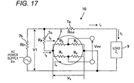
- FIGS. 16 and 17 illustrate the measurement principle.
- FIG. 16 is an illustrative diagram of an outline of the power measurement device, and
- FIG. 17 is a diagram of an equivalent circuit thereof.
- the magnetic field sensor used in this example is an element that converts a change in the external magnetic field into an electric signal, which patterns a ferromagnetic thin film 5 as a magnetic field detection film, and allows current to flow in a pattern of the magnetic field detection film to convert a change in the external magnetic field into an electric signal as a voltage change.
- the ferromagnetic thin film can be regarded as a resistor bridge including R 1 , R 2 , R 3 , and R 4 .
- the power measurement device can be designed so that resistance change rate ⁇ R 1 /R 1 is proportional to I 1 , and the voltage Vb applied to the ferromagnetic thin film is proportional to I 2 , the output Vmr is proportional to a product of I 1 and I 2 . That is, the output Vmr is a signal component proportional to the electric power.
- Vmr is (DC term) + (2 ⁇ term).
- the output Vmr appears as a ⁇ term, but its component is irrelevant to the electric power. More precisely, since the output Vmr becomes a larger value as the unbalance is larger, the degree of unbalance and the electric power component can be separated from each other.
- the electric power can be extracted directly with extraction of the term of the DC component which is the first term.
- the magnetic field sensor used in the power measurement device according to the present invention is described in the first embodiment, and therefore its description will be omitted below.
- FIG. 18 illustrates an illustrative view of the power measurement device
- FIG. 19 illustrates a cross-sectional view thereof
- FIG. 20 illustrates the output of the power measurement device.
- the power measurement device includes a magnetic field sensor 10 having a ferromagnetic thin film that is arranged in parallel to a primary conductor into which AC current flows, a feeder that is connected to the primary conductor, and has an input and output terminal that supplies element current to the ferromagnetic thin film through a resistor, and a detector that detects outputs from ends of the ferromagnetic thin film, and a DC component extractor 50 that extracts a DC component from an output of the detector.
- the feeder of the magnetic field sensor 10 is connected to an AC power supply 8 through a resistor 9 as a load.
- the DC component extractor 50 connected to the detector includes an amplifier 20, an A/D converter 30, and a CPU 40.
- the power measurement device includes the magnetic field sensor 10 that is mounted on a circuit board 1 that is a printed wiring board through a wiring pattern 3P, the amplifier 20 formed of chip parts connected to the wiring pattern 3P on the printed wiring board by soldering, the A/D converter 30, and the CPU 40 connected to each other.
- Reference numeral 2 denotes an insulating film.
- the magnetic field sensor is formed on the circuit board 1 together with the DC component extractor 50, a surface A surrounded by the ferromagnetic thin film of the magnetic field sensor and an input wire of the amplifier 20 does not intersect with a magnetic flux developed by the primary conductor current I 1 .
- the power measurement device can be thinned and downsized.
- the output thus obtained is illustrated in FIG. 20 .
- the electric power can be directly obtained by obtaining a DC component from the output Vmr.
- the signal component proportional to the electric power is extracted paying attention to a fact that the linear characteristic can be obtained with no bias magnetic field, by the aid of the planar hall effect that is a phenomenon in which the electric resistance value of the magnetic material is changed according to the angle formed between the current and the magnification within the ferromagnetic material.
- the DC component is extracted from the output of the detector by the DC component extractor. For that reason, the extracted waveform is current ⁇ voltage ⁇ power factor component, and therefore the electric power, and the electric power can be measured directly from the waveform without multiplication. Therefore, the power detection can be realized with ease and high precision.
- the ferromagnetic thin film is formed so that the magnetic resistance is symmetric about the direction of the element current.
- the signal can be most efficiently extracted when the configuration is symmetric about the output extraction point.
- the magnetic resistance is symmetric about the direction of the element current, the maximum value of the output Vmr can be largely taken, and an S/N ratio as the system is improved. Therefore, according to the above configuration, the electric power can be measured with high precision.
- the ferromagnetic thin film is formed so that the magnetization direction matches the direction of the element current from the viewpoint of the high sensitivity.
- the planar hall effect that is, the magnetoresistive effect (phenomenon that the resistance value is changed by the magnetic field) occurs in the ferromagnetic thin film.
- FIG. 21 A relationship of the current I 2 vector, the direction of the spontaneous magnetization, that is, a magnetic field H due to the primary conductor, and the combined magnetic flux density vector B MO is illustrated in FIG. 21 . From this figure, the direction of the spontaneous magnetization is held in parallel to the direction of the element current I 2 as illustrated in FIGS.
- FIGS. 21 (a) and 21(b) whereby the output (absolute value) becomes equal between the maximum value of positive and the minimum value of negative in the magnetic field direction due to the primary conductor, and a dynamic range can be maximized.
- Lower stages of FIGS. 21 (a) and 21(b) are illustrative views illustrating the generation of combined magnetization of upper stages.
- the direction of the spontaneous magnetization is held in parallel to the direction of the element current I 2 as illustrated in FIGS. 21 (c) to 21(d) , because any one of the maximum value of positive and the minimum value absolute value) of negative becomes smaller, the dynamic range of the sensor is narrowed.
- the dynamic range by a bold line in the figure in the element output and the magnetic field intensity due to the primary conductor. Because the dynamic range is defined by smaller one of the positive side and the negative side of the element output, when the element current vector I 2 is held in parallel to the spontaneous magnetization, the positive side and the negative side become equal to each other, and therefore the overall dynamic range can be most effectively obtained.
- the signal component proportional to the electric power is extracted paying attention to a fact that the linear characteristic can be obtained with no bias magnetic field, by the aid of the planar hall effect that is a phenomenon in which the electric resistance value of the magnetic material is changed according to the angle formed between the current and the magnification within the ferromagnetic material.
- the DC component is extracted from the output of the detector by the DC component extractor. For that reason, the extracted waveform is current ⁇ voltage ⁇ power factor component, and therefore the electric power, and the electric power can be measured directly from the waveform without multiplication. Therefore, the power detection can be realized with ease and high precision.
- the detector in the power measurement device, it is desirable that the detector is formed in the direction perpendicular to the direction of the element current as illustrated in illustrative views of FIGS. 23 to 24 .
- FIG. 24(a) illustrates the detector when the external magnetic field vector H is zero
- FIG. 24(b) illustrates the detector when the external magnetic field vector H has an angle of ⁇ /4.
- Vmr becomes a maximum value, and therefore the signal can be most efficiently extracted when the configuration is symmetric about the output extraction point.
- the DC component extractor 50 includes an integrator that integrates the output value every 1/f periods when the commercial frequency is f.
- Vmr is a common multiple of (DC component + Commercial frequency)
- the output value for one cycle when the electric power of the power measurement device is extracted as the output is illustrated in FIG. 25 , if the output value is integrated during the cycle of the commercial frequency, plus and minus of the AC component are offset with each other, and only the DC component can be extracted. Since the DC component can be obtained on the cycle basis, and is suited for fast operation, this configuration is excellent in transient response. Also, when the output value is integrated in a cycle, an unnecessary primary term can be dropped, and a harmonic component of the electric power can be also extracted.
- the detector of the magnetic field sensor 10 is connected with a zero-cross point detector 60 and a cycle determination unit 70, and a cycle of the output is detected by the cycle determination unit 70 on the basis of an output of the zero-cross point detector.
- the cycle is determined by the cycle determination unit 70 according to the output of the zero-cross point detector 60, and a drive timing of the DC component extractor 50 is determined according to the cycle.
- the other configurations are identical with those in the above fourth embodiment, and therefore their description will be omitted. According to this configuration, since a system frequency is always varied, the system voltage is used with the highest precision for the purpose of precisely measuring the cycle. A portion where the voltage signal is supplied to the substrate for the element current I 2 is branched, thereby enabling the cycle to be detected from the voltage signal without newly providing an external voltage signal line.
- the detector of the magnetic field sensor is connected in parallel to a capacitor 80.
- the other configurations are identical with those in the above fourth embodiment, and therefore their description will be omitted. According to this configuration, since the DC component can be extracted in a shorter period than the cycle by smoothing the Vmr signal by the capacitor, the power value can be obtained at a high speed, and the DC component can be detected with a simple circuit configuration.
- the magnetic field sensor is configured by chip parts, and mounted on the printed wiring board configuring the circuit board.
- the pattern of the ferromagnetic thin film 3 is formed directly on the printed wiring board 1 configuring the circuit board, and a conductor pattern configuring the feeder and the detector is formed in the same process as that of the wiring pattern, and integrated together.
- the amplifier, the A/D converter, and the CPU are configured by the chip parts.
- processing circuits are integrated on a silicon substrate, and the magnetic field sensor, and the magnetic field sensor is formed through an insulating film to provide a monolithic element. According to this configuration, the power measurement device can be more thinned and downsized.
- the magnetic field sensor described in the second and third embodiments may be used in the power measurement device described in the fourth to seventh embodiments.
- the magnetic field sensor and the processing circuits can be integrated by the substrate to further enable thinning and downsizing.
- the magnetic field sensor may include a magnetic thin film formed on the substrate, a feeder having an input and output terminal that supplies the element current to the magnetic thin film, and a detection electrode unit that detects outputs from both ends of the magnetic thin film, and the wiring pattern may be configured by the same conductor layer as that of the feeder and the detection electrode unit. According to this configuration, because the pattern of the magnetic thin film has only to be formed in addition to the configuration of the normal circuit board, the power measurement device can be extremely easily formed.
- the magnetic thin film may be formed so that the magnetic resistance is symmetric about the direction of the element current. According to this configuration, because the magnetic thin film is formed so that the magnetic resistance is symmetric about the direction of the element current, the maximum value of the output Vmr can be largely taken, and the S/N ratio as the system is improved.
- a capacitor connected in parallel to the detector may be provided. According to this configuration, since the DC component can be extracted in a shorter period than the cycle by smoothing the Vmr signal by the capacitor, the power value can be obtained at a high speed, and the DC component can be detected with a simple circuit configuration.
- a power measurement method including the steps of supplying element current to a pattern of a magnetic thin film so that a magnetic resistance is symmetric about a direction of the element current by using the power measurement device, and extracting a DC component of an output generated by supply of the element current as electric power information.
- the magnetic field sensor may include a magnetic thin film, a feeder having an input and output terminal that supplies element current to the magnetic thin film, and a detector that detects a voltage across the magnetic thin film (between ends thereof) in a direction perpendicular to a direction of the element current, in which the magnetic thin film is formed so that the magnetic resistance is symmetric about the direction of the element current.
- the output extraction direction of the magnetic thin film is perpendicular to the element current direction, and the magnetic resistance is symmetric about the direction of the element current.
- the element current is supplied to the pattern of the magnetic thin film so that the magnetic resistance is symmetric about the direction of the element current, and the voltage across the magnetic thin film (between ends thereof) is detected in the direction perpendicular to the supply direction of the element current to measure the magnetic field intensity.
- the output extraction direction of the magnetic thin film is perpendicular to the element current direction, and the magnetic resistance is symmetric about the direction of the element current.
- the present invention is based on Japanese Patent Application Nos. 2009-195103 and 2009-195104 filed on August 26, 2009 , and content thereof is incorporated herein by reference.
- the magnetic field sensor of the present invention since the magnetic field sensor can be detected with high precision, the magnetic field sensor can be applied to a current sensor or an electric power sensor. Also, according to the power measurement device of the present invention, the accurate power measurement can be conducted even in a load where the power factor is not 1, or a harmonic current is included, and as compared with the conventional power measurement device using a current sensor such as a rectifier, the downsizing and the low costs can be performed. Therefore, the power measurement device according to the present invention is applicable to various power saving tools.
Applications Claiming Priority (3)
| Application Number | Priority Date | Filing Date | Title |
|---|---|---|---|
| JP2009195104A JP5620076B2 (ja) | 2009-08-26 | 2009-08-26 | 電力計測装置 |
| JP2009195103A JP5620075B2 (ja) | 2009-08-26 | 2009-08-26 | 磁界センサおよびこれを用いた磁界測定方法 |
| PCT/JP2010/064532 WO2011024923A1 (ja) | 2009-08-26 | 2010-08-26 | 磁界センサ、これを用いた磁界測定方法、電力計測装置および電力計測方法 |
Publications (2)
| Publication Number | Publication Date |
|---|---|
| EP2461174A1 true EP2461174A1 (de) | 2012-06-06 |
| EP2461174A4 EP2461174A4 (de) | 2015-11-04 |
Family
ID=43628022
Family Applications (1)
| Application Number | Title | Priority Date | Filing Date |
|---|---|---|---|
| EP10811972.8A Withdrawn EP2461174A4 (de) | 2009-08-26 | 2010-08-26 | Magnetfeldsensor und magnetfeldmessverfahren, strommessvorrichtung und strommessverfahren damit |
Country Status (6)
| Country | Link |
|---|---|
| US (1) | US20120229131A1 (de) |
| EP (1) | EP2461174A4 (de) |
| KR (1) | KR101314365B1 (de) |
| CN (1) | CN102656471B (de) |
| TW (1) | TWI480566B (de) |
| WO (1) | WO2011024923A1 (de) |
Families Citing this family (20)
| Publication number | Priority date | Publication date | Assignee | Title |
|---|---|---|---|---|
| KR101831800B1 (ko) | 2011-02-01 | 2018-02-23 | 가부시키가이샤 Sirc | 전력계측장치 |
| EP2811311B1 (de) | 2012-01-31 | 2018-08-29 | Osaka City University | Batteriesystem und ladungs-/entladungsmessungsvorrichtung |
| TWI431301B (zh) | 2012-03-05 | 2014-03-21 | Ind Tech Res Inst | 應用穿隧式磁電阻器之磁場感測方法及磁場感測裝置 |
| JP5979413B2 (ja) | 2012-03-27 | 2016-08-24 | 公立大学法人大阪市立大学 | 電力計測装置 |
| US9081041B2 (en) * | 2012-04-04 | 2015-07-14 | Allegro Microsystems, Llc | High accuracy differential current sensor for applications like ground fault interrupters |
| US8896295B2 (en) | 2012-04-04 | 2014-11-25 | Allegro Microsystems, Llc | Magnetic field sensor having multiple sensing elements and a programmable misalignment adjustment device for misalignment detection and correction in current sensing and other applications |
| US9007054B2 (en) | 2012-04-04 | 2015-04-14 | Allegro Microsystems, Llc | Angle sensor with misalignment detection and correction |
| JP6083690B2 (ja) | 2012-05-11 | 2017-02-22 | 公立大学法人大阪市立大学 | 力率計測装置 |
| US10048298B2 (en) | 2012-11-29 | 2018-08-14 | Sirc Co., Ltd | Thin-film sensor type electrical power measurement device |
| TWI494581B (zh) * | 2013-01-15 | 2015-08-01 | Ind Tech Res Inst | 基於磁場特徵之方位測定方法與系統 |
| US20140210460A1 (en) * | 2013-01-30 | 2014-07-31 | Hampden Kuhns | Contactless electric meter reading devices |
| TWI619280B (zh) | 2014-04-01 | 2018-03-21 | 友達光電股份有限公司 | 感測元件 |
| CN107078209B (zh) * | 2014-10-21 | 2019-03-26 | 旭化成微电子株式会社 | 霍尔元件 |
| US10145906B2 (en) * | 2015-12-17 | 2018-12-04 | Analog Devices Global | Devices, systems and methods including magnetic structures |
| JP6868963B2 (ja) * | 2016-03-15 | 2021-05-12 | エイブリック株式会社 | 磁気センサおよびその製造方法 |
| US10067201B2 (en) * | 2016-04-14 | 2018-09-04 | Texas Instruments Incorporated | Wiring layout to reduce magnetic field |
| US10591515B2 (en) * | 2016-11-11 | 2020-03-17 | Fluke Corporation | Non-contact current measurement system |
| CN108732408B (zh) * | 2018-04-24 | 2023-11-07 | 厦门理工学院 | 一种基于磁化膜的应变式电流传感器 |
| CN109100565A (zh) * | 2018-07-05 | 2018-12-28 | 国网重庆市电力公司电力科学研究院 | 一种基于巨磁阻传感器的功率计设计方法及系统 |
| CN115219962A (zh) * | 2022-06-29 | 2022-10-21 | 珠海多创科技有限公司 | 一种功率测量装置、测量设备及功率测量方法 |
Family Cites Families (11)
| Publication number | Priority date | Publication date | Assignee | Title |
|---|---|---|---|---|
| US4504787A (en) * | 1982-04-05 | 1985-03-12 | Honeywell Inc. | Electronic watthour meter |
| JPH02120677A (ja) * | 1988-10-31 | 1990-05-08 | Fujitsu Ltd | 位相差検出装置 |
| JPH07249808A (ja) * | 1994-03-08 | 1995-09-26 | Jeco Co Ltd | 磁電変換素子 |
| JPH08242027A (ja) * | 1995-03-03 | 1996-09-17 | Mitsubishi Electric Corp | 磁気抵抗素子回路 |
| US6075437A (en) * | 1998-03-09 | 2000-06-13 | General Motors Corporation | In-plane magnetoresistance bridge |
| JP3587678B2 (ja) | 1998-03-20 | 2004-11-10 | Tdk株式会社 | 磁界センサ |
| JP3544141B2 (ja) * | 1998-05-13 | 2004-07-21 | 三菱電機株式会社 | 磁気検出素子および磁気検出装置 |
| JP2004279321A (ja) * | 2003-03-18 | 2004-10-07 | Sanyo Electric Co Ltd | 電力測定装置、逆潮流検出装置及び系統連系発電装置 |
| JP2008003072A (ja) * | 2006-05-23 | 2008-01-10 | Alps Electric Co Ltd | 薄膜磁気抵抗素子及び薄膜磁気センサ |
| EP2091137B1 (de) | 2008-02-18 | 2014-06-25 | Siemens Aktiengesellschaft | Primärteil und lineare elektrische Maschine mit Kraftwelligkeitsausgleich |
| EP2091138A1 (de) | 2008-02-18 | 2009-08-19 | Siemens Aktiengesellschaft | Primärteil und lineare elektrische Maschine mit Kraftwelligkeitsausgleich |
-
2010
- 2010-08-26 TW TW099128624A patent/TWI480566B/zh not_active IP Right Cessation
- 2010-08-26 KR KR1020127004915A patent/KR101314365B1/ko not_active IP Right Cessation
- 2010-08-26 CN CN201080038072.5A patent/CN102656471B/zh not_active Expired - Fee Related
- 2010-08-26 WO PCT/JP2010/064532 patent/WO2011024923A1/ja active Application Filing
- 2010-08-26 US US13/392,352 patent/US20120229131A1/en active Granted
- 2010-08-26 EP EP10811972.8A patent/EP2461174A4/de not_active Withdrawn
Non-Patent Citations (1)
| Title |
|---|
| See references of WO2011024923A1 * |
Also Published As
| Publication number | Publication date |
|---|---|
| KR20120047975A (ko) | 2012-05-14 |
| TWI480566B (zh) | 2015-04-11 |
| US20120229131A1 (en) | 2012-09-13 |
| EP2461174A4 (de) | 2015-11-04 |
| TW201133015A (en) | 2011-10-01 |
| CN102656471A (zh) | 2012-09-05 |
| WO2011024923A1 (ja) | 2011-03-03 |
| KR101314365B1 (ko) | 2013-10-04 |
| CN102656471B (zh) | 2015-04-01 |
Similar Documents
| Publication | Publication Date | Title |
|---|---|---|
| EP2461174A1 (de) | Magnetfeldsensor und magnetfeldmessverfahren, strommessvorrichtung und strommessverfahren damit | |
| JP5620076B2 (ja) | 電力計測装置 | |
| US10353020B2 (en) | Manufacturing method for integrated multilayer magnetoresistive sensor | |
| US8779756B2 (en) | Current sensor | |
| CN101587174B (zh) | 磁传感器 | |
| US7495624B2 (en) | Apparatus for detection of the gradient of a magnetic field, and a method for production of the apparatus | |
| US6717403B2 (en) | Method and system for improving the efficiency of the set and offset straps on a magnetic sensor | |
| JP6420821B2 (ja) | プッシュプル式フリップチップハーフブリッジ磁気抵抗スイッチ | |
| US10739165B2 (en) | Magnetic field sensor | |
| JPWO2011155527A1 (ja) | フラックスゲートセンサおよびそれを利用した電子方位計ならびに電流計 | |
| JP2011149827A (ja) | 通電情報計測装置 | |
| JP6460372B2 (ja) | 磁気センサ及びその製造方法、並びにそれを用いた計測機器 | |
| Chen et al. | A power sensor tag with interference reduction for electricity monitoring of two-wire household appliances | |
| Chen et al. | A flexible inductive coil tag for household two-wire current sensing applications | |
| JP2012150007A (ja) | 電力計測装置 | |
| TWI444627B (zh) | 電力測量裝置以及電力測量方法 | |
| US11747303B2 (en) | Magnetic sensor and inspection device | |
| EP4182707A1 (de) | Integrierter stromsensor mit magnetflusskonzentratoren | |
| JP5620075B2 (ja) | 磁界センサおよびこれを用いた磁界測定方法 | |
| JP5793682B2 (ja) | 電力計測装置 | |
| JP5793681B2 (ja) | 電力計測装置 | |
| JPH054037U (ja) | 電流検知センサ | |
| WO2011155526A1 (ja) | フラックスゲートセンサおよびそれを利用した電子方位計ならびに電流計 | |
| Zia et al. | Planar Magnetometers | |
| JPH054038U (ja) | 電流検出素子 |
Legal Events
| Date | Code | Title | Description |
|---|---|---|---|
| PUAI | Public reference made under article 153(3) epc to a published international application that has entered the european phase |
Free format text: ORIGINAL CODE: 0009012 |
|
| 17P | Request for examination filed |
Effective date: 20120301 |
|
| AK | Designated contracting states |
Kind code of ref document: A1 Designated state(s): AL AT BE BG CH CY CZ DE DK EE ES FI FR GB GR HR HU IE IS IT LI LT LU LV MC MK MT NL NO PL PT RO SE SI SK SM TR |
|
| DAX | Request for extension of the european patent (deleted) | ||
| RAP1 | Party data changed (applicant data changed or rights of an application transferred) |
Owner name: PANASONIC INTELLECTUAL PROPERTY MANAGEMENT CO., LT |
|
| RIC1 | Information provided on ipc code assigned before grant |
Ipc: G01R 21/08 20060101ALI20150512BHEP Ipc: H01L 43/08 20060101ALI20150512BHEP Ipc: G01R 33/09 20060101AFI20150512BHEP |
|
| RA4 | Supplementary search report drawn up and despatched (corrected) |
Effective date: 20151002 |
|
| RIC1 | Information provided on ipc code assigned before grant |
Ipc: G01R 33/09 20060101AFI20150928BHEP Ipc: H01L 43/08 20060101ALI20150928BHEP Ipc: G01R 21/08 20060101ALI20150928BHEP Ipc: H01L 43/06 20060101ALN20150928BHEP |
|
| 17Q | First examination report despatched |
Effective date: 20160729 |
|
| STAA | Information on the status of an ep patent application or granted ep patent |
Free format text: STATUS: EXAMINATION IS IN PROGRESS |
|
| GRAP | Despatch of communication of intention to grant a patent |
Free format text: ORIGINAL CODE: EPIDOSNIGR1 |
|
| STAA | Information on the status of an ep patent application or granted ep patent |
Free format text: STATUS: GRANT OF PATENT IS INTENDED |
|
| RIC1 | Information provided on ipc code assigned before grant |
Ipc: H01L 43/08 20060101ALI20170201BHEP Ipc: G01R 21/08 20060101ALI20170201BHEP Ipc: H01L 43/06 20060101ALN20170201BHEP Ipc: G01R 33/09 20060101AFI20170201BHEP |
|
| INTG | Intention to grant announced |
Effective date: 20170224 |
|
| STAA | Information on the status of an ep patent application or granted ep patent |
Free format text: STATUS: THE APPLICATION IS DEEMED TO BE WITHDRAWN |
|
| 18D | Application deemed to be withdrawn |
Effective date: 20170707 |