EP2461133A1 - Dispositif d'affichage de carte - Google Patents
Dispositif d'affichage de carte Download PDFInfo
- Publication number
- EP2461133A1 EP2461133A1 EP10804349A EP10804349A EP2461133A1 EP 2461133 A1 EP2461133 A1 EP 2461133A1 EP 10804349 A EP10804349 A EP 10804349A EP 10804349 A EP10804349 A EP 10804349A EP 2461133 A1 EP2461133 A1 EP 2461133A1
- Authority
- EP
- European Patent Office
- Prior art keywords
- map
- display
- icon
- point
- interest
- Prior art date
- Legal status (The legal status is an assumption and is not a legal conclusion. Google has not performed a legal analysis and makes no representation as to the accuracy of the status listed.)
- Withdrawn
Links
Images


Classifications
-
- G—PHYSICS
- G09—EDUCATION; CRYPTOGRAPHY; DISPLAY; ADVERTISING; SEALS
- G09B—EDUCATIONAL OR DEMONSTRATION APPLIANCES; APPLIANCES FOR TEACHING, OR COMMUNICATING WITH, THE BLIND, DEAF OR MUTE; MODELS; PLANETARIA; GLOBES; MAPS; DIAGRAMS
- G09B29/00—Maps; Plans; Charts; Diagrams, e.g. route diagram
- G09B29/10—Map spot or coordinate position indicators; Map reading aids
- G09B29/106—Map spot or coordinate position indicators; Map reading aids using electronic means
-
- G—PHYSICS
- G01—MEASURING; TESTING
- G01C—MEASURING DISTANCES, LEVELS OR BEARINGS; SURVEYING; NAVIGATION; GYROSCOPIC INSTRUMENTS; PHOTOGRAMMETRY OR VIDEOGRAMMETRY
- G01C21/00—Navigation; Navigational instruments not provided for in groups G01C1/00 - G01C19/00
- G01C21/26—Navigation; Navigational instruments not provided for in groups G01C1/00 - G01C19/00 specially adapted for navigation in a road network
- G01C21/34—Route searching; Route guidance
- G01C21/36—Input/output arrangements for on-board computers
- G01C21/3605—Destination input or retrieval
- G01C21/3614—Destination input or retrieval through interaction with a road map, e.g. selecting a POI icon on a road map
-
- G—PHYSICS
- G01—MEASURING; TESTING
- G01C—MEASURING DISTANCES, LEVELS OR BEARINGS; SURVEYING; NAVIGATION; GYROSCOPIC INSTRUMENTS; PHOTOGRAMMETRY OR VIDEOGRAMMETRY
- G01C21/00—Navigation; Navigational instruments not provided for in groups G01C1/00 - G01C19/00
- G01C21/26—Navigation; Navigational instruments not provided for in groups G01C1/00 - G01C19/00 specially adapted for navigation in a road network
- G01C21/34—Route searching; Route guidance
- G01C21/36—Input/output arrangements for on-board computers
- G01C21/3664—Details of the user input interface, e.g. buttons, knobs or sliders, including those provided on a touch screen; remote controllers; input using gestures
-
- G—PHYSICS
- G01—MEASURING; TESTING
- G01C—MEASURING DISTANCES, LEVELS OR BEARINGS; SURVEYING; NAVIGATION; GYROSCOPIC INSTRUMENTS; PHOTOGRAMMETRY OR VIDEOGRAMMETRY
- G01C21/00—Navigation; Navigational instruments not provided for in groups G01C1/00 - G01C19/00
- G01C21/26—Navigation; Navigational instruments not provided for in groups G01C1/00 - G01C19/00 specially adapted for navigation in a road network
- G01C21/34—Route searching; Route guidance
- G01C21/36—Input/output arrangements for on-board computers
- G01C21/3667—Display of a road map
- G01C21/367—Details, e.g. road map scale, orientation, zooming, illumination, level of detail, scrolling of road map or positioning of current position marker
-
- G—PHYSICS
- G01—MEASURING; TESTING
- G01C—MEASURING DISTANCES, LEVELS OR BEARINGS; SURVEYING; NAVIGATION; GYROSCOPIC INSTRUMENTS; PHOTOGRAMMETRY OR VIDEOGRAMMETRY
- G01C21/00—Navigation; Navigational instruments not provided for in groups G01C1/00 - G01C19/00
- G01C21/26—Navigation; Navigational instruments not provided for in groups G01C1/00 - G01C19/00 specially adapted for navigation in a road network
- G01C21/34—Route searching; Route guidance
- G01C21/36—Input/output arrangements for on-board computers
- G01C21/3679—Retrieval, searching and output of POI information, e.g. hotels, restaurants, shops, filling stations, parking facilities
- G01C21/3682—Retrieval, searching and output of POI information, e.g. hotels, restaurants, shops, filling stations, parking facilities output of POI information on a road map
-
- G—PHYSICS
- G09—EDUCATION; CRYPTOGRAPHY; DISPLAY; ADVERTISING; SEALS
- G09B—EDUCATIONAL OR DEMONSTRATION APPLIANCES; APPLIANCES FOR TEACHING, OR COMMUNICATING WITH, THE BLIND, DEAF OR MUTE; MODELS; PLANETARIA; GLOBES; MAPS; DIAGRAMS
- G09B29/00—Maps; Plans; Charts; Diagrams, e.g. route diagram
- G09B29/003—Maps
- G09B29/006—Representation of non-cartographic information on maps, e.g. population distribution, wind direction, radiation levels, air and sea routes
Definitions
- the present invention relates to a map display device that allows a map on display to be scrolled.
- Patent Literature 1 Japanese Laid Open Patent Publication No. 2008-134504
- the map display device in the related art disclosed in patent literature 1 allows its user to search for a specific point-of-interest facility he wishes to designate as a destination by scrolling the map on display if the particular point-of-interest facility is not present within the current range of the map on display.
- the user may not know which direction the point-of-interest facility is present on the map relative to the range of the map currently on display and, in such a case, the user, not knowing which direction he should scroll the map, needs to look for the point-of-interest facility through trial and error by scrolling the map in a random direction to see if the point-of-interest facility is located in that direction.
- the map display device of the related art with a map scroll function is yet to address the issue arising in the situation outlined above, i.e., a destination point-of-interest facility search performed by the user may become an unnecessarily laborious and time-consuming task.
- an object of the present invention is to provide a map display device assuring better convenience for the user searching for a point-of-interest facility he wishes to designate as the destination by scrolling the map.
- a map display device includes: a display monitor; a map display control means for bringing up a map with an icon displayed therein at the display monitor and scrolling the map in response to a scroll instruction; an icon detecting means for detecting an icon present in a specific area beyond a range of a display screen at the display monitor; and an indicator display control means for displaying an indicator indicating a direction along which the map should be scrolled in order to bring up on display the icon detected by the icon detecting means.
- the indicator display control means may change a display mode for the indicator based upon a quantity of icons detected by the icon detecting means.
- the map display device of the first or second aspect may further include a distance calculating means for calculating a distance between a position at which the icon detected by the icon detecting means is displayed on a map and a predetermined position on the map currently on display at the display monitor.
- the indicator display control means changes a display mode for the indicator based upon the distance calculated by the distance calculating means.
- the icon detecting means may further include: a range specifying means for specifying a range for the map; and a calculating means for calculating, as the predetermined area, a difference between the range specified by the range specifying means and a map range over which the map is displayed on the display screen at the display monitor.
- the indicator display control means may change a display mode for the indicator based upon a type of icon detected by the icon detecting means.
- the present invention provides a map display device assuring better convenience for the user searching for a destination point-of-interest facility by scrolling a map.
- the navigation apparatus 1 is capable of displaying an indicator indicating a direction to an icon that can be brought up on display at a display monitor 16 by scrolling a map.
- the navigation apparatus 1 includes a control circuit 11, a ROM 12, a RAM 13, a current position detection device 14, an image memory 15, the display monitor 16, a speaker 17, an input device 18, a touch panel 19 and a disk drive 111.
- a DVD-ROM 112 having map data stored therein is loaded in the disk drive 111.
- the control circuit 11 is constituted with a microprocessor and its peripheral circuits.
- the control circuit 11 executes various types of control as it executes a control program stored in the ROM 12 by using the RAM 13 as a work area.
- the control circuit 11 executes a specific type of route search processing based upon the map data stored in the DVD-ROM 112 and brings up the route search results on display as a route at the display monitor 16.
- the current position detection device 14 detects the current location of the vehicle.
- the current position detection device 14 is constituted with a vibration gyro 14a, a vehicle speed sensor 14b, a GPS (global positioning system) sensor 14c and the like.
- the vibration gyro 14a detects the direction along which the vehicle is advancing, whereas the vehicle speed sensor 14b detects the vehicle speed.
- the GPS sensor 14c detects the current position based upon GPS signals transmitted from GPS satellites.
- the current position detection device 14 detects the current location of the vehicle by using the information detected via the devices 14a through 14c.
- the navigation apparatus 1 determines a map display range and the like, based upon the current vehicle location detected by the current position detection device 14. In addition, the navigation apparatus 1 displays a subject vehicle position mark at the current location on the map.
- image data to be displayed at the display monitor 16 are stored. These image data include road map drawing data and various types of graphics data. The image data are generated as needed based upon the map data stored in the DVD-ROM 112. The navigation apparatus 1 is able to display a map and the like at the display monitor 16 by using the image data thus generated.
- the touch panel 19 is a transparent touch switch laminated over the surface of the display monitor 16. An image brought up on display at the display monitor 16 is thus viewed through the touch panel 19.
- the touch panel 19 is depressed.
- the touch panel 19 outputs a signal corresponding to the depressed position at the touch panel 19, to a touch panel control unit 110.
- the touch panel control unit 110 then calculates the position at which the touch panel 19 has been depressed based upon the signal output from the touch panel 19 and outputs the calculation results to the control circuit 11.
- the control circuit 11 executes control so as to execute processing defined in correspondence to the specific button, menu screen option or the like having been depressed.
- the touch panel 19 is depressed and the map is scrolled so as to shift the depressed position to the center of the map.
- the disk drive 111 reads out map data from the DVD-ROM 112 loaded therein, to be used to display a map at the display monitor 16.
- the map data include map display data, route search data and the like.
- the map display data and the route search data include link information and node information related to the roads in the map data.
- the map display data include map data at a plurality of different scaling factors from wide range through detailed. The scaling factor of the map on display can be thus adjusted to one of the plurality of different levels in response to a user request. It is to be noted that map data may be read out from a recording medium other than the DVD ROM 112, such as a CD-ROM or a hard disk.
- Various types of information including a map of an area around the subject vehicle position and a menu page, are provided to the user as a screen display brought up at the display monitor 16.
- voice messages prompting the user to perform a specific type of input operation or providing route guidance to the user are output.
- the user is also able to set a destination by operating the input device 18 or the touch panel 19 in response to instructions provided on the display screen at the display monitor 16 or voice instructions output through the speaker 17.
- a route search start point is set at the current position and a route search end point is set at the destination.
- route calculation is executed to determine a route from the start point to the end point based upon a specific algorithm.
- the route thus determined is indicated on the screen display at the display monitor 16 in a display mode distinguishable from other roads by, for instance, using a different display color.
- the navigation apparatus 1 guides the vehicle along the route by indicating to the user a specific direction along which the vehicle should advance with instructions provided on the screen or with voice instructions, so that the vehicle travels along the route resulting from the search calculation.
- the processing shown in FIG. 2 is executed by the control circuit 11 based upon a program started up as the map on display at the display monitor 16 is scrolled.
- step S101 the scaling factor of the map currently on display at the display monitor 16 is detected.
- step S102 a detection range is determined in reference to the center of the map on display based upon the map scaling factor having been detected in step S101. If the map on display at the display monitor 16 is a wide range map, a wide detection range is selected, whereas if a detailed map is on display at the display monitor 16, a narrow detection range is selected. The detection range is greater than the range of the map displayed on the display screen. In this embodiment, map images with a range larger than each geographical range over which the map may be displayed at the display monitor 16 are drawn and stored in the image memory 15 in advance under control executed by the control circuit 11.
- a map scroll function is achieved for the map on display at the display monitor 16 as the address from which a map image is read from the image memory 15 to display a map at the display monitor 16 is shifted in correspondence to the extent to which the map is scrolled, i.e., as the position of the origin point is shifted.
- the larger map range over which a map image is drawn and stored in the image memory 15 corresponds to the detection range in the embodiment.
- the detection range may be determined in units of meshes, provided that the map data are managed in meshes. For instance, the mesh containing the map currently on display and various meshes surrounding the particular mesh may be designated as the detection range.
- step S103 the position of the map center is detected.
- step S104 any point-of-interest facility in correspondence to which a point-of-interest facility icon should be displayed, present within the detection range set in reference to the map center having been detected in step S103, is detected.
- a point-of-interest facility icon is displayed to indicate the presence of a specific type of point-of-interest facility on the map.
- Point-of-interest facilities may be, for instance, gasoline stations, family restaurants, convenience stores, financial institutions and parking lots.
- Point-of-interest facility icons are each designed to indicate a specific type of point-of-interest facility.
- step S105 a decision is made as to whether or not there is any point-of-interest facility, in correspondence to which a point-of-interest facility icon should be displayed, present within the detection range.
- step S 105 If there is any point-of-interest facility for which a point-of-interest facility icon should be displayed is present, an affirmative decision is made in step S 105, and the operation proceeds to step S 106. If, on the other hand, there is no point-of-interest facility for which a point-of-interest facility icon should be displayed is present in the detection range, a negative decision is made in step S 105 and the operation returns to step S101.
- step S 106 the range of the map currently on display at the display monitor 16 is calculated based upon the map center position and the map scaling factor and a decision is made as to whether or not the point-of-interest facility having been detected in step S 104 is already indicated by the corresponding point-of-interest facility icon at the display monitor 16. If the point-of-interest facility icon is already displayed, an affirmative decision is made in step S 106 and the operation returns to step S101. However, if the point-of-interest facility icon is not displayed yet, a negative decision is made in step S106 and the operation proceeds to step S 107. In step S 107, the direction of the point-of-interest facility having been detected, for which the point-of-interest facility icon is to be displayed, relative to the map center is calculated.
- Point-of-interest facility information is stored in a point-of-interest (POI) facility database.
- the point-of-interest facilities are sorted in correspondence to specific categories.
- the information stored in the database includes point-of-interest facility position information constituted with data indicating the latitude and longitude of each point-of-interest facility.
- point-of-interest facility position information constituted with data indicating the latitude and longitude of each point-of-interest facility.
- step S108 an indicator indicating the direction calculated in step S107 is superimposed on the map on display.
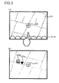
- waves 21A may be displayed as an indicator along the bottom side of a rectangular map 20, matching the direction of the point-of-interest facility for which the point-of-interest facility icon is to be displayed, among the four sides of the map 20, as shown in FIG. 3(a) .
- a cursor 22 is displayed at the center of the map 20.
- the map further on the lower side relative to the map 20 that includes point-of-interest facility icons 23a and 23b, which have not been included in the initial map 20 comes up on display, as shown in FIG. 3(b) .
- the direction of the point-of-interest facility for which the corresponding point-of-interest facility icon is displayed in this situation matches the position of the side of the display screen that intersects the line segment.
- an arrow 21B pointing downward which is the direction of the point-of-interest facility for which the point-of-interest facility icon is to be displayed, may be displayed as an indicator, as shown in FIG. 4(a) .
- an indicator other than waves or an arrow may be used, as long as the user is able to ascertain the direction of the point-of-interest facility having been detected by checking the indicator.
- step S 109 in FIG. 2 a decision is made as to whether or not the map display on the display monitor 16 is to be ended or not. If the map display is to be sustained, an affirmative decision is made in step S 109 and the operation returns to step S101. However, if the map display is to be ended, a negative decision is made in step S 109 and the indicator display processing ends.
- a point-of-interest facility icon present in a predetermined surrounding area, among point-of-interest facility icons that are not included in the scrolled map on display is detected and an indicator indicating the map scrolling direction in which the map needs to be scrolled in order to bring up the detected icon on display is displayed.
- the navigation apparatus 1 achieved in the embodiment described above allows for the following variations.
- step S 104 in FIG. 2 If a plurality of point-of-interest facilities are detected in step S 104 in FIG. 2 and the results of the calculation executed in step S 107 indicate that the point-of-interest facilities for which point-of-interest facility icons are to be displayed, are present along a plurality of directions, a plurality of indicators, each indicating a specific direction, may be displayed. For instance, point-of-interest facilities for which point-of-interest facility icons will be displayed may be present along the downward direction and along the rightward direction relative to the map center. In such a case, waves 21C and waves 21D may be displayed as indicators along the bottom side and the right side, matching the directions of the point-of-interest facilities, among the four sides of the rectangular map 20, as shown in FIG. 5(a) .
- the plurality of directions of point-of-interest facilities for which point-of-interest facility icons are to be displayed may be indicated by arrows.
- an arrow 21E indicating the downward direction among the plurality of facility directions and an arrow 21F indicating the other facility direction, i.e., the rightward direction may be displayed as indicators by overlaying them one on top of another on display, as shown in FIG. 5(b) .
- the arrow 21E, superimposed over the arrow 21F should be displayed as a semitransparent arrow so as to allow the user to see the direction indicated by the arrow 21F set under the arrow 21E.
- a downward arrow 21G and a rightward arrow 21F may be displayed separately, as shown in FIG. 5(c) .
- the indicator display mode for the indicator indicating the direction of point-of-interest facilities may be changed based upon the number of point-of-interest facilities detected in step S104 in FIG. 2 . In this case, even better convenience is assured for the user since he is able to ascertain in advance the number of icons to come up on display as he scrolls the map.
- a single wave row 21A may be displayed as shown in FIG. 3(a) .
- two wave rows 21I may be displayed as shown in FIG. 6(a) .
- three wave rows (not shown) may be displayed.
- arrows when the direction of the point-of-interest facility is indicated by arrows, if the number of point-of-interest facilities is 1 to 5, a single arrow 21B may be displayed as shown in FIG. 4(a) . And, if the number of point-of-interest facilities is 6 to 10, two arrows 21J may be displayed as shown in FIG. 6(b) . Furthermore, if the number of point-of-interest facilities is 11 or more, three arrows (not shown) may be displayed.
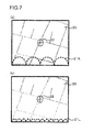
- step S 108 in FIG. 2 the distance between a specific position taken in the map currently on display, e.g., the center of the map on display, and the point-of-interest facility for which the point-of-interest facility icon is to be displayed may also be calculated so as to change the indicator display mode in correspondence to the distance thus calculated.
- the indicator display mode may be adjusted in reference to the smallest value among the values representing the distances between the center of the map on display and the individual point-of-interest facilities.
- the indicator display mode may be adjusted based upon the average of the distances between the center of the map on display and the individual point-of-interest facilities.
- the amplitude and the wavelength of waves 21K indicating the point-of-interest facility direction may be increased, as shown in FIG. 7(a) , if the distance between the map center and the point-of-interest facility is significant. If, on the other hand, the distance between the map center and the point-of-interest facility is small, the amplitude and the wavelength of waves 21L may be reduced, as shown in FIG. 7(b) . It is to be noted that only the amplitude of the waves may be increased when the distance between the map center and the point-of-interest facility is significant and only the amplitude of the waves may be reduced when the distance between the map center and the point-of-interest facility is small.
- a large arrow 21M may be displayed to indicate the point-of-interest facility direction, as shown in FIG. 8(a) , if the distance between the map center and the point-of-interest facility is significant, whereas a small arrow 21N may be displayed, as shown in FIG. 8(b) if the distance between the map center and the point-of-interest facility is small.
- step S108 in FIG. 2 the specific category assigned to the particular point-of-interest facility for which the point-of-interest facility icon is to be displayed may be detected and the indicator display mode may be adjusted based upon the category thus detected. In this case, even better user convenience is assured since the user is able to ascertain in advance whether or not the point-of-interest facility icon corresponding to a desired category can be displayed by scrolling the map.
- the user may be allowed to specify the detection range determined in step S 102 in FIG. 2 .
- the detection range determined in step S 102 in FIG. 2 .
- the user specifying the detection range may enter a specific distance from the map center via, for instance, the input device 18 and designate the range defined by the distance as the point-of-interest facility detection range.
- the indicator may be cleared even if the other icons have not yet come up on display.
- the indicator may remain on display as long as the other icons are yet to come up on display.
- the icon display mode may be turned on.
- the map indicator display processing may end.
- the embodiment may be adopted in combination with a single variation or in combination with a plurality of variations.
- the variations described above may be adopted in any conceivable combination.
Landscapes
- Engineering & Computer Science (AREA)
- Radar, Positioning & Navigation (AREA)
- Remote Sensing (AREA)
- Physics & Mathematics (AREA)
- General Physics & Mathematics (AREA)
- Automation & Control Theory (AREA)
- Theoretical Computer Science (AREA)
- Mathematical Physics (AREA)
- Business, Economics & Management (AREA)
- Educational Administration (AREA)
- Educational Technology (AREA)
- Human Computer Interaction (AREA)
- Life Sciences & Earth Sciences (AREA)
- Ecology (AREA)
- Navigation (AREA)
- Instructional Devices (AREA)
Applications Claiming Priority (2)
| Application Number | Priority Date | Filing Date | Title |
|---|---|---|---|
| JP2009176509A JP5421015B2 (ja) | 2009-07-29 | 2009-07-29 | 地図表示装置 |
| PCT/JP2010/062498 WO2011013603A1 (fr) | 2009-07-29 | 2010-07-26 | Dispositif d'affichage de carte |
Publications (2)
| Publication Number | Publication Date |
|---|---|
| EP2461133A1 true EP2461133A1 (fr) | 2012-06-06 |
| EP2461133A4 EP2461133A4 (fr) | 2015-03-04 |
Family
ID=43529258
Family Applications (1)
| Application Number | Title | Priority Date | Filing Date |
|---|---|---|---|
| EP10804349.8A Withdrawn EP2461133A4 (fr) | 2009-07-29 | 2010-07-26 | Dispositif d'affichage de carte |
Country Status (5)
| Country | Link |
|---|---|
| US (1) | US20120120115A1 (fr) |
| EP (1) | EP2461133A4 (fr) |
| JP (1) | JP5421015B2 (fr) |
| CN (2) | CN102472626B (fr) |
| WO (1) | WO2011013603A1 (fr) |
Families Citing this family (8)
| Publication number | Priority date | Publication date | Assignee | Title |
|---|---|---|---|---|
| JP5421015B2 (ja) * | 2009-07-29 | 2014-02-19 | クラリオン株式会社 | 地図表示装置 |
| US9189556B2 (en) | 2012-01-06 | 2015-11-17 | Google Inc. | System and method for displaying information local to a selected area |
| CN103063210A (zh) * | 2012-12-28 | 2013-04-24 | 上海伽利略导航有限公司 | 一种导航目的地指示方法及设备 |
| JP2014161352A (ja) * | 2013-02-21 | 2014-09-08 | Gree Inc | ゲームシステムにおけるランキングリスト表示方法及びゲームシステム、ランキングリスト表示方法プログラム |
| JP6142638B2 (ja) * | 2013-04-16 | 2017-06-07 | 株式会社デンソー | 地図差分データ配信システム、地図差分データ配信装置、及び地図差分抽出サーバ |
| US9605972B2 (en) * | 2014-06-25 | 2017-03-28 | International Business Machines Corporation | Mapping preferred locations using multiple arrows |
| DE112017001558T5 (de) * | 2016-05-30 | 2018-12-13 | Aisin Aw Co., Ltd. | Kartenanzeigesystem und Kartenanzeigeprogramm |
| US11774260B2 (en) | 2019-11-13 | 2023-10-03 | Airbnb, Inc. | Dynamic obfuscation of a mapped point of interest |
Family Cites Families (18)
| Publication number | Priority date | Publication date | Assignee | Title |
|---|---|---|---|---|
| JPH113770A (ja) * | 1997-06-11 | 1999-01-06 | Matsushita Electric Ind Co Ltd | 加熱装置 |
| JPH1137770A (ja) * | 1997-07-15 | 1999-02-12 | Nissan Motor Co Ltd | ナビゲーション装置 |
| US7389268B1 (en) * | 2000-03-02 | 2008-06-17 | Trading Technologies International, Inc. | Trading tools for electronic trading |
| JP2001297098A (ja) * | 2000-04-14 | 2001-10-26 | Denso Corp | 施設情報の登録検索システム、管理センタ、登録用端末及び検索用端末 |
| JP2002228459A (ja) * | 2001-01-30 | 2002-08-14 | Kenwood Corp | ナビゲーション装置、施設表示方法、及び、プログラム |
| JP4010183B2 (ja) * | 2002-05-17 | 2007-11-21 | ソニー株式会社 | 地図表示システム、地図表示方法、およびプログラム |
| CN2687613Y (zh) * | 2002-08-09 | 2005-03-23 | 爱信艾达株式会社 | 地图显示装置 |
| US6836723B2 (en) * | 2002-11-29 | 2004-12-28 | Alpine Electronics, Inc | Navigation method and system |
| JP4674102B2 (ja) * | 2005-03-15 | 2011-04-20 | クラリオン株式会社 | ナビゲーション装置 |
| JP2008134504A (ja) | 2006-11-29 | 2008-06-12 | Xanavi Informatics Corp | 地図表示装置 |
| RU2009130353A (ru) * | 2007-01-10 | 2011-02-20 | Томтом Интернэшнл Б.В. (Nl) | Навигационное устройство и способ |
| US7737987B2 (en) * | 2007-03-29 | 2010-06-15 | Alpine Electronics, Inc. | Display method and apparatus for adjusting contrast of map elements for navigation system |
| JP4678534B2 (ja) * | 2007-06-07 | 2011-04-27 | ソニー株式会社 | ナビゲーション装置及び地図スクロール処理方法 |
| US20090088964A1 (en) * | 2007-09-28 | 2009-04-02 | Dave Schaaf | Map scrolling method and apparatus for navigation system for selectively displaying icons |
| US8234060B2 (en) * | 2008-05-27 | 2012-07-31 | Mitsubishi Electric Corporation | Navigation device for carrying out an along-route scrolling |
| CN101319980B (zh) * | 2008-07-11 | 2010-12-22 | 天津大学 | 微牛/纳牛级超微力值测量装置及力值溯源方法 |
| US8890898B2 (en) * | 2009-01-28 | 2014-11-18 | Apple Inc. | Systems and methods for navigating a scene using deterministic movement of an electronic device |
| JP5421015B2 (ja) * | 2009-07-29 | 2014-02-19 | クラリオン株式会社 | 地図表示装置 |
-
2009
- 2009-07-29 JP JP2009176509A patent/JP5421015B2/ja not_active Expired - Fee Related
-
2010
- 2010-07-26 US US13/387,233 patent/US20120120115A1/en not_active Abandoned
- 2010-07-26 EP EP10804349.8A patent/EP2461133A4/fr not_active Withdrawn
- 2010-07-26 CN CN201080033370.5A patent/CN102472626B/zh not_active Expired - Fee Related
- 2010-07-26 WO PCT/JP2010/062498 patent/WO2011013603A1/fr active Application Filing
- 2010-07-26 CN CN201410659232.8A patent/CN104359489A/zh active Pending
Non-Patent Citations (1)
| Title |
|---|
| See references of WO2011013603A1 * |
Also Published As
| Publication number | Publication date |
|---|---|
| US20120120115A1 (en) | 2012-05-17 |
| EP2461133A4 (fr) | 2015-03-04 |
| CN104359489A (zh) | 2015-02-18 |
| CN102472626A (zh) | 2012-05-23 |
| CN102472626B (zh) | 2014-12-03 |
| JP5421015B2 (ja) | 2014-02-19 |
| JP2011027691A (ja) | 2011-02-10 |
| WO2011013603A1 (fr) | 2011-02-03 |
Similar Documents
| Publication | Publication Date | Title |
|---|---|---|
| EP2461133A1 (fr) | Dispositif d'affichage de carte | |
| US7567861B2 (en) | In-vehicle display apparatus | |
| US7869938B2 (en) | Method and apparatus for displaying simplified map image for navigation system | |
| US20110175928A1 (en) | Map Display Device and Map Display Method | |
| US20020130906A1 (en) | Point-of interest icon and point-of- interest mark display method | |
| JP2006039745A (ja) | タッチパネル式入力装置 | |
| JP2002098544A (ja) | Poiアイコン表示方法及びナビゲーション装置 | |
| JP2006329678A (ja) | 車載ナビゲーション装置 | |
| JP3898677B2 (ja) | 車両用ナビゲーション装置 | |
| JP2008180786A (ja) | ナビゲーションシステムおよびナビゲーション装置 | |
| JP4890154B2 (ja) | ナビゲーション装置 | |
| JP5328280B2 (ja) | ナビゲーション装置 | |
| JP2007128329A (ja) | 地図表示装置および施設表示方法 | |
| JP2006201072A (ja) | ナビゲーション装置 | |
| JP2002328031A (ja) | ナビゲーション装置 | |
| WO2011074638A1 (fr) | Dispositif et programme d'affichage de carte | |
| JP2007212857A (ja) | ナビゲーション装置 | |
| EP1901038B1 (fr) | Système d'affichage des cartes et système de navigation | |
| JP2012133245A (ja) | 地図表示装置、地図表示方法及びコンピュータプログラム | |
| JP2010085198A (ja) | ナビゲーション装置 | |
| JP4824611B2 (ja) | タッチパネルを備えたナビゲーション装置 | |
| JP2009288119A (ja) | ナビゲーション装置 | |
| JP3458697B2 (ja) | タッチスイッチ付きナビゲーション装置及びプログラムを記録した媒体 | |
| JP2008286585A (ja) | 車載用ナビゲーション装置 | |
| JP4885645B2 (ja) | 車載用情報端末 |
Legal Events
| Date | Code | Title | Description |
|---|---|---|---|
| PUAI | Public reference made under article 153(3) epc to a published international application that has entered the european phase |
Free format text: ORIGINAL CODE: 0009012 |
|
| 17P | Request for examination filed |
Effective date: 20120229 |
|
| AK | Designated contracting states |
Kind code of ref document: A1 Designated state(s): AL AT BE BG CH CY CZ DE DK EE ES FI FR GB GR HR HU IE IS IT LI LT LU LV MC MK MT NL NO PL PT RO SE SI SK SM TR |
|
| DAX | Request for extension of the european patent (deleted) | ||
| A4 | Supplementary search report drawn up and despatched |
Effective date: 20150129 |
|
| RIC1 | Information provided on ipc code assigned before grant |
Ipc: G01C 21/36 20060101ALI20150123BHEP Ipc: G09B 29/00 20060101ALI20150123BHEP Ipc: G09B 29/10 20060101AFI20150123BHEP |
|
| 17Q | First examination report despatched |
Effective date: 20160617 |
|
| STAA | Information on the status of an ep patent application or granted ep patent |
Free format text: STATUS: THE APPLICATION IS DEEMED TO BE WITHDRAWN |
|
| 18D | Application deemed to be withdrawn |
Effective date: 20161028 |