EP2459343B1 - Coated abrasive article and methods of ablating coated abrasive articles - Google Patents
Coated abrasive article and methods of ablating coated abrasive articles Download PDFInfo
- Publication number
- EP2459343B1 EP2459343B1 EP10806848.7A EP10806848A EP2459343B1 EP 2459343 B1 EP2459343 B1 EP 2459343B1 EP 10806848 A EP10806848 A EP 10806848A EP 2459343 B1 EP2459343 B1 EP 2459343B1
- Authority
- EP
- European Patent Office
- Prior art keywords
- coated abrasive
- abrasive article
- laser beam
- infrared laser
- component
- Prior art date
- Legal status (The legal status is an assumption and is not a legal conclusion. Google has not performed a legal analysis and makes no representation as to the accuracy of the status listed.)
- Active
Links
Images

Classifications
-
- B—PERFORMING OPERATIONS; TRANSPORTING
- B24—GRINDING; POLISHING
- B24D—TOOLS FOR GRINDING, BUFFING OR SHARPENING
- B24D11/00—Constructional features of flexible abrasive materials; Special features in the manufacture of such materials
- B24D11/04—Zonally-graded surfaces
-
- B—PERFORMING OPERATIONS; TRANSPORTING
- B24—GRINDING; POLISHING
- B24D—TOOLS FOR GRINDING, BUFFING OR SHARPENING
- B24D11/00—Constructional features of flexible abrasive materials; Special features in the manufacture of such materials
- B24D11/008—Finishing manufactured abrasive sheets, e.g. cutting, deforming
-
- B—PERFORMING OPERATIONS; TRANSPORTING
- B24—GRINDING; POLISHING
- B24D—TOOLS FOR GRINDING, BUFFING OR SHARPENING
- B24D11/00—Constructional features of flexible abrasive materials; Special features in the manufacture of such materials
- B24D11/02—Backings, e.g. foils, webs, mesh fabrics
-
- B—PERFORMING OPERATIONS; TRANSPORTING
- B41—PRINTING; LINING MACHINES; TYPEWRITERS; STAMPS
- B41M—PRINTING, DUPLICATING, MARKING, OR COPYING PROCESSES; COLOUR PRINTING
- B41M5/00—Duplicating or marking methods; Sheet materials for use therein
- B41M5/26—Thermography ; Marking by high energetic means, e.g. laser otherwise than by burning, and characterised by the material used
- B41M5/267—Marking of plastic artifacts, e.g. with laser
Definitions
- the present disclosure broadly relates to coated abrasive articles and methods of ablating them.
- Coated abrasive articles generally have an abrasive layer, comprising abrasive particles and one or more binders, secured to a major surface of a backing.
- an additional coating called a supersize, typically including a grinding aid, is included over the abrasive layer.
- the backing and/or abrasive layer may include more than one layer.
- the backing may be a laminate backing, optionally having one or more backing treatments thereon.
- the abrasive layer may include a make layer and abrasive particles embedded in the make layer and covered by a size layer which helps retain the abrasive particles.
- abrasive particles are dispersed more or less evenly throughout a polymeric binder.
- the abrasive layer is formed of shaped abrasive composites, typically having a predetermined shape (e.g., a precise shape) and arrangement on the backing.
- Such abrasives are typically prepared by coating a slurry of a corresponding binder precursor and abrasive particles on a tool having shaped cavities, laminating a backing to the tool, curing the binder precursor to form shaped abrasive composites secured to the backing, and then removing the tool.
- infrared lasers such as, for example, carbon dioxide (i.e., CO 2 ) lasers operating at a wavelength of 10.6 micrometers to convert coated abrasive roll goods into sheets and/or discs suitable for sale to consumers.
- CO 2 carbon dioxide
- adhesive-backed coated abrasives can lead to edge contamination by the adhesive resulting in difficulty in peeling off the associated release liner. Additionally, pieces of adhesive may become lodged at the interface between the abrasive layer and the workpiece, potentially creating scratches.
- the CO 2 laser produces a beam of long wave infrared (LWIR) light with the principal wavelength centered between 9.2 and 12 micrometers and tunable within this range.
- Average output power of CO 2 lasers is typically highest at 10.6 micrometers and declines when tuned to other wavelengths. Accordingly, the vast majority of commercial CO 2 laser processing is done at a single wavelength, 10.6 micrometers.
- infrared laser converting can result in hardened, raised, and/or sharp edges being formed in the abrasive layer adjacent to cuts and perforations made by the laser. These hardened edges can also adversely affect the performance of the coated abrasive.
- infrared laser ablating can result in the abrasive particles becoming covered with melted supersize thereby reducing anti-loading performance of the supersize and potentially inducing scratches on the abraded surface.
- a powdery supersize e.g., a zinc stearate supersize
- WO 2008/109211 A1 discloses abrasive articles and methods of making abrasive articles that include a supersize coating or component, such as one configured to inhibit the collection of dust and/or swarf on the abrasive coating.
- the present disclosure provides solutions to the above-mentioned deficiencies by recognizing that the problems during infrared laser ablating result from excessive heat generation relative to ablation (i.e., vaporization) of the coated abrasive article. Accordingly, the present disclosure provides methods for increasing the rate of ablation (and hence processing efficiency) while reducing the amount of associated heat generation. In general, this is accomplished by using a laser wavelength that is appropriately matched to the absorption profile of the material in the coated abrasive to be ablated.
- the method further comprises:
- the present disclosure provides a method comprising:
- the first infrared laser beam has a first average power of at least 60 watts and a first average beam intensity, wherein the first infrared laser beam is focused to a first spot where the first infrared laser beam contacts the coated abrasive article, wherein a total of all portions of the first spot having an intensity of at least half of the first average beam intensity has an area of less than or equal to 0.3 square millimeters, and wherein the first spot traces a first path on the coated abrasive article at a first rate, relative to the coated abrasive article, of at least 10 millimeters per second.
- the second infrared laser beam has a second average power of at least 60 watts and a second average beam intensity, wherein the second infrared laser beam is focused to a second spot where the second infrared laser beam contacts the coated abrasive article, wherein a total of all portions of the second spot having an intensity of at least half of the second average beam intensity has an area of less than or equal to 0.3 square millimeters, and wherein the second spot traces a second path on the coated abrasive article at a second rate, relative to the coated abrasive article, of at least 10 millimeters per second.
- the second spot traces a second path superposed on the first path.
- the second component comprises at least a portion of the at least one binder.
- the first component comprises at least a portion of the backing.
- the abrasive particles have an average particle diameter in a range of from 3 to 30 micrometers.
- the first infrared laser beam is a pulsed laser beam.
- the coated abrasive article further comprises a pressure-sensitive adhesive layer disposed on a second major surface of the backing opposite the first major surface.
- the present disclosure provides a coated abrasive article comprising: an abrasive layer secured to a backing, wherein the abrasive layer comprises abrasive particles secured by at least one binder to a first major surface of the backing; and a supersize disposed on at least a portion of the abrasive layer, wherein the coated abrasive article has a melt flow zone adjacent to an edge of the coated abrasive article, wherein the melt flow zone has a maximum width of less than 100 micrometers, and wherein the melt flow zone has a maximum height of less than 40 micrometers.
- the melt flow zone has a maximum width of less than 80 micrometers, and the melt flow zone has a maximum height of less than 15 micrometers.
- the abrasive layer comprises make and size layers.
- the abrasive layer comprises a plurality of shaped abrasive composites.
- the melt flow zone is caused by an infrared laser beam.
- coated abrasive articles ablated according to the present disclosure have little or no problem with adhesive residue as is often seen using conventional laser converting methods as practiced in the coated abrasives art. Further, coated abrasive articles ablated according to the present disclosure generally exhibit reduced adverse scratches caused by hardened residue near edges of the coated abrasive article as is also often seen using conventional laser ablating methods as practiced in the coated abrasives art.
- Coated abrasive articles generally comprise abrasive particles secured by at least one binder to a first major surface of a backing.
- the abrasive particles are secured to the backing by a combination of make and size layers.
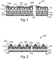
- exemplary coated abrasive article 100 comprises backing 110.
- Abrasive layer 114 is secured to first major surface 115 of backing 110, and comprises make coat 116 in which abrasive particles 118 are embedded and size coat 117 which overlays make coat 116 and abrasive particles 118.
- Supersize 119 overlays size coat 117.
- Melt flow zone 130a is disposed adjacent peripheral edge 132 and melt flow zone 130b is adjacent perforation 134.
- Optional pressure-sensitive adhesive layer 160 is disposed on a second major surface 125 of backing 110 opposite first major surface 115.
- Optional release liner 170 is disposed on optional pressure-sensitive adhesive layer 160.
- the abrasive particles are dispersed throughout a binder secured to a backing.
- Such coated abrasive articles may have a desired topography imparted to the abrasive surface.
- the abrasive layer may comprise shaped abrasive composites, which in some embodiments are precisely-shaped, secured to the backing. Structured abrasive articles fall in this category.
- a coated abrasive article 200 (a structured abrasive article) has an abrasive layer 214 that comprises shaped abrasive composites 220 secured to first major surface 215 of backing 210.
- Shaped abrasive composites 220 comprise abrasive particles 218 dispersed in binder 250.
- Supersize 219 overlays abrasive layer 214.
- Melt flow zone 230a is disposed adjacent peripheral edge 232 and melt flow zone 230b is adjacent perforation 234.
- Optional pressure-sensitive adhesive layer 260 is disposed on a second major surface 225 of backing 210 opposite first major surface 215.
- Optional release liner 270 is disposed on optional pressure-sensitive adhesive layer 260.
- coated abrasive articles may have abrasive particles of practically any size, but in the case of the coated abrasive articles shown in FIG. 2 , the abrasive particles typically have small particle sizes.
- coated abrasive particles according to the present disclosure may have abrasive particles with an average particle diameter in a range of from at least 3 to 30 micrometers. In such cases, it is especially desirable to keep the height of any melt flow zone smaller than the average particle diameter of the abrasive particles and/or shaped abrasive composites, lest they have reduced abrading efficacy.
- Coated abrasive articles according to the present invention can be converted, for example, into belts, tapes, rolls, discs (including perforated discs), and/or sheets.
- two free ends of the abrasive sheet may be joined together using known methods to form a spliced belt.
- each component of the coated abrasive article will typically have a distinct infrared absorption spectrum. Accordingly, the ability of each component to absorb infrared radiation supplied by a laser will vary, possibly drastically from component to component.
- PET polyethylene terephthalate
- PET polyethylene terephthalate
- component refers to one or more adjoining elements that form a portion of a coated abrasive article; for example, a pressure-sensitive adhesive layer or a pressure-sensitive adhesive layer in combination with a release liner and a backing.
- one or more of the various components of the coated abrasive article may contain an infrared absorbing material.
- an infrared absorbing material For example, carbon black and/or another infrared absorber can be included in the adhesive layer, resins/binders, or backing to increase infrared absorption at a particular wavelength. This may be particularly useful in the case of polyethylene terephthalate (PET) polyester, polyethylene, and polypropylene.
- PET polyethylene terephthalate
- the coated abrasive article may be configured such that its constituent parts are arranged by melting temperature or by absorbance at a given infrared wavelength.
- the absorption spectrum should generally include at least some portion of the infrared spectrum in order to match the frequency of the infrared laser to an infrared absorbance band, but it need not include the entire infrared spectrum, and it may optionally contain one or more regions of the electromagnetic spectrum at shorter and/or longer wavelengths.
- Absorption spectra for a wide number of materials are known and catalogued in standard reference works.
- absorption spectra for materials not otherwise available can be readily obtained using an infrared spectrometer according to standard techniques.
- Useful infrared spectrometers include scanning and Fourier Transform Infrared (FTIR) spectrometers, and may measure absorbance by, for example, transmission and/or reflection techniques.
- FTIR Fourier Transform Infrared
- Infrared laser(s) should be chosen such that they operate at a wavelength where the component(s) of the coated abrasive article has/have an absorbance of at least 0.01 per micrometer of thickness of the components, more typically 0.1 per micrometer of thickness, or even at least one per micrometer of the components.
- the infrared laser may be chosen to operate in a range of from 9.3 to 9.6 micrometers where absorption is typically strong, while in the case of polypropylene, the infrared laser may be chosen to operate in a range of from about 10.28 to 10.3 micrometers.
- the infrared laser(s) may be tunable or fixed wavelength, and/or pulsed or continuous wave (CW).
- Examples of infrared lasers of sufficient power to ablate material include carbon dioxide (CO 2 ) lasers.
- Other lasers operating in the infrared wavelength range include, for example, solid state crystal lasers (e.g., ruby, Nd/YAG), chemical lasers, carbon monoxide laser, fiber lasers, and solid state laser diodes.
- pulsed infrared lasers e.g., including ultrafast pulsed lasers
- CO 2 lasers are the second cheapest source of infrared laser photons after diode lasers, and are substantially cheaper than ultraviolet laser alternatives.
- the infrared laser beam(s) used in practice of the present disclosure typically has an average power of at least 60 watts (W); for example 70 W, 80 W, or 90 W or more.
- W watts
- a cross-section of the infrared laser beam (i.e., spot size) at a substrate to be cut is desirably very small, typically with an area.
- the infrared laser beam may be focused to a spot (where the infrared laser beam contacts the coated abrasive article) such that a total of all portions of the spot, having an intensity of at least half of the average beam intensity, has an area of less than or equal to 0.3 square millimeters (mm 2 ), less than about 0.1 mm 2 , or even less than 0.01 mm 2 , although smaller and larger spot sizes may also be used.
- trace rates i.e., the rate at which the beam is scanned across a substrate
- mm/sec millimeters per second
- slower trace rates may also be used.
- Laser ablating of the coated abrasive article may be achieved using a single trace of a laser beam or multiple superposed traces. Multiple laser beams may be used simultaneously or sequentially. If multiple laser beams are used, they may have the same or different wavelengths.
- individual components of a coated abrasive article are sequentially removed using infrared laser beams, each tuned to an absorbance band of a respective component (e.g., the backing and the abrasive layer).
- individual components of a coated abrasive article are simultaneously removed using multiple infrared laser beams tuned to an absorbance band of separate components of the coated abrasive article (e.g., the backing and the abrasive layer). Additional infrared lasers may also be used; for example, if additional components are present. If multiple infrared laser beams are used, their traces should typically be superposed to achieve maximum benefit, although this is not a requirement.
- Absorption of the laser beam may be single-photon or multiphoton absorption. Typically, the absorption is single photon absorption.
- Infrared laser ablation may be carried out such that it does not completely penetrate the coated abrasive article, though most typically it cuts completely through. Further, Infrared laser ablation may be carried out from any direction (e.g., from the front (abrasive) surface to the back surface or in the opposite direction) of a coated abrasive article.
- typical coated abrasive articles ablated according to the present disclosure are less prone to formation of melt flow features on the exposed surface of the abrasive layer than if ablated using a CO 2 laser operating at 10.6 micrometers as is current industry practice.
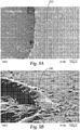
- FIGS. 3A - 4B show perforated coated abrasive discs as viewed from their abrasive surface sides.
- FIGS. 4A - 4B show results of perforating an identical coated abrasive article using the same CO 2 laser conditions except that the laser was tuned to a wavelength of 9.3 micrometers (Example 1).
- the laser beam impinged on the looped side of the abrasive disc and ablated through to the disc and exited on the abrasive layer side.
- FIGS. 3A - 3B it is apparent that the size of melt flow zone 330 formed on for Comparative Example A is substantially larger and more raised than melt flow zone 430 of Example 1 shown in corresponding FIGS. 4A - 4B .
- melt flow zones have a maximum width of less than 80 micrometers or optionally even less than 50 micrometers, and a maximum height of less than 40 micrometers, optionally less than 15 micrometers or even less than 5 micrometers.
- This may be particularly important for fine grit sizes such as, for example, those coated abrasive discs with a zinc stearate supersize and an abrasive particle size of P800 to P1500 as the abrasive particles may be smaller than raised features of the melt flow zones, leading to wild scratches.
Landscapes
- Engineering & Computer Science (AREA)
- Mechanical Engineering (AREA)
- Physics & Mathematics (AREA)
- Optics & Photonics (AREA)
- Polishing Bodies And Polishing Tools (AREA)
- Laser Beam Processing (AREA)
Applications Claiming Priority (2)
| Application Number | Priority Date | Filing Date | Title |
|---|---|---|---|
| US22909109P | 2009-07-28 | 2009-07-28 | |
| PCT/US2010/042998 WO2011017022A2 (en) | 2009-07-28 | 2010-07-23 | Coated abrasive article and methods of ablating coated abrasive articles |
Publications (3)
| Publication Number | Publication Date |
|---|---|
| EP2459343A2 EP2459343A2 (en) | 2012-06-06 |
| EP2459343A4 EP2459343A4 (en) | 2017-10-25 |
| EP2459343B1 true EP2459343B1 (en) | 2020-06-17 |
Family
ID=43544840
Family Applications (1)
| Application Number | Title | Priority Date | Filing Date |
|---|---|---|---|
| EP10806848.7A Active EP2459343B1 (en) | 2009-07-28 | 2010-07-23 | Coated abrasive article and methods of ablating coated abrasive articles |
Country Status (5)
| Country | Link |
|---|---|
| US (1) | US9033765B2 (enExample) |
| EP (1) | EP2459343B1 (enExample) |
| JP (2) | JP2013500869A (enExample) |
| CN (1) | CN102470511B (enExample) |
| WO (1) | WO2011017022A2 (enExample) |
Families Citing this family (25)
| Publication number | Priority date | Publication date | Assignee | Title |
|---|---|---|---|---|
| CN105713568B (zh) | 2010-11-01 | 2018-07-03 | 3M创新有限公司 | 用于制备成形陶瓷磨粒的激光法、成形陶瓷磨粒以及磨料制品 |
| SG191204A1 (en) | 2010-12-30 | 2013-07-31 | 3M Innovative Properties Co | Laser cutting method and articles produced therewith |
| US9674317B2 (en) * | 2011-02-10 | 2017-06-06 | Marvell World Trade Ltd. | Multi-clock PHY preamble design and detection |
| US20120322352A1 (en) * | 2011-06-20 | 2012-12-20 | 3M Innovative Properties Company | Sandpaper with laminated non-slip layer |
| EP2551057B1 (de) * | 2011-07-25 | 2016-01-06 | sia Abrasives Industries AG | Verfahren zur Herstellung eines beschichteten Schleifmittels, beschichtetes Schleifmittel und Verwendung eines beschichteten Schleifmittels |
| TW201404528A (zh) * | 2012-06-29 | 2014-02-01 | 聖高拜磨料有限公司 | 研磨物品及形成方法 |
| DE102013005139A1 (de) * | 2013-03-26 | 2014-10-02 | Fraunhofer-Gesellschaft zur Förderung der angewandten Forschung e.V. | Verfahren zum Abtragen von sprödhartem Material mittels Laserstrahlung |
| TWI589406B (zh) * | 2013-06-28 | 2017-07-01 | 聖高拜磨料有限公司 | 具有浮渣脊之研磨製品及其形成方法 |
| CN105636746B (zh) * | 2013-10-18 | 2017-10-13 | 3M创新有限公司 | 涂覆磨料制品及其制备方法 |
| US10307889B2 (en) * | 2015-03-30 | 2019-06-04 | 3M Innovative Properties Company | Coated abrasive article and method of making the same |
| JP6762024B2 (ja) * | 2016-07-28 | 2020-09-30 | 三星ダイヤモンド工業株式会社 | レーザ加工装置及びレーザ加工方法 |
| JP2018055044A (ja) * | 2016-09-30 | 2018-04-05 | 日本ゼオン株式会社 | 光学フィルムの製造方法 |
| CN109844597B (zh) * | 2016-12-20 | 2020-11-20 | 古河电气工业株式会社 | 光纤间歇带芯线的制造方法和光纤间歇带芯线 |
| USD849066S1 (en) * | 2017-12-12 | 2019-05-21 | 3M Innovative Properties Company | Coated abrasive disc |
| USD870782S1 (en) * | 2017-12-12 | 2019-12-24 | 3M Innovative Properties Company | Coated abrasive disc |
| USD862538S1 (en) * | 2017-12-12 | 2019-10-08 | 3M Innovative Properties Company | Coated abrasive disc |
| USD879164S1 (en) * | 2017-12-12 | 2020-03-24 | 3M Innovative Properties Company | Coated abrasive disc |
| USD849067S1 (en) * | 2017-12-12 | 2019-05-21 | 3M Innovative Properties Company | Coated abrasive disc |
| US11701755B2 (en) | 2017-12-20 | 2023-07-18 | 3M Innovative Properties Company | Abrasive articles including a saturant and an anti-loading size layer |
| JP6744634B2 (ja) * | 2018-02-28 | 2020-08-19 | 三星ダイヤモンド工業株式会社 | レーザ加工方法 |
| JP2018112754A (ja) * | 2018-03-22 | 2018-07-19 | 住友化学株式会社 | 樹脂フィルム、それを用いた偏光板及び樹脂フィルムの切断加工方法 |
| DE102020209520A1 (de) | 2020-07-29 | 2022-02-03 | Robert Bosch Gesellschaft mit beschränkter Haftung | Verfahren zur Behandlung eines Schleifartikels sowie Schleifartikel |
| FI130281B (en) * | 2021-11-25 | 2023-06-01 | Mirka Oy | Abrasive product |
| CN117182794A (zh) * | 2022-05-30 | 2023-12-08 | 圣戈班磨料磨具有限公司 | 具有玻璃增强部件的薄轮 |
| CN117260000A (zh) * | 2023-10-31 | 2023-12-22 | 江阴纳力新材料科技有限公司 | 一种涂层结构可控的涂碳集流体及其制备方法和二次电池 |
Family Cites Families (41)
| Publication number | Priority date | Publication date | Assignee | Title |
|---|---|---|---|---|
| CA1266569A (en) | 1984-05-09 | 1990-03-13 | Minnesota Mining And Manufacturing Company | Coated abrasive product incorporating selective mineral substitution |
| CA1266568A (en) | 1984-05-09 | 1990-03-13 | Minnesota Mining And Manufacturing Company | Coated abrasive product incorporating selective mineral substitution |
| JPH0771788B2 (ja) * | 1986-07-29 | 1995-08-02 | 三菱マテリアル株式会社 | 砥 石 |
| US4751138A (en) | 1986-08-11 | 1988-06-14 | Minnesota Mining And Manufacturing Company | Coated abrasive having radiation curable binder |
| JPH01159178A (ja) * | 1987-12-16 | 1989-06-22 | Hitachi Maxell Ltd | 研磨フィルム |
| NL8901257A (nl) * | 1989-05-19 | 1990-12-17 | Leeuwarder Papier | Werkwijze voor het aanbrengen van verzwakkingslijnen in resp. het graveren van kunststofmateriaal, in het bijzonder verpakkingsmateriaal. |
| US5378251A (en) | 1991-02-06 | 1995-01-03 | Minnesota Mining And Manufacturing Company | Abrasive articles and methods of making and using same |
| US5152917B1 (en) | 1991-02-06 | 1998-01-13 | Minnesota Mining & Mfg | Structured abrasive article |
| US5316812A (en) | 1991-12-20 | 1994-05-31 | Minnesota Mining And Manufacturing Company | Coated abrasive backing |
| CA2116686A1 (en) | 1991-12-20 | 1993-07-08 | Harold Wayne Benedict | A coated abrasive belt with an endless, seamless backing and method of preparation |
| US5256170A (en) | 1992-01-22 | 1993-10-26 | Minnesota Mining And Manufacturing Company | Coated abrasive article and method of making same |
| US5203884A (en) | 1992-06-04 | 1993-04-20 | Minnesota Mining And Manufacturing Company | Abrasive article having vanadium oxide incorporated therein |
| US5435816A (en) | 1993-01-14 | 1995-07-25 | Minnesota Mining And Manufacturing Company | Method of making an abrasive article |
| CA2115889A1 (en) | 1993-03-18 | 1994-09-19 | David E. Broberg | Coated abrasive article having diluent particles and shaped abrasive particles |
| US5436063A (en) | 1993-04-15 | 1995-07-25 | Minnesota Mining And Manufacturing Company | Coated abrasive article incorporating an energy cured hot melt make coat |
| US5441549A (en) | 1993-04-19 | 1995-08-15 | Minnesota Mining And Manufacturing Company | Abrasive articles comprising a grinding aid dispersed in a polymeric blend binder |
| RU2124978C1 (ru) | 1993-09-13 | 1999-01-20 | Миннесота Майнинг Энд Мэнюфекчуринг Компани | Абразивное изделие, способ его производства, способ его использования для чистовой обработки и рабочий инструмент для его производства |
| KR970701118A (ko) * | 1994-02-22 | 1997-03-17 | 로저 로이 템트 | 연마 물품, 이의 제조 방법 및 이를 표면 마무리용으로서 사용하는 방법(abrasive article, a method of making same, and a method of using same for finishing) |
| EP0783394B1 (en) | 1994-09-30 | 2003-05-14 | Minnesota Mining And Manufacturing Company | Coated abrasive article and method for preparing the same |
| WO1997006926A1 (en) | 1995-08-11 | 1997-02-27 | Minnesota Mining And Manufacturing Company | Method of making a coated abrasive article having multiple abrasive natures |
| JPH11513620A (ja) | 1995-10-20 | 1999-11-24 | ミネソタ・マイニング・アンド・マニュファクチャリング・カンパニー | 無機金属オルトリン酸塩を含有する研磨物品 |
| CN1092095C (zh) | 1996-05-08 | 2002-10-09 | 明尼苏达矿业和制造公司 | 包括抗填充成分的磨料制品 |
| US5766277A (en) | 1996-09-20 | 1998-06-16 | Minnesota Mining And Manufacturing Company | Coated abrasive article and method of making same |
| US5851247A (en) | 1997-02-24 | 1998-12-22 | Minnesota Mining & Manufacturing Company | Structured abrasive article adapted to abrade a mild steel workpiece |
| US5942015A (en) | 1997-09-16 | 1999-08-24 | 3M Innovative Properties Company | Abrasive slurries and abrasive articles comprising multiple abrasive particle grades |
| DE19745294A1 (de) | 1997-10-14 | 1999-04-15 | Biotronik Mess & Therapieg | Verfahren zur Herstellung feinstrukturierter medizintechnischer Implantate |
| US6039775A (en) * | 1997-11-03 | 2000-03-21 | 3M Innovative Properties Company | Abrasive article containing a grinding aid and method of making the same |
| US6139594A (en) | 1998-04-13 | 2000-10-31 | 3M Innovative Properties Company | Abrasive article with tie coat and method |
| US6228133B1 (en) | 1998-05-01 | 2001-05-08 | 3M Innovative Properties Company | Abrasive articles having abrasive layer bond system derived from solid, dry-coated binder precursor particles having a fusible, radiation curable component |
| US6077601A (en) | 1998-05-01 | 2000-06-20 | 3M Innovative Properties Company | Coated abrasive article |
| JP2000246473A (ja) * | 1999-02-23 | 2000-09-12 | Nippon Micro Coating Kk | レーザースリット装置及び方法及びレーザースリット用シート |
| US6821189B1 (en) * | 2000-10-13 | 2004-11-23 | 3M Innovative Properties Company | Abrasive article comprising a structured diamond-like carbon coating and method of using same to mechanically treat a substrate |
| US7344574B2 (en) | 2005-06-27 | 2008-03-18 | 3M Innovative Properties Company | Coated abrasive article, and method of making and using the same |
| US7344575B2 (en) | 2005-06-27 | 2008-03-18 | 3M Innovative Properties Company | Composition, treated backing, and abrasive articles containing the same |
| US7169017B1 (en) * | 2005-08-10 | 2007-01-30 | Rohm And Haas Electronic Materials Cmp Holdings, Inc. | Polishing pad having a window with reduced surface roughness |
| US7497768B2 (en) | 2005-08-11 | 2009-03-03 | 3M Innovative Properties Company | Flexible abrasive article and method of making |
| US7393269B2 (en) | 2005-09-16 | 2008-07-01 | 3M Innovative Properties Company | Abrasive filter assembly and methods of making same |
| US8080072B2 (en) * | 2007-03-05 | 2011-12-20 | 3M Innovative Properties Company | Abrasive article with supersize coating, and methods |
| US7959694B2 (en) * | 2007-03-05 | 2011-06-14 | 3M Innovative Properties Company | Laser cut abrasive article, and methods |
| FI20075533A7 (fi) | 2007-07-10 | 2009-01-11 | Oy Kwh Mirka Ab | Hiomatuote ja menetelmä tämän valmistamiseksi |
| JP7071788B2 (ja) * | 2019-05-13 | 2022-05-19 | 東芝三菱電機産業システム株式会社 | 盗難防止器具 |
-
2010
- 2010-07-23 WO PCT/US2010/042998 patent/WO2011017022A2/en not_active Ceased
- 2010-07-23 EP EP10806848.7A patent/EP2459343B1/en active Active
- 2010-07-23 US US13/377,743 patent/US9033765B2/en active Active
- 2010-07-23 CN CN201080031474.2A patent/CN102470511B/zh active Active
- 2010-07-23 JP JP2012522914A patent/JP2013500869A/ja active Pending
-
2015
- 2015-03-03 JP JP2015041382A patent/JP5855300B2/ja active Active
Non-Patent Citations (1)
| Title |
|---|
| None * |
Also Published As
| Publication number | Publication date |
|---|---|
| EP2459343A4 (en) | 2017-10-25 |
| JP2015128819A (ja) | 2015-07-16 |
| JP2013500869A (ja) | 2013-01-10 |
| WO2011017022A2 (en) | 2011-02-10 |
| CN102470511B (zh) | 2014-12-24 |
| EP2459343A2 (en) | 2012-06-06 |
| US20120122383A1 (en) | 2012-05-17 |
| CN102470511A (zh) | 2012-05-23 |
| US9033765B2 (en) | 2015-05-19 |
| JP5855300B2 (ja) | 2016-02-09 |
| WO2011017022A3 (en) | 2011-04-28 |
Similar Documents
| Publication | Publication Date | Title |
|---|---|---|
| EP2459343B1 (en) | Coated abrasive article and methods of ablating coated abrasive articles | |
| EP2129491B1 (en) | Abrasive article with supersi ze coating, and manufacturing method | |
| US7959694B2 (en) | Laser cut abrasive article, and methods | |
| US7134943B2 (en) | Wafer processing method | |
| Hosokawa et al. | Laser dressing of metal bonded diamond wheel | |
| US20130212952A1 (en) | Laser Method for Making Shaped Ceramic Abrasive Particles, Shaped Ceramic Abrasive Particles, and Abrasive Articles | |
| US20120055097A1 (en) | Abrasive Articles and Methods of Forming | |
| KR101849430B1 (ko) | 레이저 다이싱용 보조 시트 | |
| RU2528299C2 (ru) | Абразивное изделие, имеющее линию пониженного сопротивления | |
| JP2019533631A (ja) | シート状ガラス基体のレーザに基づく加工のための基体処理ステーション | |
| AU2017202868A1 (en) | Abrasive article having a dross ridge and method of forming same | |
| CN105636746A (zh) | 涂覆磨料制品及其制备方法 | |
| US9895787B2 (en) | Methods for modifying and adding features on grinding wheel surfaces | |
| US12576482B2 (en) | Porous coated abrasive article and method of making the same | |
| TWI606984B (zh) | 玻璃工件的切割方法 | |
| CN110491821A (zh) | 芯片贴装膜 |
Legal Events
| Date | Code | Title | Description |
|---|---|---|---|
| PUAI | Public reference made under article 153(3) epc to a published international application that has entered the european phase |
Free format text: ORIGINAL CODE: 0009012 |
|
| 17P | Request for examination filed |
Effective date: 20120117 |
|
| AK | Designated contracting states |
Kind code of ref document: A2 Designated state(s): AL AT BE BG CH CY CZ DE DK EE ES FI FR GB GR HR HU IE IS IT LI LT LU LV MC MK MT NL NO PL PT RO SE SI SK SM TR |
|
| DAX | Request for extension of the european patent (deleted) | ||
| A4 | Supplementary search report drawn up and despatched |
Effective date: 20170927 |
|
| RIC1 | Information provided on ipc code assigned before grant |
Ipc: B24D 11/04 20060101ALI20170921BHEP Ipc: C09K 3/14 20060101ALI20170921BHEP Ipc: B24D 18/00 20060101ALI20170921BHEP Ipc: B24D 3/02 20060101AFI20170921BHEP Ipc: B24D 11/00 20060101ALI20170921BHEP Ipc: B24D 11/02 20060101ALI20170921BHEP |
|
| STAA | Information on the status of an ep patent application or granted ep patent |
Free format text: STATUS: EXAMINATION IS IN PROGRESS |
|
| 17Q | First examination report despatched |
Effective date: 20190401 |
|
| GRAP | Despatch of communication of intention to grant a patent |
Free format text: ORIGINAL CODE: EPIDOSNIGR1 |
|
| STAA | Information on the status of an ep patent application or granted ep patent |
Free format text: STATUS: GRANT OF PATENT IS INTENDED |
|
| INTG | Intention to grant announced |
Effective date: 20200115 |
|
| GRAS | Grant fee paid |
Free format text: ORIGINAL CODE: EPIDOSNIGR3 |
|
| GRAA | (expected) grant |
Free format text: ORIGINAL CODE: 0009210 |
|
| STAA | Information on the status of an ep patent application or granted ep patent |
Free format text: STATUS: THE PATENT HAS BEEN GRANTED |
|
| AK | Designated contracting states |
Kind code of ref document: B1 Designated state(s): AL AT BE BG CH CY CZ DE DK EE ES FI FR GB GR HR HU IE IS IT LI LT LU LV MC MK MT NL NO PL PT RO SE SI SK SM TR |
|
| REG | Reference to a national code |
Ref country code: GB Ref legal event code: FG4D |
|
| REG | Reference to a national code |
Ref country code: CH Ref legal event code: EP |
|
| REG | Reference to a national code |
Ref country code: IE Ref legal event code: FG4D |
|
| REG | Reference to a national code |
Ref country code: DE Ref legal event code: R096 Ref document number: 602010064655 Country of ref document: DE |
|
| REG | Reference to a national code |
Ref country code: AT Ref legal event code: REF Ref document number: 1280740 Country of ref document: AT Kind code of ref document: T Effective date: 20200715 |
|
| REG | Reference to a national code |
Ref country code: FI Ref legal event code: FGE |
|
| PG25 | Lapsed in a contracting state [announced via postgrant information from national office to epo] |
Ref country code: NO Free format text: LAPSE BECAUSE OF FAILURE TO SUBMIT A TRANSLATION OF THE DESCRIPTION OR TO PAY THE FEE WITHIN THE PRESCRIBED TIME-LIMIT Effective date: 20200917 Ref country code: GR Free format text: LAPSE BECAUSE OF FAILURE TO SUBMIT A TRANSLATION OF THE DESCRIPTION OR TO PAY THE FEE WITHIN THE PRESCRIBED TIME-LIMIT Effective date: 20200918 Ref country code: SE Free format text: LAPSE BECAUSE OF FAILURE TO SUBMIT A TRANSLATION OF THE DESCRIPTION OR TO PAY THE FEE WITHIN THE PRESCRIBED TIME-LIMIT Effective date: 20200617 Ref country code: LT Free format text: LAPSE BECAUSE OF FAILURE TO SUBMIT A TRANSLATION OF THE DESCRIPTION OR TO PAY THE FEE WITHIN THE PRESCRIBED TIME-LIMIT Effective date: 20200617 |
|
| REG | Reference to a national code |
Ref country code: LT Ref legal event code: MG4D |
|
| REG | Reference to a national code |
Ref country code: NL Ref legal event code: MP Effective date: 20200617 |
|
| PG25 | Lapsed in a contracting state [announced via postgrant information from national office to epo] |
Ref country code: BG Free format text: LAPSE BECAUSE OF FAILURE TO SUBMIT A TRANSLATION OF THE DESCRIPTION OR TO PAY THE FEE WITHIN THE PRESCRIBED TIME-LIMIT Effective date: 20200917 Ref country code: LV Free format text: LAPSE BECAUSE OF FAILURE TO SUBMIT A TRANSLATION OF THE DESCRIPTION OR TO PAY THE FEE WITHIN THE PRESCRIBED TIME-LIMIT Effective date: 20200617 Ref country code: HR Free format text: LAPSE BECAUSE OF FAILURE TO SUBMIT A TRANSLATION OF THE DESCRIPTION OR TO PAY THE FEE WITHIN THE PRESCRIBED TIME-LIMIT Effective date: 20200617 |
|
| REG | Reference to a national code |
Ref country code: AT Ref legal event code: MK05 Ref document number: 1280740 Country of ref document: AT Kind code of ref document: T Effective date: 20200617 |
|
| PG25 | Lapsed in a contracting state [announced via postgrant information from national office to epo] |
Ref country code: NL Free format text: LAPSE BECAUSE OF FAILURE TO SUBMIT A TRANSLATION OF THE DESCRIPTION OR TO PAY THE FEE WITHIN THE PRESCRIBED TIME-LIMIT Effective date: 20200617 Ref country code: AL Free format text: LAPSE BECAUSE OF FAILURE TO SUBMIT A TRANSLATION OF THE DESCRIPTION OR TO PAY THE FEE WITHIN THE PRESCRIBED TIME-LIMIT Effective date: 20200617 |
|
| PG25 | Lapsed in a contracting state [announced via postgrant information from national office to epo] |
Ref country code: AT Free format text: LAPSE BECAUSE OF FAILURE TO SUBMIT A TRANSLATION OF THE DESCRIPTION OR TO PAY THE FEE WITHIN THE PRESCRIBED TIME-LIMIT Effective date: 20200617 Ref country code: SM Free format text: LAPSE BECAUSE OF FAILURE TO SUBMIT A TRANSLATION OF THE DESCRIPTION OR TO PAY THE FEE WITHIN THE PRESCRIBED TIME-LIMIT Effective date: 20200617 Ref country code: EE Free format text: LAPSE BECAUSE OF FAILURE TO SUBMIT A TRANSLATION OF THE DESCRIPTION OR TO PAY THE FEE WITHIN THE PRESCRIBED TIME-LIMIT Effective date: 20200617 Ref country code: RO Free format text: LAPSE BECAUSE OF FAILURE TO SUBMIT A TRANSLATION OF THE DESCRIPTION OR TO PAY THE FEE WITHIN THE PRESCRIBED TIME-LIMIT Effective date: 20200617 Ref country code: IT Free format text: LAPSE BECAUSE OF FAILURE TO SUBMIT A TRANSLATION OF THE DESCRIPTION OR TO PAY THE FEE WITHIN THE PRESCRIBED TIME-LIMIT Effective date: 20200617 Ref country code: CZ Free format text: LAPSE BECAUSE OF FAILURE TO SUBMIT A TRANSLATION OF THE DESCRIPTION OR TO PAY THE FEE WITHIN THE PRESCRIBED TIME-LIMIT Effective date: 20200617 Ref country code: PT Free format text: LAPSE BECAUSE OF FAILURE TO SUBMIT A TRANSLATION OF THE DESCRIPTION OR TO PAY THE FEE WITHIN THE PRESCRIBED TIME-LIMIT Effective date: 20201019 Ref country code: ES Free format text: LAPSE BECAUSE OF FAILURE TO SUBMIT A TRANSLATION OF THE DESCRIPTION OR TO PAY THE FEE WITHIN THE PRESCRIBED TIME-LIMIT Effective date: 20200617 |
|
| PG25 | Lapsed in a contracting state [announced via postgrant information from national office to epo] |
Ref country code: PL Free format text: LAPSE BECAUSE OF FAILURE TO SUBMIT A TRANSLATION OF THE DESCRIPTION OR TO PAY THE FEE WITHIN THE PRESCRIBED TIME-LIMIT Effective date: 20200617 Ref country code: SK Free format text: LAPSE BECAUSE OF FAILURE TO SUBMIT A TRANSLATION OF THE DESCRIPTION OR TO PAY THE FEE WITHIN THE PRESCRIBED TIME-LIMIT Effective date: 20200617 Ref country code: IS Free format text: LAPSE BECAUSE OF FAILURE TO SUBMIT A TRANSLATION OF THE DESCRIPTION OR TO PAY THE FEE WITHIN THE PRESCRIBED TIME-LIMIT Effective date: 20201017 |
|
| REG | Reference to a national code |
Ref country code: CH Ref legal event code: PL |
|
| REG | Reference to a national code |
Ref country code: DE Ref legal event code: R097 Ref document number: 602010064655 Country of ref document: DE |
|
| PG25 | Lapsed in a contracting state [announced via postgrant information from national office to epo] |
Ref country code: MC Free format text: LAPSE BECAUSE OF FAILURE TO SUBMIT A TRANSLATION OF THE DESCRIPTION OR TO PAY THE FEE WITHIN THE PRESCRIBED TIME-LIMIT Effective date: 20200617 |
|
| PLBE | No opposition filed within time limit |
Free format text: ORIGINAL CODE: 0009261 |
|
| STAA | Information on the status of an ep patent application or granted ep patent |
Free format text: STATUS: NO OPPOSITION FILED WITHIN TIME LIMIT |
|
| REG | Reference to a national code |
Ref country code: BE Ref legal event code: MM Effective date: 20200731 |
|
| PG25 | Lapsed in a contracting state [announced via postgrant information from national office to epo] |
Ref country code: LI Free format text: LAPSE BECAUSE OF NON-PAYMENT OF DUE FEES Effective date: 20200731 Ref country code: DK Free format text: LAPSE BECAUSE OF FAILURE TO SUBMIT A TRANSLATION OF THE DESCRIPTION OR TO PAY THE FEE WITHIN THE PRESCRIBED TIME-LIMIT Effective date: 20200617 Ref country code: CH Free format text: LAPSE BECAUSE OF NON-PAYMENT OF DUE FEES Effective date: 20200731 Ref country code: LU Free format text: LAPSE BECAUSE OF NON-PAYMENT OF DUE FEES Effective date: 20200723 |
|
| 26N | No opposition filed |
Effective date: 20210318 |
|
| GBPC | Gb: european patent ceased through non-payment of renewal fee |
Effective date: 20200917 |
|
| PG25 | Lapsed in a contracting state [announced via postgrant information from national office to epo] |
Ref country code: BE Free format text: LAPSE BECAUSE OF NON-PAYMENT OF DUE FEES Effective date: 20200731 Ref country code: SI Free format text: LAPSE BECAUSE OF FAILURE TO SUBMIT A TRANSLATION OF THE DESCRIPTION OR TO PAY THE FEE WITHIN THE PRESCRIBED TIME-LIMIT Effective date: 20200617 |
|
| PG25 | Lapsed in a contracting state [announced via postgrant information from national office to epo] |
Ref country code: GB Free format text: LAPSE BECAUSE OF NON-PAYMENT OF DUE FEES Effective date: 20200917 Ref country code: IE Free format text: LAPSE BECAUSE OF NON-PAYMENT OF DUE FEES Effective date: 20200723 |
|
| PG25 | Lapsed in a contracting state [announced via postgrant information from national office to epo] |
Ref country code: TR Free format text: LAPSE BECAUSE OF FAILURE TO SUBMIT A TRANSLATION OF THE DESCRIPTION OR TO PAY THE FEE WITHIN THE PRESCRIBED TIME-LIMIT Effective date: 20200617 Ref country code: MT Free format text: LAPSE BECAUSE OF FAILURE TO SUBMIT A TRANSLATION OF THE DESCRIPTION OR TO PAY THE FEE WITHIN THE PRESCRIBED TIME-LIMIT Effective date: 20200617 Ref country code: CY Free format text: LAPSE BECAUSE OF FAILURE TO SUBMIT A TRANSLATION OF THE DESCRIPTION OR TO PAY THE FEE WITHIN THE PRESCRIBED TIME-LIMIT Effective date: 20200617 |
|
| PG25 | Lapsed in a contracting state [announced via postgrant information from national office to epo] |
Ref country code: MK Free format text: LAPSE BECAUSE OF FAILURE TO SUBMIT A TRANSLATION OF THE DESCRIPTION OR TO PAY THE FEE WITHIN THE PRESCRIBED TIME-LIMIT Effective date: 20200617 |
|
| P01 | Opt-out of the competence of the unified patent court (upc) registered |
Effective date: 20230530 |
|
| PGFP | Annual fee paid to national office [announced via postgrant information from national office to epo] |
Ref country code: FI Payment date: 20250620 Year of fee payment: 16 |
|
| PGFP | Annual fee paid to national office [announced via postgrant information from national office to epo] |
Ref country code: FR Payment date: 20250620 Year of fee payment: 16 |
|
| PGFP | Annual fee paid to national office [announced via postgrant information from national office to epo] |
Ref country code: DE Payment date: 20250620 Year of fee payment: 16 |