EP2459325B1 - Hochdruckreinigungsgerät - Google Patents
Hochdruckreinigungsgerät Download PDFInfo
- Publication number
- EP2459325B1 EP2459325B1 EP09781114.5A EP09781114A EP2459325B1 EP 2459325 B1 EP2459325 B1 EP 2459325B1 EP 09781114 A EP09781114 A EP 09781114A EP 2459325 B1 EP2459325 B1 EP 2459325B1
- Authority
- EP
- European Patent Office
- Prior art keywords
- connection element
- pressure cleaning
- cleaning apparatus
- pressure
- accordance
- Prior art date
- Legal status (The legal status is an assumption and is not a legal conclusion. Google has not performed a legal analysis and makes no representation as to the accuracy of the status listed.)
- Active
Links
Images

Classifications
-
- B—PERFORMING OPERATIONS; TRANSPORTING
- B08—CLEANING
- B08B—CLEANING IN GENERAL; PREVENTION OF FOULING IN GENERAL
- B08B3/00—Cleaning by methods involving the use or presence of liquid or steam
- B08B3/02—Cleaning by the force of jets or sprays
- B08B3/026—Cleaning by making use of hand-held spray guns; Fluid preparations therefor
-
- B—PERFORMING OPERATIONS; TRANSPORTING
- B08—CLEANING
- B08B—CLEANING IN GENERAL; PREVENTION OF FOULING IN GENERAL
- B08B2203/00—Details of cleaning machines or methods involving the use or presence of liquid or steam
- B08B2203/02—Details of machines or methods for cleaning by the force of jets or sprays
- B08B2203/0247—Hose joints, e.g. quick joints, rotating joints
Definitions
- the invention relates to a high-pressure cleaning device, comprising a motor-driven pump unit, a first connection element for releasable connection to a liquid supply line which is connected to the suction side of the pump unit, and a second connection element for releasable connection to a high-pressure line which is connected to the pressure side of the pump unit ,
- the first connection element in an upright operating and rest position of the high-pressure cleaning device on a footprint, in an upwardly facing away from the footprint direction is aligned.
- the pump unit for example, to achieve the lowest possible center of gravity is located deep on the high-pressure cleaner near the footprint. According deep, the first connection element and the second connection element are positioned on the high-pressure cleaner to form the pump unit leading and outgoing from this liquid lines as short as possible. The deep positioning of the connection elements makes their connection with the liquid supply line and the high-pressure line difficult.
- the EP 0 813 917 A2 describes a high-pressure cleaning device with a motor-driven pump unit having connecting elements for connection to a liquid supply line and with a high-pressure line.
- the high-pressure cleaning device can assume two different operating positions. In a standing operating position, the connection elements are oriented at a shallow angle rising from the footprint for the high-pressure cleaner. In a horizontal operating position are the connection elements oriented at a steep angle rising from the footprint.
- a high-pressure cleaning device of the type mentioned is, for example, in the US 3,575,348 described.
- the high-pressure cleaner has obliquely upward from a footprint facing connecting elements for connecting a liquid supply line and a high-pressure line.
- Object of the present invention is to develop a high-pressure cleaning device of the type mentioned so that it is manageable in a user-friendly way.
- the first and optionally the second connection element are oriented away from the installation surface facing upwards.
- the first and optionally the second connection element for a user on the one hand in a simpler manner recognizable than in a generic high-pressure cleaner.
- the user is facilitated the connection of the liquid supply line to the first connection element and optionally the high-pressure line to the second connection element. From above, the user can arrange and connect the liquid supply line in a user-friendly manner to the first connection element and optionally arrange and connect the high-pressure line to the second connection element.
- the first connection element is connected to the pump unit via a suction line.
- the second connection element is connected to the pump unit via a dispensing line.
- the first and optionally the second connection element is designed as part of the suction line or as part of the discharge line.
- the use of a suction line and optionally a discharge line makes it possible to form the first and optionally the second connection element no larger than required.
- a positioning of the first and optionally of the second connection element on the high-pressure cleaning device can be selected, in which the user can connect the liquid supply line and optionally the high-pressure line to the high-pressure cleaning device in a user-friendly manner.
- first connection element and optionally the second connection element do not protrude laterally beyond a base area of the high-pressure cleaning device. This reduces the risk that a user inadvertently abuts the first and optionally the second connection element and as a result damages the high-pressure cleaning device.
- the suction line extends at least with a section adjoining the first connection element in a direction pointing downwards onto the installation surface.
- the delivery line extends at least with a section adjoining the second connection element in a direction pointing downwards onto the installation surface.
- the first and optionally the second connection element can be positioned at a greater distance from the installation surface, so that a user is facilitated the connection of the liquid supply line or the high-pressure line. It is advantageous if the first connection element and / or the second connection element extend in an obliquely upward direction away from the footprint.
- the oblique course of the first and / or second connection element allows a more user-friendly connection of the liquid supply line and / or the high-pressure line to the high-pressure cleaner with a natural, unbowed posture by the user.
- the first and / or the second connection element may be inclined relative to a plane defined by the installation surface, for example by approximately 40 ° to 80 °, and preferably by 50 ° to 70 °.
- first connection element and the second connection element are aligned at approximately the same angle relative to the installation surface. This facilitates the connection of the liquid supply line and the high-pressure line in addition, and it can be achieved in particular that a user does not have to change his posture when connecting them in the high-pressure cleaning device or only insignificantly. In addition, a pleasing appearance of the high-pressure cleaner can be achieved in this way.
- first connection element and the second connection element are oriented approximately parallel to one another, because this facilitates the connection of the liquid supply line and the high-pressure line to the high-pressure cleaning device and gives it an even more pleasing appearance.
- the first connection element and / or the second connection element preferably have a spacing of approximately 15 cm or more from the installation surface. This can ensure that between the first and / or the second connection element and the footprint sufficient space for the user remains to connect the liquid supply line or the high pressure line. In one embodiment of such a high-pressure cleaning device in practice, it has proven to be advantageous if the first and / or the second connection element have a distance of about 15 cm to 45 cm and preferably 25 cm to 40 cm to the footprint.
- first connection element and the second connection element have approximately the same distance to the installation surface, so that a user is enabled to connect the liquid supply line and the high-pressure line with substantially the same body posture. Moreover, such a high-pressure cleaner is given a more pleasing appearance.
- first connection element and the second connection element are spaced apart from each other by approximately 5 cm to 20 cm.
- this gives the possibility that a user can connect the adjoining connection elements with the liquid supply line and the high-pressure line without significantly changing his posture.
- a sufficient gap between the two connecting elements is present, so that the user sufficient freedom of movement remains to connect the liquid supply line and the high-pressure line to the high-pressure cleaner.
- the distance between the two connection elements may be in particular approximately 10 cm to 15 cm.
- a user is further facilitated the connection of the liquid supply line to the first connection element and the high-pressure line to the second connection element when the first connection element and the second connection element are arranged on the same side of the high-pressure cleaner. Without significant change in his posture, the In this case, users establish a connection of the respective line to the respective connection element.
- first connection element and / or the second connection element have a distance to a lateral boundary of the base of about 5 cm to 15 cm in projection on the footprint.
- the danger is reducible that a user unintentionally abuts on the first and / or on the second connection element and thereby damages the high-pressure cleaning device.
- Such holding a hose on the high-pressure cleaner proves to be advantageous, for example, during a break in work. Also in this case can thus be ensured that the risk of damage to the high pressure cleaning device can be reduced by accidental bumping on the liquid supply line and / or the high pressure line.
- the suction line and / or the discharge line are integrally formed.
- the suction line may be formed from a one-piece plastic molded part.
- the high-pressure cleaning device is designed as a heatable high-pressure cleaning device with a heat exchanger for heating the liquid in the discharge line.
- a heat exchanger for heating the liquid in the discharge line.
- the heat exchanger which is operable by means of a fossil fuel, for example, can from the pump unit heated under high pressure liquid are heated in the discharge line and in this way a better cleaning effect can be achieved.
- the high-pressure cleaning device comprises a drum for receiving a high-pressure hose forming the high-pressure line.
- the high-pressure hose can be at least partially wound up and stored in this way space-saving and user-friendly.
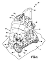
- FIG. 1 A first preferred embodiment of a high-pressure cleaning device according to the invention is in FIG. 1 shown in perspective and there occupied by the reference numeral 10. It has an approximately parallelepiped housing 12 composed of several parts, with a rear side 14, a front side 16, a left side 18, a right side 20, an upper side 22 and a lower side 24. At the rear side 14 facing areas of the left side 18 and the right side 20 are mounted on the bottom 24, two wheels 26 and 28 on the housing 12.
- the housing 12 forms a known per se and not shown in the drawing supporting element in the form of a support foot.
- the high-pressure cleaning device 10 on a footprint 1 in the in FIG. 1 shown upright position stand.
- This upright position can take the high-pressure cleaner 10 both in operation, in which a liquid supply line and a high-pressure line to the high-pressure cleaner 10 are connected in the manner described below, as well as at times when the high-pressure cleaner is not in operation.
- At the in FIG. 1 illustrated upright position of the high pressure cleaning device 10 is therefore an operating position and a rest position thereof.
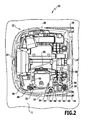
- a pump unit in the form of a high-pressure pump 32 is held ( FIG. 2 ).
- the high-pressure pump 32 is arranged on a side facing the left side 18 approximately in the middle between the rear side 14 and the front side 16 on the housing base 30. It is motor-driven by a not shown in the drawing electric motor of the high-pressure cleaner 10 in a known manner to set a high-pressure cleaning device 10 supplied liquid, in particular water, to increase the cleaning effect under pressure.
- a suction line 34 is connected to the suction side, for example, by flanging.
- the suction line 34 may be formed in one piece and in particular consist of a plastic molded part. Starting from the high-pressure pump 32, it rises relative to the footprint 1 at an angle of approximately 60 ° obliquely upward and is partially embedded in a trough-shaped recess 40 which is formed by the housing base 30 on the left side 18 above the left wheel 26 , A high-pressure pump 32 facing away from the end 36 of the suction line 34 is thus positioned in the region of a recess 42 by an offset of the left side 18 of the housing 12 is formed in the direction of the center of the high-pressure cleaner 10 above the left wheel 26.
- the suction line 34 forms a first connection element 44 in the form of a connecting piece 46, to which a not shown in the drawing and per se known liquid supply line to the high-pressure cleaner 10 can be detachably connected.
- the liquid supply line is typically designed as a flexible hose line.
- Liquid which is supplied to the high-pressure pump 32 via the connecting piece 46 and the suction line 34, can leave this via a pump outlet 48.
- a discharge line 50 is connected to the high-pressure pump 32, which initially extends parallel to the top of the housing base 30 with a first portion 52 near the pump outlet 48.
- the first section 52 is followed by a second section, which in a known and not shown manner turns a in FIG. 1 forms only slightly beginning heat exchanger 54 can be heated with the pressurized liquid in the discharge line 50 to increase the cleaning effect.
- the discharge line 50 Downstream of the heat exchanger 54, the discharge line 50 comprises a third section 56, which in turn extends approximately parallel to the top of the housing base 30. At its end 58 facing away from the high-pressure pump 32, however, the delivery line 50 rises with its third section 56 upwards at an angle of approximately 60 ° to the set-up surface 1. In this case, it is partially embedded in a recess 60 which is formed in the vicinity of the recess 40 above the left wheel 26 from the housing base 30. Near the rear side 14, the discharge line 50 emerges from the housing 12 from, wherein the end 58 is also disposed in the region of the recess 42 of the housing 12.
- the end 58 of the discharge line 50 is formed by a second connection element 62 in the form of a high-pressure connection 64 known per se.
- a high-pressure line can be detachably connected to the high-pressure connection 64, for example in the form of a normally used high-pressure hose ,
- the suction line 34 and the discharge line 50 extend obliquely upward in the region of their ends 36 and 58, respectively, in a direction pointing away from the installation surface 1 for the high-pressure cleaning device 10.
- the connection piece 46 and the high-pressure connection 64 are thus aligned in an obliquely upward direction away from the footprint 1 direction. Relative to a plane defined by the footprint 1, they occupy an angle of approximately 50 ° to 70 ° and typically 60 °. From the footprint 1, they are approximately 35 cm to 40 cm apart, and they have approximately the same distance from the footprint 1.
- the high-pressure pump 32 is located near the bottom 24 to achieve a low center of gravity, by this arrangement of the port 46 and high-pressure port 64, the user is able to detachably connect the liquid supply line and the high-pressure line to the high-pressure cleaner 10 in a user-friendly way.
- the liquid supply line and the high-pressure line can be connected in particular from above to the connecting piece 46 and the high-pressure connection 64, wherein due to their inclination relative to the vertical of the user can assume a natural posture.
- a user may connect the fluid supply line to the spud 46 and the high pressure line to the high pressure port 64 because the spud 46 and the high pressure port 64 are located close to each other on the left side 18 above the left wheel 26. They have, for example, a distance of 10 cm to 15 cm. At the same time, this distance is sufficient so that the user does not find it disturbing to connect the high-pressure line to the high-pressure port 64 when the liquid supply line is already connected to the connecting piece 46 and vice versa, because sufficient freedom of movement for the user remains.
- connection piece 46 and the high-pressure connection 64 are also used meaningfully, because there is a depression 66 formed by the housing base 30 between the recesses 40 and 60.
- an accessory for the high-pressure cleaning device 10 can be inserted, for example, a jet pipe or a nozzle, wherein the resulting due to the recess 42 space above the left wheel 26 can be exploited.
- connection piece 46 and the high-pressure connection 64 run approximately parallel to one another. This gives the high-pressure cleaner 10 on the one hand a pleasing appearance. On the other hand, it helps to avoid possible conflicts between a liquid supply line and a high-pressure line, in particular if these are each designed as flexible hose lines.
- the parallel arrangement of the connection piece 46 and the high-pressure connection 64 at a distance from one another reduces the risk of that the hose lines obstruct each other, for example, twist and / or knot.
- both the connecting piece 46 and the high-pressure port 64 do not protrude laterally beyond a base surface of the high-pressure cleaning device 10.
- they In projection onto the footprint 1, in particular, they have a distance from a lateral boundary of the base of, for example, 5 cm to 15 cm, typically about 10 cm.
- connection piece 46 and the high-pressure connection 64 reduce the risk of damage to the high-pressure cleaning device 10 even if a liquid supply line or a high-pressure line in the form of hose lines are connected to the connection piece 46 and the high-pressure connection 64.
- hose lines can be deposited, for example, in the wound state on the upper side 22 of the housing 12, wherein they are arranged starting from the connecting piece 46 or from the high-pressure connection 64 in the region of the recess 42 are.
- the hose lines do not protrude beyond the lateral boundary of the high-pressure cleaning device 10. The risk of a user inadvertently abutting the tubing is thus reduced.
- FIG. 3 A second preferred embodiment of a high-pressure cleaning device according to the invention is in FIG. 3 shown in perspective and there occupied by the reference numeral 80.
- Components and features of the high-pressure cleaning device 80 which are formed the same or equivalent to components of the high-pressure cleaning device 10, are assigned the same reference numerals. The achievable with these components and features advantages of the high-pressure cleaning device 10 can also be achieved with the high-pressure cleaner 80.
- the end of the discharge line 50 facing away from the high-pressure pump 32 is formed by a third section 82, which adjoins the second section below the heat exchanger 54, not shown in the drawing. It extends in the vertical direction and emerges from the housing 12 at the upper side 22 near the left side 18.
- the heat exchanger 54 facing away from the third portion 82 enters the housing 84 of a disposed on the top 22 hose drum 86 and forms at the end of a high pressure port.
- This is connected in a known and therefore unspecified manner with a high-pressure line 88 in the form of a high-pressure hose 90.
- the high pressure hose 90 can be wound onto the hose reel 86 and stored in this space saving and user-friendly.
- the hose reel 86 is attached to a U-shaped handling handle 92, which extends from the upper side 22 in the vertical direction and serves for tilting and for moving the high-pressure cleaning device 80.
Landscapes
- Cleaning By Liquid Or Steam (AREA)
Description
- Die Erfindung betrifft ein Hochdruckreinigungsgerät, umfassend ein motorisch antreibbares Pumpaggregat, ein erstes Anschlusselement zum lösbaren Verbinden mit einer Flüssigkeitszufuhrleitung, das mit der Saugseite des Pumpaggregats verbunden ist, sowie ein zweites Anschlusselement zum lösbaren Verbinden mit einer Hochdruckleitung, das mit der Druckseite des Pumpaggregats verbunden ist, wobei das erste Anschlusselement, in einer aufrechten Betriebs- und Ruhestellung des Hochdruckreinigungsgerätes auf einer Aufstellfläche, in einer nach oben von der Aufstellfläche weg weisenden Richtung ausgerichtet ist.
- Es sind Hochdruckreinigungsgeräte bekannt, bei denen das Pumpaggregat, beispielsweise um einen möglichst niedrig gelegenen Schwerpunkt zu erzielen, tief am Hochdruckreinigungsgerät nahe der Aufstellfläche angeordnet ist. Entsprechend tief sind das erste Anschlusselement und das zweite Anschlusselement am Hochdruckreinigungsgerät positioniert, um zum Pumpaggregat führende und von diesem abgehende Flüssigkeitsleitungen möglichst kurz auszubilden. Die tiefe Positionierung der Anschlusselemente erschwert deren Verbindung mit der Flüssigkeitszufuhrleitung und der Hochdruckleitung.
- Die
EP 0 813 917 A2 beschreibt ein Hochdruckreinigungsgerät mit einem motorisch antreibbaren Pumpaggregat, das Anschlusselemente zum Verbinden mit einer Flüssigkeitszufuhrleitung und mit einer Hochdruckleitung aufweist. Das Hochdruckreinigungsgerät kann zwei unterschiedliche Betriebsstellungen einnehmen. In einer stehenden Betriebsstellung sind die Anschlusselemente in einem flachen Winkel von der Aufstellfläche für das Hochdruckreinigungsgerät ansteigend ausgerichtet. In einer liegenden Betriebsstellung sind die Anschlusselemente unter einem steilen Winkel von der Aufstellfläche ansteigend ausgerichtet. - Ein Hochdruckreinigungsgerät der eingangs genannten Art ist beispielsweise in der
US 3,575,348 beschrieben. Das Hochdruckreinigungsgerät weist schräg nach oben von einer Aufstellfläche weg weisende Anschlusselemente zum Anschließen einer Flüssigkeitszufuhrleitung und einer Hochdruckleitung auf. - Aufgabe der vorliegenden Erfindung ist es, ein Hochdruckreinigungsgerät der eingangs genannten Art so weiterzubilden, dass es auf benutzerfreundlichere Weise handhabbar ist.
- Diese Aufgabe wird bei einem gattungsgemäßen Hochdruckreinigungsgerät erfindungsgemäß durch die Merkmale des kennzeichnenden Teils von Anspruch 1 gelöst.
- Beim erfindungsgemäßen Hochdruckreinigungsgerät sind das erste und optional das zweite Anschlusselement von der Aufstellfläche weg weisend nach oben ausgerichtet. Dadurch sind das erste und optional das zweite Anschlusselement für einen Benutzer zum Einen auf einfachere Weise erkennbar als bei einem gattungsgemäßen Hochdruckreinigungsgerät. Zum Anderen wird dem Benutzer das Anschließen der Flüssigkeitszufuhrleitung an das erste Anschlusselement und optional der Hochdruckleitung an das zweite Anschlusselement erleichtert. Von oben kann der Benutzer die Flüssigkeitszufuhrleitung auf benutzerfreundliche Weise an dem ersten Anschlusselement anordnen und mit diesem verbinden und optional die Hochdruckleitung an dem zweiten Anschlusselement anordnen und mit diesem verbinden.
- Das erste Anschlusselement ist mit dem Pumpaggregat über eine Saugleitung verbunden. Optional ist das zweite Anschlusselement mit dem Pumpaggregat über eine Abgabeleitung verbunden. Hierbei kann insbesondere vorgesehen sein, dass das erste und optional das zweite Anschlusselement als Teil der Saugleitung bzw. als Teil der Abgabeleitung ausgebildet ist. Der Einsatz einer Saugleitung und optional einer Abgabeleitung erlaubt es, das erste und optional das zweite Anschlusselement nicht größer als erforderlich auszubilden. Zugleich kann dennoch eine Positionierung des ersten und optional des zweiten Anschlusselementes am Hochdruckreinigungsgerät gewählt werden, bei der der Benutzer die Flüssigkeitszufuhrleitung und optional die Hochdruckleitung auf benutzerfreundliche Weise am Hochdruckreinigungsgerät anschließen kann.
- Günstig ist es, dass das erste Anschlusselement und optional das zweite Anschlusselement nicht seitlich über eine Grundfläche des Hochdruckreinigungsgerätes hinaus ragen. Dies verringert die Gefahr, dass ein Benutzer unbeabsichtigterweise an das erste und optional an das zweite Anschlusselement anstößt und infolgedessen das Hochdruckreinigungsgerät beschädigt.
- Die Saugleitung verläuft zumindest mit einem sich an das erste Anschlusselement anschließenden Abschnitt in einer nach unten auf die Aufstellfläche weisenden Richtung. Optional verläuft die Abgabeleitung zumindest mit einem sich an das zweite Anschlusselement anschließenden Abschnitt in einer nach unten auf die Aufstellfläche weisenden Richtung. Auf diese Weise können das erste und optional das zweite Anschlusselement in einem größeren Abstand zur Aufstellfläche positioniert werden, so dass einem Benutzer das Anschließen der Flüssigkeitszufuhrleitung bzw. der Hochdruckleitung erleichtert wird. Günstig ist es, wenn das erste Anschlusselement und/oder das zweite Anschlusselement in einer schräg nach oben von der Aufstellfläche weg weisenden Richtung verlaufen. Der schräge Verlauf des ersten und/oder zweiten Anschlusselementes ermöglicht ein benutzerfreundlicheres Anschließen der Flüssigkeitszufuhrleitung und/oder der Hochdruckleitung an das Hochdruckreinigungsgerät mit einer natürlichen, unverkrümmten Körperhaltung durch den Benutzer. Das erste und/oder das zweite Anschlusselement können relativ zu einer durch die Aufstellfläche definierten Ebene beispielsweise ungefähr um 40° bis 80° geneigt sein und bevorzugt um 50° bis 70°.
- Von Vorteil ist es, wenn das erste Anschlusselement und das zweite Anschlusselement ungefähr in demselben Winkel relativ zur Aufstellfläche ausgerichtet sind. Dies erleichtert das Anschließen der Flüssigkeitszufuhrleitung und der Hochdruckleitung zusätzlich, und es kann insbesondere erreicht werden, dass ein Benutzer seine Körperhaltung beim Anschließen derselben in das Hochdruckreinigungsgerät nicht oder nur unwesentlich ändern muss. Darüber hinaus kann auf diese Weise ein gefälliges Aussehen des Hochdruckreinigungsgerätes erzielt werden.
- Insbesondere ist es günstig, wenn das erste Anschlusselement und das zweite Anschlusselement ungefähr parallel zueinander ausgerichtet sind, denn dies erleichtert das Anschließen der Flüssigkeitszufuhrleitung und der Hochdruckleitung an das Hochdruckreinigungsgerät weiter und verleiht diesem ein noch gefälligeres Aussehen.
- Bevorzugt weisen das erste Anschlusselement und/oder das zweite Anschlusselement einen Abstand von ungefähr 15 cm oder mehr von der Aufstellfläche auf. Dadurch kann sichergestellt werden, dass zwischen dem ersten und/oder dem zweiten Anschlusselement und der Aufstellfläche hinreichend Raum für den Benutzer verbleibt, um die Flüssigkeitszufuhrleitung bzw. die Hochdruckleitung anzuschließen. Bei einer Ausgestaltung eines derartigen Hochdruckreinigungsgerätes in der Praxis hat es sich als günstig erwiesen, wenn das erste und/oder das zweite Anschlusselement einen Abstand von ungefähr 15 cm bis 45 cm und vorzugsweise 25 cm bis 40 cm zur Aufstellfläche aufweisen.
- Es kann insbesondere vorgesehen sein, dass das erste Anschlusselement und das zweite Anschlusselement ungefähr denselben Abstand zur Aufstellfläche aufweisen, so dass einem Benutzer der Anschluss der Flüssigkeitszufuhrleitung und der Hochdruckleitung mit im Wesentlichen derselben Körperhaltung ermöglicht wird. Überdies wird einem derartigen Hochdruckreinigungsgerät ein gefälligeres Aussehen verliehen.
- Günstig ist es, wenn das erste Anschlusselement und das zweite Anschlusselement voneinander ungefähr 5 cm bis 20 cm beabstandet sind. Dies gibt zum Einen die Möglichkeit, dass ein Benutzer die nahe beieinander liegenden Anschlusselemente ohne nennenswerte Änderung seiner Körperhaltung mit der Flüssigkeitszufuhrleitung und der Hochdruckleitung verbinden kann. Zum Anderen ist ein hinreichender Zwischenraum zwischen den beiden Anschlusselementen vorhanden, so dass dem Benutzer ausreichend Bewegungsfreiheit verbleibt, um die Flüssigkeitszufuhrleitung und die Hochdruckleitung an das Hochdruckreinigungsgerät anzuschließen. Der Abstand der beiden Anschlusselemente kann insbesondere ungefähr 10 cm bis 15 cm betragen.
- Einem Benutzer wird das Verbinden der Flüssigkeitszufuhrleitung mit dem ersten Anschlusselement und der Hochdruckleitung mit dem zweiten Anschlusselement weiter erleichtert, wenn das erste Anschlusselement und das zweite Anschlusselement an derselben Seite des Hochdruckreinigungsgerätes angeordnet sind. Ohne wesentliche Änderung seiner Körperhaltung kann der Benutzer in diesem Fall eine Verbindung der jeweiligen Leitung zu dem jeweiligen Anschlusselement herstellen.
- Von Vorteil ist es, wenn das erste Anschlusselement und/oder das zweite Anschlusselement in Projektion auf die Aufstellfläche einen Abstand zu einer seitlichen Begrenzung der Grundfläche von ungefähr 5 cm bis 15 cm aufweisen. Dadurch ist die Gefahr verringerbar, dass ein Benutzer unbeabsichtigterweise am ersten und/oder am zweiten Anschlusselement anstößt und dadurch das Hochdruckreinigungsgerät beschädigt. Ferner ist die Möglichkeit gegeben, auch bei Anschluss einer Flüssigkeitszufuhrleitung und/oder einer Hochdruckleitung in Form eines Schlauches am ersten bzw. am zweiten Anschlusselement diese am Hochdruckreinigungsgerät derart zu haltern, dass sie ebenfalls nicht seitlich über die Grundfläche des Hochdruckreinigungsgerätes hinaus ragen. Ein derartiges Haltern eines Schlauches am Hochdruckreinigungsgerät erweist sich beispielsweise in einer Arbeitspause als vorteilhaft. Auch in diesem Fall kann somit sichergestellt werden, dass die Gefahr einer Beschädigung des Hochdruckreinigungsgerätes durch ein unbeabsichtigtes Anstoßen an der Flüssigkeitszufuhrleitung und/oder der Hochdruckleitung verringert werden kann.
- Zur Erzielung einer einfachen Konstruktion des Hochdruckreinigungsgerätes und zur Kostenersparnis ist es von Vorteil, wenn die Saugleitung und/oder die Abgabeleitung einstückig ausgebildet sind. Insbesondere kann die Saugleitung aus einem einstückigen Kunststoffformteil ausgebildet sein.
- Bevorzugt ist das Hochdruckreinigungsgerät als beheizbares Hochdruckreinigungsgerät ausgebildet mit einem Wärmetauscher zum Erhitzen der Flüssigkeit in der Abgabeleitung. Mittels des Wärmetauschers, der zum Beispiel mittels eines fossilen Brennstoffs betreibbar ist, kann die vom Pumpaggregat unter Hochdruck gesetzte Flüssigkeit in der Abgabeleitung erhitzt werden und auf diese Weise eine bessere Reinigungswirkung erzielt werden.
- Günstig ist es, wenn das Hochdruckreinigungsgerät eine Trommel zum Aufnehmen eines die Hochdruckleitung ausbildenden Hochdruckschlauches umfasst. Auf der Trommel kann der Hochdruckschlauch zumindest teilweise aufgewickelt und auf diese Weise Platz sparend und benutzerfreundlich bevorratet werden.
- Die nachfolgende Beschreibung bevorzugter Ausführungsformen der Erfindung dient im Zusammenhang mit der Zeichnung der näheren Erläuterung der Erfindung. Es zeigen:
- Figur 1:
- eine perspektivische Ansicht einer ersten bevorzugten Ausführungsform eines erfindungsgemäßen Hochdruckreinigungsgerätes mit einem Gehäuse;
- Figur 2:
- eine Draufsicht auf einen unteren Teil des Gehäuses des Hochdruckreinigungsgerätes aus
Figur 1 und - Figur 3:
- eine perspektivische Ansicht einer zweiten bevorzugten Ausführungsform eines erfindungsgemäßen Hochdruckreinigungsgerätes.
- Eine erste bevorzugte Ausführungsform eines erfindungsgemäßen Hochdruckreinigungsgerätes ist in
Figur 1 perspektivisch dargestellt und dort insgesamt mit dem Bezugszeichen 10 belegt. Es weist ein näherungsweise quaderförmiges, aus mehreren Teilen zusammengesetztes Gehäuse 12 auf mit einer Rückseite 14, einer Vorderseite 16, einer linken Seite 18, einer rechten Seite 20, einer Oberseite 22 sowie einer Unterseite 24. An den der Rückseite 14 zugewandten Bereichen der linken Seite 18 und der rechten Seite 20 sind an der Unterseite 24 zwei Räder 26 bzw. 28 am Gehäuse 12 gelagert. - An der Unterseite 24 bildet das Gehäuse 12 ein an sich bekanntes und in der Zeichnung nicht dargestelltes Abstützelement in Form eines Stützfußes aus. Über diesen Stützfuß und die Räder 26 und 28 kann das Hochdruckreinigungsgerät 10 auf einer Aufstellfläche 1 in der in
Figur 1 gezeigten aufrechten Stellung stehen. Diese aufrechte Stellung kann das Hochdruckreinigungsgerät 10 sowohl im Betrieb einnehmen, bei dem auf nachfolgend beschriebene Weise eine Flüssigkeitszufuhrleitung und eine Hochdruckleitung an das Hochdruckreinigungsgerät 10 angeschlossen werden, als auch zu Zeiten, in denen das Hochdruckreinigungsgerät nicht in Betrieb ist. Bei der inFigur 1 dargestellten aufrechten Stellung des Hochdruckreinigungsgerätes 10 handelt es sich demnach um eine Betriebsstellung und eine Ruhestellung desselben. - Auf einem Gehäusesockel 30, der den unteren Teil des Gehäuses 12 bildet, ist ein Pumpaggregat in Form einer Hochdruckpumpe 32 gehalten (
Figur 2 ). Die Hochdruckpumpe 32 ist dabei an einem der linken Seite 18 zugewandten Bereich etwa in der Mitte zwischen der Rückseite 14 und der Vorderseite 16 auf dem Gehäusesockel 30 angeordnet. Sie ist von einem in der Zeichnung nicht dargestellten Elektromotor des Hochdruckreinigungsgerätes 10 in bekannter Weise motorisch angetrieben, um eine dem Hochdruckreinigungsgerät 10 zugeführte Flüssigkeit, insbesondere Wasser, zur Steigerung der Reinigungswirkung unter Druck zu setzen. - Um der Hochdruckpumpe 32 unter Druck zu setzende Flüssigkeit zuzuführen, ist an sie saugseitig eine Saugleitung 34 angeschlossen, beispielsweise durch Anflanschen. Die Saugleitung 34 kann einstückig ausgebildet sein und insbesondere aus einem Kunststoffformteil bestehen. Ausgehend von der Hochdruckpumpe 32 steigt sie relativ zur Aufstellfläche 1 in einem Winkel von ungefähr 60° schräg nach oben an und ist dabei teilweise in eine wannenförmige Vertiefung 40 eingebettet, die durch den Gehäusesockel 30 an der linken Seite 18 oberhalb des linken Rades 26 gebildet wird. Ein der Hochdruckpumpe 32 abgewandtes Ende 36 der Saugleitung 34 ist damit im Bereich einer Ausnehmung 42 positioniert, die durch einen Versatz der linken Seite 18 des Gehäuses 12 in Richtung der Mitte des Hochdruckreinigungsgerätes 10 oberhalb des linken Rades 26 gebildet ist.
- An ihrem Ende 36 bildet die Saugleitung 34 ein erstes Anschlusselement 44 aus in Form eines Anschlussstutzens 46, an den eine in der Zeichnung nicht dargestellte und an sich bekannte Flüssigkeitszufuhrleitung an das Hochdruckreinigungsgerät 10 lösbar angeschlossen werden kann. Bekanntermaßen ist die Flüssigkeitszufuhrleitung typischerweise als flexible Schlauchleitung ausgebildet.
- Flüssigkeit, die der Hochdruckpumpe 32 über den Anschlussstutzen 46 und die Saugleitung 34 zugeführt wird, kann diese über einen Pumpenausgang 48 verlassen. An den Pumpenausgang 48 ist eine Abgabeleitung 50 an die Hochdruckpumpe 32 angeschlossen, die mit einem ersten Abschnitt 52 nahe dem Pumpenausgangs 48 zunächst parallel zur Oberseite des Gehäusesockels 30 verläuft. An den ersten Abschnitt 52 schließt sich ein zweiter Abschnitt an, der in bekannter und in nicht dargestellter Weise Windungen eines in
Figur 1 nur ansatzweise zu sehenden Wärmetauschers 54 bildet, mit dem unter Druck stehende Flüssigkeit in der Abgabeleitung 50 zur Steigerung der Reinigungswirkung erhitzt werden kann. - Strömungsabwärts des Wärmetauschers 54 umfasst die Abgabeleitung 50 einen dritten Abschnitt 56, der wiederum ungefähr parallel zur Oberseite des Gehäusesockels 30 verläuft. An ihrem der Hochdruckpumpe 32 abgewandten Ende 58 steigt die Abgabeleitung 50 mit ihrem dritten Abschnitt 56 allerdings nach oben mit einem Winkel von ungefähr 60° schräg zur Aufstellfläche 1 an. Dabei ist sie teilweise in eine Vertiefung 60 eingebettet, die in der Nähe der Vertiefung 40 oberhalb des linken Rades 26 vom Gehäusesockel 30 gebildet wird. Nahe der Rückseite 14 tritt die Abgabeleitung 50 aus dem Gehäuse 12 aus, wobei das Ende 58 ebenfalls im Bereich der Ausnehmung 42 des Gehäuses 12 angeordnet ist.
- Das Ende 58 der Abgabeleitung 50 wird gebildet durch ein zweites Anschlusselement 62 in Gestalt eines an sich bekannten Hochdruckanschlusses 64. An den Hochdruckanschluss 64 kann eine in der Zeichnung nicht dargestellte und an sich bekannte Hochdruckleitung lösbar angeschlossen werden, zum Beispiel in Form eines üblicherweise verwendeten Hochdruckschlauches.
- Wie bereits erwähnt, verlaufen die Saugleitung 34 und die Abgabeleitung 50 im Bereich ihrer Enden 36 bzw. 58 schräg nach oben in einer von der Aufstellfläche 1 für das Hochdruckreinigungsgerät 10 weg weisenden Richtung. Der Anschlussstutzen 46 und der Hochdruckanschluss 64 sind somit in einer schräg nach oben von der Aufstellfläche 1 weg weisenden Richtung ausgerichtet. Relativ zu einer durch die Aufstellfläche 1 definierten Ebene nehmen sie einen Winkel von ungefähr 50° bis 70° und typischerweise 60° ein. Von der Aufstellfläche 1 sind sie ungefähr 35 cm bis 40 cm beabstandet, wobei sie von der Aufstellfläche 1 näherungsweise denselben Abstand aufweisen.
- Obwohl im Fall des Hochdruckreinigungsgerätes 10 die Hochdruckpumpe 32, um einen niedrig gelegenen Schwerpunkt zu erzielen, nahe der Unterseite 24 angeordnet ist, wird durch diese Anordnung des Anschlussstutzens 46 und des Hochdruckanschlusses 64 einem Benutzer das lösbare Verbinden der Flüssigkeitszufuhrleitung und der Hochdruckleitung mit dem Hochdruckreinigungsgerät 10 auf benutzerfreundliche Weise ermöglicht. Die Flüssigkeitszufuhrleitung und die Hochdruckleitung können insbesondere von oben an den Anschlussstutzen 46 bzw. den Hochdruckanschluss 64 angeschlossen werden, wobei aufgrund deren Neigung relativ zur Vertikalen der Benutzer eine natürliche Körperhaltung einnehmen kann.
- Ohne die Körperhaltung wesentlich zu ändern, kann ein Benutzer die Flüssigkeitszufuhrleitung mit dem Anschlussstutzen 46 verbinden und die Hochdruckleitung mit dem Hochdruckanschluss 64, weil der Anschlussstutzen 46 und der Hochdruckanschluss 64 nahe beieinander an der linken Seite 18 oberhalb des linken Rades 26 angeordnet sind. Dabei weisen sie zum Beispiel einen Abstand von 10 cm bis 15 cm auf. Zugleich ist dieser Abstand ausreichend, damit es der Benutzer nicht als störend empfindet, die Hochdruckleitung an den Hochdruckanschluss 64 anzuschließen, wenn die Flüssigkeitszufuhrleitung bereits an den Anschlussstutzen 46 angeschlossen ist und umgekehrt, weil genügend Bewegungsfreiheit für den Benutzer verbleibt.
- Der Zwischenraum zwischen dem Anschlussstutzen 46 und dem Hochdruckanschluss 64 wird auch sinnvoll genutzt, weil sich zwischen den Vertiefungen 40 und 60 eine vom Gehäusesockel 30 gebildete Vertiefung 66 befindet. In die Vertiefung 66 kann ein Zubehörteil für das Hochdruckreinigungsgerät 10 eingesteckt werden, beispielsweise ein Strahlrohr oder eine Düse, wobei auch der aufgrund der Ausnehmung 42 entstandene Raum oberhalb des linken Rades 26 ausgenutzt werden kann.
- Als vorteilhaft hat sich beim Hochdruckreinigungsgerät 10 auch erwiesen, dass der Anschlussstutzen 46 und der Hochdruckanschluss 64 näherungsweise parallel zueinander verlaufen. Dies verleiht dem Hochdruckreinigungsgerät 10 zum Einen ein gefälliges Aussehen. Zum Anderen hilft es, mögliche Konflikte zwischen einer Flüssigkeitszufuhrleitung und einer Hochdruckleitung zu vermeiden, insbesondere dann, wenn diese jeweils als flexible Schlauchleitungen ausgebildet sind. Durch die parallele Anordnung des Anschlussstutzens 46 und des Hochdruckanschlusses 64 im Abstand zueinander wird die Gefahr verringert, dass sich die Schlauchleitungen gegenseitig behindern, zum Beispiel verdrillen und/oder verknoten.
- Die vorstehend beschriebenen Vorteile beim Anschließen einer Flüssigkeitszufuhrleitung und einer Hochdruckleitung an das Hochdruckreinigungsgerät 10 gelten in entsprechender Weise für deren Lösen vom Hochdruckreinigungsgerät 10, welches jeweils ebenfalls von einem Benutzer auf benutzerfreundliche Weise durchführbar ist.
- Wie insbesondere in
Figur 2 zu erkennen ist, ragen sowohl der Anschlussstutzen 46 als auch der Hochdruckanschluss 64 nicht über eine Grundfläche des Hochdruckreinigungsgerätes 10 seitlich hinaus. In Projektion auf die Aufstellfläche 1 weisen sie insbesondere einen Abstand von einer seitlichen Begrenzung der Grundfläche von beispielsweise 5 cm bis 15 cm auf, typischerweise ungefähr 10 cm. - Dies ist von Vorteil, weil dadurch die Gefahr verringert wird, dass ein Benutzer unbeabsichtigterweise am Anschlussstutzen 46 und/oder am Hochdruckanschluss 64 anstößt und dadurch das Hochdruckreinigungsgerät 10 beschädigt, sowohl in der Ruhestellung als auch in der Betriebsstellung.
- Die Abstände des Anschlussstutzens 46 und des Hochdruckanschlusses 64 von der seitlichen Begrenzung der Grundfläche verringern auch dann die Gefahr einer Beschädigung des Hochdruckreinigungsgerätes 10, wenn am Anschlussstutzen 46 und am Hochdruckanschluss 64 eine Flüssigkeitszufuhrleitung bzw. eine Hochdruckleitung in Form von Schlauchleitungen angeschlossen sind. Diese können beispielsweise in aufgewickeltem Zustand auf der Oberseite 22 des Gehäuses 12 abgelegt werden, wobei sie ausgehend vom Anschlussstutzen 46 bzw. vom Hochdruckanschluss 64 im Bereich der Ausnehmung 42 angeordnet sind. In diesem Fall ragen auch die Schlauchleitungen nicht über die seitliche Begrenzung des Hochdruckreinigungsgerätes 10 hinaus. Die Gefahr, dass ein Benutzer unbeabsichtigterweise an den Schlauchleitungen anstößt, wird auf diese Weise verringert.
- Eine zweite bevorzugte Ausführungsform eines erfindungsgemäßen Hochdruckreinigungsgerätes ist in
Figur 3 perspektivisch dargestellt und dort insgesamt mit dem Bezugszeichen 80 belegt. Bauteile und Merkmale des Hochdruckreinigungsgerätes 80, die gleich oder gleichwirkend zu Bauteilen des Hochdruckreinigungsgerätes 10 ausgebildet sind, werden mit denselben Bezugszeichen belegt. Die mit diesen Bauteilen und Merkmalen erzielbaren Vorteile des Hochdruckreinigungsgerätes 10 lassen sich mit dem Hochdruckreinigungsgerät 80 ebenfalls erzielen. - Beim Hochdruckreinigungsgerät 80 wird das der Hochdruckpumpe 32 abgewandte Ende der Abgabeleitung 50 durch einen dritten Abschnitt 82 gebildet, welcher sich an den in der Zeichnung nicht dargestellten zweiten Abschnitt unterhalb des Wärmetauschers 54 anschließt. Er verläuft in vertikaler Richtung und tritt an der Oberseite 22 nahe der linken Seite 18 aus dem Gehäuse 12 aus.
- Mit einem in der Zeichnung nicht dargestellten und dem Wärmetauscher 54 abgewandten Ende tritt der dritte Abschnitt 82 in das Gehäuse 84 einer an der Oberseite 22 angeordneten Schlauchtrommel 86 ein und bildet am Ende einen Hochdruckanschluss aus. Dieser ist in bekannter und deswegen nicht näher erläuterter Weise mit einer Hochdruckleitung 88 in Form eines Hochdruckschlauches 90 verbunden. Der Hochdruckschlauch 90 kann auf die Schlauchtrommel 86 aufgewickelt und an dieser Platz sparend und benutzerfreundlich bevorratet werden. Die Schlauchtrommel 86 ist an einem U-förmigen Handhabungsgriff 92 gehalten, der sich von der Oberseite 22 in vertikaler Richtung erstreckt und zum Kippen und zum Verfahren des Hochdruckreinigungsgerätes 80 dient.
Claims (16)
- Hochdruckreinigungsgerät (10; 80), umfassend ein motorisch antreibbares Pumpaggregat (32), ein erstes Anschlusselement (44) zum lösbaren Verbinden mit einer Flüssigkeitszufuhrleitung, das mit der Saugseite des Pumpaggregats (32) verbunden ist, sowie ein zweites Anschlusselement (62) zum lösbaren Verbinden mit einer Hochdruckleitung (88), das mit der Druckseite des Pumpaggregats (32) verbunden ist, wobei das erste Anschlusselement (44), in einer aufrechten Betriebsund Ruhestellung des Hochdruckreinigungsgerätes (10; 80) auf einer Aufstellfläche (1), in einer nach oben von der Aufstellfläche (1) weg weisenden Richtung ausgerichtet ist, dadurch gekennzeichnet, dass das Pumpaggregat (32) auf einem den unteren Teil eines Gehäuses (12) des Hochdruckreinigungsgerätes (10; 80) bildenden Gehäusesockel (30) gehalten ist, dass das erste Anschlusselement (44) mit dem Pumpaggregat (32) über eine Saugleitung (34) verbunden ist, die zumindest mit einem sich an das erste Anschlusselement (44) anschließenden Abschnitt in einer nach unten auf die Aufstellfläche (1) weisenden Richtung verläuft und die teilweise in eine Vertiefung (40) eingebettet ist, die vom Gehäusesockel (30) oberhalb eines Rades (26) des Hochdruckreinigungsgerätes (10; 80) gebildet ist und dass das erste Anschlusselement (44) an einem dem Pumpaggregat (32) abgewandten Ende der Saugleitung (34) gebildet und im Bereich einer oberhalb des Rades (26) gebildeten Ausnehmung (42) des Gehäuses (12) positioniert ist, wobei das erste Anschlusselement (44) nicht seitlich über eine Grundfläche des Hochdruckreinigungsgerätes (10; 80) hinaus ragt.
- Hochdruckreinigungsgerät nach Anspruch 1, dadurch gekennzeichnet, dass die Saugleitung (34) einstückig ausgebildet ist.
- Hochdruckreinigungsgerät nach einem der voranstehenden Ansprüche, dadurch gekennzeichnet, dass das erste Anschlusselement (44) in Projektion auf die Aufstellfläche (1) einen Abstand zu einer seitlichen Begrenzung der Grundfläche von ungefähr 5 cm bis 15 cm aufweist.
- Hochdruckreinigungsgerät nach einem der voranstehenden Ansprüche, dadurch gekennzeichnet, dass das zweite Anschlusselement (62) in einer nach oben von der Aufstellfläche (1) weg weisenden Richtung ausgerichtet ist, wobei das zweite Anschlusselement (62) mit dem Pumpaggregat (32) über eine Abgabeleitung (50) verbunden ist, die zumindest mit einem sich an das zweite Anschlusselement (62) anschließenden Abschnitt in einer nach unten auf die Aufstellfläche (1) weisenden Richtung verläuft und die teilweise in eine Vertiefung (40) eingebettet ist, die vom Gehäusesockel (30) oberhalb des Rades (26) gebildet ist, wobei das zweite Anschlusselement (62) an einem dem Pumpaggregat (32) abgewandten Ende der Abgabeleitung (50) gebildet und im Bereich der Ausnehmung (42) angeordnet ist, wobei das zweite Anschlusselement (62) nicht seitlich über die Grundfläche des Hochdruckreinigungsgerätes (10; 80) hinaus ragt.
- Hochdruckreinigungsgerät nach Anspruch 4, dadurch gekennzeichnet, dass die Abgabeleitung (50) einstückig ausgebildet ist.
- Hochdruckreinigungsgerät nach Anspruch 4 oder 5, dadurch gekennzeichnet, dass das zweite Anschlusselement (62) in Projektion auf die Aufstellfläche (1) einen Abstand zu einer seitlichen Begrenzung der Grundfläche von ungefähr 5 cm bis 15 cm aufweist.
- Hochdruckreinigungsgerät nach einem der Ansprüche 4 bis 6, dadurch gekennzeichnet, dass das erste Anschlusselement (44) und das zweite Anschlusselement (62) ungefähr in demselben Winkel relativ zur Aufstellfläche (1) ausgerichtet sind.
- Hochdruckreinigungsgerät nach einem der Ansprüche 4 bis 7, dadurch gekennzeichnet, dass das erste Anschlusselement (44) und das zweite Anschlusselement (62) ungefähr parallel zueinander ausgerichtet sind.
- Hochdruckreinigungsgerät nach einem der Ansprüche 4 bis 8, dadurch gekennzeichnet, dass das erste Anschlusselement (44) und das zweite Anschlusselement (62) voneinander ungefähr 5 cm bis 20 cm beabstandet sind.
- Hochdruckreinigungsgerät nach einem der voranstehenden Ansprüche, dadurch gekennzeichnet, dass das erste Anschlusselement (44) und/oder das zweite Anschlusselement (62) in einer schräg nach oben von der Aufstellfläche (1) weg weisenden Richtung verlaufen.
- Hochdruckreinigungsgerät nach Anspruch 10, dadurch gekennzeichnet, dass das erste Anschlusselement (44) und/oder das zweite Anschlusselement (62) relativ zu einer durch die Aufstellfläche (1) definierten Ebene ungefähr um 50° bis 70° geneigt sind.
- Hochdruckreinigungsgerät nach einem der voranstehenden Ansprüche, dadurch gekennzeichnet, dass das erste Anschlusselement (44) und/oder das zweite Anschlusselement (62) einen Abstand von ungefähr 15 cm oder mehr von der Aufstellfläche (1) aufweisen.
- Hochdruckreinigungsgerät nach einem der voranstehenden Ansprüche, dadurch gekennzeichnet, dass das erste Anschlusselement (44) und das zweite Anschlusselement (62) an derselben Seite (18) des Hochdruckreinigungsgerätes (10; 80) angeordnet sind.
- Hochdruckreinigungsgerät nach einem der voranstehenden Ansprüche, dadurch gekennzeichnet, dass das Hochdruckreinigungsgerät (10; 80) als beheizbares Hochdruckreinigungsgerät (10; 80) ausgebildet ist mit einem Wärmetauscher (54) zum Erhitzen der Flüssigkeit in der Abgabeleitung (50).
- Hochdruckreinigungsgerät nach Anspruch 14, dadurch gekennzeichnet, dass der Wärmetauscher (54) mittels eines fossilen Brennstoffes betreibbar ist.
- Hochdruckreinigungsgerät nach einem der Ansprüche 1 bis 3 oder 10 bis 15, dadurch gekennzeichnet, dass das Hochdruckreinigungsgerät (80) eine Trommel (86) zum Aufnehmen eines die Hochdruckleitung (88) ausbildenden Hochdruckschlauches (90) umfasst.
Applications Claiming Priority (1)
| Application Number | Priority Date | Filing Date | Title |
|---|---|---|---|
| PCT/EP2009/059650 WO2011012151A1 (de) | 2009-07-27 | 2009-07-27 | Hochdruckreinigungsgerät |
Publications (2)
| Publication Number | Publication Date |
|---|---|
| EP2459325A1 EP2459325A1 (de) | 2012-06-06 |
| EP2459325B1 true EP2459325B1 (de) | 2015-02-25 |
Family
ID=42045286
Family Applications (1)
| Application Number | Title | Priority Date | Filing Date |
|---|---|---|---|
| EP09781114.5A Active EP2459325B1 (de) | 2009-07-27 | 2009-07-27 | Hochdruckreinigungsgerät |
Country Status (4)
| Country | Link |
|---|---|
| US (1) | US9033258B2 (de) |
| EP (1) | EP2459325B1 (de) |
| CN (1) | CN102470400B (de) |
| WO (1) | WO2011012151A1 (de) |
Families Citing this family (9)
| Publication number | Priority date | Publication date | Assignee | Title |
|---|---|---|---|---|
| CN104411418A (zh) * | 2012-06-29 | 2015-03-11 | 阿尔弗雷德·凯驰两合公司 | 高压清洁设备 |
| BR112014031516B1 (pt) * | 2012-06-29 | 2020-09-15 | Alfred Kärcher Gmbh & Co. Kg | Aparelho de limpeza a alta pressão |
| RU2017118483A (ru) * | 2014-10-30 | 2018-11-30 | Альфред Кэрхер Гмбх Унд Ко. Кг | Моечная система высокого давления и способ ее эксплуатации |
| EP3229984B1 (de) * | 2014-12-12 | 2021-02-17 | Alfred Kärcher SE & Co. KG | Hochdruckreinigungsgerät |
| USD771222S1 (en) * | 2015-06-22 | 2016-11-08 | Graco Minnesota Inc. | Protective coatings sprayer |
| USD769414S1 (en) * | 2015-07-21 | 2016-10-18 | Graco Minnesota Inc. | Protective coatings sprayer |
| USD797888S1 (en) * | 2015-12-02 | 2017-09-19 | Oase Gmbh | Water-purifying apparatus |
| USD796628S1 (en) * | 2016-05-27 | 2017-09-05 | Unger Marketing International, Llc | Water conditioning device |
| CN109759373B (zh) * | 2017-11-09 | 2024-07-09 | 苏州宝时得电动工具有限公司 | 多功能清洗机 |
Family Cites Families (22)
| Publication number | Priority date | Publication date | Assignee | Title |
|---|---|---|---|---|
| US3575348A (en) * | 1968-09-09 | 1971-04-20 | Lincoln Mfg Co | Device for washing and rinsing |
| US4518323A (en) | 1983-07-25 | 1985-05-21 | Copeland Corporation | Hermetic refrigeration compressor |
| DE3347307A1 (de) | 1983-12-28 | 1985-07-11 | Speck-Kolbenpumpen-Fabrik Otto Speck Kg, 8192 Geretsried | Plungerpumpe |
| DE4106955A1 (de) | 1991-03-05 | 1992-09-10 | Kaercher Gmbh & Co Alfred | Hochdruckreinigungsgeraet |
| IT1274409B (it) | 1994-05-03 | 1997-07-17 | Elektra Beckum Ag | Dispositivo di pulitura ad alta pressione con un peso particolarmente ridotto |
| US5722239A (en) | 1994-09-29 | 1998-03-03 | Stirling Thermal Motors, Inc. | Stirling engine |
| US5752661A (en) * | 1995-07-10 | 1998-05-19 | Lewis; Kit R. | Motorized pump backpack liquid sprayer |
| US5653584A (en) | 1995-07-13 | 1997-08-05 | Officine Meccaniche Faip S.R.L. | Motor/pump mounting arrangement for a vertically mounting high pressure water pump |
| IT1278540B1 (it) | 1995-12-20 | 1997-11-24 | Faip S R L Off Mec | Pompa per acqua ad alta pressione |
| DE29604364U1 (de) | 1996-03-09 | 1997-07-10 | Alfred Kärcher GmbH & Co, 71364 Winnenden | Hochdruckreinigungsgerät |
| DE19624144A1 (de) * | 1996-06-18 | 1998-01-15 | Wap Reinigungssysteme | Hochdruckreiniger mit Tragegriff und Zubehöraufnahme |
| US5836846A (en) | 1996-08-28 | 1998-11-17 | Stirling Thermal Motors, Inc. | Electric swashplate actuator for stirling engine |
| DE29723942U1 (de) | 1997-07-03 | 1999-07-15 | Alfred Kärcher GmbH & Co, 71364 Winnenden | Hochdruckreinigungsgerät |
| IT1294447B1 (it) | 1997-07-09 | 1999-03-24 | Annovi E Reverberi S R L | Sistema di lubrificazione delle pompe per liquidi ad alta pressione con cilindri ad assi verticali |
| US6092998A (en) | 1998-03-20 | 2000-07-25 | Devilbiss Air Power Company | Pump for a pressure washer |
| DE29811966U1 (de) | 1998-07-04 | 1998-10-29 | Wap Reinigungssysteme Gmbh & Co, 89287 Bellenberg | Taumelscheibenpumpe |
| DE29813978U1 (de) | 1998-08-05 | 1998-10-01 | Kaercher Gmbh & Co Alfred | Motorpumpeneinheit für ein Hochdruckreinigungsgerät |
| ITRE20020023U1 (it) | 2002-07-25 | 2004-01-26 | Annovi Reverberi Spa | Dispositivo per la lavorazione della pressione del fluido erogato da una idropulitrice |
| DE20213001U1 (de) | 2002-08-24 | 2002-11-14 | Alfred Kärcher GmbH & Co., 71364 Winnenden | Hochdruckreinigungsgerät |
| DE102005009311A1 (de) | 2005-02-21 | 2006-08-24 | Alfred Kärcher Gmbh & Co. Kg | Hochdruckreinigungsgerät |
| US7627926B2 (en) * | 2005-05-17 | 2009-12-08 | U.S. Products | Cleaning apparatus |
| DE102008022047A1 (de) | 2008-05-03 | 2009-11-05 | Andreas Stihl Ag & Co. Kg | Hochdruckreiniger mit einem integrierten Textilflachschlauch |
-
2009
- 2009-07-27 CN CN200980160666.0A patent/CN102470400B/zh active Active
- 2009-07-27 EP EP09781114.5A patent/EP2459325B1/de active Active
- 2009-07-27 WO PCT/EP2009/059650 patent/WO2011012151A1/de not_active Ceased
-
2012
- 2012-01-18 US US13/352,454 patent/US9033258B2/en not_active Expired - Fee Related
Also Published As
| Publication number | Publication date |
|---|---|
| EP2459325A1 (de) | 2012-06-06 |
| CN102470400B (zh) | 2015-07-08 |
| CN102470400A (zh) | 2012-05-23 |
| US20120189471A1 (en) | 2012-07-26 |
| US9033258B2 (en) | 2015-05-19 |
| WO2011012151A1 (de) | 2011-02-03 |
Similar Documents
| Publication | Publication Date | Title |
|---|---|---|
| WO2011012151A1 (de) | Hochdruckreinigungsgerät | |
| DE102012219752A1 (de) | Stabilisator für Operationen am schlagenden Herzen | |
| WO2012016848A1 (de) | Bodenreinigungsgerät | |
| DE4143413A1 (de) | Hochdruck-reiniger | |
| DE102011055668B4 (de) | Handsauger | |
| DE102013105402A1 (de) | Milchaufschäumvorrichtung, Kaffeemaschine, System sowie Reinigungsverfahren | |
| DE9403745U1 (de) | Hochdruckreiniger | |
| EP3849716B1 (de) | Beheizbares hochdruckreinigungsgerät | |
| EP0521520B1 (de) | Hochdruckreiniger | |
| EP3932188A1 (de) | Vorrichtung zur flüssigkeitsverteilung | |
| EP3169453B1 (de) | Fahrbare hochdruckreinigungseinrichtung | |
| EP2000069B1 (de) | Reinigungswagen | |
| DE19627491A1 (de) | Boot-Wasserspritze | |
| EP2949253A1 (de) | SAUGFUß FÜR EINE BODENREINIGUNGSMASCHINE | |
| EP2255895A1 (de) | Hochdruckreinigungsgerät | |
| DE102009027741A1 (de) | Tapetenablösegerät | |
| DE4138451C2 (de) | Hochdruck-Reiniger | |
| DE102008062760A1 (de) | Spülgutträger mit einem Anschlussstück für schlauchförmiges Reinigungsgut | |
| EP3025624B1 (de) | Kaffeeautomat | |
| DE69302406T2 (de) | Verbesserungen bezüglich Gaststättenausrüstung | |
| EP1954867B1 (de) | Bügeleisen mit einer sprühvorrichtung | |
| DE20213001U1 (de) | Hochdruckreinigungsgerät | |
| EP2866953B1 (de) | Hochdruckreinigungsgerät | |
| EP2409562A2 (de) | Landwirtschaftliches Verteilergestänge | |
| DE29816301U1 (de) | Bremsenreinigungsgerät |
Legal Events
| Date | Code | Title | Description |
|---|---|---|---|
| PUAI | Public reference made under article 153(3) epc to a published international application that has entered the european phase |
Free format text: ORIGINAL CODE: 0009012 |
|
| 17P | Request for examination filed |
Effective date: 20120126 |
|
| AK | Designated contracting states |
Kind code of ref document: A1 Designated state(s): AT BE BG CH CY CZ DE DK EE ES FI FR GB GR HR HU IE IS IT LI LT LU LV MC MK MT NL NO PL PT RO SE SI SK SM TR |
|
| DAX | Request for extension of the european patent (deleted) | ||
| 17Q | First examination report despatched |
Effective date: 20130612 |
|
| GRAP | Despatch of communication of intention to grant a patent |
Free format text: ORIGINAL CODE: EPIDOSNIGR1 |
|
| INTG | Intention to grant announced |
Effective date: 20140923 |
|
| GRAS | Grant fee paid |
Free format text: ORIGINAL CODE: EPIDOSNIGR3 |
|
| GRAA | (expected) grant |
Free format text: ORIGINAL CODE: 0009210 |
|
| AK | Designated contracting states |
Kind code of ref document: B1 Designated state(s): AT BE BG CH CY CZ DE DK EE ES FI FR GB GR HR HU IE IS IT LI LT LU LV MC MK MT NL NO PL PT RO SE SI SK SM TR |
|
| REG | Reference to a national code |
Ref country code: GB Ref legal event code: FG4D Free format text: NOT ENGLISH |
|
| REG | Reference to a national code |
Ref country code: CH Ref legal event code: EP |
|
| REG | Reference to a national code |
Ref country code: IE Ref legal event code: FG4D Free format text: LANGUAGE OF EP DOCUMENT: GERMAN |
|
| REG | Reference to a national code |
Ref country code: DE Ref legal event code: R096 Ref document number: 502009010680 Country of ref document: DE Effective date: 20150409 |
|
| REG | Reference to a national code |
Ref country code: AT Ref legal event code: REF Ref document number: 711475 Country of ref document: AT Kind code of ref document: T Effective date: 20150415 |
|
| REG | Reference to a national code |
Ref country code: NL Ref legal event code: VDEP Effective date: 20150225 |
|
| REG | Reference to a national code |
Ref country code: LT Ref legal event code: MG4D |
|
| REG | Reference to a national code |
Ref country code: DE Ref legal event code: R082 Ref document number: 502009010680 Country of ref document: DE Representative=s name: HOEGER, STELLRECHT & PARTNER PATENTANWAELTE MB, DE |
|
| PG25 | Lapsed in a contracting state [announced via postgrant information from national office to epo] |
Ref country code: FI Free format text: LAPSE BECAUSE OF FAILURE TO SUBMIT A TRANSLATION OF THE DESCRIPTION OR TO PAY THE FEE WITHIN THE PRESCRIBED TIME-LIMIT Effective date: 20150225 Ref country code: HR Free format text: LAPSE BECAUSE OF FAILURE TO SUBMIT A TRANSLATION OF THE DESCRIPTION OR TO PAY THE FEE WITHIN THE PRESCRIBED TIME-LIMIT Effective date: 20150225 Ref country code: NO Free format text: LAPSE BECAUSE OF FAILURE TO SUBMIT A TRANSLATION OF THE DESCRIPTION OR TO PAY THE FEE WITHIN THE PRESCRIBED TIME-LIMIT Effective date: 20150525 Ref country code: SE Free format text: LAPSE BECAUSE OF FAILURE TO SUBMIT A TRANSLATION OF THE DESCRIPTION OR TO PAY THE FEE WITHIN THE PRESCRIBED TIME-LIMIT Effective date: 20150225 Ref country code: LT Free format text: LAPSE BECAUSE OF FAILURE TO SUBMIT A TRANSLATION OF THE DESCRIPTION OR TO PAY THE FEE WITHIN THE PRESCRIBED TIME-LIMIT Effective date: 20150225 Ref country code: ES Free format text: LAPSE BECAUSE OF FAILURE TO SUBMIT A TRANSLATION OF THE DESCRIPTION OR TO PAY THE FEE WITHIN THE PRESCRIBED TIME-LIMIT Effective date: 20150225 |
|
| PG25 | Lapsed in a contracting state [announced via postgrant information from national office to epo] |
Ref country code: LV Free format text: LAPSE BECAUSE OF FAILURE TO SUBMIT A TRANSLATION OF THE DESCRIPTION OR TO PAY THE FEE WITHIN THE PRESCRIBED TIME-LIMIT Effective date: 20150225 Ref country code: IS Free format text: LAPSE BECAUSE OF FAILURE TO SUBMIT A TRANSLATION OF THE DESCRIPTION OR TO PAY THE FEE WITHIN THE PRESCRIBED TIME-LIMIT Effective date: 20150625 Ref country code: GR Free format text: LAPSE BECAUSE OF FAILURE TO SUBMIT A TRANSLATION OF THE DESCRIPTION OR TO PAY THE FEE WITHIN THE PRESCRIBED TIME-LIMIT Effective date: 20150526 |
|
| PG25 | Lapsed in a contracting state [announced via postgrant information from national office to epo] |
Ref country code: NL Free format text: LAPSE BECAUSE OF FAILURE TO SUBMIT A TRANSLATION OF THE DESCRIPTION OR TO PAY THE FEE WITHIN THE PRESCRIBED TIME-LIMIT Effective date: 20150225 |
|
| PG25 | Lapsed in a contracting state [announced via postgrant information from national office to epo] |
Ref country code: RO Free format text: LAPSE BECAUSE OF FAILURE TO SUBMIT A TRANSLATION OF THE DESCRIPTION OR TO PAY THE FEE WITHIN THE PRESCRIBED TIME-LIMIT Effective date: 20150225 Ref country code: EE Free format text: LAPSE BECAUSE OF FAILURE TO SUBMIT A TRANSLATION OF THE DESCRIPTION OR TO PAY THE FEE WITHIN THE PRESCRIBED TIME-LIMIT Effective date: 20150225 Ref country code: SK Free format text: LAPSE BECAUSE OF FAILURE TO SUBMIT A TRANSLATION OF THE DESCRIPTION OR TO PAY THE FEE WITHIN THE PRESCRIBED TIME-LIMIT Effective date: 20150225 Ref country code: DK Free format text: LAPSE BECAUSE OF FAILURE TO SUBMIT A TRANSLATION OF THE DESCRIPTION OR TO PAY THE FEE WITHIN THE PRESCRIBED TIME-LIMIT Effective date: 20150225 Ref country code: CZ Free format text: LAPSE BECAUSE OF FAILURE TO SUBMIT A TRANSLATION OF THE DESCRIPTION OR TO PAY THE FEE WITHIN THE PRESCRIBED TIME-LIMIT Effective date: 20150225 |
|
| REG | Reference to a national code |
Ref country code: DE Ref legal event code: R097 Ref document number: 502009010680 Country of ref document: DE |
|
| PG25 | Lapsed in a contracting state [announced via postgrant information from national office to epo] |
Ref country code: PL Free format text: LAPSE BECAUSE OF FAILURE TO SUBMIT A TRANSLATION OF THE DESCRIPTION OR TO PAY THE FEE WITHIN THE PRESCRIBED TIME-LIMIT Effective date: 20150225 |
|
| PG25 | Lapsed in a contracting state [announced via postgrant information from national office to epo] |
Ref country code: IT Free format text: LAPSE BECAUSE OF FAILURE TO SUBMIT A TRANSLATION OF THE DESCRIPTION OR TO PAY THE FEE WITHIN THE PRESCRIBED TIME-LIMIT Effective date: 20150225 |
|
| PLBE | No opposition filed within time limit |
Free format text: ORIGINAL CODE: 0009261 |
|
| STAA | Information on the status of an ep patent application or granted ep patent |
Free format text: STATUS: NO OPPOSITION FILED WITHIN TIME LIMIT |
|
| 26N | No opposition filed |
Effective date: 20151126 |
|
| PG25 | Lapsed in a contracting state [announced via postgrant information from national office to epo] |
Ref country code: SI Free format text: LAPSE BECAUSE OF FAILURE TO SUBMIT A TRANSLATION OF THE DESCRIPTION OR TO PAY THE FEE WITHIN THE PRESCRIBED TIME-LIMIT Effective date: 20150225 Ref country code: MC Free format text: LAPSE BECAUSE OF FAILURE TO SUBMIT A TRANSLATION OF THE DESCRIPTION OR TO PAY THE FEE WITHIN THE PRESCRIBED TIME-LIMIT Effective date: 20150225 |
|
| REG | Reference to a national code |
Ref country code: CH Ref legal event code: PL |
|
| GBPC | Gb: european patent ceased through non-payment of renewal fee |
Effective date: 20150727 |
|
| PG25 | Lapsed in a contracting state [announced via postgrant information from national office to epo] |
Ref country code: LU Free format text: LAPSE BECAUSE OF FAILURE TO SUBMIT A TRANSLATION OF THE DESCRIPTION OR TO PAY THE FEE WITHIN THE PRESCRIBED TIME-LIMIT Effective date: 20150727 |
|
| REG | Reference to a national code |
Ref country code: IE Ref legal event code: MM4A |
|
| PG25 | Lapsed in a contracting state [announced via postgrant information from national office to epo] |
Ref country code: LI Free format text: LAPSE BECAUSE OF NON-PAYMENT OF DUE FEES Effective date: 20150731 Ref country code: GB Free format text: LAPSE BECAUSE OF NON-PAYMENT OF DUE FEES Effective date: 20150727 Ref country code: CH Free format text: LAPSE BECAUSE OF NON-PAYMENT OF DUE FEES Effective date: 20150731 |
|
| REG | Reference to a national code |
Ref country code: FR Ref legal event code: ST Effective date: 20160331 |
|
| PG25 | Lapsed in a contracting state [announced via postgrant information from national office to epo] |
Ref country code: FR Free format text: LAPSE BECAUSE OF NON-PAYMENT OF DUE FEES Effective date: 20150731 |
|
| PG25 | Lapsed in a contracting state [announced via postgrant information from national office to epo] |
Ref country code: IE Free format text: LAPSE BECAUSE OF NON-PAYMENT OF DUE FEES Effective date: 20150727 |
|
| REG | Reference to a national code |
Ref country code: AT Ref legal event code: MM01 Ref document number: 711475 Country of ref document: AT Kind code of ref document: T Effective date: 20150727 |
|
| PG25 | Lapsed in a contracting state [announced via postgrant information from national office to epo] |
Ref country code: AT Free format text: LAPSE BECAUSE OF NON-PAYMENT OF DUE FEES Effective date: 20150727 |
|
| PG25 | Lapsed in a contracting state [announced via postgrant information from national office to epo] |
Ref country code: MT Free format text: LAPSE BECAUSE OF FAILURE TO SUBMIT A TRANSLATION OF THE DESCRIPTION OR TO PAY THE FEE WITHIN THE PRESCRIBED TIME-LIMIT Effective date: 20150225 |
|
| PG25 | Lapsed in a contracting state [announced via postgrant information from national office to epo] |
Ref country code: BG Free format text: LAPSE BECAUSE OF FAILURE TO SUBMIT A TRANSLATION OF THE DESCRIPTION OR TO PAY THE FEE WITHIN THE PRESCRIBED TIME-LIMIT Effective date: 20150225 Ref country code: HU Free format text: LAPSE BECAUSE OF FAILURE TO SUBMIT A TRANSLATION OF THE DESCRIPTION OR TO PAY THE FEE WITHIN THE PRESCRIBED TIME-LIMIT; INVALID AB INITIO Effective date: 20090727 Ref country code: SM Free format text: LAPSE BECAUSE OF FAILURE TO SUBMIT A TRANSLATION OF THE DESCRIPTION OR TO PAY THE FEE WITHIN THE PRESCRIBED TIME-LIMIT Effective date: 20150225 |
|
| PG25 | Lapsed in a contracting state [announced via postgrant information from national office to epo] |
Ref country code: CY Free format text: LAPSE BECAUSE OF FAILURE TO SUBMIT A TRANSLATION OF THE DESCRIPTION OR TO PAY THE FEE WITHIN THE PRESCRIBED TIME-LIMIT Effective date: 20150225 |
|
| PG25 | Lapsed in a contracting state [announced via postgrant information from national office to epo] |
Ref country code: BE Free format text: LAPSE BECAUSE OF NON-PAYMENT OF DUE FEES Effective date: 20150731 |
|
| PG25 | Lapsed in a contracting state [announced via postgrant information from national office to epo] |
Ref country code: TR Free format text: LAPSE BECAUSE OF FAILURE TO SUBMIT A TRANSLATION OF THE DESCRIPTION OR TO PAY THE FEE WITHIN THE PRESCRIBED TIME-LIMIT Effective date: 20150225 |
|
| PG25 | Lapsed in a contracting state [announced via postgrant information from national office to epo] |
Ref country code: MK Free format text: LAPSE BECAUSE OF FAILURE TO SUBMIT A TRANSLATION OF THE DESCRIPTION OR TO PAY THE FEE WITHIN THE PRESCRIBED TIME-LIMIT Effective date: 20150225 Ref country code: PT Free format text: LAPSE BECAUSE OF FAILURE TO SUBMIT A TRANSLATION OF THE DESCRIPTION OR TO PAY THE FEE WITHIN THE PRESCRIBED TIME-LIMIT Effective date: 20150225 |
|
| REG | Reference to a national code |
Ref country code: DE Ref legal event code: R082 Ref document number: 502009010680 Country of ref document: DE Representative=s name: HOEGER, STELLRECHT & PARTNER PATENTANWAELTE MB, DE Ref country code: DE Ref legal event code: R081 Ref document number: 502009010680 Country of ref document: DE Owner name: ALFRED KAERCHER SE & CO. KG, DE Free format text: FORMER OWNER: ALFRED KAERCHER GMBH & CO. KG, 71364 WINNENDEN, DE |
|
| REG | Reference to a national code |
Ref country code: DE Ref legal event code: R082 Ref document number: 502009010680 Country of ref document: DE Representative=s name: HOEGER, STELLRECHT & PARTNER PATENTANWAELTE MB, DE |
|
| P01 | Opt-out of the competence of the unified patent court (upc) registered |
Effective date: 20230521 |
|
| PGFP | Annual fee paid to national office [announced via postgrant information from national office to epo] |
Ref country code: DE Payment date: 20250724 Year of fee payment: 17 |