EP2456629B1 - Fahrzeug mit aufgeladenem verbrennungsmotor sowie verfahren zum betreiben eines fahrzeugs mit aufgeladenem verbrennungsmotor - Google Patents
Fahrzeug mit aufgeladenem verbrennungsmotor sowie verfahren zum betreiben eines fahrzeugs mit aufgeladenem verbrennungsmotor Download PDFInfo
- Publication number
- EP2456629B1 EP2456629B1 EP10728206.3A EP10728206A EP2456629B1 EP 2456629 B1 EP2456629 B1 EP 2456629B1 EP 10728206 A EP10728206 A EP 10728206A EP 2456629 B1 EP2456629 B1 EP 2456629B1
- Authority
- EP
- European Patent Office
- Prior art keywords
- supercharger
- electric machine
- vehicle
- drive train
- coupled
- Prior art date
- Legal status (The legal status is an assumption and is not a legal conclusion. Google has not performed a legal analysis and makes no representation as to the accuracy of the status listed.)
- Active
Links
Images




Classifications
-
- B—PERFORMING OPERATIONS; TRANSPORTING
- B60—VEHICLES IN GENERAL
- B60W—CONJOINT CONTROL OF VEHICLE SUB-UNITS OF DIFFERENT TYPE OR DIFFERENT FUNCTION; CONTROL SYSTEMS SPECIALLY ADAPTED FOR HYBRID VEHICLES; ROAD VEHICLE DRIVE CONTROL SYSTEMS FOR PURPOSES NOT RELATED TO THE CONTROL OF A PARTICULAR SUB-UNIT
- B60W20/00—Control systems specially adapted for hybrid vehicles
- B60W20/10—Controlling the power contribution of each of the prime movers to meet required power demand
- B60W20/15—Control strategies specially adapted for achieving a particular effect
-
- B—PERFORMING OPERATIONS; TRANSPORTING
- B60—VEHICLES IN GENERAL
- B60K—ARRANGEMENT OR MOUNTING OF PROPULSION UNITS OR OF TRANSMISSIONS IN VEHICLES; ARRANGEMENT OR MOUNTING OF PLURAL DIVERSE PRIME-MOVERS IN VEHICLES; AUXILIARY DRIVES FOR VEHICLES; INSTRUMENTATION OR DASHBOARDS FOR VEHICLES; ARRANGEMENTS IN CONNECTION WITH COOLING, AIR INTAKE, GAS EXHAUST OR FUEL SUPPLY OF PROPULSION UNITS IN VEHICLES
- B60K6/00—Arrangement or mounting of plural diverse prime-movers for mutual or common propulsion, e.g. hybrid propulsion systems comprising electric motors and internal combustion engines
- B60K6/20—Arrangement or mounting of plural diverse prime-movers for mutual or common propulsion, e.g. hybrid propulsion systems comprising electric motors and internal combustion engines the prime-movers consisting of electric motors and internal combustion engines, e.g. HEVs
- B60K6/42—Arrangement or mounting of plural diverse prime-movers for mutual or common propulsion, e.g. hybrid propulsion systems comprising electric motors and internal combustion engines the prime-movers consisting of electric motors and internal combustion engines, e.g. HEVs characterised by the architecture of the hybrid electric vehicle
- B60K6/48—Parallel type
-
- B—PERFORMING OPERATIONS; TRANSPORTING
- B60—VEHICLES IN GENERAL
- B60L—PROPULSION OF ELECTRICALLY-PROPELLED VEHICLES; SUPPLYING ELECTRIC POWER FOR AUXILIARY EQUIPMENT OF ELECTRICALLY-PROPELLED VEHICLES; ELECTRODYNAMIC BRAKE SYSTEMS FOR VEHICLES IN GENERAL; MAGNETIC SUSPENSION OR LEVITATION FOR VEHICLES; MONITORING OPERATING VARIABLES OF ELECTRICALLY-PROPELLED VEHICLES; ELECTRIC SAFETY DEVICES FOR ELECTRICALLY-PROPELLED VEHICLES
- B60L15/00—Methods, circuits, or devices for controlling the traction-motor speed of electrically-propelled vehicles
- B60L15/20—Methods, circuits, or devices for controlling the traction-motor speed of electrically-propelled vehicles for control of the vehicle or its driving motor to achieve a desired performance, e.g. speed, torque, programmed variation of speed
- B60L15/2009—Methods, circuits, or devices for controlling the traction-motor speed of electrically-propelled vehicles for control of the vehicle or its driving motor to achieve a desired performance, e.g. speed, torque, programmed variation of speed for braking
-
- B—PERFORMING OPERATIONS; TRANSPORTING
- B60—VEHICLES IN GENERAL
- B60L—PROPULSION OF ELECTRICALLY-PROPELLED VEHICLES; SUPPLYING ELECTRIC POWER FOR AUXILIARY EQUIPMENT OF ELECTRICALLY-PROPELLED VEHICLES; ELECTRODYNAMIC BRAKE SYSTEMS FOR VEHICLES IN GENERAL; MAGNETIC SUSPENSION OR LEVITATION FOR VEHICLES; MONITORING OPERATING VARIABLES OF ELECTRICALLY-PROPELLED VEHICLES; ELECTRIC SAFETY DEVICES FOR ELECTRICALLY-PROPELLED VEHICLES
- B60L15/00—Methods, circuits, or devices for controlling the traction-motor speed of electrically-propelled vehicles
- B60L15/20—Methods, circuits, or devices for controlling the traction-motor speed of electrically-propelled vehicles for control of the vehicle or its driving motor to achieve a desired performance, e.g. speed, torque, programmed variation of speed
- B60L15/2045—Methods, circuits, or devices for controlling the traction-motor speed of electrically-propelled vehicles for control of the vehicle or its driving motor to achieve a desired performance, e.g. speed, torque, programmed variation of speed for optimising the use of energy
-
- B—PERFORMING OPERATIONS; TRANSPORTING
- B60—VEHICLES IN GENERAL
- B60L—PROPULSION OF ELECTRICALLY-PROPELLED VEHICLES; SUPPLYING ELECTRIC POWER FOR AUXILIARY EQUIPMENT OF ELECTRICALLY-PROPELLED VEHICLES; ELECTRODYNAMIC BRAKE SYSTEMS FOR VEHICLES IN GENERAL; MAGNETIC SUSPENSION OR LEVITATION FOR VEHICLES; MONITORING OPERATING VARIABLES OF ELECTRICALLY-PROPELLED VEHICLES; ELECTRIC SAFETY DEVICES FOR ELECTRICALLY-PROPELLED VEHICLES
- B60L15/00—Methods, circuits, or devices for controlling the traction-motor speed of electrically-propelled vehicles
- B60L15/20—Methods, circuits, or devices for controlling the traction-motor speed of electrically-propelled vehicles for control of the vehicle or its driving motor to achieve a desired performance, e.g. speed, torque, programmed variation of speed
- B60L15/2054—Methods, circuits, or devices for controlling the traction-motor speed of electrically-propelled vehicles for control of the vehicle or its driving motor to achieve a desired performance, e.g. speed, torque, programmed variation of speed by controlling transmissions or clutches
-
- B—PERFORMING OPERATIONS; TRANSPORTING
- B60—VEHICLES IN GENERAL
- B60L—PROPULSION OF ELECTRICALLY-PROPELLED VEHICLES; SUPPLYING ELECTRIC POWER FOR AUXILIARY EQUIPMENT OF ELECTRICALLY-PROPELLED VEHICLES; ELECTRODYNAMIC BRAKE SYSTEMS FOR VEHICLES IN GENERAL; MAGNETIC SUSPENSION OR LEVITATION FOR VEHICLES; MONITORING OPERATING VARIABLES OF ELECTRICALLY-PROPELLED VEHICLES; ELECTRIC SAFETY DEVICES FOR ELECTRICALLY-PROPELLED VEHICLES
- B60L50/00—Electric propulsion with power supplied within the vehicle
- B60L50/10—Electric propulsion with power supplied within the vehicle using propulsion power supplied by engine-driven generators, e.g. generators driven by combustion engines
- B60L50/16—Electric propulsion with power supplied within the vehicle using propulsion power supplied by engine-driven generators, e.g. generators driven by combustion engines with provision for separate direct mechanical propulsion
-
- B—PERFORMING OPERATIONS; TRANSPORTING
- B60—VEHICLES IN GENERAL
- B60L—PROPULSION OF ELECTRICALLY-PROPELLED VEHICLES; SUPPLYING ELECTRIC POWER FOR AUXILIARY EQUIPMENT OF ELECTRICALLY-PROPELLED VEHICLES; ELECTRODYNAMIC BRAKE SYSTEMS FOR VEHICLES IN GENERAL; MAGNETIC SUSPENSION OR LEVITATION FOR VEHICLES; MONITORING OPERATING VARIABLES OF ELECTRICALLY-PROPELLED VEHICLES; ELECTRIC SAFETY DEVICES FOR ELECTRICALLY-PROPELLED VEHICLES
- B60L50/00—Electric propulsion with power supplied within the vehicle
- B60L50/40—Electric propulsion with power supplied within the vehicle using propulsion power supplied by capacitors
-
- B—PERFORMING OPERATIONS; TRANSPORTING
- B60—VEHICLES IN GENERAL
- B60L—PROPULSION OF ELECTRICALLY-PROPELLED VEHICLES; SUPPLYING ELECTRIC POWER FOR AUXILIARY EQUIPMENT OF ELECTRICALLY-PROPELLED VEHICLES; ELECTRODYNAMIC BRAKE SYSTEMS FOR VEHICLES IN GENERAL; MAGNETIC SUSPENSION OR LEVITATION FOR VEHICLES; MONITORING OPERATING VARIABLES OF ELECTRICALLY-PROPELLED VEHICLES; ELECTRIC SAFETY DEVICES FOR ELECTRICALLY-PROPELLED VEHICLES
- B60L7/00—Electrodynamic brake systems for vehicles in general
- B60L7/10—Dynamic electric regenerative braking
- B60L7/14—Dynamic electric regenerative braking for vehicles propelled by AC motors
-
- B—PERFORMING OPERATIONS; TRANSPORTING
- B60—VEHICLES IN GENERAL
- B60W—CONJOINT CONTROL OF VEHICLE SUB-UNITS OF DIFFERENT TYPE OR DIFFERENT FUNCTION; CONTROL SYSTEMS SPECIALLY ADAPTED FOR HYBRID VEHICLES; ROAD VEHICLE DRIVE CONTROL SYSTEMS FOR PURPOSES NOT RELATED TO THE CONTROL OF A PARTICULAR SUB-UNIT
- B60W10/00—Conjoint control of vehicle sub-units of different type or different function
- B60W10/04—Conjoint control of vehicle sub-units of different type or different function including control of propulsion units
- B60W10/06—Conjoint control of vehicle sub-units of different type or different function including control of propulsion units including control of combustion engines
-
- B—PERFORMING OPERATIONS; TRANSPORTING
- B60—VEHICLES IN GENERAL
- B60W—CONJOINT CONTROL OF VEHICLE SUB-UNITS OF DIFFERENT TYPE OR DIFFERENT FUNCTION; CONTROL SYSTEMS SPECIALLY ADAPTED FOR HYBRID VEHICLES; ROAD VEHICLE DRIVE CONTROL SYSTEMS FOR PURPOSES NOT RELATED TO THE CONTROL OF A PARTICULAR SUB-UNIT
- B60W20/00—Control systems specially adapted for hybrid vehicles
-
- B—PERFORMING OPERATIONS; TRANSPORTING
- B60—VEHICLES IN GENERAL
- B60W—CONJOINT CONTROL OF VEHICLE SUB-UNITS OF DIFFERENT TYPE OR DIFFERENT FUNCTION; CONTROL SYSTEMS SPECIALLY ADAPTED FOR HYBRID VEHICLES; ROAD VEHICLE DRIVE CONTROL SYSTEMS FOR PURPOSES NOT RELATED TO THE CONTROL OF A PARTICULAR SUB-UNIT
- B60W20/00—Control systems specially adapted for hybrid vehicles
- B60W20/10—Controlling the power contribution of each of the prime movers to meet required power demand
- B60W20/15—Control strategies specially adapted for achieving a particular effect
- B60W20/19—Control strategies specially adapted for achieving a particular effect for achieving enhanced acceleration
-
- F—MECHANICAL ENGINEERING; LIGHTING; HEATING; WEAPONS; BLASTING
- F02—COMBUSTION ENGINES; HOT-GAS OR COMBUSTION-PRODUCT ENGINE PLANTS
- F02B—INTERNAL-COMBUSTION PISTON ENGINES; COMBUSTION ENGINES IN GENERAL
- F02B33/00—Engines characterised by provision of pumps for charging or scavenging
- F02B33/32—Engines with pumps other than of reciprocating-piston type
- F02B33/34—Engines with pumps other than of reciprocating-piston type with rotary pumps
-
- F—MECHANICAL ENGINEERING; LIGHTING; HEATING; WEAPONS; BLASTING
- F02—COMBUSTION ENGINES; HOT-GAS OR COMBUSTION-PRODUCT ENGINE PLANTS
- F02B—INTERNAL-COMBUSTION PISTON ENGINES; COMBUSTION ENGINES IN GENERAL
- F02B37/00—Engines characterised by provision of pumps driven at least for part of the time by exhaust
- F02B37/013—Engines characterised by provision of pumps driven at least for part of the time by exhaust with exhaust-driven pumps arranged in series
-
- F—MECHANICAL ENGINEERING; LIGHTING; HEATING; WEAPONS; BLASTING
- F02—COMBUSTION ENGINES; HOT-GAS OR COMBUSTION-PRODUCT ENGINE PLANTS
- F02B—INTERNAL-COMBUSTION PISTON ENGINES; COMBUSTION ENGINES IN GENERAL
- F02B37/00—Engines characterised by provision of pumps driven at least for part of the time by exhaust
- F02B37/04—Engines with exhaust drive and other drive of pumps, e.g. with exhaust-driven pump and mechanically-driven second pump
-
- F—MECHANICAL ENGINEERING; LIGHTING; HEATING; WEAPONS; BLASTING
- F02—COMBUSTION ENGINES; HOT-GAS OR COMBUSTION-PRODUCT ENGINE PLANTS
- F02B—INTERNAL-COMBUSTION PISTON ENGINES; COMBUSTION ENGINES IN GENERAL
- F02B37/00—Engines characterised by provision of pumps driven at least for part of the time by exhaust
- F02B37/04—Engines with exhaust drive and other drive of pumps, e.g. with exhaust-driven pump and mechanically-driven second pump
- F02B37/10—Engines with exhaust drive and other drive of pumps, e.g. with exhaust-driven pump and mechanically-driven second pump at least one pump being alternatively or simultaneously driven by exhaust and other drive, e.g. by pressurised fluid from a reservoir or an engine-driven pump
-
- F—MECHANICAL ENGINEERING; LIGHTING; HEATING; WEAPONS; BLASTING
- F02—COMBUSTION ENGINES; HOT-GAS OR COMBUSTION-PRODUCT ENGINE PLANTS
- F02B—INTERNAL-COMBUSTION PISTON ENGINES; COMBUSTION ENGINES IN GENERAL
- F02B37/00—Engines characterised by provision of pumps driven at least for part of the time by exhaust
- F02B37/12—Control of the pumps
- F02B37/16—Control of the pumps by bypassing charging air
- F02B37/162—Control of the pumps by bypassing charging air by bypassing, e.g. partially, intake air from pump inlet to pump outlet
-
- F—MECHANICAL ENGINEERING; LIGHTING; HEATING; WEAPONS; BLASTING
- F02—COMBUSTION ENGINES; HOT-GAS OR COMBUSTION-PRODUCT ENGINE PLANTS
- F02B—INTERNAL-COMBUSTION PISTON ENGINES; COMBUSTION ENGINES IN GENERAL
- F02B39/00—Component parts, details, or accessories relating to, driven charging or scavenging pumps, not provided for in groups F02B33/00 - F02B37/00
- F02B39/02—Drives of pumps; Varying pump drive gear ratio
- F02B39/04—Mechanical drives; Variable-gear-ratio drives
-
- F—MECHANICAL ENGINEERING; LIGHTING; HEATING; WEAPONS; BLASTING
- F02—COMBUSTION ENGINES; HOT-GAS OR COMBUSTION-PRODUCT ENGINE PLANTS
- F02B—INTERNAL-COMBUSTION PISTON ENGINES; COMBUSTION ENGINES IN GENERAL
- F02B39/00—Component parts, details, or accessories relating to, driven charging or scavenging pumps, not provided for in groups F02B33/00 - F02B37/00
- F02B39/02—Drives of pumps; Varying pump drive gear ratio
- F02B39/08—Non-mechanical drives, e.g. fluid drives having variable gear ratio
- F02B39/10—Non-mechanical drives, e.g. fluid drives having variable gear ratio electric
-
- F—MECHANICAL ENGINEERING; LIGHTING; HEATING; WEAPONS; BLASTING
- F02—COMBUSTION ENGINES; HOT-GAS OR COMBUSTION-PRODUCT ENGINE PLANTS
- F02B—INTERNAL-COMBUSTION PISTON ENGINES; COMBUSTION ENGINES IN GENERAL
- F02B39/00—Component parts, details, or accessories relating to, driven charging or scavenging pumps, not provided for in groups F02B33/00 - F02B37/00
- F02B39/02—Drives of pumps; Varying pump drive gear ratio
- F02B39/12—Drives characterised by use of couplings or clutches therein
-
- B—PERFORMING OPERATIONS; TRANSPORTING
- B60—VEHICLES IN GENERAL
- B60K—ARRANGEMENT OR MOUNTING OF PROPULSION UNITS OR OF TRANSMISSIONS IN VEHICLES; ARRANGEMENT OR MOUNTING OF PLURAL DIVERSE PRIME-MOVERS IN VEHICLES; AUXILIARY DRIVES FOR VEHICLES; INSTRUMENTATION OR DASHBOARDS FOR VEHICLES; ARRANGEMENTS IN CONNECTION WITH COOLING, AIR INTAKE, GAS EXHAUST OR FUEL SUPPLY OF PROPULSION UNITS IN VEHICLES
- B60K6/00—Arrangement or mounting of plural diverse prime-movers for mutual or common propulsion, e.g. hybrid propulsion systems comprising electric motors and internal combustion engines
- B60K6/20—Arrangement or mounting of plural diverse prime-movers for mutual or common propulsion, e.g. hybrid propulsion systems comprising electric motors and internal combustion engines the prime-movers consisting of electric motors and internal combustion engines, e.g. HEVs
- B60K6/42—Arrangement or mounting of plural diverse prime-movers for mutual or common propulsion, e.g. hybrid propulsion systems comprising electric motors and internal combustion engines the prime-movers consisting of electric motors and internal combustion engines, e.g. HEVs characterised by the architecture of the hybrid electric vehicle
- B60K6/48—Parallel type
- B60K2006/4825—Electric machine connected or connectable to gearbox input shaft
-
- B—PERFORMING OPERATIONS; TRANSPORTING
- B60—VEHICLES IN GENERAL
- B60K—ARRANGEMENT OR MOUNTING OF PROPULSION UNITS OR OF TRANSMISSIONS IN VEHICLES; ARRANGEMENT OR MOUNTING OF PLURAL DIVERSE PRIME-MOVERS IN VEHICLES; AUXILIARY DRIVES FOR VEHICLES; INSTRUMENTATION OR DASHBOARDS FOR VEHICLES; ARRANGEMENTS IN CONNECTION WITH COOLING, AIR INTAKE, GAS EXHAUST OR FUEL SUPPLY OF PROPULSION UNITS IN VEHICLES
- B60K6/00—Arrangement or mounting of plural diverse prime-movers for mutual or common propulsion, e.g. hybrid propulsion systems comprising electric motors and internal combustion engines
- B60K6/20—Arrangement or mounting of plural diverse prime-movers for mutual or common propulsion, e.g. hybrid propulsion systems comprising electric motors and internal combustion engines the prime-movers consisting of electric motors and internal combustion engines, e.g. HEVs
- B60K6/42—Arrangement or mounting of plural diverse prime-movers for mutual or common propulsion, e.g. hybrid propulsion systems comprising electric motors and internal combustion engines the prime-movers consisting of electric motors and internal combustion engines, e.g. HEVs characterised by the architecture of the hybrid electric vehicle
- B60K6/48—Parallel type
- B60K2006/4833—Step up or reduction gearing driving generator, e.g. to operate generator in most efficient speed range
-
- B—PERFORMING OPERATIONS; TRANSPORTING
- B60—VEHICLES IN GENERAL
- B60L—PROPULSION OF ELECTRICALLY-PROPELLED VEHICLES; SUPPLYING ELECTRIC POWER FOR AUXILIARY EQUIPMENT OF ELECTRICALLY-PROPELLED VEHICLES; ELECTRODYNAMIC BRAKE SYSTEMS FOR VEHICLES IN GENERAL; MAGNETIC SUSPENSION OR LEVITATION FOR VEHICLES; MONITORING OPERATING VARIABLES OF ELECTRICALLY-PROPELLED VEHICLES; ELECTRIC SAFETY DEVICES FOR ELECTRICALLY-PROPELLED VEHICLES
- B60L2220/00—Electrical machine types; Structures or applications thereof
- B60L2220/10—Electrical machine types
- B60L2220/12—Induction machines
-
- B—PERFORMING OPERATIONS; TRANSPORTING
- B60—VEHICLES IN GENERAL
- B60L—PROPULSION OF ELECTRICALLY-PROPELLED VEHICLES; SUPPLYING ELECTRIC POWER FOR AUXILIARY EQUIPMENT OF ELECTRICALLY-PROPELLED VEHICLES; ELECTRODYNAMIC BRAKE SYSTEMS FOR VEHICLES IN GENERAL; MAGNETIC SUSPENSION OR LEVITATION FOR VEHICLES; MONITORING OPERATING VARIABLES OF ELECTRICALLY-PROPELLED VEHICLES; ELECTRIC SAFETY DEVICES FOR ELECTRICALLY-PROPELLED VEHICLES
- B60L2240/00—Control parameters of input or output; Target parameters
- B60L2240/10—Vehicle control parameters
- B60L2240/12—Speed
-
- B—PERFORMING OPERATIONS; TRANSPORTING
- B60—VEHICLES IN GENERAL
- B60L—PROPULSION OF ELECTRICALLY-PROPELLED VEHICLES; SUPPLYING ELECTRIC POWER FOR AUXILIARY EQUIPMENT OF ELECTRICALLY-PROPELLED VEHICLES; ELECTRODYNAMIC BRAKE SYSTEMS FOR VEHICLES IN GENERAL; MAGNETIC SUSPENSION OR LEVITATION FOR VEHICLES; MONITORING OPERATING VARIABLES OF ELECTRICALLY-PROPELLED VEHICLES; ELECTRIC SAFETY DEVICES FOR ELECTRICALLY-PROPELLED VEHICLES
- B60L2240/00—Control parameters of input or output; Target parameters
- B60L2240/40—Drive Train control parameters
- B60L2240/42—Drive Train control parameters related to electric machines
- B60L2240/421—Speed
-
- B—PERFORMING OPERATIONS; TRANSPORTING
- B60—VEHICLES IN GENERAL
- B60L—PROPULSION OF ELECTRICALLY-PROPELLED VEHICLES; SUPPLYING ELECTRIC POWER FOR AUXILIARY EQUIPMENT OF ELECTRICALLY-PROPELLED VEHICLES; ELECTRODYNAMIC BRAKE SYSTEMS FOR VEHICLES IN GENERAL; MAGNETIC SUSPENSION OR LEVITATION FOR VEHICLES; MONITORING OPERATING VARIABLES OF ELECTRICALLY-PROPELLED VEHICLES; ELECTRIC SAFETY DEVICES FOR ELECTRICALLY-PROPELLED VEHICLES
- B60L2240/00—Control parameters of input or output; Target parameters
- B60L2240/40—Drive Train control parameters
- B60L2240/42—Drive Train control parameters related to electric machines
- B60L2240/423—Torque
-
- B—PERFORMING OPERATIONS; TRANSPORTING
- B60—VEHICLES IN GENERAL
- B60L—PROPULSION OF ELECTRICALLY-PROPELLED VEHICLES; SUPPLYING ELECTRIC POWER FOR AUXILIARY EQUIPMENT OF ELECTRICALLY-PROPELLED VEHICLES; ELECTRODYNAMIC BRAKE SYSTEMS FOR VEHICLES IN GENERAL; MAGNETIC SUSPENSION OR LEVITATION FOR VEHICLES; MONITORING OPERATING VARIABLES OF ELECTRICALLY-PROPELLED VEHICLES; ELECTRIC SAFETY DEVICES FOR ELECTRICALLY-PROPELLED VEHICLES
- B60L2240/00—Control parameters of input or output; Target parameters
- B60L2240/40—Drive Train control parameters
- B60L2240/44—Drive Train control parameters related to combustion engines
- B60L2240/441—Speed
-
- B—PERFORMING OPERATIONS; TRANSPORTING
- B60—VEHICLES IN GENERAL
- B60L—PROPULSION OF ELECTRICALLY-PROPELLED VEHICLES; SUPPLYING ELECTRIC POWER FOR AUXILIARY EQUIPMENT OF ELECTRICALLY-PROPELLED VEHICLES; ELECTRODYNAMIC BRAKE SYSTEMS FOR VEHICLES IN GENERAL; MAGNETIC SUSPENSION OR LEVITATION FOR VEHICLES; MONITORING OPERATING VARIABLES OF ELECTRICALLY-PROPELLED VEHICLES; ELECTRIC SAFETY DEVICES FOR ELECTRICALLY-PROPELLED VEHICLES
- B60L2240/00—Control parameters of input or output; Target parameters
- B60L2240/40—Drive Train control parameters
- B60L2240/44—Drive Train control parameters related to combustion engines
- B60L2240/443—Torque
-
- B—PERFORMING OPERATIONS; TRANSPORTING
- B60—VEHICLES IN GENERAL
- B60L—PROPULSION OF ELECTRICALLY-PROPELLED VEHICLES; SUPPLYING ELECTRIC POWER FOR AUXILIARY EQUIPMENT OF ELECTRICALLY-PROPELLED VEHICLES; ELECTRODYNAMIC BRAKE SYSTEMS FOR VEHICLES IN GENERAL; MAGNETIC SUSPENSION OR LEVITATION FOR VEHICLES; MONITORING OPERATING VARIABLES OF ELECTRICALLY-PROPELLED VEHICLES; ELECTRIC SAFETY DEVICES FOR ELECTRICALLY-PROPELLED VEHICLES
- B60L2240/00—Control parameters of input or output; Target parameters
- B60L2240/40—Drive Train control parameters
- B60L2240/48—Drive Train control parameters related to transmissions
- B60L2240/486—Operating parameters
-
- B—PERFORMING OPERATIONS; TRANSPORTING
- B60—VEHICLES IN GENERAL
- B60L—PROPULSION OF ELECTRICALLY-PROPELLED VEHICLES; SUPPLYING ELECTRIC POWER FOR AUXILIARY EQUIPMENT OF ELECTRICALLY-PROPELLED VEHICLES; ELECTRODYNAMIC BRAKE SYSTEMS FOR VEHICLES IN GENERAL; MAGNETIC SUSPENSION OR LEVITATION FOR VEHICLES; MONITORING OPERATING VARIABLES OF ELECTRICALLY-PROPELLED VEHICLES; ELECTRIC SAFETY DEVICES FOR ELECTRICALLY-PROPELLED VEHICLES
- B60L2260/00—Operating Modes
- B60L2260/20—Drive modes; Transition between modes
- B60L2260/26—Transition between different drive modes
-
- B—PERFORMING OPERATIONS; TRANSPORTING
- B60—VEHICLES IN GENERAL
- B60Y—INDEXING SCHEME RELATING TO ASPECTS CROSS-CUTTING VEHICLE TECHNOLOGY
- B60Y2400/00—Special features of vehicle units
- B60Y2400/43—Engines
- B60Y2400/435—Supercharger or turbochargers
-
- Y—GENERAL TAGGING OF NEW TECHNOLOGICAL DEVELOPMENTS; GENERAL TAGGING OF CROSS-SECTIONAL TECHNOLOGIES SPANNING OVER SEVERAL SECTIONS OF THE IPC; TECHNICAL SUBJECTS COVERED BY FORMER USPC CROSS-REFERENCE ART COLLECTIONS [XRACs] AND DIGESTS
- Y02—TECHNOLOGIES OR APPLICATIONS FOR MITIGATION OR ADAPTATION AGAINST CLIMATE CHANGE
- Y02T—CLIMATE CHANGE MITIGATION TECHNOLOGIES RELATED TO TRANSPORTATION
- Y02T10/00—Road transport of goods or passengers
- Y02T10/10—Internal combustion engine [ICE] based vehicles
- Y02T10/12—Improving ICE efficiencies
-
- Y—GENERAL TAGGING OF NEW TECHNOLOGICAL DEVELOPMENTS; GENERAL TAGGING OF CROSS-SECTIONAL TECHNOLOGIES SPANNING OVER SEVERAL SECTIONS OF THE IPC; TECHNICAL SUBJECTS COVERED BY FORMER USPC CROSS-REFERENCE ART COLLECTIONS [XRACs] AND DIGESTS
- Y02—TECHNOLOGIES OR APPLICATIONS FOR MITIGATION OR ADAPTATION AGAINST CLIMATE CHANGE
- Y02T—CLIMATE CHANGE MITIGATION TECHNOLOGIES RELATED TO TRANSPORTATION
- Y02T10/00—Road transport of goods or passengers
- Y02T10/60—Other road transportation technologies with climate change mitigation effect
- Y02T10/62—Hybrid vehicles
-
- Y—GENERAL TAGGING OF NEW TECHNOLOGICAL DEVELOPMENTS; GENERAL TAGGING OF CROSS-SECTIONAL TECHNOLOGIES SPANNING OVER SEVERAL SECTIONS OF THE IPC; TECHNICAL SUBJECTS COVERED BY FORMER USPC CROSS-REFERENCE ART COLLECTIONS [XRACs] AND DIGESTS
- Y02—TECHNOLOGIES OR APPLICATIONS FOR MITIGATION OR ADAPTATION AGAINST CLIMATE CHANGE
- Y02T—CLIMATE CHANGE MITIGATION TECHNOLOGIES RELATED TO TRANSPORTATION
- Y02T10/00—Road transport of goods or passengers
- Y02T10/60—Other road transportation technologies with climate change mitigation effect
- Y02T10/64—Electric machine technologies in electromobility
-
- Y—GENERAL TAGGING OF NEW TECHNOLOGICAL DEVELOPMENTS; GENERAL TAGGING OF CROSS-SECTIONAL TECHNOLOGIES SPANNING OVER SEVERAL SECTIONS OF THE IPC; TECHNICAL SUBJECTS COVERED BY FORMER USPC CROSS-REFERENCE ART COLLECTIONS [XRACs] AND DIGESTS
- Y02—TECHNOLOGIES OR APPLICATIONS FOR MITIGATION OR ADAPTATION AGAINST CLIMATE CHANGE
- Y02T—CLIMATE CHANGE MITIGATION TECHNOLOGIES RELATED TO TRANSPORTATION
- Y02T10/00—Road transport of goods or passengers
- Y02T10/60—Other road transportation technologies with climate change mitigation effect
- Y02T10/70—Energy storage systems for electromobility, e.g. batteries
-
- Y—GENERAL TAGGING OF NEW TECHNOLOGICAL DEVELOPMENTS; GENERAL TAGGING OF CROSS-SECTIONAL TECHNOLOGIES SPANNING OVER SEVERAL SECTIONS OF THE IPC; TECHNICAL SUBJECTS COVERED BY FORMER USPC CROSS-REFERENCE ART COLLECTIONS [XRACs] AND DIGESTS
- Y02—TECHNOLOGIES OR APPLICATIONS FOR MITIGATION OR ADAPTATION AGAINST CLIMATE CHANGE
- Y02T—CLIMATE CHANGE MITIGATION TECHNOLOGIES RELATED TO TRANSPORTATION
- Y02T10/00—Road transport of goods or passengers
- Y02T10/60—Other road transportation technologies with climate change mitigation effect
- Y02T10/7072—Electromobility specific charging systems or methods for batteries, ultracapacitors, supercapacitors or double-layer capacitors
-
- Y—GENERAL TAGGING OF NEW TECHNOLOGICAL DEVELOPMENTS; GENERAL TAGGING OF CROSS-SECTIONAL TECHNOLOGIES SPANNING OVER SEVERAL SECTIONS OF THE IPC; TECHNICAL SUBJECTS COVERED BY FORMER USPC CROSS-REFERENCE ART COLLECTIONS [XRACs] AND DIGESTS
- Y02—TECHNOLOGIES OR APPLICATIONS FOR MITIGATION OR ADAPTATION AGAINST CLIMATE CHANGE
- Y02T—CLIMATE CHANGE MITIGATION TECHNOLOGIES RELATED TO TRANSPORTATION
- Y02T10/00—Road transport of goods or passengers
- Y02T10/60—Other road transportation technologies with climate change mitigation effect
- Y02T10/72—Electric energy management in electromobility
Definitions
- the present invention relates to a vehicle according to the preamble of claim 1 and a method according to the preamble of claim 14.
- Such a vehicle or such a method is from the DE 10 2006 045 937 A1 known.
- Vehicle drives in particular of passenger vehicles, are nowadays usually designed so that both stationary power requirements (constant travel) and quasi-stationary power requirements (constant driving with low acceleration) and transient power requirements (driving with greater acceleration up to maximum acceleration) are covered by the drive.
- the transient performance requirements have a significantly lower proportion of time than the steady-state or quasi-stationary performance requirements.
- Drive systems with electrically driven loader are further from the DE 10 2007 057 224 A1 as well as from the DE 10 2006 034 825 A1 known.
- the technical background of the invention also includes the DE 42 03 528 C2 . DE 28 40 375 . DE 100 52 555 A1 . DE 10 2006 059 664 A1 . DE 42 12 984 A1 . DE 44 29 855 C1 . GB 2390871 A . WO 2008/075130 A1 . WO 2009/014488 A2 . WO 2008/020184 A1 as well as the US 4233815 A ,
- the object of the invention is to provide a vehicle with a supercharged internal combustion engine, which is highly efficient especially in stationary operation at low to medium load and which has a very good response when accelerating from stationary operation, and a corresponding method for operating such a vehicle specify.
- the starting point of the invention is a vehicle with an internal combustion engine, at least one "loader” and an electric machine which can be coupled with the loader in such a way as to transmit torque and is provided for driving or propelling the loader.
- loader used in the present description and in the claims is to be interpreted extremely broadly; it basically includes any “device” that can be used to increase the pressure of the air supplied to the engine.
- the term “loader” in particular comprises flow compressors, such as radial compressors, compressors or superchargers and exhaust gas turbochargers.
- an exhaust-gas turbocharger has a turbine wheel which is arranged in an exhaust-gas flow of the internal combustion engine and which drives a compressor wheel.
- the compressor wheel or the turbocharger shaft can be driven by the electric machine in supportive or purely electric-motor manner.
- Torque-coupling coupled in the sense of the invention means that during some operating conditions of the vehicle, a frictional connection between the electric machine and the loader for the purpose of driving the supercharger can be generated.
- the essence of the invention is that in addition the drive train of the vehicle described above can be coupled torque-transmitting with the one electric machine.
- the term "powertrain” here basically includes both individual and all propulsion power transmitting components that are arranged in the torque path between the crankshaft of the engine and the drive wheels of the vehicle.
- the term drive train may also include the crankshaft and other connecting elements which enable a direct or indirect power transmission or torque transmission to the drive train.
- the drive power generated by the electric machine is provided at least not primarily for feeding into the drive train, but primarily for driving the supercharger, which is much more energy efficient compared to the various known hybrid vehicle concepts.
- the electrical energy is therefore fed primarily indirectly into the thermodynamic combustion process.
- the design of the vehicle drive is comparable to that of a power plant process.
- the combustion engine forming the basic drive covers the "base load”, ie the basic power required for stationary or quasi-stationary driving states (constant travel and constant travel with accelerations of, for example, less than 0.5 m / s 2 ).
- Temporary arising Peak loads are covered by the system combination "basic combustion engine with electrically supported supercharger function".
- the electric machine can be used not only as an electric motor for driving the supercharger or the drive train, but also as a generator for recuperation and conversion of kinetic energy from the drive train into electrical energy.
- the electrical energy obtained in thrust or braking phases by means of the electric machine can be stored in an electrical energy storage such. As a battery or capacitor arrangement, are fed and cached.
- the regeneratively obtained electrical energy can be used to operate the electric machine and thus to drive or drive the loader.
- Such an electric or electrically assisted supercharger is particularly advantageous when it comes to accelerating the vehicle quickly out of stationary operation.
- An electric or electrically assisted charger can be accelerated almost instantaneously to rated speed due to the spontaneously available electrical energy via the electric machine from a low speed range, while a conventional exhaust gas turbocharger has a time-delayed startup behavior due to the time-delayed enthalpy in the exhaust stream.
- this electrical energy can also be used during acceleration phases and highly efficient to build up the acceleration of the vehicle in that the electrically driven supercharger spontaneously reaches its nominal operating point can be raised.
- This also makes it possible to further reduce the displacement of the engine of the internal combustion engine while maintaining good or sometimes even improved response characteristics, resulting in a further efficiency gain of the vehicle.
- a significant advantage of the embodiment of the vehicle according to the invention is also in the reduced system complexity through the use of one and the same electric machine for regenerative and engine operation as a function of the operating state of the vehicle. This is only possible because the affected operating conditions - on the one hand thrust and / or braking operation, on the other hand acceleration or constant driving - never occur simultaneously.
- a first mechanical coupling device which can assume an open state in which the rotor of the electric machine is decoupled from a drive shaft of the supercharger or a closed state, in which the electric machine and the loader are coupled to transmit torque.
- a second coupling device is provided, which can also assume an open or a closed state. In the open state, the electric machine is decoupled from the drive train. In the closed state, however, the electric machine is coupled to the drive train of the vehicle.
- the electric machine can be used with closed second coupling device for maneuvering the vehicle, as a drive support for the internal combustion engine or even for purely electric driving or.
- the drive train can do this via a translation device, for.
- a translation device for.
- a chain drive a belt drive, a gear stage o.ä., And the second coupling device to be coupled to the electric machine.
- a third mechanical coupling device can be provided, via which the internal combustion engine can be coupled or coupled to the drive train.
- the third coupling device of the engine z. B. in thrust or braking phases are decoupled from the drive train, which has a favorable effect on the Rekuperations fürsgrad.
- d. H. In which the drive train is driven exclusively by the above-mentioned or another built-in electric vehicle in the vehicle, it is advantageous to decouple the engine by opening the third clutch, as this engine towing losses are avoided.
- the “optional” switchable coupling devices a needs-based connection or disconnection of the "generator motor” is possible.
- the mechanical coupling devices may be, for example, electrically, electromagnetically, hydraulically or otherwise controllable or controllable couplings. Due to their fast reactivity and freedom from wear electromagnetic clutches are to be preferred. In principle, however, other devices come into consideration, which enable torque coupling or torque decoupling. For example, the function of the two clutches can also be advantageously represented by means of a planetary gear set transmission.
- the electrical machine can be, for example, an asynchronous machine or a reluctance machine.
- the electric machine may be a variable-speed machine, which has the advantage that the power of the electric machine and thus the "loader performance" can be controlled according to the driver's current requested drive power.
- between the loader and the electric machine can also be provided in stages switchable translation unit or a continuously variable transmission device.
- a two- or multi-stage charge is provided.
- the at least one loader is referred to in this context as a "second loader".
- a first charger is provided, which is also provided to increase the pressure of the internal combustion engine supplied air.
- the first loader may be arranged "parallel" to the second loader or serially in front of the second loader.
- the second loader is a "high pressure loader” which raises the pressure of the intake air from a first pressure level generated by the first loader to a second, higher pressure level.
- the first loader which is also referred to as "low-pressure loader” in the case of "register charging", can also be an exhaust-gas turbocharger.
- EMG electric motor generator
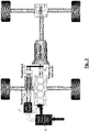
- FIG. 1 schematically shows the drive concept of a vehicle 1 whose primary drive is formed by an internal combustion engine 2, which is arranged in the embodiment shown here in the region of the front wheels 3, 4 defined front axle.
- a crankshaft 5 of the internal combustion engine is coupled to an input 7 of a transmission 8 via a clutch 6, which is also referred to below as "third clutch".
- An output of the transmission is coupled via a propeller shaft to an input 10 of a rear axle 11, which distributes the drive power through output shafts 12, 13 on rear wheels 14, 15.
- the supercharger arrangement has a low-pressure exhaust gas turbocharger 16, which sucks in ambient air 17 and precompressed. Pre-compressed air 18 is further compressed by means of a high-pressure loader 19 and fed to the intake tract of the internal combustion engine 2.
- the low-pressure exhaust gas turbocharger 16 has a turbine wheel, which is not shown here in detail, which is arranged in the exhaust tract of the internal combustion engine 2 and which drives a compressor wheel (likewise not shown).
- the high-pressure charger 19 may likewise be an exhaust gas turbocharger or a conventional flow compressor or supercharger.
- a supercharger shaft 20 of the high-pressure charger 19 can be coupled to an electric machine 22 via a clutch 21, which is also referred to below as "first clutch".
- the electric machine 22 is electrically connected to an electrical energy storage 23, which may be a battery or capacitor arrangement.
- a rotor 24 of the electric machine can thus be rotationally coupled via the first clutch 21 to the high-pressure charger 19.
- the rotor 24 can be coupled via a coupling 25, which is also referred to below as “second clutch”, and via a transmission stage 26 to the "drive train", ie in the exemplary embodiment shown here with the input shaft 7 of the transmission 8 ,
- FIG. 2 shows the operating state "stationary drive” at high load and low speed (within the low-end torque operating range).
- a typical situation is driving on a pass road.
- the three clutches 6, 21 and 25 are closed.
- the electric machine 22 can be "bridged", ie passive.
- the drive train may also be coupled to the loader 19 via the electric machine 22.
- the torque delivered by the internal combustion engine 2 flows through the third clutch 6, the transmission 8 and the rear axle 11 to the rear wheels 14, 15. Part of the power generated by the engine 2 is diverted via the translation stage 26 and via the clutches 25 and 21 to ( mechanical) drive of the high pressure loader 19 is used.
- the internal combustion engine 2 is thus charged in this operating state by the exhaust gas turbocharger 16, ie by flow energy of the exhaust gas of the internal combustion engine as well as by a part of the high-pressure charger 19 driving, generated by the internal combustion engine 2 itself mechanical power.
- FIG. 3 shows the operating state stationary drive at higher load and higher speed (stationary drive outside of the low-end torque operating range).
- the first and the second clutch 21, 25 are each open.
- the third clutch 6 is closed.
- the rotational speed of the internal combustion engine is sufficiently high, so that the engine power required by the driver can already be generated by charging the internal combustion engine by means of the low-pressure exhaust gas turbocharger 16 alone.
- the high-pressure charger 19 may be passive, ie deactivated in this operating state.
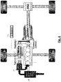
- FIG. 4 shows the operating state accelerated travel at low speed and requested high load, d. h within the low-end torque operating range.
- the first clutch 21 is closed, the second clutch 25 is opened and the third clutch 6 is also closed.
- the internal combustion engine 2 is charged in two stages via the low-pressure turbocharger 16 and via the high-pressure feeder 19.
- the high-pressure charger 19 is electrically driven in this operating state by the electric machine 22, which is supplied from the energy storage 23 with electrical energy.
- FIG. 5 shows the accelerated drive mode at higher speed and higher load (accelerated travel outside the low end torque range).
- the two clutches 21, 25 are opened and the third clutch 6 is closed.
- the high-pressure charger 19 is thus not driven by the electric machine 22.
- the required supercharger power is provided much more exclusively by the low pressure exhaust gas turbocharger 16.
- FIG. 6 shows the operating state "recuperation” in which the clutches 21 and 6 are opened and the clutch 25 is closed.
- the internal combustion engine 2 is thus decoupled from the drive train.
- the pending during the thrust and braking operation on the transmission input shaft 7 power is fed via the translation stage 26 and the clutch 25 in the here working as a generator electric machine 22.
- the generated electrical energy is then buffered in the electrical memory 23.
Landscapes
- Engineering & Computer Science (AREA)
- Mechanical Engineering (AREA)
- Chemical & Material Sciences (AREA)
- Combustion & Propulsion (AREA)
- Transportation (AREA)
- General Engineering & Computer Science (AREA)
- Power Engineering (AREA)
- Automation & Control Theory (AREA)
- Supercharger (AREA)
- Control Of Vehicle Engines Or Engines For Specific Uses (AREA)
- Electric Propulsion And Braking For Vehicles (AREA)
Description
- Die vorliegende Erfindung betrifft ein Fahrzeug gemäß dem Oberbegriff des Patentanspruches 1 sowie ein Verfahren gemäß dem Oberbegriff des Patentanspruches 14.
- Ein derartiges Fahrzeug bzw. ein derartiges Verfahren ist aus der
DE 10 2006 045 937 A1 bekannt. - Fahrzeugantriebe, insbesondere von Personenkraftfahrzeugen, werden heutzutage üblicherweise so ausgelegt, dass sowohl stationäre Leistungsbedarfe (Konstantfahrt) und quasistationäre Leistungsbedarfe (Konstantfahrt mit geringer Beschleunigung) als auch instationäre Leistungsbedarfe (Fahrt mit stärkerer Beschleunigung bis hin zu maximaler Beschleunigung) durch den Antrieb abgedeckt sind. In der Regel haben die instationären Leistungsbedarfe einen erheblich geringeren Zeitanteil als die stationären oder quasistationären Leistungsbedarfe. In den meisten Betriebszuständen des Fahrzeugs liegt somit eine erhebliche Übermotorisierung vor.
- Bei Fahrzeugen mit Verbrennungsmotoren als Antrieb beobachtet man seit geraumer Zeit einen Trend zum "Downsizing" der Verbrennungsmotoren , d. h. einen Trend zu Motoren mit geringerem Hubraum und oftmals auch weniger Zylindern. Um dennoch die gewünschten Fahrleistungen zu erzielen, werden die Verbrennungsmotoren zunehmend höher aufgeladen. Als Lader zur Aufladung des Verbrennungsmotors, d.h. zur Druckerhöhung der Eintrittsluft, werden dabei ganz überwiegend Abgasturbolader (ATL) eingesetzt, welche die im Abgas des Verbrennungsmotors enthaltene Enthalpie über eine Turbine-Verdichter-Einheit zur Verdichtung bzw. zur Erhöhung des Druckniveaus der dem Verbrennungsmotor zugeführten Luft verwenden. Verbrennungsmotoren mit rein strömungsmechanisch angetriebenen Abgasturboladern weisen jedoch beim Beschleunigen aus dem Niedrigzahlbereich heraus bekanntermaßen ein zeitverzögertes Ansprechverhalten auf, das häufig mit dem Begriff "Turboloch" umschrieben wird, und fahrverhaltens seitig negativ empfunden wird.
- Aus der
DE 10 2006 053 037 A1 ist ein Verbrennungsmotor mit Abgasturbolader bekannt, der unterstützend durch eine elektrische Maschine angetrieben werden kann, wodurch sich das Ansprechverhalten des Motors beim Beschleunigen aus dem Niedrigdrehzahlbereich heraus gegenüber herkömmlichen aufgeladenen Motoren verbessert. - Antriebssysteme mit elektrisch angetriebenem Lader sind ferner aus der
DE 10 2007 057 224 A1 sowie aus derDE 10 2006 034 825 A1 bekannt. Zum technischen Hintergrund der Erfindung zählen ferner dieDE 42 03 528 C2 ,DE 28 40 375 ,DE 100 52 555 A1 ,DE 10 2006 059 664 A1 ,DE 42 12 984 A1 ,DE 44 29 855 C1 ,GB 2390871 A WO 2008/075130 A1 ,WO 2009/014488 A2 ,WO 2008/020184 A1 sowie dieUS 4233815 A . - Alternative Ansätze werden auch mit diversen Hybridkonzepten verfolgt, bei denen der Verbrennungsmotor z.B. beim Beschleunigen von einem Elektromotor unterstützt wird (elektrische Boost-Funktion). Eine elektrische Boost-Funktion ist aber nur bei relativ niedrigen Geschwindigkeiten spürbar. Bei höheren Geschwindigkeiten übersteigt der für einen spürbaren zusätzlichen Beschleunigungseffekt erforderliche elektrische Leistungsbedarf die in derzeitigen Fahrzeugen tatsächlich installierte elektrische Leistung in der Regel deutlich. Für eine auch bei höheren Geschwindigkeiten spürbare Boostfunktion ist in der Regel eine elektrische Leistung von mehr als 100 KW erforderlich. Aufgrund der limitierten technischen Möglichkeiten der derzeit verfügbaren elektrischen Speichersysteme ist eine elektrische Antriebsunterstützung daher nur für eine relativ kurze Zeitdauer bzw. nur mit begrenzter Leistung möglich.
- Aufgabe der Erfindung ist es, ein Fahrzeug mit aufgeladenem Verbrennungsmotor zu schaffen, das insbesondere im stationären Betrieb bei niedriger bis mittlerer Last hocheffizient ist und das beim Beschleunigen aus dem stationären Betrieb heraus ein sehr gutes Ansprechverhalten aufweist, sowie ein entsprechendes Verfahren zum Betreiben eines solchen Fahrzeugs anzugeben.
- Diese Aufgabe wird durch die Merkmale der Patentansprüche 1 bzw. 14 gelöst. Vorteilhafte Ausgestaltungen und Weiterbildungen der Erfindung sind den Unteransprüchen zu entnehmen.
- Ausgangspunkt der Erfindung ist ein Fahrzeug, mit einem Verbrennungsmotor, mindestens einem "Lader" und einer elektrischen Maschine, die drehmomentübertragend mit dem Lader koppelbar ist und zum Antrieb bzw. zur Antriebsunterstützung des Laders vorgesehen ist.
- Der in der vorliegenden Beschreibung sowie in den Patentansprüchen verwendete Begriff "Lader" ist äußerst breit auszulegen; er umfasst grundsätzlich jegliche "Vorrichtung", die zu Erhöhung des Drucks der dem Verbrennungsmotor zugeführten Luft eingesetzt werden kann. Der Begriff "Lader" umfasst insbesondere Strömungsverdichter, wie z.B. Radialverdichter, Kompressoren bzw. Verdrängerlader sowie Abgasturbolader. Ein Abgasturbolader weist bekanntermaßen ein in einem Abgasstrom des Verbrennungsmotors angeordnetes Turbinenrad auf, welches ein Verdichterrad antreibt. Im Unterschied zu herkömmlichen, rein strömungstechnisch angetriebenen Abgasturboladern kann das Verdichterrad bzw. die Turboladerwelle unterstützend oder auch rein elektromotorisch von der elektrischen Maschine angetrieben werden.
- "Drehmomentübertragend koppelbar" im Sinne der Erfindung bedeutet, dass während mancher Betriebszustände des Fahrzeugs ein Kraftschluss zwischen der elektrischen Maschine und dem Lader zum Zwecke des Antreibens des Laders erzeugt werden kann.
- Der Kern der Erfindung besteht darin, dass zusätzlich auch der Antriebsstrang des oben beschriebenen Fahrzeugs drehmomentübertragend mit der einen elektrischen Maschine koppelbar ist.
- Der Begriff "Antriebsstrang" umfasst hier grundsätzlich sowohl einzelne als auch alle Vortriebsleistung übertragenden Komponenten, die im Drehmomentpfad zwischen der Kurbelwelle des Verbrennungsmotors und den Antriebsrädern des Fahrzeugs angeordnet sind. Im Sinne der Erfindung kann der Begriff Antriebsstrang auch die Kurbelwelle und andere Verbindungselemente, die eine unmittelbare oder mittelbare Kraftübertragung bzw. Drehmomentübertragung auf den Antriebsstrang ermöglichen, umfassen.
- Gemäß der Erfindung ist die mit der elektrischen Maschine erzeugte Antriebsleistung zumindest nicht primär zur Einspeisung in den Antriebsstrang vorgesehen, sondern primär zum Antrieb des Laders, was im Vergleich zu den diversen bekannten Hybridfahrzeugkonzepten energetisch wesentlich effizienter ist. Die elektrische Energie wird also primär indirekt in den thermodynamischen Verbrennungsprozess eingespeist.
- Die Auslegung des Fahrzeugantriebs ist vergleichbar mit der eines Kraftwerksprozesses. Der den Basisantrieb bildende Verbrennungsmotor deckt die "Grundlast", d.h. die für stationäre oder quasi stationäre Fahrzustände (Konstantfahrt sowie Konstantfahrt mit Beschleunigungen von z.B. weniger als 0,5 m/s2) erforderliche Basisleistung zur Verfügung. Temporär entstehende Spitzenlasten werden über den Systemverbund "Verbrennungsgrundmotor mit elektrisch unterstützter Laderfunktion" abgedeckt.
- Gemäß der Erfindung kann die elektrische Maschine aber nicht nur als Elektromotor zum Antreiben des Laders oder des Antriebsstrangs eingesetzt werden, sondern darüber hinaus auch als Generator zum Rekuperieren und Umwandeln kinetischer Energie aus dem Antriebsstrang in elektrische Energie. Die in Schub- bzw. Bremsphasen mittels der elektrischen Maschine gewonnene elektrische Energie kann in einen elektrischen Energiespeicher, wie z. B. eine Batterie- oder Kondensatoranordnung, eingespeist und zwischengespeichert werden.
- In Betriebszuständen, in denen eine hohe Motorleistung abgerufen wird, kann die generatorisch gewonnene elektrische Energie zum Betreiben der elektrischen Maschine und somit zum Antrieb bzw. zur Antriebsunterstützung des Laders eingesetzt werden. Besonders vorteilhaft ist ein derartiger elektrischer bzw. elektrisch unterstützter Lader, wenn es darum geht, das Fahrzeug zügig aus dem stationären Betrieb heraus zu beschleunigen. Ein elektrischer bzw. elektrisch unterstützter Lader kann aufgrund der spontan verfügbaren elektrischen Energie über die elektrische Maschine aus einem niedrigen Drehzahlbereich nahezu verzögerungsfrei auf Nenndrehzahl beschleunigt werden, während ein herkömmlicher Abgasturbolader aufgrund des zeitlich verzögerten Enthalpieaufbaus im Abgasstrom ein zeitverzögertes Hochlaufverhalten aufweist.
- Neben dem beschriebenen Vorteil, dass bei erfindungsgemäßer Ausführung des Fahrzeugs kinetische Energie des Fahrzeugs während Brems- und Schubphasen in Form von Bremsenergierückgewinnung in elektrische Energie gewandelt und somit zurückgewonnen werden kann, kann diese elektrische Energie insbesondere während Beschleunigungsphasen auch hocheffizient zum Aufbau der Beschleunigung des Fahrzeugs genutzt werden, dadurch dass der elektrisch angetriebene Lader spontan auf seinen Nennbetriebspunkt hochgefahren werden kann. Dies ermöglicht überdies, den Hubraum des Grundmotors des Verbrennungsmotors bei Beibehaltung gleich guter oder teilweise sogar verbesserter Response-Eigenschaften weiter zu reduzieren, woraus ein weiterer Effizienzgewinn des Fahrzeugs resultiert. Ein wesentlicher Vorteil der erfindungsgemäßen Ausführung des Fahrzeugs liegt auch in dem verminderten Systemaufwand durch die Nutzung ein- und derselben elektrischen Maschine zum generatorischen und motorischen Betrieb in Abhängigkeit des Betriebszustands des Fahrzeugs. Dies ist nur deswegen möglich, weil die betroffenen Betriebszustände - einerseits Schub- und/oder Bremsbetrieb, andererseits Beschleunigung oder Konstantfahrt - nie gleichzeitig auftreten.
- Nach einer Weiterbildung der Erfindung ist (funktional betrachtet) zwischen der elektrischen Maschine und dem Lader eine erste mechanische Kopplungseinrichtung vorgesehen, die einen offenen Zustand einnehmen kann, in dem der Läufer der elektrischen Maschine von einer Antriebswelle des Laders entkoppelt ist bzw. einen geschlossenen Zustand, in dem die elektrische Maschine und der Lader drehmomentübertragend gekoppelt sind. Für eine Kopplung bzw. Entkopplung der elektrischen Maschine mit dem Antriebsstrang bzw. von dem Antriebsstrang des Fahrzeugs ist funktional betrachtet "zwischen" der elektrischen Maschine und dem Antriebsstrang eine zweite Kopplungseinrichtung vorgesehen, die ebenfalls einen offenen bzw. einen geschlossenen Zustand einnehmen kann. Im offenen Zustand ist die elektrische Maschine vom Antriebsstrang entkoppelt. Im geschlossenen Zustand hingegen ist die elektrische Maschine mit dem Antriebsstrang des Fahrzeugs gekoppelt. In Schub- bzw. Bremsphasen ermöglicht dies eine Rekuperation kinetischer Energie des Fahrzeugs. Je nach installierter elektrischer Leistung kann die elektrische Maschine bei geschlossener zweiter Kopplungseinrichtung zum Rangieren des Fahrzeugs, als Antriebsunterstützung für den Verbrennungsmotor oder sogar zum rein elektrischen Fahren oder eingesetzt werden.
- Der Antriebsstrang kann hierzu über eine Übersetzungseinrichtung, z. B. einen Kettentrieb, einen Riementrieb, eine Zahnradstufe o.ä., sowie die zweite Kopplungseinrichtung mit der elektrischen Maschine gekoppelt sein.
- Zusätzlich zu den beiden oben erwähnten Kopplungseinrichtungen kann eine dritte mechanische Kopplungseinrichtung vorgesehen sein, über die der Verbrennungsmotor mit dem Antriebsstrang koppelbar bzw. gekoppelt ist. Durch "Öffnen" der dritten Kopplungseinrichtung kann der Verbrennungsmotor z. B. in Schub- bzw. Bremsphasen vom Antriebsstrang abkoppelt werden, was sich günstig auf den Rekuperationswirkungsgrad auswirkt. Auch in Betriebszuständen, in denen rein elektrisch gefahren wird, d. h. in denen der Antriebsstrang ausschließlich von der oben erwähnten oder einer anderen im Fahrzeug verbauten elektrischen Maschine angetrieben wird, ist es von Vorteil, den Verbrennungsmotor durch Öffnen der dritten Kupplung abzukoppeln, da dadurch Motorschleppverluste vermieden werden. Mittels der "wahlfrei" schaltbaren Kupplungseinrichtungen ist eine bedarfsgerechte Zu- bzw. Abschaltung des "Generatormotors" möglich.
- Bei den mechanischen Kopplungseinrichtungen kann es sich beispielsweise um elektrisch, elektromagnetisch, hydraulisch oder anderweitig ansteuerbare bzw. regelbare Kupplungen handeln. Aufgrund schneller Reaktionsfähigkeit und Verschleißfreiheit sind elektromagnetische Kupplungen zu bevorzugen. Grundsätzlich kommen aber auch andere Einrichtungen in Betracht, welche eine Drehmomentkopplung bzw. Drehmomententkopplung ermöglichen. So kann die Funktion der beiden Kupplungen beispielsweise auch vorteilhaft mittels eines Planetenradsatz-Getriebes dargestellt werden.
- Bei der elektrischen Maschine kann es sich z.B. um eine Asynchron-Maschine oder eine Reluktanzmaschine handeln. Insbesondere dazu kann es sich bei der elektrischen Maschine um eine drehzahlgeregelte Maschine handeln, was den Vorteil hat, dass die Leistung der elektrischen Maschine und somit die "Laderleistung" entsprechend der vom Fahrer aktuell angeforderten Antriebsleistung geregelt werden kann. Alternativ oder ergänzend dazu kann zwischen dem Lader und der elektrischen Maschine kann auch eine in Stufen schaltbare Übersetzungseinheit oder eine stufenlose Übersetzungseinrichtung vorgesehen sein.
- Nach einer Weiterbildung der Erfindung ist eine zwei- oder mehrstufige Aufladung vorgesehen. Der mindestens eine Lader wird in diesem Zusammenhang als "zweiter Lader" bezeichnet. Zusätzlich zu dem zweiten Lader ist ein erster Lader vorgesehen, der ebenfalls zur Erhöhung des Drucks der dem Verbrennungsmotor zugeführten Luft vorgesehen ist. Der erste Lader kann "parallel" zum zweiten Lader oder seriell vor dem zweiten Lader angeordnet sein. Im letztgenannten Fall handelt es sich bei dem zweiten Lader um einen "Hochdrucklader", der den Druck der Ansaugluft von einem ersten, durch den ersten Lader erzeugten Druckniveau auf ein zweites, höheres Druckniveau anhebt. Bei dem ersten Lader, der im Falle einer "Registeraufladung" auch als "Niederdrucklader" bezeichnet wird, kann es sich ebenfalls um einen Abgasturbolader handeln.
- Zusammenfassend werden mit der Erfindung folgenden Vorteile erreicht:
- einfache Darstellbarkeit einer effektiven und effizienten elektrischen bzw. elektrisch unterstützten "Boost-Funktion" (Antriebsunterstützung für den Verbrennungsmotor) und Optimierung des Ansprechverhaltens des Verbrennungsmotors;
- verminderter Systemaufwand (Komponentenanzahl, Kosten, Bauraum) zur Darstellung einer Generatorfunktion und der elektrischen "Boost"-Funktion durch Mehrfachverwendung der elektrischen Maschine;
- freie Skalierbarkeit des Systemverbunds;
- energetische Optimierung des Antriebsgesamtsystems mit erheblicher Verbrauchsminderung ohne Einbußen stationärer oder dynamischer Fahrleistung.
- einfache Darstellbarkeit einer E-Fahrfunktion.
- Im Folgenden wird die Erfindung im Zusammenhang mit den Zeichnungen näher erläutert. Es zeigen:
- Figur 1
- das Grundprinzip eines Fahrzeugs gemäß der Erfindung in schematischer Darstellung;
- Figur 2
- den Betriebszustand Stationärfahrt innerhalb des sogenannten Low-End-Torque Betriebsbereichs;
- Figur 3
- den Betriebszustand Stationärfahrt außerhalb des sogenannten Low-End-Torque Betriebsbereichs;
- Figur 4
- den Betriebszustand beschleunigte Fahrt innerhalb des sogenannten Low-End-Torque Betriebsbereichs;
- Fig. 5
- den Betriebszustand beschleunigte Fahrt außerhalb des sogenannten Low-End-Torque Betriebsbereichs;
- Figur 6
- den Betriebszustand Schubbetrieb bzw. verzögerte Fahrt.
- Die in den Figuren verwendete Abkürzung EMG steht für "Elektro-Motor-Generator" und bezeichnet die erfindungsgemäß ausgeführte elektrische Maschine, die in manchen Betriebszuständen des Fahrzeugs generatorisch und in anderen Betriebszuständen des Fahrzeugs motorisch betrieben werden kann.
-
Figur 1 zeigt schematisch das Antriebskonzept eines Fahrzeugs 1 dessen Primärantrieb durch einen Verbrennungsmotor 2 gebildet ist, der bei dem hier gezeigten Ausführungsbeispiel im Bereich der durch Vorderräder 3, 4 definierten Vorderachse angeordnet ist. Eine Kurbelwelle 5 des Verbrennungsmotors ist über eine Kupplung 6, die im Folgenden auch als "dritte Kupplung" bezeichnet wird, mit einem Eingang 7 eines Getriebes 8 gekoppelt. Ein Ausgang des Getriebes ist über eine Gelenkwelle mit einem Eingang 10 eines Hinterachsgetriebes 11 gekoppelt, welche die Antriebsleistung über Abtriebswellen 12, 13 auf Hinterräder 14, 15 verteilt. - Dem Verbrennungsmotor 2 zugeordnet ist eine zweistufige Laderanordnung. Die Laderanordnung weist einen Niederdruckabgasturbolader 16 auf, der Umgebungsluft 17 ansaugt und vorverdichtet. Vorverdichtete Luft 18 wird mittels eines Hochdruckladers 19 weiter verdichtet und dem Ansaugtrakt des Verbrennungsmotors 2 zugeführt. Der Niederdruckabgasturbolader 16 weist ein hier nicht näher dargestelltes Turbinenrad auf, das im Abgastrakt des Verbrennungsmotors 2 angeordnet ist und das ein Verdichterrad (ebenfalls nicht dargestellt) antreibt.
- Bei dem Hochdrucklader 19 kann es sich ebenfalls um einen Abgasturbolader oder um einen herkömmlichen Strömungsverdichter oder Verdrängerlader handeln. Eine Laderwelle 20 des Hochdruckladers 19 ist über eine Kupplung 21, die im Folgenden auch als "erste Kupplung" bezeichnet wird, mit einer elektrischen Maschine 22 koppelbar. Die elektrische Maschine 22 ist elektrisch mit einem elektrischen Energiespeicher 23, bei dem es sich um eine Batterie- oder Kondensatoranordnung handeln kann, verbunden. Ein Läufer 24 der elektrischen Maschine kann über die erste Kupplung 21 somit mit dem Hochdrucklader 19 drehgekoppelt werden. Alternativ oder gleichzeitig kann der Läufer 24 über eine Kupplung 25, die im Folgenden auch als "zweite Kupplung" bezeichnet wird, sowie über eine Übersetzungsstufe 26 mit dem "Antriebsstrang" gekoppelt werden, d. h. bei dem hier gezeigten Ausführungsbeispiel mit der Eingangswelle 7 des Getriebes 8.
-
Figur 2 zeigt den Betriebszustand "Stationärfahrt" bei hoher Last und geringer Drehzahl (innerhalb des Low-End-Torque-Betriebsbereichs). Eine typische Situation ist das Befahren einer Passstraße. In diesem Zustand sind die drei Kupplungen 6, 21 und 25 geschlossen. Die elektrische Maschine 22 kann hierbei "überbrückt", d. h. passiv sein. Alternativ dazu kann der Antriebsstrang aber auch über die elektrische Maschine 22 mit dem Lader 19 gekoppelt sein. Das vom Verbrennungsmotor 2 gelieferte Drehmoment fließt über die dritte Kupplung 6, das Getriebe 8 und das Hinterachsgetriebe 11 zu den Hinterrädern 14, 15. Ein Teil der vom Verbrennungsmotor 2 erzeugten Leistung wird über die Übersetzungsstufe 26 abgezweigt und über die Kupplungen 25 und 21 zum (mechanischen) Antrieb des Hochdruckladers 19 verwendet. Der Verbrennungsmotor 2 wird in diesem Betriebszustand somit durch den Abgasturbolader 16, d. h. durch Strömungsenergie des Abgases des Verbrennungsmotors sowie durch einen Teil der den Hochdrucklader 19 antreibenden, vom Verbrennungsmotor 2 selbst erzeugten mechanischen Leistung aufgeladen. -
Figur 3 zeigt den Betriebszustand Stationärfahrt bei höherer Last und höherer Drehzahl (Stationärfahrt außerhalb des Low-End-Torque-Betriebsbereichs). In diesem Betriebszustand sind die erste und die zweite Kupplung 21, 25 jeweils geöffnet. Die dritte Kupplung 6 ist geschlossen. In diesem Betriebszustand ist die Drehzahl des Verbrennungsmotors hinreichend groß, so dass die vom Fahrer geforderte Motorleistung bereits allein durch Aufladung des Verbrennungsmotors mittels des Niederdruckabgasturboladers 16 erzeugt werden kann. Der Hochdrucklader 19 kann in diesem Betriebszustand passiv, d.h. deaktiviert sein. -
Figur 4 zeigt den Betriebszustand beschleunigte Fahrt bei geringer Drehzahl und angeforderter hoher Last, d. h innerhalb des Low-End-Torque-Betriebsbereichs. In diesem Betriebszustand ist die erste Kupplung 21 geschlossen, die zweite Kupplung 25 geöffnet und die dritte Kupplung 6 ist ebenfalls geschlossen. Der Verbrennungsmotor 2 wird in diesem Betriebszustand zweistufig über den Niederdruckabgasturbolader 16 und über den Hochdruckiader 19 aufgeladen. Der Hochdrucklader 19 wird in diesem Betriebszustand elektrisch von der elektrischen Maschine 22 angetrieben, welche aus dem Energiespeicher 23 mit elektrischer Energie versorgt wird. -
Figur 5 zeigt den Betriebszustand beschleunigte Fahrt bei höherer Drehzahl und höherer Last (beschleunigte Fahrt außerhalb des Low-End-TorqueBetriebsbereichs). In diesem Betriebszustand sind die beiden Kupplungen 21, 25 geöffnet und die dritte Kupplung 6 ist geschlossen. Der Hochdrucklader 19 wird somit nicht von der elektrischen Maschine 22 angetrieben. Die erforderliche Laderleistung wird viel mehr ausschließlich von dem Niederdruckabgasturbolader 16 erbracht. -
Figur 6 zeigt den Betriebszustand "Rekuperation", in dem die Kupplungen 21 und 6 geöffnet sind und die Kupplung 25 geschlossen ist. Der Verbrennungsmotor 2 ist somit vom Antriebsstrang abgekoppelt. Die im Schub- bzw. Bremsbetrieb an der Getriebeeingangswelle 7 anstehende Leistung wird über die Übersetzungsstufe 26 und die Kupplung 25 in die hier als Generator arbeitende elektrische Maschine 22 eingespeist. Die erzeugte elektrische Energie wird dann im elektrischen Speicher 23 zwischengespeichert.
Claims (16)
- Fahrzeug (1), mit- einem Verbrennungsmotor (2), der zum Antreiben eines Antriebsstrangs (7 - 13) des Fahrzeugs vorgesehen ist,- mindestens einem Lader (19), der zur Erhöhung des Drucks der dem Verbrennungsmotor (2) zugeführten Luft vorgesehen ist,- einer elektrischen Maschine, die drehmomentübertragend mit dem Lader (19) koppelbar bzw. gekoppelt und zum Antrieb bzw. zur Antriebsunterstützung des Laders (19) vorgesehen ist, wobei- der Antriebsstrang (7 - 13) drehmomentübertragend mit der elektrischen Maschine (22) koppelbar bzw, gekoppelt ist, wobei zwischen dem Antriebsstrang (7-13) und der elektrischen Maschine (22) eine durch eine Kupplung gebildete zweite Kopplungseinrichtung (25)
vorgesehen ist, die zumindest einen offenen bzw. einen geschlossenen Zustand einnehmen kann, wobei im offenen Zustand der zweiten Kopplungseinrichtung (25) der Antriebsstrang (7-13) über die zweite Kopplungseinrichtung (25) von der elektrischen Maschine (22) abgekoppelt ist und im geschlossenen Zustand der zweiten Kopplungseinrichtung (25) der Antriebsstrang (7 - 13) über die zweite Kopplungseinrichtung (25) mit der elektrischen Maschine (22) gekoppelt ist,
dadurch gekennzeichnet, dass• der mindestens eine Lader (19) ein zweiter Lader ist und zusätzlich dazu ein erster als Abgasturbolader ausgebildeter Lader (16) vorgesehen ist, der ebenfalls zur Erhöhung des Drucks der von dem Verbrennungsmotor (2) angesaugten Luft vorgesehen ist und• in Strömungsrichtung der Ansaugluft nach dem ersten Lader ein Bypass so angeordnet ist, dass der zweite Lader von zumindest einem Teil der Ansaugluft bypassierbar ist. - Fahrzeug nach Anspruch 1, dadurch gekennzeichnet, dass der Antriebsstrang (7 - 13) über die elektrische Maschine (22) drehmomentübertragend mit dem Lader (19) koppelbar ist.
- Fahrzeug nach Anspruch 1, dadurch gekennzeichnet, dass der Antriebsstrang (7 - 13) unter Umgehung der elektrischen Maschine (22) drehmomentübertragend mit dem Lader (19) koppelbar ist.
- Fahrzeug nach einem der Ansprüche 1 bis 3, dadurch gekennzeichnet, dass zwischen dem Lader (19) und der elektrischen Maschine (22) eine erste Kopplungseinrichtung (21) vorgesehen ist, die zumindest einen offenen Zustand bzw. einen geschlossenen Zustand einnehmen kann, wobei im offenen Zustand der ersten Kopplungseinrichtung (21) die elektrische Maschine (22) über die erste Kopplungseinrichtung (21) von dem Lader (19) abgekoppelt ist und im geschlossenen Zustand der ersten Kopplungseinrichtung (21) die elektrische Maschine (22) über die erste Kopplungseinrichtung (21) mit dem Lader (19) gekoppelt ist.
- Fahrzeug nach einem der Ansprüche 1 bis 4, dadurch gekennzeichnet, dass zwischen dem Antriebsstrang (7 - 13) und der elektrischen Maschine eine Übersetzungseinrichtung (26) angeordnet ist.
- Fahrzeug nach Anspruch 5, dadurch gekennzeichnet, dass die Übersetzungseinrichtung (26) einen Kettentrieb und/oder einen Riementrieb und/oder mindestens eine Zahnradstufe umfasst.
- Fahrzeug nach einem der Ansprüche 1 bis 6, dadurch gekennzeichnet, dass der mindestens eine Lader (19) als Verdrängerlader, insbesondere als Kompressor, ausgeführt ist.
- Fahrzeug nach einem der Ansprüche 1 bis 6, dadurch gekennzeichnet, dass der mindestens eine Lader (19) als Abgasturbolader ausgeführt ist.
- Fahrzeug nach einem der Ansprüche 1 bis 6, dadurch gekennzeichnet, dass mindestens eine Lader (19) als Strömungsverdichter ausgeführt ist.
- Fahrzeug nach einem der Ansprüche 1 bis 9, dadurch gekennzeichnet, dass der zweite Lader (19) ein Hochdrucklader ist, der den Druck der Ansaugluft von einem ersten, durch den ersten Lader (16) erzeugten Druckniveau auf ein zweites, höheres Druckniveau erhöht.
- Fahrzeug nach einem der Ansprüche 1 bis 10, dadurch gekennzeichnet, dass der Verbrennungsmotor (2) mittels einer dritten Kopplungseinrichtung (6) mit dem dem Verbrennungsmotor abgewandten Teil des Antriebsstrangs (7 - 13) koppelbar ist.
- Fahrzeug nach einem der Ansprüche 1 bis 11, dadurch gekennzeichnet, dass die erste und/oder die zweite und/oder die dritte Kopplungseinrichtung eine elektromagnetische Kupplung ist.
- Fahrzeug nach einem der Ansprüche 1 bis 12, dadurch gekennzeichnet, dass in elektrischer Verbindung mit der elektrischen Maschine zusätzlich ein elektrischer Energiespeicher zur Speicherung von elektrischer Energie (22) angeordnet ist.
- Verfahren zum Betreiben eines Fahrzeugs (1), das von einer mindestens einem Lader (19) mit Luft beaufschlagten Verbrennungsmotor (2) über einen Antriebsstrang (7-13) angetrieben wird, wobei• der Lader (19) zumindest während eines ersten Betriebszustands des Fahrzeugs (1), insbesondere während einer Beschleunigung des Fahrzeugs, von einer elektrischen Maschine (22) angetrieben wird,• zumindest während eines zweiten Betriebszustands des Fahrzeugs (1), insbesondere während eines Schubbetriebs und/oder Bremsbetriebs des Fahrzeugs, die elektrische Maschine (22) drehmomentübertragend mit dem Antriebsstrang (7 - 13) des Fahrzeugs (1) gekoppelt wird und die elektrische Maschine während zumindest eines zeitlichen Teils des zweiten Betriebszustands generatorisch arbeitet, wobei der Antriebsstrang in dem zweiten Betriebszustand durch Schließen einer zwischen dem Antriebsstrang (7-13) und der elektrischen Maschine (22) angeordneten Kupplung (25) mit der elektrischen Maschine (22) gekoppelt wird,dadurch gekennzeichnet, dass• der mindestens eine Lader (19) ein zweiter Lader ist und zusätzlich dazu ein erster als Abgasturbolader ausgebildeter Lader (16) vorgesehen ist, wobei mittels der beiden Lader (16, 19) seriell oder parallel der Druck der dem Verbrennungsmotor (2) zugeführten Luft erhöht wird und• in Strömungsrichtung der Ansaugluft nach dem ersten Lader ein Bypass so angeordnet ist, dass der zweite Lader von zumindest einem Teil der Ansaugluft bypassierbar ist.
- Verfahren nach Anspruch 14, dadurch gekennzeichnet, dass zumindest während eines dritten Betriebszustands des Fahrzeugs, insbesondere während einer Konstantfahrt des Fahrzeugs bei niedriger Motordrehzahl des Verbrennungsmotors, der Lader (19) drehmomentübertragend mit dem Antriebsstrang (7 - 13) gekoppelt wird und über die elektrische Maschine (22) oder unter Umgehung der elektrischen Maschine (22) mechanisch vom Antriebsstrang (7 -13) angetrieben wird.
- Verfahren nach Anspruch 14 oder 15, dadurch gekennzeichnet,
dass während eines vierten Betriebszustands des Fahrzeugs (1), insbesondere während einer Konstantfahrt und/oder Beschleunigung, die elektrische Maschine (22) drehmomentübertragend mit dem Antriebsstrang (7-13) des Fahrzeugs (1) gekoppelt wird und der Antriebsstrang (7 - 13) zumindest während eines zeitlichen Teils des vierten Betriebszustands ausschließlich von der elektrischen Maschine (22) oder unterstützend durch die elektrische Maschine (22) angetrieben wird.
Applications Claiming Priority (2)
| Application Number | Priority Date | Filing Date | Title |
|---|---|---|---|
| DE102009034510A DE102009034510A1 (de) | 2009-07-24 | 2009-07-24 | Fahrzeug mit aufgeladenem Verbrennungsmotor sowie Verfahren zum Betreiben eines Fahrzeugs mit aufgeladenem Verbrennungsmotor |
| PCT/EP2010/059040 WO2011009693A1 (de) | 2009-07-24 | 2010-06-25 | Fahrzeug mit aufgeladenem verbrennungsmotor sowie verfahren zum betreiben eines fahrzeugs mit aufgeladenem verbrennungsmotor |
Publications (2)
| Publication Number | Publication Date |
|---|---|
| EP2456629A1 EP2456629A1 (de) | 2012-05-30 |
| EP2456629B1 true EP2456629B1 (de) | 2017-03-29 |
Family
ID=43259912
Family Applications (1)
| Application Number | Title | Priority Date | Filing Date |
|---|---|---|---|
| EP10728206.3A Active EP2456629B1 (de) | 2009-07-24 | 2010-06-25 | Fahrzeug mit aufgeladenem verbrennungsmotor sowie verfahren zum betreiben eines fahrzeugs mit aufgeladenem verbrennungsmotor |
Country Status (5)
| Country | Link |
|---|---|
| US (1) | US8959912B2 (de) |
| EP (1) | EP2456629B1 (de) |
| JP (1) | JP2012530876A (de) |
| DE (1) | DE102009034510A1 (de) |
| WO (1) | WO2011009693A1 (de) |
Families Citing this family (38)
| Publication number | Priority date | Publication date | Assignee | Title |
|---|---|---|---|---|
| US11352963B2 (en) * | 2008-07-09 | 2022-06-07 | Herbert U. Fluhler | Internal combustion engine with improved efficiency |
| DE102011012095B4 (de) * | 2011-02-23 | 2015-07-02 | Hrvoje Salinovic | AMICES II : Hybridisierung der Brennkraftmotorsysteme nach dem Additionsprinzip |
| DE102011013520A1 (de) * | 2011-03-10 | 2012-09-13 | Benteler Automobiltechnik Gmbh | Magnetkupplung für Druckwellenladeranordnung sowie Verfahren zum Betreiben einer derartigen Druckwellenladeranordnung |
| CN103562517B (zh) * | 2011-05-30 | 2016-09-14 | Fpt发动机研究公司 | 增压涡轮复合混合发动机装置 |
| WO2013004595A1 (en) * | 2011-07-07 | 2013-01-10 | Kasi Technologies Ab | Hybrid system comprising a supercharging system and method for operation |
| DE102011079036B4 (de) | 2011-07-12 | 2018-12-20 | Mtu Friedrichshafen Gmbh | Brennkraftmaschinen-System, Wasserfahrzeug und Verfahren zum Betrieb eines Schiffsversorgungsnetzes mit einer Brennkraftmaschine |
| US9287455B2 (en) | 2011-09-22 | 2016-03-15 | Sensor Electronic Technology, Inc. | Deep ultraviolet light emitting diode |
| DE102012100865B4 (de) * | 2012-02-02 | 2016-10-27 | Gkn Driveline International Gmbh | Antriebsanordnung mit elektrischer Maschine und Kraftfahrzeug mit einer solchen Antriebsanordnung |
| WO2014042891A1 (en) * | 2012-09-14 | 2014-03-20 | Eaton Corporation | Control system for vehicle drive system having supercharger and accessories |
| DE102012021339A1 (de) * | 2012-10-31 | 2014-04-30 | Eads Deutschland Gmbh | Unbemanntes Luftfahrzeug und Betriebsverfahren hierfür |
| EP2927037A4 (de) * | 2012-11-29 | 2017-03-29 | Nissan Motor Co., Ltd | Kraftwerk für ein fahrzeug |
| WO2014150265A2 (en) * | 2013-03-15 | 2014-09-25 | Eaton Corporation | Dual ratio drive for variable speed hybrid electric supercharger assembly |
| GB2515106B (en) * | 2013-06-14 | 2015-09-23 | Jaguar Land Rover Ltd | Supercharger and Generator or Motor Assembly |
| EP3063384A4 (de) * | 2013-10-28 | 2017-08-09 | Eaton Corporation | Verstärkersystem mit turbo und hybridantriebslader |
| US9789756B2 (en) * | 2014-02-12 | 2017-10-17 | Palo Alto Research Center Incorporated | Hybrid vehicle with power boost |
| US9751521B2 (en) | 2014-04-17 | 2017-09-05 | Palo Alto Research Center Incorporated | Control system for hybrid vehicles with high degree of hybridization |
| US9676382B2 (en) | 2014-04-17 | 2017-06-13 | Palo Alto Research Center Incorporated | Systems and methods for hybrid vehicles with a high degree of hybridization |
| EP3135520A4 (de) * | 2014-04-22 | 2017-05-10 | Panasonic Intellectual Property Management Co., Ltd. | Fahrzeugantriebsvorrichtung |
| JP6481193B2 (ja) * | 2014-06-13 | 2019-03-13 | 三菱自動車工業株式会社 | 電動車両 |
| US9500124B2 (en) * | 2014-11-13 | 2016-11-22 | Caterpillar Inc. | Hybrid powertrain and method for operating same |
| DE102014118816A1 (de) * | 2014-12-17 | 2016-06-23 | Dr. Ing. H.C. F. Porsche Aktiengesellschaft | Luftsystem für einen Kraftfahrzeugmotor sowie Verfahren zur Rückgewinnung von Energie in einem Antriebsstrang |
| US11105259B2 (en) | 2015-02-03 | 2021-08-31 | Williams International Co., L.L.C. | Turbo-electric turbo-compounding method |
| US11105258B2 (en) | 2015-02-03 | 2021-08-31 | Williams International Co., L.L.C. | Turbo-electric turbo-compounding system |
| US9862262B2 (en) * | 2015-07-30 | 2018-01-09 | Ford Global Technologies, Llc | Hybrid vehicle powertrain |
| DE102015015696A1 (de) * | 2015-12-04 | 2017-06-08 | Audi Ag | Antriebseinrichtung für ein Kraftfahrzeug, entsprechendes Kraftfahrzeug sowie Verfahren zum Betreiben einer Antriebseinrichtung |
| GB2540446B (en) | 2016-01-07 | 2018-12-12 | Ford Global Tech Llc | Method and system to deliver smooth engine torque |
| JP6380446B2 (ja) * | 2016-03-30 | 2018-08-29 | トヨタ自動車株式会社 | 車両の制御装置 |
| DE102016219642A1 (de) * | 2016-10-10 | 2018-04-12 | Handtmann Systemtechnik Gmbh & Co. Kg | Antriebsvorrichtung für ein Kraftfahrzeug, Kraftfahrzeug und Verfahren |
| GB2561932A (en) * | 2017-04-28 | 2018-10-31 | John Bayram Peter | Clean diesel & other eco-boost engines with throttled exhaust systems |
| RU195793U1 (ru) * | 2019-11-21 | 2020-02-05 | Хайдер Ибрагим Куса | Мобильное зарядное устройство |
| JP7431065B2 (ja) * | 2020-03-10 | 2024-02-14 | カワサキモータース株式会社 | 電動過給機付き乗物 |
| US12454906B2 (en) | 2021-05-14 | 2025-10-28 | Garrett Transportation I Inc. | Electric boost device control for turbocharger |
| FR3130207B1 (fr) * | 2021-12-10 | 2024-04-19 | Renault Sas | Dispositif de couplage combinant un crabot et un embrayage |
| FR3130208B1 (fr) * | 2021-12-10 | 2023-10-27 | Renault Sas | Dispositif de couplage combinant un crabot et un embrayage |
| IT202200017580A1 (it) * | 2022-08-25 | 2024-02-25 | Ferrari Spa | Automobile provvista di un motore a combustione interna sovralimentato |
| KR102841192B1 (ko) * | 2023-06-09 | 2025-08-01 | 국립공주대학교 산학협력단 | 전기 더블 차저 시스템 |
| EP4656431A1 (de) * | 2024-05-31 | 2025-12-03 | Deere & Company | Gesteuertes motorunterstützungssystem |
| DE102024133278A1 (de) * | 2024-11-14 | 2026-05-21 | Dr. Ing. H.C. F. Porsche Aktiengesellschaft | Antriebssystem eines Hybridfahrzeugs, Verfahren zum Betreiben eines Antriebssystems und Hybridfahrzeug |
Citations (1)
| Publication number | Priority date | Publication date | Assignee | Title |
|---|---|---|---|---|
| JP2005299797A (ja) * | 2004-04-12 | 2005-10-27 | Toyota Motor Corp | ハイブリッド車両の発進時制御方法 |
Family Cites Families (33)
| Publication number | Priority date | Publication date | Assignee | Title |
|---|---|---|---|---|
| US2585029A (en) * | 1947-10-23 | 1952-02-12 | Nettel Frederick | Self-powered turbosupercharger starter system for internalcombustion engines |
| US2503289A (en) * | 1948-04-05 | 1950-04-11 | Supercharged internal-combustion | |
| US2654991A (en) * | 1950-09-09 | 1953-10-13 | Nettel Frederick | Control for engine turbosupercharger systems |
| FR2179310A5 (de) * | 1972-04-06 | 1973-11-16 | France Etat | |
| US4233815A (en) * | 1970-05-05 | 1980-11-18 | Etat Francais | Methods of supercharging a diesel engine, in supercharged diesel engines, and in supercharging units for diesel engines |
| DE2840375A1 (de) | 1978-09-16 | 1980-04-10 | Maschf Augsburg Nuernberg Ag | Abgasturbolader fuer dieselmotoren |
| JPH01313626A (ja) * | 1988-06-10 | 1989-12-19 | Isuzu Motors Ltd | 回転電機付ターボチャージャの駆動装置 |
| JPH0211822A (ja) * | 1988-06-29 | 1990-01-16 | Isuzu Motors Ltd | 回転電機付ターボチャージャの駆動装置 |
| JP2526100B2 (ja) * | 1988-07-18 | 1996-08-21 | 株式会社 いすゞセラミックス研究所 | 過給機の制御装置 |
| DE4203528C2 (de) | 1992-02-07 | 1995-06-08 | Man Nutzfahrzeuge Ag | Kraftfahrzeug mit mittels Abgasturbolader aufladbarer Brennkraftmaschine und hydrostatisch-mechanischem Antrieb der Nebenaggregate |
| DE4212984C2 (de) | 1992-02-07 | 1995-07-06 | Man Nutzfahrzeuge Ag | Kraftfahrzeug mit mittels Abgasturbolader aufladbarer Brennkraftmaschine und hydrostatisch-mechanischem Antrieb der Nebenaggregate |
| DE4429855C1 (de) | 1994-08-23 | 1995-08-17 | Daimler Benz Ag | Aufgeladene Brennkraftmaschine mit mechanischer Hochtriebsmöglichkeit eines Abgasturboladers |
| JP2002512337A (ja) * | 1998-04-16 | 2002-04-23 | 3カー−ヴァルナー・トゥルボズュステームズ・ゲーエムベーハー | ターボチャージ付内燃機関 |
| DE19941705A1 (de) * | 1998-09-09 | 2000-03-16 | Luk Lamellen & Kupplungsbau | Antriebsstrang |
| AU1527300A (en) * | 1998-11-26 | 2000-06-19 | Jacobus Abraham Fouche | Supercharged internal combustion engine with electrically driven compressor |
| DE10052555A1 (de) | 2000-10-24 | 2002-05-08 | Peter Ingelheim | Aktiv regelbares Aufladesystem für Verbrennungsmotoren und seine Regelungen |
| JP3922105B2 (ja) * | 2002-02-06 | 2007-05-30 | 株式会社デンソー | エンジン複合回転電機 |
| GB2390871B (en) * | 2002-07-16 | 2005-11-16 | Drivetec | Automotive superchargers |
| US6871499B1 (en) * | 2003-12-20 | 2005-03-29 | Honeywell Interntional, Inc. | Oil pressure detector for electric assisted turbocharger |
| DE102004029828A1 (de) * | 2004-06-19 | 2006-01-19 | Daimlerchrysler Ag | Abgasturbolader für eine Brennkraftmaschine und Verfahren zum Betrieb eines Agbasturboladers |
| DE102006034825A1 (de) | 2005-08-09 | 2007-02-15 | Robert Bosch Gmbh | Vorrichtung zur Energieumsetzung |
| DE102006059664A1 (de) | 2006-01-12 | 2007-07-19 | Luk Lamellen Und Kupplungsbau Beteiligungs Kg | Kraftfahrzeugantriebsstrang |
| GB0616127D0 (en) * | 2006-08-14 | 2006-09-20 | Nexxtdrive Ltd | A method of operating a supercharger |
| DE102006045937B4 (de) * | 2006-09-28 | 2019-11-07 | Hrvoje Salinovic | Aufladesystem für eine Brennkraftmaschine in Hybridausführung |
| DE102006053037A1 (de) | 2006-11-10 | 2008-05-15 | Bayerische Motoren Werke Ag | Antriebssteuersystem für ein (Neben-)Aggregat eines Kraftfahrzeugs, insbesondere für einen Turbolader einer Brennkraftmaschine |
| JP4906925B2 (ja) * | 2006-12-19 | 2012-03-28 | ルノー・トラックス | 自動車車両用パワーユニットおよび該パワーユニットを備えた車両 |
| WO2008075130A1 (en) * | 2006-12-19 | 2008-06-26 | Renault Trucks | Power unit for an automotive vehicle and vehicle including such a power unit |
| DE102007010027A1 (de) * | 2007-03-01 | 2008-09-11 | Dr. Ing. H.C. F. Porsche Aktiengesellschaft | Antriebsstrang, zugehöriges Betriebsverfahren und Kraftfahrzeug |
| GB0708835D0 (en) * | 2007-05-08 | 2007-06-13 | Nexxtdrive Ltd | Automotive air blowers |
| US7765805B2 (en) * | 2007-07-24 | 2010-08-03 | Kasi Forvaltning I Goteborg Ab | Enhanced supercharging system and an internal combustion engine having such a system |
| US20090048745A1 (en) * | 2007-08-17 | 2009-02-19 | Gm Global Technology Operations, Inc. | Flexible fuel variable boost hybrid powertrain |
| DE102007057224A1 (de) | 2007-11-28 | 2009-01-29 | Daimler Ag | Antriebssystem für ein Kraftfahrzeug |
| US8143732B2 (en) * | 2008-12-15 | 2012-03-27 | Caterpillar Inc. | Stationary genset power system having turbo-compounding |
-
2009
- 2009-07-24 DE DE102009034510A patent/DE102009034510A1/de not_active Ceased
-
2010
- 2010-06-25 EP EP10728206.3A patent/EP2456629B1/de active Active
- 2010-06-25 WO PCT/EP2010/059040 patent/WO2011009693A1/de not_active Ceased
- 2010-06-25 JP JP2012516755A patent/JP2012530876A/ja active Pending
-
2012
- 2012-01-23 US US13/356,095 patent/US8959912B2/en active Active
Patent Citations (1)
| Publication number | Priority date | Publication date | Assignee | Title |
|---|---|---|---|---|
| JP2005299797A (ja) * | 2004-04-12 | 2005-10-27 | Toyota Motor Corp | ハイブリッド車両の発進時制御方法 |
Also Published As
| Publication number | Publication date |
|---|---|
| DE102009034510A1 (de) | 2011-04-14 |
| US8959912B2 (en) | 2015-02-24 |
| EP2456629A1 (de) | 2012-05-30 |
| WO2011009693A1 (de) | 2011-01-27 |
| JP2012530876A (ja) | 2012-12-06 |
| US20120137681A1 (en) | 2012-06-07 |
Similar Documents
| Publication | Publication Date | Title |
|---|---|---|
| WO2011009693A1 (de) | Fahrzeug mit aufgeladenem verbrennungsmotor sowie verfahren zum betreiben eines fahrzeugs mit aufgeladenem verbrennungsmotor | |
| EP2240339B1 (de) | Kraftfahrzeugantriebsstrang | |
| DE102007017777B4 (de) | Turboladeranordnung und turboaufladbare Brennkraftmaschine | |
| EP3207231B1 (de) | Aufladeeinrichtung für einen verbrennungsmotor und betriebsverfahren für die aufladeeinrichtung | |
| DE102010036321A1 (de) | Antriebssystem für ein Kraftfahrzeug und Kraftfahrzeug mit einem derartigen Antriebssystem | |
| DE102006027865A1 (de) | Verbrennungsmotor und Verfahren zur Ladedruckregelung eines Verbrennungsmotors | |
| DE102014017631A1 (de) | Verfahren und Vorrichtung zum Betrieb eines elektromotorisch unterstützten Abgasturboladers eines Kraftfahrzeugs | |
| DE102010011027B4 (de) | Aufladevorrichtung für eine Brennkraftmaschine | |
| DE102014224474A1 (de) | Aufladeeinrichtung für einen Verbrennungsmotor und Betriebsverfahren für die Aufladeeinrichtung | |
| DE102009045624B4 (de) | Generator, welcher mit einem Luftverdichter gekoppelt ist | |
| DE102018110997A1 (de) | Antriebsstrang eines Hybridfahrzeugs und Verfahren zur Steuerung eines Antriebs eines Hybridfahrzeugs | |
| DE102012019967A1 (de) | Aufladeeinrichtung für Brennkraftmaschinen | |
| DE102019203726A1 (de) | Verfahren zum Betreiben eines Antriebsstrangs einer Arbeitsmaschine, Antriebsstrang für eine Arbeitsmaschine und Arbeitsmaschine | |
| DE102018208425B4 (de) | Antriebsstrang für ein Kraftfahrzeug, insbesondere für einen Kraftwagen, sowie Verfahren zum Betreiben eines solchen Antriebsstrangs | |
| DE102011005825A1 (de) | Abgasturbolader mit Überlagerungsgetriebe | |
| DE102015219299A1 (de) | Verbrennungsmotor mit einem durch einen Motorgenerator antreibbaren Zusatzverdichter und Verfahren zum Betreiben eines solchen Verbrennungsmotors | |
| DE102009060181A1 (de) | Abgasturbolader für eine Verbrennungskraftmaschine mit einer Frischgasversorgungsvorrichtung und eine entsprechende Anordnung | |
| DE102008011407A1 (de) | Antriebssystem | |
| DE102009001796A1 (de) | Vorrichtung und Verfahren zur Abgasturboaufladung eines Verbrennungsmotors | |
| DE102017200948A1 (de) | Verfahren zum Betrieb einer turboaufgeladenen Brennkraftmaschine | |
| DE102009038338A1 (de) | Leistungsverteilungssystem | |
| EP3556592B1 (de) | Verfahren zur rückgewinnung von energie des verbrennungsmotors sowie steuergerät zur durchführung des verfahrens | |
| DE102021201894A1 (de) | Verfahren zum Betreiben eines Antriebsstrangs für eine Arbeitsmaschine, Antriebsstrang für eine Arbeitsmaschine und Arbeitsmaschine | |
| DE102014201634A1 (de) | Antriebsstrang und Verfahren zum Betreiben eines solchen | |
| DE102010025196A1 (de) | Verfahren zum Betreiben einer Brennkraftmaschine mit Nutzturbine in einem Wastegate-Kanal |
Legal Events
| Date | Code | Title | Description |
|---|---|---|---|
| PUAI | Public reference made under article 153(3) epc to a published international application that has entered the european phase |
Free format text: ORIGINAL CODE: 0009012 |
|
| 17P | Request for examination filed |
Effective date: 20111122 |
|
| AK | Designated contracting states |
Kind code of ref document: A1 Designated state(s): AL AT BE BG CH CY CZ DE DK EE ES FI FR GB GR HR HU IE IS IT LI LT LU LV MC MK MT NL NO PL PT RO SE SI SK SM TR |
|
| DAX | Request for extension of the european patent (deleted) | ||
| 17Q | First examination report despatched |
Effective date: 20130805 |
|
| GRAP | Despatch of communication of intention to grant a patent |
Free format text: ORIGINAL CODE: EPIDOSNIGR1 |
|
| INTG | Intention to grant announced |
Effective date: 20161201 |
|
| GRAS | Grant fee paid |
Free format text: ORIGINAL CODE: EPIDOSNIGR3 |
|
| GRAA | (expected) grant |
Free format text: ORIGINAL CODE: 0009210 |
|
| AK | Designated contracting states |
Kind code of ref document: B1 Designated state(s): AL AT BE BG CH CY CZ DE DK EE ES FI FR GB GR HR HU IE IS IT LI LT LU LV MC MK MT NL NO PL PT RO SE SI SK SM TR |
|
| REG | Reference to a national code |
Ref country code: GB Ref legal event code: FG4D Free format text: NOT ENGLISH |
|
| REG | Reference to a national code |
Ref country code: CH Ref legal event code: EP |
|
| REG | Reference to a national code |
Ref country code: AT Ref legal event code: REF Ref document number: 879397 Country of ref document: AT Kind code of ref document: T Effective date: 20170415 |
|
| REG | Reference to a national code |
Ref country code: IE Ref legal event code: FG4D Free format text: LANGUAGE OF EP DOCUMENT: GERMAN |
|
| REG | Reference to a national code |
Ref country code: DE Ref legal event code: R096 Ref document number: 502010013383 Country of ref document: DE |
|
| REG | Reference to a national code |
Ref country code: FR Ref legal event code: PLFP Year of fee payment: 8 |
|
| PG25 | Lapsed in a contracting state [announced via postgrant information from national office to epo] |
Ref country code: HR Free format text: LAPSE BECAUSE OF FAILURE TO SUBMIT A TRANSLATION OF THE DESCRIPTION OR TO PAY THE FEE WITHIN THE PRESCRIBED TIME-LIMIT Effective date: 20170329 Ref country code: FI Free format text: LAPSE BECAUSE OF FAILURE TO SUBMIT A TRANSLATION OF THE DESCRIPTION OR TO PAY THE FEE WITHIN THE PRESCRIBED TIME-LIMIT Effective date: 20170329 Ref country code: NO Free format text: LAPSE BECAUSE OF FAILURE TO SUBMIT A TRANSLATION OF THE DESCRIPTION OR TO PAY THE FEE WITHIN THE PRESCRIBED TIME-LIMIT Effective date: 20170629 Ref country code: GR Free format text: LAPSE BECAUSE OF FAILURE TO SUBMIT A TRANSLATION OF THE DESCRIPTION OR TO PAY THE FEE WITHIN THE PRESCRIBED TIME-LIMIT Effective date: 20170630 Ref country code: LT Free format text: LAPSE BECAUSE OF FAILURE TO SUBMIT A TRANSLATION OF THE DESCRIPTION OR TO PAY THE FEE WITHIN THE PRESCRIBED TIME-LIMIT Effective date: 20170329 |
|
| REG | Reference to a national code |
Ref country code: NL Ref legal event code: MP Effective date: 20170329 |
|
| PG25 | Lapsed in a contracting state [announced via postgrant information from national office to epo] |
Ref country code: BG Free format text: LAPSE BECAUSE OF FAILURE TO SUBMIT A TRANSLATION OF THE DESCRIPTION OR TO PAY THE FEE WITHIN THE PRESCRIBED TIME-LIMIT Effective date: 20170629 Ref country code: LV Free format text: LAPSE BECAUSE OF FAILURE TO SUBMIT A TRANSLATION OF THE DESCRIPTION OR TO PAY THE FEE WITHIN THE PRESCRIBED TIME-LIMIT Effective date: 20170329 Ref country code: SE Free format text: LAPSE BECAUSE OF FAILURE TO SUBMIT A TRANSLATION OF THE DESCRIPTION OR TO PAY THE FEE WITHIN THE PRESCRIBED TIME-LIMIT Effective date: 20170329 |
|
| PG25 | Lapsed in a contracting state [announced via postgrant information from national office to epo] |
Ref country code: NL Free format text: LAPSE BECAUSE OF FAILURE TO SUBMIT A TRANSLATION OF THE DESCRIPTION OR TO PAY THE FEE WITHIN THE PRESCRIBED TIME-LIMIT Effective date: 20170329 |
|
| PG25 | Lapsed in a contracting state [announced via postgrant information from national office to epo] |
Ref country code: ES Free format text: LAPSE BECAUSE OF FAILURE TO SUBMIT A TRANSLATION OF THE DESCRIPTION OR TO PAY THE FEE WITHIN THE PRESCRIBED TIME-LIMIT Effective date: 20170329 Ref country code: CZ Free format text: LAPSE BECAUSE OF FAILURE TO SUBMIT A TRANSLATION OF THE DESCRIPTION OR TO PAY THE FEE WITHIN THE PRESCRIBED TIME-LIMIT Effective date: 20170329 Ref country code: SK Free format text: LAPSE BECAUSE OF FAILURE TO SUBMIT A TRANSLATION OF THE DESCRIPTION OR TO PAY THE FEE WITHIN THE PRESCRIBED TIME-LIMIT Effective date: 20170329 Ref country code: RO Free format text: LAPSE BECAUSE OF FAILURE TO SUBMIT A TRANSLATION OF THE DESCRIPTION OR TO PAY THE FEE WITHIN THE PRESCRIBED TIME-LIMIT Effective date: 20170329 Ref country code: EE Free format text: LAPSE BECAUSE OF FAILURE TO SUBMIT A TRANSLATION OF THE DESCRIPTION OR TO PAY THE FEE WITHIN THE PRESCRIBED TIME-LIMIT Effective date: 20170329 |
|
| PG25 | Lapsed in a contracting state [announced via postgrant information from national office to epo] |
Ref country code: SM Free format text: LAPSE BECAUSE OF FAILURE TO SUBMIT A TRANSLATION OF THE DESCRIPTION OR TO PAY THE FEE WITHIN THE PRESCRIBED TIME-LIMIT Effective date: 20170329 Ref country code: PL Free format text: LAPSE BECAUSE OF FAILURE TO SUBMIT A TRANSLATION OF THE DESCRIPTION OR TO PAY THE FEE WITHIN THE PRESCRIBED TIME-LIMIT Effective date: 20170329 Ref country code: PT Free format text: LAPSE BECAUSE OF FAILURE TO SUBMIT A TRANSLATION OF THE DESCRIPTION OR TO PAY THE FEE WITHIN THE PRESCRIBED TIME-LIMIT Effective date: 20170731 Ref country code: IS Free format text: LAPSE BECAUSE OF FAILURE TO SUBMIT A TRANSLATION OF THE DESCRIPTION OR TO PAY THE FEE WITHIN THE PRESCRIBED TIME-LIMIT Effective date: 20170729 |
|
| REG | Reference to a national code |
Ref country code: DE Ref legal event code: R097 Ref document number: 502010013383 Country of ref document: DE |
|
| PG25 | Lapsed in a contracting state [announced via postgrant information from national office to epo] |
Ref country code: MC Free format text: LAPSE BECAUSE OF FAILURE TO SUBMIT A TRANSLATION OF THE DESCRIPTION OR TO PAY THE FEE WITHIN THE PRESCRIBED TIME-LIMIT Effective date: 20170329 Ref country code: DK Free format text: LAPSE BECAUSE OF FAILURE TO SUBMIT A TRANSLATION OF THE DESCRIPTION OR TO PAY THE FEE WITHIN THE PRESCRIBED TIME-LIMIT Effective date: 20170329 |
|
| REG | Reference to a national code |
Ref country code: CH Ref legal event code: PL |
|
| PLBE | No opposition filed within time limit |
Free format text: ORIGINAL CODE: 0009261 |
|
| STAA | Information on the status of an ep patent application or granted ep patent |
Free format text: STATUS: NO OPPOSITION FILED WITHIN TIME LIMIT |
|
| 26N | No opposition filed |
Effective date: 20180103 |
|
| REG | Reference to a national code |
Ref country code: IE Ref legal event code: MM4A |
|
| PG25 | Lapsed in a contracting state [announced via postgrant information from national office to epo] |
Ref country code: CH Free format text: LAPSE BECAUSE OF NON-PAYMENT OF DUE FEES Effective date: 20170630 Ref country code: LU Free format text: LAPSE BECAUSE OF NON-PAYMENT OF DUE FEES Effective date: 20170625 Ref country code: IE Free format text: LAPSE BECAUSE OF NON-PAYMENT OF DUE FEES Effective date: 20170625 Ref country code: LI Free format text: LAPSE BECAUSE OF NON-PAYMENT OF DUE FEES Effective date: 20170630 |
|
| PG25 | Lapsed in a contracting state [announced via postgrant information from national office to epo] |
Ref country code: SI Free format text: LAPSE BECAUSE OF FAILURE TO SUBMIT A TRANSLATION OF THE DESCRIPTION OR TO PAY THE FEE WITHIN THE PRESCRIBED TIME-LIMIT Effective date: 20170329 |
|
| REG | Reference to a national code |
Ref country code: BE Ref legal event code: MM Effective date: 20170630 |
|
| REG | Reference to a national code |
Ref country code: FR Ref legal event code: PLFP Year of fee payment: 9 |
|
| REG | Reference to a national code |
Ref country code: AT Ref legal event code: MM01 Ref document number: 879397 Country of ref document: AT Kind code of ref document: T Effective date: 20170625 |
|
| PG25 | Lapsed in a contracting state [announced via postgrant information from national office to epo] |
Ref country code: BE Free format text: LAPSE BECAUSE OF NON-PAYMENT OF DUE FEES Effective date: 20170630 |
|
| PG25 | Lapsed in a contracting state [announced via postgrant information from national office to epo] |
Ref country code: MT Free format text: LAPSE BECAUSE OF FAILURE TO SUBMIT A TRANSLATION OF THE DESCRIPTION OR TO PAY THE FEE WITHIN THE PRESCRIBED TIME-LIMIT Effective date: 20170329 |
|
| PG25 | Lapsed in a contracting state [announced via postgrant information from national office to epo] |
Ref country code: AT Free format text: LAPSE BECAUSE OF NON-PAYMENT OF DUE FEES Effective date: 20170625 |
|
| RIC2 | Information provided on ipc code assigned after grant |
Ipc: F02B 33/34 20060101ALI20110209BHEP Ipc: F02B 37/04 20060101ALI20110209BHEP Ipc: F02B 37/013 20060101ALI20110209BHEP Ipc: B60K 6/48 20071001AFI20110209BHEP Ipc: F02B 39/10 20060101ALI20110209BHEP Ipc: B60W 20/00 20160101ALI20110209BHEP Ipc: F02B 37/10 20060101ALI20110209BHEP Ipc: F02B 39/12 20060101ALI20110209BHEP |
|
| PG25 | Lapsed in a contracting state [announced via postgrant information from national office to epo] |
Ref country code: HU Free format text: LAPSE BECAUSE OF FAILURE TO SUBMIT A TRANSLATION OF THE DESCRIPTION OR TO PAY THE FEE WITHIN THE PRESCRIBED TIME-LIMIT; INVALID AB INITIO Effective date: 20100625 |
|
| PG25 | Lapsed in a contracting state [announced via postgrant information from national office to epo] |
Ref country code: CY Free format text: LAPSE BECAUSE OF NON-PAYMENT OF DUE FEES Effective date: 20170329 |
|
| PG25 | Lapsed in a contracting state [announced via postgrant information from national office to epo] |
Ref country code: MK Free format text: LAPSE BECAUSE OF FAILURE TO SUBMIT A TRANSLATION OF THE DESCRIPTION OR TO PAY THE FEE WITHIN THE PRESCRIBED TIME-LIMIT Effective date: 20170329 |
|
| PG25 | Lapsed in a contracting state [announced via postgrant information from national office to epo] |
Ref country code: TR Free format text: LAPSE BECAUSE OF FAILURE TO SUBMIT A TRANSLATION OF THE DESCRIPTION OR TO PAY THE FEE WITHIN THE PRESCRIBED TIME-LIMIT Effective date: 20170329 |
|
| PG25 | Lapsed in a contracting state [announced via postgrant information from national office to epo] |
Ref country code: AL Free format text: LAPSE BECAUSE OF FAILURE TO SUBMIT A TRANSLATION OF THE DESCRIPTION OR TO PAY THE FEE WITHIN THE PRESCRIBED TIME-LIMIT Effective date: 20170329 |
|
| P01 | Opt-out of the competence of the unified patent court (upc) registered |
Effective date: 20230503 |
|
| PGFP | Annual fee paid to national office [announced via postgrant information from national office to epo] |
Ref country code: DE Payment date: 20250605 Year of fee payment: 16 |
|
| PGFP | Annual fee paid to national office [announced via postgrant information from national office to epo] |
Ref country code: GB Payment date: 20250620 Year of fee payment: 16 |
|
| PGFP | Annual fee paid to national office [announced via postgrant information from national office to epo] |
Ref country code: FR Payment date: 20250627 Year of fee payment: 16 |
|
| PGFP | Annual fee paid to national office [announced via postgrant information from national office to epo] |
Ref country code: IT Payment date: 20250630 Year of fee payment: 16 |