EP2455154A1 - Kohlendioxidwiedergewinnungsvorrichtung und Kohlendioxidwiedergewinnungsverfahren - Google Patents
Kohlendioxidwiedergewinnungsvorrichtung und Kohlendioxidwiedergewinnungsverfahren Download PDFInfo
- Publication number
- EP2455154A1 EP2455154A1 EP11188938A EP11188938A EP2455154A1 EP 2455154 A1 EP2455154 A1 EP 2455154A1 EP 11188938 A EP11188938 A EP 11188938A EP 11188938 A EP11188938 A EP 11188938A EP 2455154 A1 EP2455154 A1 EP 2455154A1
- Authority
- EP
- European Patent Office
- Prior art keywords
- carbon dioxide
- liquid
- carbon
- release device
- lean
- Prior art date
- Legal status (The legal status is an assumption and is not a legal conclusion. Google has not performed a legal analysis and makes no representation as to the accuracy of the status listed.)
- Granted
Links
Images


Classifications
-
- B—PERFORMING OPERATIONS; TRANSPORTING
- B01—PHYSICAL OR CHEMICAL PROCESSES OR APPARATUS IN GENERAL
- B01D—SEPARATION
- B01D53/00—Separation of gases or vapours; Recovering vapours of volatile solvents from gases; Chemical or biological purification of waste gases, e.g. engine exhaust gases, smoke, fumes, flue gases, aerosols
- B01D53/14—Separation of gases or vapours; Recovering vapours of volatile solvents from gases; Chemical or biological purification of waste gases, e.g. engine exhaust gases, smoke, fumes, flue gases, aerosols by absorption
- B01D53/1456—Removing acid components
- B01D53/1475—Removing carbon dioxide
-
- B—PERFORMING OPERATIONS; TRANSPORTING
- B01—PHYSICAL OR CHEMICAL PROCESSES OR APPARATUS IN GENERAL
- B01D—SEPARATION
- B01D53/00—Separation of gases or vapours; Recovering vapours of volatile solvents from gases; Chemical or biological purification of waste gases, e.g. engine exhaust gases, smoke, fumes, flue gases, aerosols
- B01D53/14—Separation of gases or vapours; Recovering vapours of volatile solvents from gases; Chemical or biological purification of waste gases, e.g. engine exhaust gases, smoke, fumes, flue gases, aerosols by absorption
- B01D53/1418—Recovery of products
-
- B—PERFORMING OPERATIONS; TRANSPORTING
- B01—PHYSICAL OR CHEMICAL PROCESSES OR APPARATUS IN GENERAL
- B01D—SEPARATION
- B01D53/00—Separation of gases or vapours; Recovering vapours of volatile solvents from gases; Chemical or biological purification of waste gases, e.g. engine exhaust gases, smoke, fumes, flue gases, aerosols
- B01D53/14—Separation of gases or vapours; Recovering vapours of volatile solvents from gases; Chemical or biological purification of waste gases, e.g. engine exhaust gases, smoke, fumes, flue gases, aerosols by absorption
- B01D53/1425—Regeneration of liquid absorbents
-
- B—PERFORMING OPERATIONS; TRANSPORTING
- B01—PHYSICAL OR CHEMICAL PROCESSES OR APPARATUS IN GENERAL
- B01D—SEPARATION
- B01D2252/00—Absorbents, i.e. solvents and liquid materials for gas absorption
- B01D2252/10—Inorganic absorbents
- B01D2252/103—Water
-
- B—PERFORMING OPERATIONS; TRANSPORTING
- B01—PHYSICAL OR CHEMICAL PROCESSES OR APPARATUS IN GENERAL
- B01D—SEPARATION
- B01D2259/00—Type of treatment
- B01D2259/65—Employing advanced heat integration, e.g. Pinch technology
-
- Y—GENERAL TAGGING OF NEW TECHNOLOGICAL DEVELOPMENTS; GENERAL TAGGING OF CROSS-SECTIONAL TECHNOLOGIES SPANNING OVER SEVERAL SECTIONS OF THE IPC; TECHNICAL SUBJECTS COVERED BY FORMER USPC CROSS-REFERENCE ART COLLECTIONS [XRACs] AND DIGESTS
- Y02—TECHNOLOGIES OR APPLICATIONS FOR MITIGATION OR ADAPTATION AGAINST CLIMATE CHANGE
- Y02C—CAPTURE, STORAGE, SEQUESTRATION OR DISPOSAL OF GREENHOUSE GASES [GHG]
- Y02C20/00—Capture or disposal of greenhouse gases
- Y02C20/40—Capture or disposal of greenhouse gases of CO2
Definitions
- the present invention relates to a carbon dioxide recovery apparatus and a carbon dioxide recovery method.
- the carbon dioxide recovery apparatus includes an absorbing tower which generates a rich liquid by absorbing carbon-dioxide-containing gas into an absorbing liquid, a releasing tower which generates a lean liquid by heating the rich liquid discharged from the absorbing tower to release and separate carbon dioxide along with steam and which returns the lean liquid to the absorbing tower, a first heat exchanger through which the lean liquid to be supplied from the releasing tower to the absorbing tower passes, a second heat exchanger through which carbon-dioxide-containing steam separated at the releasing tower passes, and a splitting device which splits the rich liquid discharged from the absorbing tower to the first and second heat exchangers.
- the rich liquids introduced to the first and second heat exchangers are supplied to the releasing tower after performing heat exchange respectively with the lean liquid and the carbon-dioxide-containing steam.
- the present invention provides a carbon dioxide recovery apparatus and a carbon dioxide recovery method capable of performing effective heat recovery from a lean liquid and carbon-dioxide-containing steam with a rich liquid.
- a carbon dioxide recovery apparatus comprising: an absorbing tower to generate and discharge a rich liquid absorbing carbon dioxide as carbon-dioxide-containing gas is introduced and contacted to an absorbing liquid to absorb carbon dioxide; a carbon dioxide release device to discharge a semi-lean liquid which has steam containing a part of carbon dioxide released by heating the rich liquid discharged from the absorbing tower; and a regeneration tower to generate a lean liquid which has steam containing remaining carbon dioxide released and separated by heating the semi-lean liquid discharged from the carbon dioxide release device and to return the lean liquid to the absorbing tower.
- a carbon dioxide recovery method comprising: generating and discharging a rich liquid which absorbs carbon dioxide as introducing carbon-dioxide-containing gas and contacting the gas to an absorbing liquid to absorb carbon dioxide; discharging a semi-lean liquid which has steam containing a part of carbon dioxide released by heating the rich liquid; and generating a lean liquid which has steam containing remaining carbon dioxide released and separated by heating the semi-lean liquid.
- the carbon dioxide recovery apparatus and the carbon dioxide recovery method of the present invention it is possible to perform effective heat recovery from the lean liquid and the carbon-dioxide-containing steam with the rich liquid.
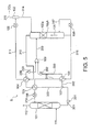
- FIG. 1 illustrates the structure thereof.
- the carbon dioxide recovery apparatus 1 is provided with an absorbing tower 101, carbon dioxide release devices 103, 104, a gas-liquid separator 132, coolers 105, 106, a regeneration tower 102A and a re-boiler 108 as main structural elements.
- the carbon dioxide recovery apparatus 1 is provided with pumps 201, 202, 203, a splitting device 107 and a merging device 109.
- a rich liquid 301 having carbon dioxide absorbed is generated while carbon-dioxide-containing gas 111 is introduced and contacted to an absorbing liquid which absorbs carbon dioxide.
- the absorbing tower 101 for example, being constituted with a counter flow type gas-liquid contacting device is structured to perform gas-liquid contacting between the carbon-dioxide-containing gas 111 supplied from a lower part and a lean liquid 319 flowing down from an upper part.
- the carbon-dioxide-containing gas 111 to be supplied to the absorbing tower 101 may be, for example, combustion exhaust gas, process exhaust gas and the like and may be introduced after receiving a cooling process if required.
- the absorbing liquid may adopt aqueous solution of amine series such as monoethanol-amine (MEA) and diethanol-amine (DEA), for example.
- amine series such as monoethanol-amine (MEA) and diethanol-amine (DEA), for example.
- MEA monoethanol-amine
- DEA diethanol-amine
- Carbon-dioxide-removed gas 112 having carbon dioxide removed is discharged from an upper part of the absorbing tower 101.
- the rich liquid 301 discharged from the absorbing tower 101 is supplied to the splitting device 107 via the pump 201 and is split into rich liquids 302, 303 at a desired flow ratio.
- the rich liquids 302, 303 are heated respectively at the carbon dioxide release devices 103, 104 having a part of carbon dioxide released along with steam and are discharged as being gas-liquid two-phase semi-lean liquids 320, 306 having a part of carbon dioxide removed.
- a lean liquid 316 to be supplied from the regeneration tower 102A to the absorbing tower 101 passes through the carbon dioxide release device 103 being a first carbon dioxide release device.
- carbon-dioxide-containing steam 310 separated at the regeneration tower 102A passes through the carbon dioxide release device 104 being a second carbon dioxide release device.
- the rich liquids 302, 303 supplied respectively to the carbon dioxide release devices 103, 104 are heated owing to heat exchange with the lean liquid 316 and the carbon-dioxide-containing steam 310, so that a part of carbon dioxide is released along with steam.
- Carbon-dioxide-containing steam 311 having a part of water vapor condensed at the carbon dioxide release device 104 is discharged and supplied to the cooler 105 and is discharged to the gas-liquid separator 132 after being cooled owing to refrigerant such as cold water to be supplied from the outside, and then, is discharged from the gas-liquid separator 132 as being separated into carbon dioxide 315 and condensed water 314.
- the semi-lean liquids 320, 306 having a part of carbon dioxide released are merged at the merging device 109 respectively via the pumps 202, 203, and then, are supplied to the regeneration tower 102A.
- the regeneration tower 102A including a loading layer 102a heats the semi-lean liquid 309. Accordingly, the most part of carbon dioxide is separated as being released along with steam and is discharged from an upper part thereof as the carbon-dioxide-containing steam 310.
- the lean liquid 316 having the most part of carbon dioxide removed is returned to the absorbing tower 101.
- the regeneration tower 102A is a counter flow type gas-liquid contacting device, for example.
- heating of a stored liquid is performed at the re-boiler 108 by performing heat-exchange with high temperature steam which is external supply heat.
- the cooler 106 is provided between the carbon dioxide release device 103 and the absorbing tower 101 on a route through which the lean liquid 316 is supplied from the regeneration tower 102A to the absorbing tower 101.
- a lean liquid 318 is cooled owing to refrigerant such as cold water to be supplied from the outside, and then, is returned to the absorbing tower 101 as a lean liquid 319.
- an absorbing process of carbon dioxide in which the rich liquid 301 is generated as the carbon-dioxide-containing gas 111 is absorbed to the absorbing liquid, is performed at the absorbing tower 101.
- the rich liquid 301 discharged from the absorbing tower 101 is split and is supplied to the regeneration tower 102A as the gas-liquid two-phase semi-lean liquids 320, 306 having a part of carbon dioxide released respectively at the carbon dioxide release devices 103, 104. Subsequently, circulation supplying is performed as the carbon-dioxide-containing steam 131 as being heated by the re-boiler 108, and then, remaining carbon-dioxide-containing steam is released.
- the carbon-dioxide-containing steam is discharged from the upper part of the regeneration tower 102A as the carbon-dioxide-containing steam 310 while the lean liquid 316 is returned to the absorbing tower 101.
- the lean liquid 316 discharged from the regeneration tower 102A is supplied to the absorbing tower 101 as passing through the carbon dioxide release device 103 and the cooler 106. Meanwhile, the carbon-dioxide-containing steam 310 separated at the regeneration tower 102A is supplied to the gas-liquid separator 132 as passing through the carbon dioxide release device 104 and the cooler 105.
- the rich liquid 301 discharged from the absorbing tower 101 is introduced to the carbon dioxide release devices 103, 104 as being split at the splitting device 107, and then, is supplied to the regeneration tower 102A after performing heat exchange respectively with the lean liquid 316 and the carbon-dioxide-containing steam 310.
- Temperature of the semi-lean liquids 320, 306 to be introduced to the regeneration tower 102A can be sufficiently raised by utilizing the two carbon dioxide release devices 103, 104, while a part of carbon dioxide is released.
- the releasing of carbon dioxide and water evaporation corresponding thereto are endothermal reactions. Therefore, temperature difference between the rich liquid and the lean liquid in the carbon dioxide release device 103 or temperature difference between the rich liquid and the carbon-dioxide-containing steam in the carbon dioxide release device 104 can be enlarged compared to a case that the rich liquid does not change in phase. Accordingly, heat recovery utilizing the rich liquid from the lean liquid and the carbon-dioxide-containing steam can be performed more effectively.
- the semi-lean liquids 320, 306 can be easily varied into two phases as being liquid and carbon-dioxide-containing steam. Since the degree of being two phases and efficiency of heat recovery can be increased, heat energy for releasing carbon dioxide at the regeneration tower 102A can be further reduced.
- temperature of the lean liquid 318 and the carbon-dioxide-containing steam 311 to be introduced respectively to the coolers 106, 105 can be set low. Accordingly, cooling loss can be suppressed by reducing cooling load at the coolers 106, 105.
- the condensed water 314 separated at the gas-liquid separator 132 is to be returned to the regeneration tower 102A.
- the condensed water 314 may be returned to the absorbing tower 101 or may be merged with the lean liquid 318 after the carbon dioxide release device 103.
- the first embodiment includes the pumps 201 to 203. However, it is not necessarily required to provide all of the pumps. The number thereof can be reduced.
- the splitting device 107 is provided at the outside of the absorbing tower 101 and the flow passage of the rich liquid 301 is connected to the carbon dioxide release devices 103, 104 via two pipes after being split by the splitting device 107.
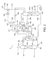
- a carbon dioxide recovery apparatus 2 according to the second embodiment of the present invention will be described with reference to FIG. 2 which illustrates the structure thereof.
- the carbon dioxide recovery apparatus 2 differs in including gas-liquid separators 133, 134, 135 and a merging device 110, and a pump 204.
- the rich liquid 301 discharged from the absorbing tower 101 is supplied to the carbon dioxide release devices 103, 104 as the rich liquids 302, 303 via the splitting device 107.
- the rich liquids 302, 303 are heated respectively having a part of carbon dioxide released along with steam and are discharged as being the gas-liquid two-phase semi-lean liquids 320, 306 having a part of carbon dioxide removed from the liquid.
- the lean liquid 316 to be supplied from the regeneration tower 102A to the absorbing tower 101 passes through the carbon dioxide release device 103.
- the carbon-dioxide-containing steam 310 separated at the regeneration tower 102A passes through the carbon dioxide release device 104 after being merged with carbon-dioxide-containing steam 305, 308 at a merging device 110 as described later.
- the rich liquids 302, 303 supplied respectively to the carbon dioxide release devices 103, 104 are heated owing to heat exchange with the lean liquid 316 and the carbon-dioxide-containing steam 305, 308, 310, so that a part of carbon dioxide is released along with steam.
- the carbon-dioxide-containing steam 311 having a part of water vapor condensed at the carbon dioxide release device 104 is discharged and supplied to the gas-liquid separator 135, and then, is discharged as being separated into carbon-dioxide-containing steam 313 and condensed water 312.
- the carbon-dioxide-containing steam 313 is supplied to the cooler 105 and is discharged to the gas-liquid separator 132 as being cooled owing to refrigerant such as cold water to be supplied from the outside, and then, is discharged from the gas-liquid separator 132 after being separated into the carbon dioxide 315 and the condensed water 314.
- the condensed water 312 discharged from the gas-liquid separator 135 is returned to the regeneration tower 102A via the pump 204 along with the condensed water 314 discharged from the gas-liquid separator 132.
- the semi-lean liquids 320, 306 discharged from the carbon dioxide release devices 103, 104 are separated into carbon-dioxide-containing steam 305, 308 and semi-lean liquids 304, 307 respectively by the gas-liquid separators 133, 134.
- the carbon-dioxide-containing steam 305, 308 are supplied to the merging device 110 to be merged with the carbon-dioxide-containing steam 310 which is discharged from the regeneration tower 102A, and then, is supplied to the carbon dioxide release device 104.
- the semi-lean liquids 304, 307 having a part of carbon dioxide released are merged at the merging device 109 respectively via the pumps 202, 203, and then, are supplied to the regeneration tower 102A.
- the semi-lean liquids 320, 306 can be easily varied into two phases as being liquid and carbon-dioxide-containing steam by setting the pressure in the carbon dioxide release devices 103, 104 to be low. Accordingly, it becomes possible to perform heat recovery more effectively.
- the regeneration tower 102A and the gas-liquid separators 133, 134 are communicated respectively through a gas single phase. Therefore, in a case that distances between the gas-liquid separator 133 and the carbon dioxide release device 103 and between the gas-liquid separator 134 and the carbon dioxide release device 104 are short, pressure loss in pipes is smaller than that of the first embodiment in which the regeneration tower 102A and the carbon dioxide release devices 103, 104 are communicated respectively through a supply line of the gas-liquid two-phase semi-lean liquid. Accordingly, rich liquid pressure in the carbon dioxide release devices 103, 104 can be set low.
- the rich liquid pressure in the carbon dioxide release devices 103, 104 can be set low by the amount of elimination or reduction of liquid phase heads in pipes toward the regeneration tower 102A which are to be noticeable when the carbon dioxide release devices 103, 104 are placed at low positions, the degree of being two phases of the semi-lean liquids 320, 306 can be increased and heat recovery from the lean liquid and the carbon-dioxide-containing steam utilizing the rich liquids can be performed more effectively.
- the semi-lean liquids 304, 307 are supplied to the regeneration tower 102A after having carbon dioxide separated to some extent owing to the gas-liquid separators 133, 134, it is possible to suppress reabsorption of carbon dioxide at the regeneration tower 102A.
- the second embodiment it is also possible to adopt a structure in which the semi-lean liquids 320, 306 are introduced to the gas-liquid separator 133 after being merged and the carbon-dioxide-containing steam 305 separated thereat and the carbon-dioxide-containing steam 310 discharged from the regeneration tower 102A are supplied to the carbon dioxide release device 104 after being merged, as illustrated in FIG. 3 , for example.
- the second embodiment includes the pumps 201 to 204.
- the pumps 201 to 204 are not necessarily required to provide the all, it is also possible to reduce the number thereof by placing the regeneration tower 102A at a low position, and the like.
- a carbon dioxide recovery apparatus 4 according to the third embodiment of the present invention will be described with reference to FIG. 4 which illustrates the structure thereof.
- the carbon dioxide recovery apparatus 4 differs in including carbon dioxide release devices 121, 122, a cooler 113, a gas-liquid separator 136 and pumps 205, 206.
- the rich liquid 301 discharged from the absorbing tower 101 is supplied to the carbon dioxide release device 103 being the first carbon dioxide release device via the splitting device 107 as the rich liquid 302 and is heated having a part of carbon dioxide released along with steam, and then, is discharged as being the gas-liquid two-phase semi-lean liquid 320 having a part of carbon dioxide removed from the liquid.
- the rich liquid 303 is supplied sequentially to the carbon dioxide release devices 121, 122, 104 being the second carbon dioxide release device and is heated thereat respectively having a part of carbon dioxide released along with steam, and then, is discharged as being the gas-liquid two-phase semi-lean liquid 306 having a part of carbon dioxide removed from the liquid.
- the lean liquid 316 to be supplied from the regeneration tower 102A to the absorbing tower 101 passes through the carbon dioxide release device 103 and heats the rich liquid 302 owing to heat exchange with the rich liquid 302. Accordingly, a part of carbon dioxide is released along with steam.
- the carbon-dioxide-containing steam 308 discharged from the gas-liquid separator 134 passes through the carbon dioxide release device 121.
- the carbon-dioxide-containing steam 310 separated at the regeneration tower 102A passes through the carbon dioxide release device 122.
- the carbon-dioxide-containing steam 305 discharged from the gas-liquid separator 133 passes through the carbon dioxide release device 104. Accordingly, the rich liquid 303 sequentially supplied to the carbon dioxide release devices 121, 122, 104 is heated owing to heat exchange respectively with the carbon-dioxide-containing steam 308, 310, 305, so that a part of carbon dioxide is released along with steam.
- the carbon-dioxide-containing steam 128, 311 having a part of water vapor condensed at the carbon dioxide release devices 121, 104 is discharged and supplied to the gas-liquid separator 135 as the carbon-dioxide-containing steam 124 after being supplied to and merged at the merging device 110, and then, is discharged as being separated into the carbon-dioxide-containing steam 313 and the condensed water 312.
- the carbon-dioxide-containing steam 313 is supplied to the cooler 105 and is discharged to the gas-liquid separator 132 as being cooled owing to refrigerant such as cold water to be supplied from the outside, and then, is discharged from the gas-liquid separator 132 after being separated into the carbon dioxide 315 and the condensed water 314.
- the condensed water 312 discharged from the gas-liquid separator 135 is returned to the regeneration tower 102A via the pump 204 along with the condensed water 314 discharged from the gas-liquid separator 132.
- Carbon-dioxide-containing steam 127 having a part of water vapor condensed at the carbon dioxide release device 122 is discharged and supplied to the cooler 113 and is discharged to the gas-liquid separator 136 after being cooled owing to refrigerant such as cold water to be supplied from the outside, and then, discharged from the gas-liquid separator 136 as being separated into carbon dioxide 325 and condensed water 324.
- the condensed water 324 discharged from the gas-liquid separator 136 is returned to the regeneration tower 102A via the pump 206.
- the semi-lean liquids 320, 306 discharged from the carbon dioxide release devices 103, 104 are separated into carbon-dioxide-containing steam 305, 308 and semi-lean liquids 304, 307 respectively by the gas-liquid separators 133, 134.
- the semi-lean liquids 304, 307 having a part of carbon dioxide released are merged at the merging device 109 respectively via the pumps 202, 203, and then, are supplied to the regeneration tower 102A.
- supply lines of the carbon-dioxide-containing steam 305, 308 and a supply line of the carbon-dioxide-containing steam 310 are not merged. Accordingly, being different from the second embodiment, pressure in the gas-liquid separators 133, 134 can be remarkably lowered than pressure in the regeneration tower 102A owing to adjustment of a pressure adjusting valve (not illustrated) provided to a supply line etc. of the carbon dioxide 315.
- each rich liquid pressure in the carbon dioxide release devices 103, 121, 122, 104 can be lowered, the degree of being two phases of the semi-lean liquids 320, 306 can be increased and heat recovery from the lean liquid and the carbon-dioxide-containing steam utilizing the rich liquids can be performed more effectively.
- a carbon dioxide recovery apparatus 5 according to the fourth embodiment of the present invention will be described with reference to FIG. 5 which illustrates the structure thereof.
- the carbon dioxide recovery apparatus 5 according to the fourth embodiment differs in including a lean liquid cooler 123.
- the rich liquid 303 supplied after being split cools the lean liquid 318 discharged from the carbon dioxide release device 103 as being heated thereat. It is possible to reduce usage quantity of high temperature steam supplied at the re-boiler 108 by performing heat recovery from the lean liquid to a maximum extent. Further, it is also possible to suppress power usage quantity by reducing cooling load at the cooler 106.
- a carbon dioxide recovery apparatus 6 according to the fifth embodiment of the present invention will be described with reference to FIG. 6 which illustrates the structure thereof.
- the carbon dioxide release device 104 is arranged at the outside of the regeneration tower 102A.
- the carbon dioxide release device 104 is not arranged at the outside of a regeneration tower 102B. Accordingly, the rich liquid 303 discharged from the splitting device 107 is supplied directly to the regeneration tower 102B. Since the carbon dioxide release device 104 is not arranged at the outside of the regeneration tower 102B, the merging device 109 becomes unnecessary.
- the regeneration tower 102A is provided simply with the loading layer 102a.
- the regeneration tower 102B of the fifth embodiment is provided with a loading layer 102b at the upper stage as well as with the loading layer 102a at the lower stage.
- the rich liquid 303 is supplied from above the loading layer 102b at the upper stage and is moved downward as passing through the loading layer 102b.
- the semi-lean liquid 320 is supplied between the loading layers 102a, 102b and is moved downward as passing through the loading layer 102a at the lower stage.
- the carbon-dioxide-containing steam 131 passes upwards through the loading layers 102a, 102b, so that heat exchange is performed. That is, instead of the carbon dioxide release device 104, the loading layer 102b having a similar function is arranged in the regeneration tower 102B as the second carbon dioxide release device.
- the carbon-dioxide-containing steam contained in the semi-lean liquid 320 also functions as a heating medium for the rich liquid 303 along with the carbon-dioxide-containing steam 131 owing to upward movement thereof after being introduced to the regeneration tower 102B.
- the carbon-dioxide-containing steam 310 discharged from the upper part of the regeneration tower 102B passes through the carbon dioxide release device 104 and the like.
- the carbon-dioxide-containing steam 310 is supplied directly to the cooler 105 and cooled, and is supplied to the gas-liquid separator 132.
- the fifth embodiment since the carbon dioxide release device 104 and the merging device 109 are not provided, it is possible to reduce manufacturing cost requiring less pipes compared to the first embodiment.
- the fifth embodiment includes the pumps 201 to 203. However, it is not necessarily required to provide all of the pumps. The number thereof can be reduced.
- a carbon dioxide recovery apparatus 7 according to the sixth embodiment of the present invention will be described with reference to FIG. 7 which illustrates the structure thereof.
- the carbon dioxide recovery apparatus 7 according to the sixth embodiment differs in including the gas-liquid separator 133.
- the semi-lean liquid 320 discharged from the carbon dioxide release device 103 is separated into the carbon-dioxide-containing steam 305 and the semi-lean liquid 304 by the gas-liquid separator 133.
- the semi-lean liquid 304 is supplied between the loading layers 102a, 102b by the pump 202 and is moved downward as passing through the loading layer 102a at the lower stage.
- the carbon-dioxide-containing steam 305 is supplied at a position of the same height as the semi-lean liquid 304 or higher to the regeneration tower 102B and functions as a heating medium for the semi-lean liquid 303 along with the carbon-dioxide-containing steam 131 as being moved upward.
- the regeneration tower 102B and the gas-liquid separator 133 is communicated through a gas single phase. Therefore, in a case that distance between the gas-liquid separator 133 and the carbon dioxide release device 103 is short, pressure loss in pipes is smaller than that of the fifth embodiment in which the regeneration tower 102B and the carbon dioxide release device 103 are communicated through a supply line of the gas-liquid two-phase semi-lean liquid. Accordingly, rich liquid pressure in the carbon dioxide release device 103 can be set low.
- the rich liquid pressure in the carbon dioxide release device 103 can be set low by the amount of elimination or reduction of a liquid phase head in pipes toward the regeneration tower 102B which is to be noticeable when the carbon dioxide release device 103 is placed at a low position, the degree of being two phases of the semi-lean liquid 320 can be increased and heat recovery from the lean liquid and the carbon-dioxide-containing steam utilizing the rich liquid can be performed more effectively.
- a carbon dioxide recovery apparatus 8 according to the seventh embodiment of the present invention will be described with reference to FIG. 8 which illustrates the structure thereof.
- the carbon dioxide recovery apparatus 8 according to the seventh embodiment differs in including the lean liquid cooler 123.
- the rich liquid 303 supplied after being split cools the lean liquid 318 discharged from the carbon dioxide release device 103 as being heated thereat. It is possible to reduce usage quantity of high temperature steam supplied at the re-boiler 108 by performing heat recovery from the lean liquid to a maximum extent. Further, it is also possible to suppress power usage quantity by reducing cooling load at the cooler 106.
Applications Claiming Priority (1)
| Application Number | Priority Date | Filing Date | Title |
|---|---|---|---|
| JP2010256969A JP5697411B2 (ja) | 2010-11-17 | 2010-11-17 | 二酸化炭素回収装置および二酸化炭素回収方法 |
Publications (2)
| Publication Number | Publication Date |
|---|---|
| EP2455154A1 true EP2455154A1 (de) | 2012-05-23 |
| EP2455154B1 EP2455154B1 (de) | 2017-10-18 |
Family
ID=45062926
Family Applications (1)
| Application Number | Title | Priority Date | Filing Date |
|---|---|---|---|
| EP11188938.2A Active EP2455154B1 (de) | 2010-11-17 | 2011-11-14 | Kohlendioxidwiedergewinnungsvorrichtung und Kohlendioxidwiedergewinnungsverfahren |
Country Status (6)
| Country | Link |
|---|---|
| US (2) | US9155991B2 (de) |
| EP (1) | EP2455154B1 (de) |
| JP (1) | JP5697411B2 (de) |
| CN (2) | CN104759188B (de) |
| AU (1) | AU2011250763B2 (de) |
| CA (1) | CA2757781C (de) |
Cited By (5)
| Publication number | Priority date | Publication date | Assignee | Title |
|---|---|---|---|---|
| CN103521051A (zh) * | 2012-06-25 | 2014-01-22 | 株式会社东芝 | 二氧化碳回收设备及其操作方法 |
| US20140338394A1 (en) * | 2013-05-20 | 2014-11-20 | Kabushiki Kaisha Toshiba | Carbon dioxide separating and capturing apparatus and method of operating same |
| EP2832420A3 (de) * | 2013-07-29 | 2015-06-10 | Kabushiki Kaisha Toshiba | Verfahren und System zur Trennung und zum Sammeln von Kohlendioxid und Betriebsverfahren dafür |
| EP3006099A4 (de) * | 2013-06-04 | 2017-01-18 | Kepco Engineering & Construction Company, Inc. | Kohlendioxidtrennungsvorrichtung mit verbesserter effizienz bei der rückgewinnung fühlbarer wärme unter verwendung von druckreduzierung und phasentrennung |
| WO2024008248A1 (de) * | 2022-07-06 | 2024-01-11 | DGE Dr. Ing. Günther Engineering GmbH | Verfahren zum trennen von methan und kohlendioxid aus biogas und aufbereitungsanlage |
Families Citing this family (24)
| Publication number | Priority date | Publication date | Assignee | Title |
|---|---|---|---|---|
| US8696804B2 (en) | 2010-12-29 | 2014-04-15 | Delphi Technologies, Inc. | Carbon dioxide absorbent fluid for a carbon dioxide sequestering system on a vehicle |
| US9267415B2 (en) | 2010-12-29 | 2016-02-23 | Delphi Technologies, Inc. | Heat exchanger equipped with thermal electric device for engine exhaust carbon dioxide collection system |
| DE102012208223B4 (de) * | 2012-02-22 | 2013-11-07 | Siemens Aktiengesellschaft | Anlage und Verfahren zur Kohlenstoffdioxid- und Wasserabscheidung |
| JP5659176B2 (ja) | 2012-03-06 | 2015-01-28 | 株式会社東芝 | 二酸化炭素回収装置及び二酸化炭素回収方法 |
| CN102895860B (zh) * | 2012-09-29 | 2015-01-07 | 华北电力大学 | 化学吸收co2捕获流程的降耗方法及系统 |
| CA2891715C (en) * | 2012-11-14 | 2022-09-20 | Board Of Regents, The University Of Texas System | Apparatus for and method of removing acidic gas from a gaseous stream and regenerating an absorbent solution |
| JP6170366B2 (ja) * | 2013-07-26 | 2017-07-26 | 株式会社Ihi | 二酸化炭素の回収方法及び回収装置 |
| KR101583462B1 (ko) * | 2013-12-04 | 2016-01-13 | 한국에너지기술연구원 | 에너지 절감형 산성 가스 포집 시스템 및 방법 |
| KR101536153B1 (ko) | 2014-03-06 | 2015-11-20 | 한국에너지기술연구원 | 흡수제 재순환을 이용한 저에너지형 산성가스 포집 시스템 및 방법 |
| US10493397B2 (en) | 2015-07-14 | 2019-12-03 | John E. Stauffer | Carbon dioxide recovery |
| US10040737B2 (en) | 2015-07-14 | 2018-08-07 | John E. Stauffer | Methanol production from methane and carbon dioxide |
| US10293304B2 (en) | 2015-07-14 | 2019-05-21 | John E. Stauffer | Carbon dioxide recovery using an absorption column in combination with osmotic filters |
| US10688435B2 (en) * | 2017-02-27 | 2020-06-23 | Honeywell International Inc. | Dual stripper with water sweep gas |
| KR102319957B1 (ko) * | 2017-12-27 | 2021-11-01 | 한국전력공사 | 이산화탄소 회수 및 발전 시스템 |
| JP7152975B2 (ja) * | 2019-03-20 | 2022-10-13 | 三菱重工エンジニアリング株式会社 | 吸収液再生装置及びco2回収装置並びに吸収液再生方法 |
| CN111715032A (zh) * | 2019-03-22 | 2020-09-29 | 国家能源投资集团有限责任公司 | 一种co2捕集装置及方法 |
| CN110152457A (zh) * | 2019-05-16 | 2019-08-23 | 中石化石油工程技术服务有限公司 | 基于废热回收利用的化学吸收法二氧化碳捕集系统 |
| US20230149852A1 (en) * | 2020-05-01 | 2023-05-18 | Toho Gas Co., Ltd. | Carbon dioxide recovery device |
| CN114632402B (zh) * | 2020-12-16 | 2022-11-11 | 中冶京诚工程技术有限公司 | 烟气二氧化碳捕集系统的捕集方法 |
| CN113041799A (zh) * | 2021-03-12 | 2021-06-29 | 中国华能集团清洁能源技术研究院有限公司 | 一种基于igcc的燃烧前co2捕集系统压力能回收装置 |
| CN113230832B (zh) * | 2021-05-27 | 2022-06-28 | 浙江浙能技术研究院有限公司 | 一种低挥发性有机污染物排放的co2捕集系统及方法 |
| CN114405218A (zh) * | 2022-02-14 | 2022-04-29 | 中国矿业大学 | 一种低分压废气co2捕集与提纯精制工艺 |
| DE102022116799A1 (de) | 2022-07-06 | 2024-01-11 | DGE Dr. Ing. Günther Engineering GmbH | Verfahren zum Trennen von Methan und Kohlendioxid aus Biogas und Aufbereitungsanlage |
| JP2024035966A (ja) * | 2022-09-05 | 2024-03-15 | 株式会社神戸製鋼所 | ガス処理方法及びガス処理装置 |
Citations (3)
| Publication number | Priority date | Publication date | Assignee | Title |
|---|---|---|---|---|
| US20060032377A1 (en) * | 2002-07-03 | 2006-02-16 | Satish Reddy | Split flow process and apparatus |
| WO2009112518A1 (en) * | 2008-03-13 | 2009-09-17 | Shell Internationale Research Maatschappij B.V. | Process for removal of carbon dioxide from a gas |
| JP2009214089A (ja) | 2008-03-13 | 2009-09-24 | Research Institute Of Innovative Technology For The Earth | 二酸化炭素回収装置及び方法 |
Family Cites Families (10)
| Publication number | Priority date | Publication date | Assignee | Title |
|---|---|---|---|---|
| US4184855A (en) * | 1977-12-29 | 1980-01-22 | Union Carbide Corporation | Process for CO2 removal |
| JP2882950B2 (ja) * | 1992-09-16 | 1999-04-19 | 関西電力株式会社 | 燃焼排ガス中の二酸化炭素を除去する方法 |
| JP3381390B2 (ja) * | 1994-06-27 | 2003-02-24 | 石川島播磨重工業株式会社 | 二酸化炭素回収装置 |
| JP3392609B2 (ja) * | 1995-12-01 | 2003-03-31 | 三菱重工業株式会社 | ガス中の炭酸ガスを除去する方法 |
| DE102004011429A1 (de) | 2004-03-09 | 2005-09-29 | Basf Ag | Verfahren zum Entfernen von Kohlendioxid aus Gasströmen mit niedrigen Kohlendioxid-Partialdrücken |
| JP4690659B2 (ja) * | 2004-03-15 | 2011-06-01 | 三菱重工業株式会社 | Co2回収装置 |
| PL2164608T3 (pl) * | 2007-05-29 | 2018-04-30 | University Of Regina | Sposób odzyskiwania składnika gazowego ze strumienia gazu |
| US8435325B2 (en) * | 2008-10-23 | 2013-05-07 | Hitachi, Ltd. | Method and device for removing CO2 and H2S |
| JP2010240629A (ja) * | 2009-04-10 | 2010-10-28 | Toshiba Corp | 二酸化炭素回収システム |
| JP5383338B2 (ja) * | 2009-06-17 | 2014-01-08 | 三菱重工業株式会社 | Co2回収装置及びco2回収方法 |
-
2010
- 2010-11-17 JP JP2010256969A patent/JP5697411B2/ja active Active
-
2011
- 2011-11-11 AU AU2011250763A patent/AU2011250763B2/en active Active
- 2011-11-14 CA CA2757781A patent/CA2757781C/en active Active
- 2011-11-14 EP EP11188938.2A patent/EP2455154B1/de active Active
- 2011-11-16 US US13/298,063 patent/US9155991B2/en active Active
- 2011-11-17 CN CN201510107755.6A patent/CN104759188B/zh active Active
- 2011-11-17 CN CN201110365128.4A patent/CN102527191B/zh active Active
-
2015
- 2015-05-18 US US14/715,291 patent/US9731244B2/en active Active
Patent Citations (3)
| Publication number | Priority date | Publication date | Assignee | Title |
|---|---|---|---|---|
| US20060032377A1 (en) * | 2002-07-03 | 2006-02-16 | Satish Reddy | Split flow process and apparatus |
| WO2009112518A1 (en) * | 2008-03-13 | 2009-09-17 | Shell Internationale Research Maatschappij B.V. | Process for removal of carbon dioxide from a gas |
| JP2009214089A (ja) | 2008-03-13 | 2009-09-24 | Research Institute Of Innovative Technology For The Earth | 二酸化炭素回収装置及び方法 |
Cited By (12)
| Publication number | Priority date | Publication date | Assignee | Title |
|---|---|---|---|---|
| CN103521051A (zh) * | 2012-06-25 | 2014-01-22 | 株式会社东芝 | 二氧化碳回收设备及其操作方法 |
| EP2679295A3 (de) * | 2012-06-25 | 2014-10-01 | Kabushiki Kaisha Toshiba | Kohlenstoffdioxidrückgewinnungsvorrichtung und Verfahren zum Betrieb davon |
| CN103521051B (zh) * | 2012-06-25 | 2016-03-30 | 株式会社东芝 | 二氧化碳回收设备及其操作方法 |
| US10173166B2 (en) | 2012-06-25 | 2019-01-08 | Kabushiki Kaisha Toshiba | Carbon dioxide recovering apparatus and method for operating the same |
| US20140338394A1 (en) * | 2013-05-20 | 2014-11-20 | Kabushiki Kaisha Toshiba | Carbon dioxide separating and capturing apparatus and method of operating same |
| EP2805757A1 (de) * | 2013-05-20 | 2014-11-26 | Kabushiki Kaisha Toshiba | Vorrichtung zur Trennung und zum Sammeln von Kohlendioxid und Betriebsverfahren dafür |
| AU2014200565B2 (en) * | 2013-05-20 | 2015-10-01 | Kabushiki Kaisha Toshiba | Carbon dioxide separating and capturing apparatus and method of operating same |
| US9248397B2 (en) | 2013-05-20 | 2016-02-02 | Kabushiki Kaisha Toshiba | Carbon dioxide separating and capturing apparatus and method of operating same |
| EP3006099A4 (de) * | 2013-06-04 | 2017-01-18 | Kepco Engineering & Construction Company, Inc. | Kohlendioxidtrennungsvorrichtung mit verbesserter effizienz bei der rückgewinnung fühlbarer wärme unter verwendung von druckreduzierung und phasentrennung |
| EP2832420A3 (de) * | 2013-07-29 | 2015-06-10 | Kabushiki Kaisha Toshiba | Verfahren und System zur Trennung und zum Sammeln von Kohlendioxid und Betriebsverfahren dafür |
| US9464842B2 (en) | 2013-07-29 | 2016-10-11 | Kabushiki Kaisha Toshiba | Carbon dioxide separating and capturing system and method of operating same |
| WO2024008248A1 (de) * | 2022-07-06 | 2024-01-11 | DGE Dr. Ing. Günther Engineering GmbH | Verfahren zum trennen von methan und kohlendioxid aus biogas und aufbereitungsanlage |
Also Published As
| Publication number | Publication date |
|---|---|
| JP5697411B2 (ja) | 2015-04-08 |
| CN102527191A (zh) | 2012-07-04 |
| CA2757781C (en) | 2013-10-22 |
| CN104759188B (zh) | 2017-06-30 |
| US20120118162A1 (en) | 2012-05-17 |
| CA2757781A1 (en) | 2012-05-17 |
| AU2011250763A1 (en) | 2012-05-31 |
| US20150258490A1 (en) | 2015-09-17 |
| CN102527191B (zh) | 2015-04-22 |
| AU2011250763B2 (en) | 2015-05-14 |
| CN104759188A (zh) | 2015-07-08 |
| US9731244B2 (en) | 2017-08-15 |
| US9155991B2 (en) | 2015-10-13 |
| JP2012106180A (ja) | 2012-06-07 |
| EP2455154B1 (de) | 2017-10-18 |
Similar Documents
| Publication | Publication Date | Title |
|---|---|---|
| US9731244B2 (en) | Carbon dioxide recovery apparatus and carbon dioxide recovery method | |
| US10005032B2 (en) | Carbon dioxide recovery apparatus and carbon dioxide recovery method | |
| EP2679295B1 (de) | Kohlenstoffdioxidrückgewinnungsvorrichtung und Verfahren zum Betrieb davon | |
| JP6064770B2 (ja) | 二酸化炭素の回収方法及び回収装置 | |
| JP5741690B2 (ja) | 二酸化炭素の回収方法及び回収装置 | |
| JP2012000539A (ja) | 二酸化炭素の回収方法及び回収装置 | |
| JP2009144676A (ja) | エネルギー回収システム | |
| JP6274866B2 (ja) | 二酸化炭素ガス回収装置 | |
| JP2014113546A (ja) | 二酸化炭素回収装置及び二酸化炭素回収方法 | |
| JP6307279B2 (ja) | 二酸化炭素ガス回収装置及び回収方法 | |
| JP5720463B2 (ja) | 二酸化炭素の回収方法及び回収装置 |
Legal Events
| Date | Code | Title | Description |
|---|---|---|---|
| PUAI | Public reference made under article 153(3) epc to a published international application that has entered the european phase |
Free format text: ORIGINAL CODE: 0009012 |
|
| 17P | Request for examination filed |
Effective date: 20111114 |
|
| AK | Designated contracting states |
Kind code of ref document: A1 Designated state(s): AL AT BE BG CH CY CZ DE DK EE ES FI FR GB GR HR HU IE IS IT LI LT LU LV MC MK MT NL NO PL PT RO RS SE SI SK SM TR |
|
| AX | Request for extension of the european patent |
Extension state: BA ME |
|
| 17Q | First examination report despatched |
Effective date: 20151012 |
|
| STAA | Information on the status of an ep patent application or granted ep patent |
Free format text: STATUS: EXAMINATION IS IN PROGRESS |
|
| GRAP | Despatch of communication of intention to grant a patent |
Free format text: ORIGINAL CODE: EPIDOSNIGR1 |
|
| STAA | Information on the status of an ep patent application or granted ep patent |
Free format text: STATUS: GRANT OF PATENT IS INTENDED |
|
| INTG | Intention to grant announced |
Effective date: 20170502 |
|
| GRAS | Grant fee paid |
Free format text: ORIGINAL CODE: EPIDOSNIGR3 |
|
| GRAA | (expected) grant |
Free format text: ORIGINAL CODE: 0009210 |
|
| STAA | Information on the status of an ep patent application or granted ep patent |
Free format text: STATUS: THE PATENT HAS BEEN GRANTED |
|
| AK | Designated contracting states |
Kind code of ref document: B1 Designated state(s): AL AT BE BG CH CY CZ DE DK EE ES FI FR GB GR HR HU IE IS IT LI LT LU LV MC MK MT NL NO PL PT RO RS SE SI SK SM TR |
|
| REG | Reference to a national code |
Ref country code: GB Ref legal event code: FG4D |
|
| REG | Reference to a national code |
Ref country code: CH Ref legal event code: EP |
|
| REG | Reference to a national code |
Ref country code: AT Ref legal event code: REF Ref document number: 937453 Country of ref document: AT Kind code of ref document: T Effective date: 20171115 Ref country code: IE Ref legal event code: FG4D |
|
| REG | Reference to a national code |
Ref country code: DE Ref legal event code: R096 Ref document number: 602011042465 Country of ref document: DE |
|
| REG | Reference to a national code |
Ref country code: NL Ref legal event code: MP Effective date: 20171018 |
|
| REG | Reference to a national code |
Ref country code: LT Ref legal event code: MG4D |
|
| REG | Reference to a national code |
Ref country code: AT Ref legal event code: MK05 Ref document number: 937453 Country of ref document: AT Kind code of ref document: T Effective date: 20171018 |
|
| PG25 | Lapsed in a contracting state [announced via postgrant information from national office to epo] |
Ref country code: NL Free format text: LAPSE BECAUSE OF FAILURE TO SUBMIT A TRANSLATION OF THE DESCRIPTION OR TO PAY THE FEE WITHIN THE PRESCRIBED TIME-LIMIT Effective date: 20171018 |
|
| PG25 | Lapsed in a contracting state [announced via postgrant information from national office to epo] |
Ref country code: SE Free format text: LAPSE BECAUSE OF FAILURE TO SUBMIT A TRANSLATION OF THE DESCRIPTION OR TO PAY THE FEE WITHIN THE PRESCRIBED TIME-LIMIT Effective date: 20171018 Ref country code: FI Free format text: LAPSE BECAUSE OF FAILURE TO SUBMIT A TRANSLATION OF THE DESCRIPTION OR TO PAY THE FEE WITHIN THE PRESCRIBED TIME-LIMIT Effective date: 20171018 Ref country code: ES Free format text: LAPSE BECAUSE OF FAILURE TO SUBMIT A TRANSLATION OF THE DESCRIPTION OR TO PAY THE FEE WITHIN THE PRESCRIBED TIME-LIMIT Effective date: 20171018 Ref country code: LT Free format text: LAPSE BECAUSE OF FAILURE TO SUBMIT A TRANSLATION OF THE DESCRIPTION OR TO PAY THE FEE WITHIN THE PRESCRIBED TIME-LIMIT Effective date: 20171018 Ref country code: NO Free format text: LAPSE BECAUSE OF FAILURE TO SUBMIT A TRANSLATION OF THE DESCRIPTION OR TO PAY THE FEE WITHIN THE PRESCRIBED TIME-LIMIT Effective date: 20180118 |
|
| PG25 | Lapsed in a contracting state [announced via postgrant information from national office to epo] |
Ref country code: LV Free format text: LAPSE BECAUSE OF FAILURE TO SUBMIT A TRANSLATION OF THE DESCRIPTION OR TO PAY THE FEE WITHIN THE PRESCRIBED TIME-LIMIT Effective date: 20171018 Ref country code: AT Free format text: LAPSE BECAUSE OF FAILURE TO SUBMIT A TRANSLATION OF THE DESCRIPTION OR TO PAY THE FEE WITHIN THE PRESCRIBED TIME-LIMIT Effective date: 20171018 Ref country code: HR Free format text: LAPSE BECAUSE OF FAILURE TO SUBMIT A TRANSLATION OF THE DESCRIPTION OR TO PAY THE FEE WITHIN THE PRESCRIBED TIME-LIMIT Effective date: 20171018 Ref country code: BG Free format text: LAPSE BECAUSE OF FAILURE TO SUBMIT A TRANSLATION OF THE DESCRIPTION OR TO PAY THE FEE WITHIN THE PRESCRIBED TIME-LIMIT Effective date: 20180118 Ref country code: RS Free format text: LAPSE BECAUSE OF FAILURE TO SUBMIT A TRANSLATION OF THE DESCRIPTION OR TO PAY THE FEE WITHIN THE PRESCRIBED TIME-LIMIT Effective date: 20171018 Ref country code: IS Free format text: LAPSE BECAUSE OF FAILURE TO SUBMIT A TRANSLATION OF THE DESCRIPTION OR TO PAY THE FEE WITHIN THE PRESCRIBED TIME-LIMIT Effective date: 20180218 Ref country code: GR Free format text: LAPSE BECAUSE OF FAILURE TO SUBMIT A TRANSLATION OF THE DESCRIPTION OR TO PAY THE FEE WITHIN THE PRESCRIBED TIME-LIMIT Effective date: 20180119 |
|
| REG | Reference to a national code |
Ref country code: DE Ref legal event code: R119 Ref document number: 602011042465 Country of ref document: DE |
|
| PG25 | Lapsed in a contracting state [announced via postgrant information from national office to epo] |
Ref country code: MC Free format text: LAPSE BECAUSE OF FAILURE TO SUBMIT A TRANSLATION OF THE DESCRIPTION OR TO PAY THE FEE WITHIN THE PRESCRIBED TIME-LIMIT Effective date: 20171018 Ref country code: CH Free format text: LAPSE BECAUSE OF NON-PAYMENT OF DUE FEES Effective date: 20171130 Ref country code: DK Free format text: LAPSE BECAUSE OF FAILURE TO SUBMIT A TRANSLATION OF THE DESCRIPTION OR TO PAY THE FEE WITHIN THE PRESCRIBED TIME-LIMIT Effective date: 20171018 Ref country code: SK Free format text: LAPSE BECAUSE OF FAILURE TO SUBMIT A TRANSLATION OF THE DESCRIPTION OR TO PAY THE FEE WITHIN THE PRESCRIBED TIME-LIMIT Effective date: 20171018 Ref country code: LI Free format text: LAPSE BECAUSE OF NON-PAYMENT OF DUE FEES Effective date: 20171130 Ref country code: EE Free format text: LAPSE BECAUSE OF FAILURE TO SUBMIT A TRANSLATION OF THE DESCRIPTION OR TO PAY THE FEE WITHIN THE PRESCRIBED TIME-LIMIT Effective date: 20171018 Ref country code: CZ Free format text: LAPSE BECAUSE OF FAILURE TO SUBMIT A TRANSLATION OF THE DESCRIPTION OR TO PAY THE FEE WITHIN THE PRESCRIBED TIME-LIMIT Effective date: 20171018 |
|
| PLBE | No opposition filed within time limit |
Free format text: ORIGINAL CODE: 0009261 |
|
| STAA | Information on the status of an ep patent application or granted ep patent |
Free format text: STATUS: NO OPPOSITION FILED WITHIN TIME LIMIT |
|
| PG25 | Lapsed in a contracting state [announced via postgrant information from national office to epo] |
Ref country code: LU Free format text: LAPSE BECAUSE OF NON-PAYMENT OF DUE FEES Effective date: 20171114 Ref country code: IT Free format text: LAPSE BECAUSE OF FAILURE TO SUBMIT A TRANSLATION OF THE DESCRIPTION OR TO PAY THE FEE WITHIN THE PRESCRIBED TIME-LIMIT Effective date: 20171018 Ref country code: SM Free format text: LAPSE BECAUSE OF FAILURE TO SUBMIT A TRANSLATION OF THE DESCRIPTION OR TO PAY THE FEE WITHIN THE PRESCRIBED TIME-LIMIT Effective date: 20171018 Ref country code: PL Free format text: LAPSE BECAUSE OF FAILURE TO SUBMIT A TRANSLATION OF THE DESCRIPTION OR TO PAY THE FEE WITHIN THE PRESCRIBED TIME-LIMIT Effective date: 20171018 Ref country code: RO Free format text: LAPSE BECAUSE OF FAILURE TO SUBMIT A TRANSLATION OF THE DESCRIPTION OR TO PAY THE FEE WITHIN THE PRESCRIBED TIME-LIMIT Effective date: 20171018 |
|
| REG | Reference to a national code |
Ref country code: FR Ref legal event code: ST Effective date: 20180731 Ref country code: BE Ref legal event code: MM Effective date: 20171130 |
|
| REG | Reference to a national code |
Ref country code: IE Ref legal event code: MM4A |
|
| 26N | No opposition filed |
Effective date: 20180719 |
|
| PG25 | Lapsed in a contracting state [announced via postgrant information from national office to epo] |
Ref country code: MT Free format text: LAPSE BECAUSE OF NON-PAYMENT OF DUE FEES Effective date: 20171114 |
|
| PG25 | Lapsed in a contracting state [announced via postgrant information from national office to epo] |
Ref country code: IE Free format text: LAPSE BECAUSE OF NON-PAYMENT OF DUE FEES Effective date: 20171114 Ref country code: FR Free format text: LAPSE BECAUSE OF NON-PAYMENT OF DUE FEES Effective date: 20171218 Ref country code: DE Free format text: LAPSE BECAUSE OF NON-PAYMENT OF DUE FEES Effective date: 20180602 |
|
| PG25 | Lapsed in a contracting state [announced via postgrant information from national office to epo] |
Ref country code: BE Free format text: LAPSE BECAUSE OF NON-PAYMENT OF DUE FEES Effective date: 20171130 Ref country code: SI Free format text: LAPSE BECAUSE OF FAILURE TO SUBMIT A TRANSLATION OF THE DESCRIPTION OR TO PAY THE FEE WITHIN THE PRESCRIBED TIME-LIMIT Effective date: 20171018 |
|
| PG25 | Lapsed in a contracting state [announced via postgrant information from national office to epo] |
Ref country code: HU Free format text: LAPSE BECAUSE OF FAILURE TO SUBMIT A TRANSLATION OF THE DESCRIPTION OR TO PAY THE FEE WITHIN THE PRESCRIBED TIME-LIMIT; INVALID AB INITIO Effective date: 20111114 |
|
| PG25 | Lapsed in a contracting state [announced via postgrant information from national office to epo] |
Ref country code: CY Free format text: LAPSE BECAUSE OF NON-PAYMENT OF DUE FEES Effective date: 20171018 |
|
| PG25 | Lapsed in a contracting state [announced via postgrant information from national office to epo] |
Ref country code: MK Free format text: LAPSE BECAUSE OF FAILURE TO SUBMIT A TRANSLATION OF THE DESCRIPTION OR TO PAY THE FEE WITHIN THE PRESCRIBED TIME-LIMIT Effective date: 20171018 |
|
| PG25 | Lapsed in a contracting state [announced via postgrant information from national office to epo] |
Ref country code: TR Free format text: LAPSE BECAUSE OF FAILURE TO SUBMIT A TRANSLATION OF THE DESCRIPTION OR TO PAY THE FEE WITHIN THE PRESCRIBED TIME-LIMIT Effective date: 20171018 |
|
| PG25 | Lapsed in a contracting state [announced via postgrant information from national office to epo] |
Ref country code: PT Free format text: LAPSE BECAUSE OF FAILURE TO SUBMIT A TRANSLATION OF THE DESCRIPTION OR TO PAY THE FEE WITHIN THE PRESCRIBED TIME-LIMIT Effective date: 20171018 |
|
| PG25 | Lapsed in a contracting state [announced via postgrant information from national office to epo] |
Ref country code: AL Free format text: LAPSE BECAUSE OF FAILURE TO SUBMIT A TRANSLATION OF THE DESCRIPTION OR TO PAY THE FEE WITHIN THE PRESCRIBED TIME-LIMIT Effective date: 20171018 |
|
| PGFP | Annual fee paid to national office [announced via postgrant information from national office to epo] |
Ref country code: GB Payment date: 20230921 Year of fee payment: 13 |