EP2453635A2 - Tragbares Endgerät und Verfahren zu dessen Herstellung - Google Patents
Tragbares Endgerät und Verfahren zu dessen Herstellung Download PDFInfo
- Publication number
- EP2453635A2 EP2453635A2 EP20110005475 EP11005475A EP2453635A2 EP 2453635 A2 EP2453635 A2 EP 2453635A2 EP 20110005475 EP20110005475 EP 20110005475 EP 11005475 A EP11005475 A EP 11005475A EP 2453635 A2 EP2453635 A2 EP 2453635A2
- Authority
- EP
- European Patent Office
- Prior art keywords
- metallic layer
- portable terminal
- metallic
- layer
- cover
- Prior art date
- Legal status (The legal status is an assumption and is not a legal conclusion. Google has not performed a legal analysis and makes no representation as to the accuracy of the status listed.)
- Granted
Links
- 238000000034 method Methods 0.000 title claims description 15
- 238000004519 manufacturing process Methods 0.000 title 1
- 239000000463 material Substances 0.000 claims abstract description 8
- 239000007769 metal material Substances 0.000 claims abstract description 7
- 239000010410 layer Substances 0.000 claims description 117
- 239000010935 stainless steel Substances 0.000 claims description 15
- 229910001220 stainless steel Inorganic materials 0.000 claims description 15
- 238000012545 processing Methods 0.000 claims description 13
- 239000010936 titanium Substances 0.000 claims description 12
- XAGFODPZIPBFFR-UHFFFAOYSA-N aluminium Chemical compound [Al] XAGFODPZIPBFFR-UHFFFAOYSA-N 0.000 claims description 10
- 229910052782 aluminium Inorganic materials 0.000 claims description 9
- 239000010949 copper Substances 0.000 claims description 9
- RTAQQCXQSZGOHL-UHFFFAOYSA-N Titanium Chemical compound [Ti] RTAQQCXQSZGOHL-UHFFFAOYSA-N 0.000 claims description 8
- 239000011777 magnesium Substances 0.000 claims description 8
- 238000003780 insertion Methods 0.000 claims description 6
- 230000037431 insertion Effects 0.000 claims description 6
- 238000007747 plating Methods 0.000 claims description 6
- 229910052719 titanium Inorganic materials 0.000 claims description 6
- 238000003466 welding Methods 0.000 claims description 6
- RYGMFSIKBFXOCR-UHFFFAOYSA-N Copper Chemical compound [Cu] RYGMFSIKBFXOCR-UHFFFAOYSA-N 0.000 claims description 5
- 239000011247 coating layer Substances 0.000 claims description 5
- 238000000465 moulding Methods 0.000 claims description 5
- 230000003647 oxidation Effects 0.000 claims description 5
- 238000007254 oxidation reaction Methods 0.000 claims description 5
- FYYHWMGAXLPEAU-UHFFFAOYSA-N Magnesium Chemical compound [Mg] FYYHWMGAXLPEAU-UHFFFAOYSA-N 0.000 claims description 4
- 229910052802 copper Inorganic materials 0.000 claims description 4
- 229910052749 magnesium Inorganic materials 0.000 claims description 4
- 230000003287 optical effect Effects 0.000 claims description 4
- 238000013461 design Methods 0.000 abstract description 3
- 238000007743 anodising Methods 0.000 description 5
- 125000005842 heteroatom Chemical group 0.000 description 3
- 238000012986 modification Methods 0.000 description 3
- 230000004048 modification Effects 0.000 description 3
- 230000000007 visual effect Effects 0.000 description 3
- 229910001200 Ferrotitanium Inorganic materials 0.000 description 2
- 238000005516 engineering process Methods 0.000 description 2
- 238000005098 hot rolling Methods 0.000 description 2
- 238000003475 lamination Methods 0.000 description 2
- 230000008569 process Effects 0.000 description 2
- 230000005855 radiation Effects 0.000 description 2
- 229910000838 Al alloy Inorganic materials 0.000 description 1
- 229910000881 Cu alloy Inorganic materials 0.000 description 1
- 229910000861 Mg alloy Inorganic materials 0.000 description 1
- 239000003086 colorant Substances 0.000 description 1
- 238000004891 communication Methods 0.000 description 1
- 238000009792 diffusion process Methods 0.000 description 1
- 230000005611 electricity Effects 0.000 description 1
- 230000002708 enhancing effect Effects 0.000 description 1
- 238000005530 etching Methods 0.000 description 1
- 238000004880 explosion Methods 0.000 description 1
- 238000010030 laminating Methods 0.000 description 1
- 230000009467 reduction Effects 0.000 description 1
- 238000005096 rolling process Methods 0.000 description 1
- 229920003002 synthetic resin Polymers 0.000 description 1
- 239000000057 synthetic resin Substances 0.000 description 1
Images


Classifications
-
- H—ELECTRICITY
- H05—ELECTRIC TECHNIQUES NOT OTHERWISE PROVIDED FOR
- H05K—PRINTED CIRCUITS; CASINGS OR CONSTRUCTIONAL DETAILS OF ELECTRIC APPARATUS; MANUFACTURE OF ASSEMBLAGES OF ELECTRICAL COMPONENTS
- H05K5/00—Casings, cabinets or drawers for electric apparatus
- H05K5/04—Metal casings
-
- H—ELECTRICITY
- H04—ELECTRIC COMMUNICATION TECHNIQUE
- H04M—TELEPHONIC COMMUNICATION
- H04M1/00—Substation equipment, e.g. for use by subscribers
- H04M1/02—Constructional features of telephone sets
- H04M1/0202—Portable telephone sets, e.g. cordless phones, mobile phones or bar type handsets
- H04M1/0279—Improving the user comfort or ergonomics
- H04M1/0283—Improving the user comfort or ergonomics for providing a decorative aspect, e.g. customization of casings, exchangeable faceplate
-
- H—ELECTRICITY
- H05—ELECTRIC TECHNIQUES NOT OTHERWISE PROVIDED FOR
- H05K—PRINTED CIRCUITS; CASINGS OR CONSTRUCTIONAL DETAILS OF ELECTRIC APPARATUS; MANUFACTURE OF ASSEMBLAGES OF ELECTRICAL COMPONENTS
- H05K5/00—Casings, cabinets or drawers for electric apparatus
- H05K5/02—Details
- H05K5/0252—Labels, e.g. for identification, markings or configuration store
-
- Y—GENERAL TAGGING OF NEW TECHNOLOGICAL DEVELOPMENTS; GENERAL TAGGING OF CROSS-SECTIONAL TECHNOLOGIES SPANNING OVER SEVERAL SECTIONS OF THE IPC; TECHNICAL SUBJECTS COVERED BY FORMER USPC CROSS-REFERENCE ART COLLECTIONS [XRACs] AND DIGESTS
- Y10—TECHNICAL SUBJECTS COVERED BY FORMER USPC
- Y10T—TECHNICAL SUBJECTS COVERED BY FORMER US CLASSIFICATION
- Y10T29/00—Metal working
- Y10T29/49—Method of mechanical manufacture
- Y10T29/4998—Combined manufacture including applying or shaping of fluent material
- Y10T29/49982—Coating
- Y10T29/49986—Subsequent to metal working
-
- Y—GENERAL TAGGING OF NEW TECHNOLOGICAL DEVELOPMENTS; GENERAL TAGGING OF CROSS-SECTIONAL TECHNOLOGIES SPANNING OVER SEVERAL SECTIONS OF THE IPC; TECHNICAL SUBJECTS COVERED BY FORMER USPC CROSS-REFERENCE ART COLLECTIONS [XRACs] AND DIGESTS
- Y10—TECHNICAL SUBJECTS COVERED BY FORMER USPC
- Y10T—TECHNICAL SUBJECTS COVERED BY FORMER US CLASSIFICATION
- Y10T428/00—Stock material or miscellaneous articles
- Y10T428/12—All metal or with adjacent metals
- Y10T428/12361—All metal or with adjacent metals having aperture or cut
- Y10T428/12368—Struck-out portion type
Definitions
- This specification relates to a portable terminal and a method for fabricating the same, and more particularly, to a portable terminal having a pattern on a cover and a method for fabricating the same.
- the portable terminal can support more complicated functions such as capturing images or video, reproducing music or video files, playing games, receiving broadcast signals, and the like.
- the portable terminal may be embodied in the form of a multimedia player or a device.
- the portable terminal may be classified into a mobile (portable) terminal and a stationary terminal according to a moveable state.
- the portable terminal is a device that can be carried around and has one or more functions such as to perform voice and video call communications, inputting and outputting information, storing data, and the like.
- an aspect of the detailed description is to provide a portable terminal having an appearance differentiated from the conventional one, especially, to provide a portable terminal having a unique pattern on an external surface of a case.
- a portable terminal including a first metallic layer formed of a metallic material and having a through hole on one surface thereof, a second metallic layer laminated on another surface of the first metallic layer and formed of a different material from the first metallic layer, and an exposed portion protruding from one surface of the second metallic layer and arranged at the through hole so as to be exposed to outside of the first metallic layer via the through hole.
- the exposed portion may be formed by being recessed from another surface of the second metallic layer towards the through hole.
- the exposed portion may be provided with an oxidation coating layer or a plating layer on one surface thereof exposed via the through hole.
- the exposed portion may be formed as one surface of the second metallic layer is extending by a pressure applied to the second metallic layer.
- a portable terminal including a terminal body, an antenna mounted in the terminal body and configured to radiate a radio signal, and a cover attached to the terminal body, wherein the cover includes a first metallic layer formed of a metallic material and having a through hole on one surface thereof, a second metallic layer laminated on another surface of the first metallic layer and formed of a different material from the first metallic layer, and an exposed portion protruding from one surface of the second metallic layer and arranged at the through hole so as to be exposed to outside of the first metallic layer via the through hole.
- the exposed portion may be formed by being recessed from another surface of the second metallic layer towards the through hole.
- the exposed portion may be provided with an oxidation coating layer or a plating layer on one surface thereof exposed via the through hole.
- the first metallic layer or the second metallic layer may include a plurality of hook portions so as to be coupled to the terminal body.
- the exposed portion may be protruding from one surface of the first metallic layer towards outside by a predetermined gap.
- Another surface of the second metallic layer may be coupled to a key body, so that the cover and the key body constitute keys as a unit.
- a key mark may be formed on an upper surface of the exposed portion in a predetermined pattern.
- the portable terminal according to the present disclosure may further include an optical source configured to provide light emission through a gap between an insertion hole and the cover.
- the cover may be arranged so as to overlap the antenna, and the second metallic layer may be formed of stainless steel or titanium in order to reduce lowering of a radiation efficiency of the antenna.
- the metallic layers may be formed of at least one of titanium (Ti) and stainless steel (STS) in order to be coupled to each other by welding.
- the metallic layers may be formed of at least one of aluminum (Al), magnesium (Mg) and copper (Cu) so that a molding layer can be formed by anodizing or by plating.
- the portable terminal according to the present disclosure may further include a camera mounted in the terminal body, and configured to capture an image.
- the exposed portion may include a second through hole so that the camera having a lens may be arranged.
- the second metallic layer may be formed of at least one of aluminum (Al), magnesium (Mg) and copper (Cu), and an anodized molding layer may be laminated on one surface of the exposed portion.
- the portable terminal may include a portable phone, a smart phone, a laptop computer, a digital broadcasting terminal, Personal Digital Assistants (PDA), Portable Multimedia Player (PMP), a navigation system, etc., and a fixed terminal such as a digital TV, a desktop computer, etc.
- PDA Personal Digital Assistants
- PMP Portable Multimedia Player
- a navigation system etc.
- fixed terminal such as a digital TV, a desktop computer, etc.
- FIG. 1 is a front perspective view of a portable terminal according to one embodiment of the present disclosure.
- the portable terminal 100 may be a bar-type portable terminal consisting of one body.
- the present disclosure is not limited to this. That is, the present disclosure may be applicable to various structures such as a slide type where at least two bodies are coupled to each other so as to perform a relative motion, a folder type, a swing type, a swivel type, etc.
- a case (casing, housing, cover, etc.) forming an outer appearance of a body may include a front case 101 and a rear case 102.
- a space formed by the front case 101 and the rear case 102 may accommodate various components therein.
- At least one intermediate case may further be disposed between the front case 101 and the rear case 102.
- Such cases may be formed by injection-molded synthetic resin, or may be formed using a metallic material such as stainless steel (STS) or titanium (Ti).
- STS stainless steel
- Ti titanium
- At the front case 101 may be disposed a display unit 151, an audio output unit 152, a camera 121, user input units 130, 131 and 132, a microphone 122, an interface unit 170, etc.
- the display unit 151 occupies most parts of a main surface of the front case 101.
- the audio output unit 152 and the camera 121 are arranged at a region adjacent to one end of the display unit 151, and the user input unit 131 and the microphone 122 are arranged at a region adjacent to another end of the display unit 151.
- the user input unit 132, the interface unit 170, etc. may be arranged on side surfaces of the rear case 102.
- the user input unit 130 is manipulated to receive a command for controlling the operation of the portable terminal 100, and may include a plurality of manipulation units 131 and 132.
- the manipulation units 131 and 132 may be referred to as manipulating portions, and may include any type of ones that can be manipulated in a user's tactile manner.
- Commands inputted through the first or second user input units 131 and 132 may be variously set.
- the first manipulation unit 131 is configured to input commands such as START, END, SCROLL or the like
- the second manipulation unit 132 is configured to input commands for controlling a level of sound outputted from the audio output unit 152, or commands for converting the current mode of the display unit 151 to a touch recognition mode.
- FIG. 2 is a rear perspective view of the portable terminal 100 of FIG. 1 .
- a camera 121' may be additionally provided on the rear case 102.
- the camera 121' faces a direction which is opposite to a direction faced by the camera 121, and may have different pixels from those of the camera 121.
- the camera 121 may operate with relatively lower pixels (lower resolution). Thus, the camera 121 may be useful when a user can capture his face and send it to another party during a video call or the like.
- the camera 121' may operate with a relatively higher pixels (higher resolution) such that it can be useful for a user to obtain higher quality pictures for later use.
- the cameras 121 and 121' may be installed at a terminal body so as to rotate or pop-up.
- a flash 123 and a mirror 124 may be additionally disposed adjacent to the camera 121'.
- the flash 123 operates in conjunction with the camera 121' when taking a picture using the camera 121'.
- the mirror 124 can cooperate with the camera 121' to allow a user to photograph himself or herself in a self-portrait mode.
- An audio output unit may be additionally arranged on a rear surface of the terminal body.
- the audio output unit may cooperate with the audio output unit 152 (refer to FIG. 1 ) disposed on a front surface of the terminal body so as to implement a stereo function.
- the audio output unit may be configured to operate as a speakerphone.
- a broadcast signal receiving antenna 116 as well as an antenna for calling may be disposed on a side surface of the terminal body.
- the broadcast signal receiving antenna 116 which constitutes a part of a broadcasting receiving module may be configured to retract into the terminal body.
- a power supply unit for supplying power to the portable terminal 100 is mounted to the terminal body.
- the power supply unit may be mounted in the terminal body, or may be configured to be detachable from the outside of the terminal body.
- the power supply unit may be mounted in a battery cover 190, and may be implemented as a battery 202 mounted in the portable terminal 100 and configured to supply electricity to one or more components.
- the battery 202 may be exposed to the outside in a state of being disposed at an inner space of the battery cover 190.
- a touch pad for detecting touch may be additionally mounted to the rear case 102.
- the touch pad may be also configured to be transmissive like the display unit 151.
- the display unit 151 When the display unit 151 is configured to output visual information from two surfaces, the visual information may be recognized even through the touch pad.
- the visual information output from the two surfaces of the display unit 151 may be controlled by the touch pad.
- a display may be additionally mounted to the touch pad, and a touch screen may be arranged at the rear case 102.
- the touch pad interworks with the display unit 151 of the front case 101.
- the touch pad may be arranged at a rear side of the display unit 151 in parallel.
- This touch pad 135 may have a size equal to or smaller than that of the display unit 151.
- FIG. 4 is a conceptual view showing a method for fabricating a cover 260 of a portable terminal 100 according to one embodiment of the present disclosure.
- the cover 260 of the portable terminal 100 includes a first metallic layer 261, and a second metallic layer 262 formed of a different material from the first metallic layer 261.
- the second metallic layer 262 may be laminated on the first metallic layer 261, or the first metallic layer 261 may be laminated on the second metallic layer 262.
- This lamination method is similar to a method for fabricating a clad sheet.
- This lamination method of hetero metallic materials may include one of a diffusion bonding, an explosion welding or a hot rolling.
- the first metallic layer 261 formed of stainless steel and the second metallic layer 262 formed of aluminum are laminated on each other by a hot rolling. Firstly, scales on the surfaces of the first and second metallic layers are removed, and the first and second metallic layers are washed. Then, concave-convexed portions are formed on the washed surfaces of the first and second metallic layers by using a metallic brush.
- the stainless steel having the concave-convexed portions on the surface thereof is heated at a temperature of 600 ⁇ 800°C, and the aluminum is heated at a temperature of 350 ⁇ 450°C. Then, the heated two sheets are overlapped with each other to be laminated on each other by rolling with a reduction ratio of 20 ⁇ 50% and with a speed less than 10m/second.
- the laminated first and second metallic layers 261 and 262 undergo a press-processing, thereby forming a pattern protruding from one surface of the first metallic layer 261. Then, the first metallic layer 261 which exists on an upper surface of the protruding pattern is removed through a numerical control processing, a laser processing, etc. In this case, only a part of the first metallic layer 261 may be removed for implementation of a specific pattern. Alternatively, the first metallic layer 261 may be removed and the second metallic layer 262 may be exposed to the outside by using the conventional metallic processing technology rather than the above processing technology. Then, the exposed second metallic layer 262 is anodized to implement a specific color or logo. Rather than the anodizing method, the portable terminal 100 may implement a case having a unique personalized pattern. More concretely, the second metallic layer 262 may be exposed to one surface of the first metallic layer 261, and the exposed second metallic layer 262 may be plated.
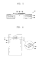
- FIG. 5 is a sectional view taken along line 'V-V' in FIG. 2
- FIG. 6 is a conceptual view showing a front surface of a battery cover according to one embodiment of the present disclosure
- FIG. 7 is a rear view of FIG. 6
- FIG. 8 is a sectional view taken along line'VII-VII' in FIG. 6 .
- the cover 260 according to one embodiment of the present disclosure may be applied to parts where the battery cover 190, the key 131 or the cameras 121, 121' are arranged.
- the cover 260 may be also applied to any part of a case which constitutes the appearance of the portable terminal 100.
- the cover 260 of the portable terminal 100 includes a metallic layer 261, a second metallic layer 262, and an exposed portion 264.
- the second metallic layer 262 may be laminated on the first metallic layer 261, or the first metallic layer 261 may be laminated on the second metallic layer 262.
- the reason why hetero metallic layers are laminated on each other is in order to implement a sophisticated appearance of the portable terminal by forming a unique pattern on the case which constitutes the appearance of the portable terminal 100. Accordingly, the present disclosure may provide a case having no restrictions in a material or a shape.
- the cover of the portable terminal When the cover of the portable terminal is formed of stainless steel (STS) or titanium (Ti), it is generally easy to perform a welding processing with respect to hooks coupled to the terminal body, or a press-processing for forming a predetermined pattern. However, in this case, it is difficult to implement various colors or designs. On the contrary, when the cover of the portable terminal is formed of aluminum, copper or magnesium alloy, it is possible to implement a sophisticated color or design through anodizing. However, it is difficult to perform a welding process with respect to hooks, and an intensity of the case is lowered.
- the present disclosure provides a cover of a portable terminal having no restrictions.
- the second metallic layer 262 may be formed of titanium or stainless steel. This may strengthen an intensity of the cover, and may weld hook portions 282 to the second metallic layer 262.
- the first metallic layer 261 is formed with using titanium or stainless steel through a press-processing and a numerical control processing
- the second metallic layer 262 formed of aluminum, etc. may be exposed to the outside. And, the exposed surface undergoes an anodizing process to form a molding layer 265, thereby implementing a specific pattern or logo. In this case, as shown in FIG.
- one end of the second metallic layer 262, an end portion of a side surface of the battery cover coupled to the terminal body is removed. Then, the hook portions 282 are formed on the first metallic layer by welding. As shown in FIG. 3 , the battery cover may be detachably coupled to a locking portion 282'.
- the exposed portion 264 is formed by removing the first metallic layer 261 laminated on the protruding pattern.
- the first metallic layer 261 and the second metallic layer 262 are protruding by a press-processing, and a through hole 263 is formed at the first metallic layer 261 by removing the first metallic layer 261.
- the exposed portion 264 is formed as a part of the second metallic layer 262 is extending via the through hole 263 by receiving a pressure due to a press-processing.
- FIG. 9 is a conceptual view showing a front surface of a battery cover according to another embodiment of the present disclosure
- FIG. 10 is a sectional view taken along line 'VIII-VIII' in FIG. 9 .
- one surface of the battery cover is protruding by being pressed, and then the first metallic layer is removed to form the exposed portion. Then, the molding layer corresponding to a logo may be formed by etching.
- the second metallic layer 262 is formed of stainless steel or titanium. This may reduce lowering of a radiation efficiency of the antenna.
- arranging the cover 260 so as to overlap an antenna of the portable terminal 100 indicates covering a space where the antenna is accommodated with using the battery cover 190.
- FIG. 11 is a sectional view taken along line 'IV-IV' in FIG. 2
- FIG. 12 is a planar view of FIG. 11 .
- the cover 260 may implement keys together with a key body 268.
- This key is provided with hetero metallic layers to implement a unique appearance.
- the key is inserted into an insertion hole 271 formed at the terminal body so that at least one surface thereof can be exposed to the outside.
- the cover 260 may be attached to the key body 268, and the exposed portion 264 of the cover 260 may be protruding from the first metallic layer 261 by a predetermined gap.
- An optical source 269 such as an LED may be formed around the key. Under this configuration, light from the optical source 269 is leaked to a minute gap between the key and the case of the portable terminal, thereby enhancing a user's manipulation and providing sophisticated feeling of the portable terminal.
- a key mark 266 relating to functions of the portable terminal may be formed at the cover 260 in a predetermined pattern.
- FIG. 13 is a sectional view taken along line'VI-VI' in FIG. 2 .
- the cover 260 may be used as a part of a camera housing at a position where the camera 280 of the portable terminal 100 is arranged, so as to prevent lowering of a function of the camera 280 due to reflection of light, diffraction, etc. on a camera lens 281. That is, a color of the exposed portion 264 is anodized so as to reduce reflection or light.
- the exposed portion 264 is formed to include a second through hole 267, and a lens is arranged at the second through hole 267.
Landscapes
- Engineering & Computer Science (AREA)
- Signal Processing (AREA)
- Microelectronics & Electronic Packaging (AREA)
- Telephone Set Structure (AREA)
- Casings For Electric Apparatus (AREA)
Applications Claiming Priority (1)
| Application Number | Priority Date | Filing Date | Title |
|---|---|---|---|
| KR1020100114052A KR101803871B1 (ko) | 2010-11-16 | 2010-11-16 | 이동 단말기 및 그 제조방법 |
Publications (3)
| Publication Number | Publication Date |
|---|---|
| EP2453635A2 true EP2453635A2 (de) | 2012-05-16 |
| EP2453635A3 EP2453635A3 (de) | 2014-07-02 |
| EP2453635B1 EP2453635B1 (de) | 2017-03-08 |
Family
ID=45470758
Family Applications (1)
| Application Number | Title | Priority Date | Filing Date |
|---|---|---|---|
| EP11005475.6A Not-in-force EP2453635B1 (de) | 2010-11-16 | 2011-07-05 | Tragbares Endgerät und Verfahren zu dessen Herstellung |
Country Status (4)
| Country | Link |
|---|---|
| US (1) | US8675358B2 (de) |
| EP (1) | EP2453635B1 (de) |
| KR (1) | KR101803871B1 (de) |
| CN (1) | CN102469182B (de) |
Cited By (2)
| Publication number | Priority date | Publication date | Assignee | Title |
|---|---|---|---|---|
| CN109905503A (zh) * | 2019-02-28 | 2019-06-18 | Oppo广东移动通信有限公司 | 壳体、电子装置以及制备壳体的方法 |
| CN113829003A (zh) * | 2020-06-23 | 2021-12-24 | 宏碁股份有限公司 | 机壳及其制作方法 |
Families Citing this family (13)
| Publication number | Priority date | Publication date | Assignee | Title |
|---|---|---|---|---|
| US9001507B2 (en) * | 2012-01-17 | 2015-04-07 | Lg Electronics Inc. | Mobile terminal |
| US20170226654A1 (en) * | 2014-10-27 | 2017-08-10 | Hewlett-Packard Development Company, L.P. | Magnesium alloy substrate |
| KR102362530B1 (ko) * | 2014-11-20 | 2022-02-15 | 엘지전자 주식회사 | 전자 디바이스 |
| CN105530785B (zh) * | 2014-12-26 | 2016-11-23 | 比亚迪股份有限公司 | 一种形成有天线槽的电子产品金属壳体及其制备方法 |
| CN106163162A (zh) * | 2015-03-30 | 2016-11-23 | 富泰华精密电子(郑州)有限公司 | 电子设备的壳体 |
| KR101720116B1 (ko) * | 2015-11-02 | 2017-04-06 | 주식회사 세원하이텍 | 안경테, 스마트폰 외장재 등 다중 금속 구조물의 표면처리방법, 이를 통해 제작된 안경테 및 스마트폰 외장재 |
| CN106657505B (zh) * | 2017-02-09 | 2023-08-18 | 深圳市欢太科技有限公司 | 终端的壳体及终端 |
| CN106713568A (zh) * | 2017-02-09 | 2017-05-24 | 广东欧珀移动通信有限公司 | 终端、终端的壳体及壳体的制造方法 |
| WO2018209520A1 (zh) * | 2017-05-15 | 2018-11-22 | 广东欧珀移动通信有限公司 | 复合金属板材、用于电子设备的壳体以及电子设备 |
| US11296404B2 (en) * | 2017-12-12 | 2022-04-05 | Universal City Studios Llc | Radio frequency enabled thematic interface systems and methods |
| WO2019191300A1 (en) * | 2018-03-28 | 2019-10-03 | Corning Incorporated | Laminated glass structures for electronic devices and electronic device covers |
| KR102750805B1 (ko) * | 2020-06-23 | 2025-01-08 | 삼성전자주식회사 | 금속 물질을 포함하는 하우징을 갖는 전자 장치 |
| JP2022108863A (ja) * | 2021-01-14 | 2022-07-27 | レノボ・シンガポール・プライベート・リミテッド | 情報機器およびカバー |
Family Cites Families (23)
| Publication number | Priority date | Publication date | Assignee | Title |
|---|---|---|---|---|
| US5318108A (en) * | 1988-04-15 | 1994-06-07 | Midwest Research Institute | Gas-controlled dynamic vacuum insulation with gas gate |
| US6752946B2 (en) * | 1996-09-27 | 2004-06-22 | Nissha Printing Co., Ltd. | Cellular phone top cover and method of manufacturing the cellular phone top cover |
| KR100384993B1 (ko) * | 2001-05-22 | 2003-05-23 | 주식회사 유일전자 | 이엘램프 내장 일체형 키패드 |
| KR100404102B1 (ko) * | 2001-09-04 | 2003-11-03 | 엘지전자 주식회사 | 휴대단말기의 키패드 백라이팅 장치 |
| JP3900063B2 (ja) | 2002-10-30 | 2007-04-04 | 株式会社デンソー | 携帯機のケース |
| DE10258209A1 (de) * | 2002-12-12 | 2004-06-24 | Siemens Ag | Eingabevorrichtung, insbesondere für ein Mobiltelefon, Modul mit einer Eingabevorrichtung und Verfahren zur Herstellung |
| TWI231135B (en) * | 2003-08-08 | 2005-04-11 | Hon Hai Prec Ind Co Ltd | Keypad and mobile phone employing the same |
| JP4556174B2 (ja) * | 2004-12-15 | 2010-10-06 | 日本電気株式会社 | 携帯端末機器及び放熱方法 |
| US8024016B2 (en) * | 2006-07-18 | 2011-09-20 | Lg Electronics Inc. | Portable electronic device |
| KR101168937B1 (ko) * | 2006-07-18 | 2012-08-02 | 엘지전자 주식회사 | 휴대 단말기 |
| JPWO2008035736A1 (ja) * | 2006-09-22 | 2010-01-28 | 日本写真印刷株式会社 | ハウジングケースと、当該ハウジングケースの製造方法とこれに用いるガラスインサート成形用金型 |
| WO2008053859A1 (fr) * | 2006-10-30 | 2008-05-08 | Kyocera Corporation | Appareil radio portable |
| CN100569535C (zh) | 2006-12-05 | 2009-12-16 | 微星科技股份有限公司 | 图样成形方法及使用该方法制作的笔记本电脑壳体 |
| WO2008122296A1 (en) * | 2007-04-04 | 2008-10-16 | Nokia Corporation | Casing assembly |
| TWI383786B (zh) * | 2007-05-04 | 2013-02-01 | Chi Mei Comm Systems Inc | 攜帶式電子裝置 |
| JP2009061730A (ja) * | 2007-09-07 | 2009-03-26 | Fujitsu Component Ltd | 装飾筐体及びその製造方法 |
| CN101420829B (zh) * | 2007-10-25 | 2011-09-21 | 深圳富泰宏精密工业有限公司 | 金属外壳及其制作方法 |
| CN101417522B (zh) * | 2007-10-25 | 2012-05-02 | 鸿富锦精密工业(深圳)有限公司 | 壳体及表面处理方法 |
| CN101497251A (zh) | 2008-02-01 | 2009-08-05 | 深圳富泰宏精密工业有限公司 | 壳体 |
| CN201312452Y (zh) * | 2008-10-31 | 2009-09-16 | 比亚迪股份有限公司 | 一种电子产品外壳及其电子产品 |
| DE202009006513U1 (de) * | 2009-05-05 | 2009-10-01 | Gadalla, Martin | Abdeckung, Individualisierungsmittel sowie Schmuck- und/oder Schutzeinrichtung für mobile Multimedia- oder andere elektronische Endgeräte wie insbesondere Mobiltelefone |
| CN102069672B (zh) * | 2009-11-20 | 2013-12-25 | 深圳富泰宏精密工业有限公司 | 装饰性外壳的制作方法 |
| US8618415B2 (en) * | 2010-10-22 | 2013-12-31 | Blackberry Limited | Portable electronic device and method of manufacturing parts thereof |
-
2010
- 2010-11-16 KR KR1020100114052A patent/KR101803871B1/ko not_active Expired - Fee Related
-
2011
- 2011-06-16 US US13/161,654 patent/US8675358B2/en not_active Expired - Fee Related
- 2011-07-05 EP EP11005475.6A patent/EP2453635B1/de not_active Not-in-force
- 2011-08-01 CN CN201110220243.2A patent/CN102469182B/zh not_active Expired - Fee Related
Non-Patent Citations (1)
| Title |
|---|
| None |
Cited By (3)
| Publication number | Priority date | Publication date | Assignee | Title |
|---|---|---|---|---|
| CN109905503A (zh) * | 2019-02-28 | 2019-06-18 | Oppo广东移动通信有限公司 | 壳体、电子装置以及制备壳体的方法 |
| CN113829003A (zh) * | 2020-06-23 | 2021-12-24 | 宏碁股份有限公司 | 机壳及其制作方法 |
| CN113829003B (zh) * | 2020-06-23 | 2022-12-27 | 宏碁股份有限公司 | 机壳的制作方法 |
Also Published As
| Publication number | Publication date |
|---|---|
| KR101803871B1 (ko) | 2017-12-04 |
| US8675358B2 (en) | 2014-03-18 |
| EP2453635A3 (de) | 2014-07-02 |
| CN102469182B (zh) | 2014-10-15 |
| CN102469182A (zh) | 2012-05-23 |
| EP2453635B1 (de) | 2017-03-08 |
| KR20120052758A (ko) | 2012-05-24 |
| US20120120570A1 (en) | 2012-05-17 |
Similar Documents
| Publication | Publication Date | Title |
|---|---|---|
| US8675358B2 (en) | Portable terminal and method for manufacturing the same | |
| KR101736862B1 (ko) | 이동 단말기의 케이스, 이를 구비하는 이동 단말기 및 이동 단말기의 케이스 제조 방법 | |
| KR101545573B1 (ko) | 휴대 단말기용 케이스 제조 방법 | |
| KR101580126B1 (ko) | 이동 단말기 | |
| KR101917681B1 (ko) | 이동 단말기 및 이의 케이스 제조 방법 | |
| US8095180B2 (en) | Mobile terminal | |
| KR20120108827A (ko) | 인쇄회로기판 어셈블리, 이의 제조 방법 및 이를 구비하는 이동 단말기 | |
| KR20130012521A (ko) | 이동 단말기 | |
| US10652374B2 (en) | Mobile terminal having case, method for manufacturing same | |
| CN102110882A (zh) | 天线装置和具有该天线装置的便携式终端 | |
| US20140323185A1 (en) | Mobile terminal and method of manufacturing a case included in the mobile terminal | |
| KR20140025916A (ko) | 이동 단말기 및 이동 단말기의 케이스 제조 방법 | |
| US9291827B2 (en) | Mobile terminal and method for fabricating image module provided thereon | |
| KR101659024B1 (ko) | 이동 단말기 | |
| CN102387227B (zh) | 便携式终端 | |
| KR101578799B1 (ko) | 케이싱 및 이를 구비하는 휴대 단말기 | |
| KR101869771B1 (ko) | 이동 단말기 및 이동 단말기의 키 패드 제조방법 | |
| KR101441922B1 (ko) | 터치 센서 조립체 및 이를 구비하는 휴대 단말기 | |
| KR20100131828A (ko) | 휴대용 단말기 | |
| KR101721875B1 (ko) | 이동 단말기 및 이동 단말기의 제조방법 | |
| KR101604749B1 (ko) | 휴대 단말기 및 휴대 단말기용 케이스의 제조방법 | |
| KR101463825B1 (ko) | 휴대 단말기 | |
| KR101960513B1 (ko) | 이동 단말기 | |
| KR101604714B1 (ko) | 휴대 단말기 | |
| KR101595362B1 (ko) | 휴대 단말기 |
Legal Events
| Date | Code | Title | Description |
|---|---|---|---|
| PUAI | Public reference made under article 153(3) epc to a published international application that has entered the european phase |
Free format text: ORIGINAL CODE: 0009012 |
|
| 17P | Request for examination filed |
Effective date: 20110706 |
|
| AK | Designated contracting states |
Kind code of ref document: A2 Designated state(s): AL AT BE BG CH CY CZ DE DK EE ES FI FR GB GR HR HU IE IS IT LI LT LU LV MC MK MT NL NO PL PT RO RS SE SI SK SM TR |
|
| AX | Request for extension of the european patent |
Extension state: BA ME |
|
| RIC1 | Information provided on ipc code assigned before grant |
Ipc: B44C 3/10 20060101ALI20140401BHEP Ipc: H04M 1/02 20060101AFI20140401BHEP |
|
| PUAL | Search report despatched |
Free format text: ORIGINAL CODE: 0009013 |
|
| AK | Designated contracting states |
Kind code of ref document: A3 Designated state(s): AL AT BE BG CH CY CZ DE DK EE ES FI FR GB GR HR HU IE IS IT LI LT LU LV MC MK MT NL NO PL PT RO RS SE SI SK SM TR |
|
| AX | Request for extension of the european patent |
Extension state: BA ME |
|
| RIC1 | Information provided on ipc code assigned before grant |
Ipc: B44C 3/10 20060101ALI20140528BHEP Ipc: H04M 1/02 20060101AFI20140528BHEP |
|
| 17Q | First examination report despatched |
Effective date: 20150421 |
|
| GRAP | Despatch of communication of intention to grant a patent |
Free format text: ORIGINAL CODE: EPIDOSNIGR1 |
|
| INTG | Intention to grant announced |
Effective date: 20161005 |
|
| STAA | Information on the status of an ep patent application or granted ep patent |
Free format text: STATUS: GRANT OF PATENT IS INTENDED |
|
| GRAS | Grant fee paid |
Free format text: ORIGINAL CODE: EPIDOSNIGR3 |
|
| GRAA | (expected) grant |
Free format text: ORIGINAL CODE: 0009210 |
|
| STAA | Information on the status of an ep patent application or granted ep patent |
Free format text: STATUS: THE PATENT HAS BEEN GRANTED |
|
| AK | Designated contracting states |
Kind code of ref document: B1 Designated state(s): AL AT BE BG CH CY CZ DE DK EE ES FI FR GB GR HR HU IE IS IT LI LT LU LV MC MK MT NL NO PL PT RO RS SE SI SK SM TR |
|
| REG | Reference to a national code |
Ref country code: GB Ref legal event code: FG4D |
|
| REG | Reference to a national code |
Ref country code: CH Ref legal event code: EP Ref country code: AT Ref legal event code: REF Ref document number: 874464 Country of ref document: AT Kind code of ref document: T Effective date: 20170315 |
|
| REG | Reference to a national code |
Ref country code: IE Ref legal event code: FG4D |
|
| REG | Reference to a national code |
Ref country code: DE Ref legal event code: R096 Ref document number: 602011035614 Country of ref document: DE |
|
| REG | Reference to a national code |
Ref country code: FR Ref legal event code: PLFP Year of fee payment: 7 |
|
| REG | Reference to a national code |
Ref country code: LT Ref legal event code: MG4D |
|
| REG | Reference to a national code |
Ref country code: NL Ref legal event code: MP Effective date: 20170308 |
|
| PG25 | Lapsed in a contracting state [announced via postgrant information from national office to epo] |
Ref country code: LT Free format text: LAPSE BECAUSE OF FAILURE TO SUBMIT A TRANSLATION OF THE DESCRIPTION OR TO PAY THE FEE WITHIN THE PRESCRIBED TIME-LIMIT Effective date: 20170308 Ref country code: GR Free format text: LAPSE BECAUSE OF FAILURE TO SUBMIT A TRANSLATION OF THE DESCRIPTION OR TO PAY THE FEE WITHIN THE PRESCRIBED TIME-LIMIT Effective date: 20170609 Ref country code: HR Free format text: LAPSE BECAUSE OF FAILURE TO SUBMIT A TRANSLATION OF THE DESCRIPTION OR TO PAY THE FEE WITHIN THE PRESCRIBED TIME-LIMIT Effective date: 20170308 Ref country code: NO Free format text: LAPSE BECAUSE OF FAILURE TO SUBMIT A TRANSLATION OF THE DESCRIPTION OR TO PAY THE FEE WITHIN THE PRESCRIBED TIME-LIMIT Effective date: 20170608 Ref country code: FI Free format text: LAPSE BECAUSE OF FAILURE TO SUBMIT A TRANSLATION OF THE DESCRIPTION OR TO PAY THE FEE WITHIN THE PRESCRIBED TIME-LIMIT Effective date: 20170308 |
|
| REG | Reference to a national code |
Ref country code: AT Ref legal event code: MK05 Ref document number: 874464 Country of ref document: AT Kind code of ref document: T Effective date: 20170308 |
|
| PG25 | Lapsed in a contracting state [announced via postgrant information from national office to epo] |
Ref country code: RS Free format text: LAPSE BECAUSE OF FAILURE TO SUBMIT A TRANSLATION OF THE DESCRIPTION OR TO PAY THE FEE WITHIN THE PRESCRIBED TIME-LIMIT Effective date: 20170308 Ref country code: BG Free format text: LAPSE BECAUSE OF FAILURE TO SUBMIT A TRANSLATION OF THE DESCRIPTION OR TO PAY THE FEE WITHIN THE PRESCRIBED TIME-LIMIT Effective date: 20170608 Ref country code: ES Free format text: LAPSE BECAUSE OF FAILURE TO SUBMIT A TRANSLATION OF THE DESCRIPTION OR TO PAY THE FEE WITHIN THE PRESCRIBED TIME-LIMIT Effective date: 20170308 Ref country code: LV Free format text: LAPSE BECAUSE OF FAILURE TO SUBMIT A TRANSLATION OF THE DESCRIPTION OR TO PAY THE FEE WITHIN THE PRESCRIBED TIME-LIMIT Effective date: 20170308 Ref country code: SE Free format text: LAPSE BECAUSE OF FAILURE TO SUBMIT A TRANSLATION OF THE DESCRIPTION OR TO PAY THE FEE WITHIN THE PRESCRIBED TIME-LIMIT Effective date: 20170308 |
|
| PG25 | Lapsed in a contracting state [announced via postgrant information from national office to epo] |
Ref country code: NL Free format text: LAPSE BECAUSE OF FAILURE TO SUBMIT A TRANSLATION OF THE DESCRIPTION OR TO PAY THE FEE WITHIN THE PRESCRIBED TIME-LIMIT Effective date: 20170308 |
|
| PG25 | Lapsed in a contracting state [announced via postgrant information from national office to epo] |
Ref country code: RO Free format text: LAPSE BECAUSE OF FAILURE TO SUBMIT A TRANSLATION OF THE DESCRIPTION OR TO PAY THE FEE WITHIN THE PRESCRIBED TIME-LIMIT Effective date: 20170308 Ref country code: CZ Free format text: LAPSE BECAUSE OF FAILURE TO SUBMIT A TRANSLATION OF THE DESCRIPTION OR TO PAY THE FEE WITHIN THE PRESCRIBED TIME-LIMIT Effective date: 20170308 Ref country code: SK Free format text: LAPSE BECAUSE OF FAILURE TO SUBMIT A TRANSLATION OF THE DESCRIPTION OR TO PAY THE FEE WITHIN THE PRESCRIBED TIME-LIMIT Effective date: 20170308 Ref country code: IT Free format text: LAPSE BECAUSE OF FAILURE TO SUBMIT A TRANSLATION OF THE DESCRIPTION OR TO PAY THE FEE WITHIN THE PRESCRIBED TIME-LIMIT Effective date: 20170308 Ref country code: AT Free format text: LAPSE BECAUSE OF FAILURE TO SUBMIT A TRANSLATION OF THE DESCRIPTION OR TO PAY THE FEE WITHIN THE PRESCRIBED TIME-LIMIT Effective date: 20170308 Ref country code: EE Free format text: LAPSE BECAUSE OF FAILURE TO SUBMIT A TRANSLATION OF THE DESCRIPTION OR TO PAY THE FEE WITHIN THE PRESCRIBED TIME-LIMIT Effective date: 20170308 |
|
| PG25 | Lapsed in a contracting state [announced via postgrant information from national office to epo] |
Ref country code: IS Free format text: LAPSE BECAUSE OF FAILURE TO SUBMIT A TRANSLATION OF THE DESCRIPTION OR TO PAY THE FEE WITHIN THE PRESCRIBED TIME-LIMIT Effective date: 20170708 Ref country code: PT Free format text: LAPSE BECAUSE OF FAILURE TO SUBMIT A TRANSLATION OF THE DESCRIPTION OR TO PAY THE FEE WITHIN THE PRESCRIBED TIME-LIMIT Effective date: 20170710 Ref country code: PL Free format text: LAPSE BECAUSE OF FAILURE TO SUBMIT A TRANSLATION OF THE DESCRIPTION OR TO PAY THE FEE WITHIN THE PRESCRIBED TIME-LIMIT Effective date: 20170308 Ref country code: SM Free format text: LAPSE BECAUSE OF FAILURE TO SUBMIT A TRANSLATION OF THE DESCRIPTION OR TO PAY THE FEE WITHIN THE PRESCRIBED TIME-LIMIT Effective date: 20170308 |
|
| REG | Reference to a national code |
Ref country code: DE Ref legal event code: R097 Ref document number: 602011035614 Country of ref document: DE |
|
| PLBE | No opposition filed within time limit |
Free format text: ORIGINAL CODE: 0009261 |
|
| STAA | Information on the status of an ep patent application or granted ep patent |
Free format text: STATUS: NO OPPOSITION FILED WITHIN TIME LIMIT |
|
| PG25 | Lapsed in a contracting state [announced via postgrant information from national office to epo] |
Ref country code: DK Free format text: LAPSE BECAUSE OF FAILURE TO SUBMIT A TRANSLATION OF THE DESCRIPTION OR TO PAY THE FEE WITHIN THE PRESCRIBED TIME-LIMIT Effective date: 20170308 |
|
| 26N | No opposition filed |
Effective date: 20171211 |
|
| PG25 | Lapsed in a contracting state [announced via postgrant information from national office to epo] |
Ref country code: SI Free format text: LAPSE BECAUSE OF FAILURE TO SUBMIT A TRANSLATION OF THE DESCRIPTION OR TO PAY THE FEE WITHIN THE PRESCRIBED TIME-LIMIT Effective date: 20170308 |
|
| REG | Reference to a national code |
Ref country code: CH Ref legal event code: PL |
|
| REG | Reference to a national code |
Ref country code: IE Ref legal event code: MM4A |
|
| PG25 | Lapsed in a contracting state [announced via postgrant information from national office to epo] |
Ref country code: CH Free format text: LAPSE BECAUSE OF NON-PAYMENT OF DUE FEES Effective date: 20170731 Ref country code: IE Free format text: LAPSE BECAUSE OF NON-PAYMENT OF DUE FEES Effective date: 20170705 Ref country code: LI Free format text: LAPSE BECAUSE OF NON-PAYMENT OF DUE FEES Effective date: 20170731 |
|
| REG | Reference to a national code |
Ref country code: BE Ref legal event code: MM Effective date: 20170731 |
|
| REG | Reference to a national code |
Ref country code: FR Ref legal event code: PLFP Year of fee payment: 8 |
|
| PG25 | Lapsed in a contracting state [announced via postgrant information from national office to epo] |
Ref country code: LU Free format text: LAPSE BECAUSE OF NON-PAYMENT OF DUE FEES Effective date: 20170705 |
|
| PG25 | Lapsed in a contracting state [announced via postgrant information from national office to epo] |
Ref country code: BE Free format text: LAPSE BECAUSE OF NON-PAYMENT OF DUE FEES Effective date: 20170731 |
|
| PG25 | Lapsed in a contracting state [announced via postgrant information from national office to epo] |
Ref country code: MT Free format text: LAPSE BECAUSE OF NON-PAYMENT OF DUE FEES Effective date: 20170705 |
|
| PGFP | Annual fee paid to national office [announced via postgrant information from national office to epo] |
Ref country code: GB Payment date: 20180606 Year of fee payment: 8 Ref country code: DE Payment date: 20180605 Year of fee payment: 8 |
|
| PG25 | Lapsed in a contracting state [announced via postgrant information from national office to epo] |
Ref country code: HU Free format text: LAPSE BECAUSE OF FAILURE TO SUBMIT A TRANSLATION OF THE DESCRIPTION OR TO PAY THE FEE WITHIN THE PRESCRIBED TIME-LIMIT; INVALID AB INITIO Effective date: 20110705 Ref country code: MC Free format text: LAPSE BECAUSE OF FAILURE TO SUBMIT A TRANSLATION OF THE DESCRIPTION OR TO PAY THE FEE WITHIN THE PRESCRIBED TIME-LIMIT Effective date: 20170308 |
|
| PGFP | Annual fee paid to national office [announced via postgrant information from national office to epo] |
Ref country code: FR Payment date: 20190605 Year of fee payment: 9 |
|
| PG25 | Lapsed in a contracting state [announced via postgrant information from national office to epo] |
Ref country code: CY Free format text: LAPSE BECAUSE OF NON-PAYMENT OF DUE FEES Effective date: 20170308 |
|
| PG25 | Lapsed in a contracting state [announced via postgrant information from national office to epo] |
Ref country code: MK Free format text: LAPSE BECAUSE OF FAILURE TO SUBMIT A TRANSLATION OF THE DESCRIPTION OR TO PAY THE FEE WITHIN THE PRESCRIBED TIME-LIMIT Effective date: 20170308 |
|
| REG | Reference to a national code |
Ref country code: DE Ref legal event code: R119 Ref document number: 602011035614 Country of ref document: DE |
|
| GBPC | Gb: european patent ceased through non-payment of renewal fee |
Effective date: 20190705 |
|
| PG25 | Lapsed in a contracting state [announced via postgrant information from national office to epo] |
Ref country code: TR Free format text: LAPSE BECAUSE OF FAILURE TO SUBMIT A TRANSLATION OF THE DESCRIPTION OR TO PAY THE FEE WITHIN THE PRESCRIBED TIME-LIMIT Effective date: 20170308 |
|
| PG25 | Lapsed in a contracting state [announced via postgrant information from national office to epo] |
Ref country code: DE Free format text: LAPSE BECAUSE OF NON-PAYMENT OF DUE FEES Effective date: 20200201 Ref country code: GB Free format text: LAPSE BECAUSE OF NON-PAYMENT OF DUE FEES Effective date: 20190705 |
|
| PG25 | Lapsed in a contracting state [announced via postgrant information from national office to epo] |
Ref country code: AL Free format text: LAPSE BECAUSE OF FAILURE TO SUBMIT A TRANSLATION OF THE DESCRIPTION OR TO PAY THE FEE WITHIN THE PRESCRIBED TIME-LIMIT Effective date: 20170308 |
|
| PG25 | Lapsed in a contracting state [announced via postgrant information from national office to epo] |
Ref country code: FR Free format text: LAPSE BECAUSE OF NON-PAYMENT OF DUE FEES Effective date: 20200731 |