EP2453262B1 - Positionsinformationserkennungsvorrichtung - Google Patents
Positionsinformationserkennungsvorrichtung Download PDFInfo
- Publication number
- EP2453262B1 EP2453262B1 EP11187072.1A EP11187072A EP2453262B1 EP 2453262 B1 EP2453262 B1 EP 2453262B1 EP 11187072 A EP11187072 A EP 11187072A EP 2453262 B1 EP2453262 B1 EP 2453262B1
- Authority
- EP
- European Patent Office
- Prior art keywords
- position information
- unit
- obtaining unit
- information obtaining
- monitor cycle
- Prior art date
- Legal status (The legal status is an assumption and is not a legal conclusion. Google has not performed a legal analysis and makes no representation as to the accuracy of the status listed.)
- Active
Links
Images


Classifications
-
- G—PHYSICS
- G01—MEASURING; TESTING
- G01S—RADIO DIRECTION-FINDING; RADIO NAVIGATION; DETERMINING DISTANCE OR VELOCITY BY USE OF RADIO WAVES; LOCATING OR PRESENCE-DETECTING BY USE OF THE REFLECTION OR RERADIATION OF RADIO WAVES; ANALOGOUS ARRANGEMENTS USING OTHER WAVES
- G01S19/00—Satellite radio beacon positioning systems; Determining position, velocity or attitude using signals transmitted by such systems
- G01S19/38—Determining a navigation solution using signals transmitted by a satellite radio beacon positioning system
- G01S19/39—Determining a navigation solution using signals transmitted by a satellite radio beacon positioning system the satellite radio beacon positioning system transmitting time-stamped messages, e.g. GPS [Global Positioning System], GLONASS [Global Orbiting Navigation Satellite System] or GALILEO
- G01S19/42—Determining position
- G01S19/48—Determining position by combining or switching between position solutions derived from the satellite radio beacon positioning system and position solutions derived from a further system
-
- G—PHYSICS
- G01—MEASURING; TESTING
- G01S—RADIO DIRECTION-FINDING; RADIO NAVIGATION; DETERMINING DISTANCE OR VELOCITY BY USE OF RADIO WAVES; LOCATING OR PRESENCE-DETECTING BY USE OF THE REFLECTION OR RERADIATION OF RADIO WAVES; ANALOGOUS ARRANGEMENTS USING OTHER WAVES
- G01S19/00—Satellite radio beacon positioning systems; Determining position, velocity or attitude using signals transmitted by such systems
- G01S19/01—Satellite radio beacon positioning systems transmitting time-stamped messages, e.g. GPS [Global Positioning System], GLONASS [Global Orbiting Navigation Satellite System] or GALILEO
- G01S19/13—Receivers
- G01S19/34—Power consumption
-
- G—PHYSICS
- G01—MEASURING; TESTING
- G01S—RADIO DIRECTION-FINDING; RADIO NAVIGATION; DETERMINING DISTANCE OR VELOCITY BY USE OF RADIO WAVES; LOCATING OR PRESENCE-DETECTING BY USE OF THE REFLECTION OR RERADIATION OF RADIO WAVES; ANALOGOUS ARRANGEMENTS USING OTHER WAVES
- G01S5/00—Position-fixing by co-ordinating two or more direction or position line determinations; Position-fixing by co-ordinating two or more distance determinations
- G01S5/01—Determining conditions which influence positioning, e.g. radio environment, state of motion or energy consumption
- G01S5/017—Detecting state or type of motion
Definitions
- the present disclosure relates to a position information detection device applicable to a battery-driven terminal such as, for example, a mobile phone
- the disclosure relates to a position information detection device, performing hybrid positioning by combining GPS position information and position information based on information obtained from a plurality of peripheral base stations.
- the wireless network side has also enlarged, and, for example, in the 3GPP system, a HAPA+ service which realizes a maximum of 21 Mbps has started, and, in the IEEE system, a Mobile WiMAX service to realize a maximum of 40 Mbps has started.
- an LTE (Long Term Evolution) service which uses OFDMA (Orthogonal Frequency Division Multiple Access) in the downlink in a manner similar to the Mobile WiMAX (Worldwide Interoperability for Microwave Access), is scheduled to start in the latter half of the year 2010, and a 4G (LTE-Advanced) service is also scheduled to start around the year 2015. From the start of the services, it is expected that a maximum of 1 Gbps will be realized in semifixed circumstances, and a maximum of 100 Mbps will be realized even in movement circumstances.
- OFDMA Orthogonal Frequency Division Multiple Access
- the GPS receiver can obtain position information with relatively high accuracy of several meters to several tens of meters in circumstances where signals are able to be received from a GPS satellite.
- a portable terminal which is driven by a battery such as a mobile phone is sensitive to power consumption, and thus there is a problem in that it is difficult to obtain position information by operating the GPS receiver at all times.
- a position information measurement system in which a server side receives a current position from a GPS terminal and designates a position where the next position is measured on a movement route of the GPS terminal, the GPS terminal calculates a movement time from the current position to the position where the next position is measured, and the GPS terminal stops the position measurement operation for the movement time (for example, refer to Japanese Patent Application Publication No. 2005-337855 ). Since the GPS terminal stops the movement measurement operation for the calculated movement time, power consumption can be reduced. However, it is difficult to apply the system to a target of which a movement route is not identified.
- a portable terminal such as a mobile phone is used in a place where a GPS signal is not able to be received such as an indoor location or a basement in many cases, it is preferable to obtain position information with as high accuracy as possible in various circumstances by including position information obtaining functions in addition to the GPS receiver.
- the public wireless base station since the public wireless base station has a wide coverage, it is possible to measure a current position even in a place where a GPS signal is not able to be received such as an indoor location or a basement.
- the base stations are arranged with the units of several kilometers, and thus there is a problem in that the technique has accuracy lower than the GPS.
- hybrid positioning where positioning is performed by combining position estimations using both position information estimated from Wi-Fi electric measurement information and GPS position information. According to the hybrid positioning, a position can be estimated from Wi-Fi electric measurement information at an indoor location where the GPS is not able to be used, and a position can be obtained from the GPS at a place where Wi-Fi access points are not present in the vicinity.
- a receiver which receives a global positioning system (GPS) signal and a digital broadcasting system (DBS) signal, determines presence states and signal intensities of the GPS signal and the DBS signal via a signal detector of the receiver, selects one positioning mode from a plurality of positioning modes of a signal processing unit of the receiver based on the detected signal presence states and the signal intensities of the signals, and determines a position of the receiver based on the selected positioning mode (for example, refer to Japanese Patent Application Publication No. 2007-139772 ).
- GPS global positioning system
- DBS digital broadcasting system
- Prior art EP1,548,456A describes a subscriber unit for a cellular communication system which comprises a first location processor which determines a location estimate from signals transmitted from satellites and from satellite information related to the satellites.
- the subscriber unit also comprises a receiver which receives the satellite information, and further comprises a second location processor which determines location estimates based on uplink or downlink transmissions in the cellular communication system.
- An update controller determines an update time for the satellite information in response to the location estimates of the second location processor.
- Prior art US2007/241888A describes an energy constrained device includes a motion sensor operative to detect motion of the device; a device position determinator; and a controller operatively coupled to the motion sensor and to the device position determinator and operative to receive a device location request for the energy constrained device, to determine whether the energy constrained device has moved based on the motion sensor, and to determine whether to request position information from the device position determinator based on device movement.
- Prior art US2009/098880A describes a method for determining location of a mobile terminal includes repetitively switching power-on and power-off to a GPS receiver circuit which determines location of the mobile terminal using GPS signals.
- the power-on to power-off duty cycle of the GPS receiver circuit is regulated in response to distance that the mobile terminal has moved from a previously determined location.
- Prior art US2009/192709A describes an electronic device which may be configured to select between a plurality of position sources to determine position based upon a variety of selection criteria.
- a last known position may be stored when position is being determined through the plurality of position sources. The last known position may be used as an alternative to determining position via the position sources when one or more of the position sources are unavailable.
- GB2400525A and EP1,443,791A each describe prior art devices.
- Fig. 1 schematically shows a configuration example of a communication system.
- methods for trying to access a plurality of telecommunications carriers are introduced in managing a SIM (Subscriber Identity Module) of a portable wireless communication terminal device, or heterogeneous wireless circumstances where a plurality of wireless communication services are considered.
- SIM Subscriber Identity Module
- the shown communication system 100 includes a portable terminal 120, a plurality of first base stations 130A and 130B, a first core network 140, a plurality of second base stations 150A and 150B, and a second core network 160.
- the first core network 140 is a network of a telecommunications carrier for providing a first wireless communication service (for example, a 3G service), and is connected to a plurality of first base stations 130.
- the first core network 140 includes, for example, an MME (Mobile Management Entity) performing setting, opening, a control of handover of sessions for data communication, or the like, or a gateway controlling routing, transmission, or the like of user data.
- MME Mobile Management Entity
- the second core network 160 is a network of a telecommunications carrier for providing a second wireless communication service (for example, LTE, WiMAX, 4G, or the like), and is connected to a plurality of second base stations 150.
- the second core network 160 includes the MME or the gateway in the same manner as the first core network 140.
- the base stations such as the first base stations 130 and the second base stations 150 control communication with the portable terminal 120.
- the base stations relay data received from the portable terminal 120 so as to direct to a destination, and, if receiving data addressed to the portable terminal 120, transmits the data to the portable terminal 120.
- the base stations can communicate with the portable terminal 120 by employing a wireless multiple access method such as orthogonal frequency division multiple access (OFDMA), time division multiple access (TDMA), or code division multiple access (CDMA).
- OFDMA orthogonal frequency division multiple access
- TDMA time division multiple access
- CDMA code division multiple access
- the portable terminal 120 can perform communication of a variety of data with other devices via the first base stations 130 or the second base stations 150.
- the variety of data includes music data such as music, lectures, and radio programs, video data such as movies, television programs, video programs, photographs, documents, web pages, pictures, and charts, games, software, and the like.
- the wireless communication apparatus is not limited to the example.
- the wireless communication apparatus may be an information processing apparatus such as a PC (Personal Computer), a video processing device for households (a DVD recorder, a video deck, or the like), a PDA (Personal Digital Assistant), a household video game console, or an appliance.
- the wireless communication apparatus may be an information processing apparatus such as a mobile phone, a PHS (Personal Handyphone System), a portable music player, a portable video processing device, or a portable video game console.
- first base stations 130 and the second base stations 150 a variety of base stations such as macro cell base stations, relay nodes relaying communication between the macro cell base stations and the portable terminal 120, or household small-sized femtocells may be considered.
- Fig. 2 schematically shows an internal configuration example of the portable terminal 120 operated in the communication system shown in Fig. 1 .
- the respective parts thereof will be described.
- a CPU (Central Processing Unit) 201 executes application programs in execution circumstances provided by an operating system (OS), and controls the overall operations in the portable terminal 120.
- the application programs described here may include a variety of applications such as mail messaging and a browser, A detection frequency of an important degree of position information, in other words, necessary position information is diversified for each application program.
- a ROM (Read Only Memory) 202 permanently stores programs or operation parameters used by the CPU 201.
- a RAM (Random Access Memory) 203 is used as a work memory by loading a program to be used in execution of the CPU 201 thereto, or temporarily storing parameters which are appropriately varied.
- the CPU 201, the ROM 202, and the RAM 203 are connected to each other via a host bus 204 including a CPU bus or the like.
- the host bus 204 is further connected to an external bus 206 such as a PCI (Peripheral Component Interconnect/Interface) bus via a bridge 205.
- an external bus 206 such as a PCI (Peripheral Component Interconnect/Interface) bus via a bridge 205.
- the host bus 204, the bridge 205, and the external bus 206 are not necessarily configured separately from each other, but these functions may be mounted on a single bus.
- An input unit 208 includes an input portion used for a user to input information, such as a mouse, a keyboard, a touch panel, a button, a microphone, a switch, and a lever, and an input control circuit which generates an input signal based on an input by a user and outputs the input signal to the CPU 201.
- a user of the portable terminal 120 can input a variety of data to the portable terminal 120 or instruct process operations by operating the input unit 208.
- An output unit 210 includes a display device such as, for example, a liquid crystal display (LCD), an OLED (Organic Light Emitting Diode), and an LED. Further, the output unit 210 includes a voice output device such as a speaker and a headphone. The output unit 210 outputs, for example, reproduced content. Specifically, the display device displays and outputs a variety of information such as reproduced video data as texts or images. On the other hand, the voice output device converts reproduced voice data into voice and outputs the voice.
- a display device such as, for example, a liquid crystal display (LCD), an OLED (Organic Light Emitting Diode), and an LED.
- the output unit 210 includes a voice output device such as a speaker and a headphone.
- the output unit 210 outputs, for example, reproduced content. Specifically, the display device displays and outputs a variety of information such as reproduced video data as texts or images.
- the voice output device converts reproduced voice data into voice
- a storage 211 is a device for storing data and is an example of the storage unit of the portable terminal 120.
- the storage 211 may include a storage medium, a recording device recording data in the storage medium, a reading device reading data from the storage medium, and a deletion device deleting data recorded in the storage medium, and the like.
- the storage 211 may include, for example, a HDD (Hard Disk Drive), and install programs executed by the CPU 201 or store files of various kinds of data and the like, by driving a hard disk.
- HDD Hard Disk Drive
- a drive 212 is a reader and writer for a storage medium, and is embedded inside or attached outside the portable terminal 120.
- the drive 212 reads information recorded on a removable recording medium 214 such as a magnetic disk, an optical disc, a magneto-optical disc, or a semiconductor memory, and outputs the information to the RAM 203.
- the communication unit 215 is an interface for communication with external devices.
- the communication unit 215 may include a wireless communication function with the first base stations 130 and a wireless communication function with the second base stations 150.
- the communication unit 215 is assumed to correspond to a wireless multiple access method such as orthogonal frequency division multiple access (OFDMA), time division multiple access (TDMA) or code division multiple access (CDMA).
- OFDMA orthogonal frequency division multiple access
- TDMA time division multiple access
- CDMA code division multiple access
- the position information detection unit 216 detects information for a current position of the portable terminal 120.
- the position information detection unit 216 performs hybrid positioning by combining a plurality of position detection functions, such as a position detection function performed by a GPS receiver, and a position detection function of obtaining position information from information obtained via a plurality of public wireless base stations such as the first base stations 130 and the second base stations 150.
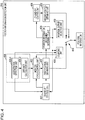
- Fig. 3 schematically shows an internal configuration example of the position information detection unit 216.
- the shown position information detection unit 216 includes a first position information obtaining unit 301, a second position information obtaining unit 302, a monitor cycle control unit 303, a movement detection unit 304, a counting unit 305, a position information obtainment determining unit 306, a first ON and OFF state control unit 307 which controls ON and OFF states of the first position information obtaining unit 301, a second ON and OFF state control unit 308 which controls ON and OFF states of the second position information obtaining unit 302, a position output selection unit 309, and a switch 310.
- the respective parts will be described.
- the first position information obtaining unit 301 is a functional module which receives a GPS signal and obtains high accuracy position information.
- the second position information obtaining unit 302 is a portion for obtaining position information even at a point where first position information obtaining unit 301 is not able to obtain a GPS signal. As described later, the first position information obtaining unit 301 and the second position information obtaining unit 302 are used in a complementary manner.
- the second position information obtaining unit 302 detects a reception level of a signal from a plurality of peripheral public wireless base stations (Wi-Fi access points or 3G base stations), and detects a propagation loss based on a difference with a transmission level.
- a distance to a base station which is a transmission source can be calculated based on the carrier frequency and the propagation loss, and thus position information for the second position information obtaining unit 302 can be calculated using position information for each public wireless base station and the distance from each public wireless base station.
- position information may be estimated by obtaining relative delay information of a signal from each public wireless base station.
- the present disclosure is not limited to the specific position obtaining functions of the second position information obtaining unit 302. It is important for the first position information obtaining unit 301 to differ from the second position information obtaining unit 302 in terms of accuracy of position obtainment and an area where a position can be obtained.
- the first position information obtaining unit 301 can obtain position information with high accuracy, but is not able to obtain position information in an area such as an indoor location or a basement (is not able to receive a GPS signal), and has high power consumption.
- the second position information obtaining unit 302 can obtain position information substantially in all areas, but has accuracy of position information which is not higher than the first position information obtaining unit 301.
- the monitor cycle control unit 303 controls a monitor cycle of the first position information obtaining unit 301, that is, a frequency where the first position information obtaining unit 301 obtains position information. If a monitor cycle is shortened, that is, an obtaining frequency of position information is increased, the first position information obtaining unit 301 frequently obtains high accuracy position information but power consumption is increased. On the other hand, if the monitor cycle is lengthened, that is, the obtaining frequency of position information is reduced, the first position information obtaining unit 301 has a decreasing opportunity for obtaining high accuracy position information, but power consumption can be reduced.
- the monitor cycle control unit 303 controls the monitor cycle based on outputs from the movement detection unit 304 and the counting unit 305.
- the movement detection unit 304 detects whether or not the position information detection unit 216 (or the first position information obtaining unit 301) is moved.
- the movement detection unit 304 detects that the first position information obtaining unit 301 is moved when there is a variation of a predetermined value or more in a position of the first position information obtaining unit 301. Further, if the movement detection unit 304 detects the movement of the first position information obtaining unit 301, the monitor cycle control unit 303 further shortens the monitor cycle such that the first position information obtaining unit 301 increases an obtaining frequency of position information. This is because a variation in a position is large and it is necessary to detect position information at a short cycle in frequent movement circumstances.
- the monitor cycle control unit 303 lengthens the monitor cycle such that the first position information obtaining unit 301 decreases the obtaining frequency of position information. This is because a variation in a position is small and position information can be obtained with sufficient accuracy even at a long cycle in infrequent movement circumstances.
- the counting unit 305 counts a time period where the movement detection unit 304 detects the movement of the position information detection unit 216. In addition, if the time period reaches a predetermined value (count 1), the monitor cycle control unit 303 returns the monitor cycle to a short monitor cycle such that the first position information obtaining unit 301 increases an obtaining frequency of position information again.
- the movement detection unit 304 detects the movement of the first position information obtaining unit 301 again, the monitor cycle of the first position information obtaining unit 301 is not promptly changed, but is changed after the counting unit 305 counts the specific time period (count 1). Therefore, the counting unit 305 plays a part in stabilizing the state transition by giving hysteresis to the transitioned state where the first position information obtaining unit 301 changes the obtaining frequency of position information.
- the position information obtainment determining unit 306 determines whether or not the first position information obtaining unit 301 obtains position information.
- the second ON and OFF state control unit 308 controls the second position information obtaining unit 302 to enter an ON state such that the second position information obtaining unit 302 starts an obtaining process of position information.
- the second position information obtaining unit 302 can supplement obtaining of position information in an area where the first position information obtaining unit 301 is not able to obtain position information.
- the counting unit 305 counts a time period where the position information obtainment determining unit 306 determines that the first position information obtaining unit 301 is not able to obtain position information.
- the monitor cycle control unit 303 controls a frequency where the first position information obtaining unit 301 obtains position information based on the time period. For example, if the first position information obtaining unit 301 is moved to a place where a GPS signal is not able to be received such as an indoor location or a basement, it is useless for the first position information obtaining unit 301 to frequently obtain position information despite not obtaining position information from the viewpoint of power consumption or the like.
- the movement detection unit 304 detects a movement of the first position information obtaining unit 301, further the counting unit 305 counts a time period where the first position information obtaining unit 301 is not able to obtain position information, and if the time period exceeds a predetermined value (count 2), the monitor cycle control unit 303 lengthens a monitor cycle so as to reduce an obtaining frequency of position information by the first position information obtaining unit 301.
- the counting unit 305 plays a part in stabilizing the state transition by giving a hysteresis to the transitioned state where the first position information obtaining unit 301 changes the obtaining frequency of position information.
- the first ON and OFF state control unit 307 controls the first position information obtaining unit 301 to enter an OFF state such that the obtaining process of position information stops.
- the first position information obtaining unit 301 is present at a place where a GPS signal is not able to be received such as an indoor location or a basement and also is not moved, position information is not able to be obtained using the GPS receiver. For this reason, power consumption is made to be reduced by stopping an operation of the GPS receiver in the above condition that the first position information obtaining unit 301 is not able to obtain position information and also is not moved.
- the first ON and OFF state control unit 307 controls the first position information obtaining unit 301 to enter an ON state such that the first position information obtaining unit 301 obtains position information again.
- the monitor cycle control unit 303 determines a monitor cycle when the first position information obtaining unit 301 resumes the position obtaining process. In the embodiment, a short monitor cycle is assumed to be set when the position obtaining process is resumed.
- the second ON and OFF state control unit 308 controls the second position information obtaining unit 302 to enter an OFF state so as to stop the position information obtaining process. This is because if higher accuracy position information can be obtained by the first position information obtaining unit 301, it is not necessary for the second position information obtaining unit 302 to obtain position information.
- the position output selection unit 309 determines which one of the first position information obtaining unit 301 and the second position information obtaining unit 302 obtains position information using the position information obtainment determining unit 306, and selects which one outputs the position information. In addition, when position information is obtained by both of the first position information obtaining unit 301 and the second position information obtaining unit 302, position information from the first position information obtaining unit 301 having higher accuracy is selected to be output. If the position information obtainment determining unit 306 determines that the first position information obtaining unit 301 obtains position information, the position output selection unit 309 may select an output from the first position information obtaining unit 301.
- the position output selection unit 309 may select an output from the second position information obtaining unit 302.
- accuracy of position information obtained by the first position information obtaining unit 301 may be higher than accuracy of position information obtained by the second position information obtaining unit 302 for a specific time period from a state where the first position information obtaining unit 301 obtains position information shortly after the first position information obtaining unit 301 is transitioned to a state of not obtaining position information.
- the position output selection unit 309 may output position information which is lastly obtained by the first position information obtaining unit 301 for the specific time period shortly after the first position information obtaining unit 301 is transitioned to a state of not obtaining position information.
- a length of the specific time period may be varied based on a movement distance detected by the movement detection unit 304.
- the switch 310 controls which position information of the first position information obtaining unit 301 and the second position information obtaining unit 302 is output based on the result selected by the position output selection unit 309, thereby obtaining final position information.
- Fig. 4 schematically shows another internal configuration example of the position information detection unit 216.
- the shown position information detection unit 216 includes a first position information obtaining unit 401, a second position information obtaining unit 402, a monitor cycle control unit 403, a movement detection unit 404, a counting unit 405, a position information obtainment determining unit 406, a first ON and OFF state control unit 407 which controls ON and OFF states of the first position information obtaining unit 401, a second ON and OFF state control unit 408 which controls ON and OFF states of the second position information obtaining unit 402, a position output selection unit 409, and a switch 410.
- the respective functional modules 401 to 410 are operated basically in the same manner as the configuration example shown in Fig. 3 .
- the movement detection unit 404 includes an acceleration detection unit 404-1 and a distance calculation unit 404-2.
- the respective units will be described mainly based on a difference with Fig. 3 .
- the acceleration detection unit 404-1 detects acceleration caused by a movement of the first position obtaining unit 401.
- the distance calculation unit 404-2 calculates a movement distance by, for example, a motion with constant acceleration or a uniform motion, for a predetermined time, based on the acceleration detected by the acceleration detection unit 404-1.
- the monitor cycle control unit 403 controls a monitor cycle of the first position information obtaining unit 401 based on the movement distance of the first position obtaining unit 401, calculated by the distance calculation unit 404-2.
- the monitor cycle control unit 403 sets one or a plurality of threshold values, and controls a monitor cycle to be shortened, that is, such that the first position obtaining unit 401 increases a frequency of the obtaining process of position information, if a movement distance for a predetermined time exceeds the threshold value.
- the monitor cycle control unit 403 controls the monitor cycle to be lengthened, that is, such that the first position obtaining unit 401 reduces a frequency of the obtaining process of position information.
- the counting unit 405 plays a part in stabilizing the state transition by giving hysteresis to the monitor cycle, that is, the transitioned state where the first position obtaining unit 401 changes an obtaining frequency of position information (described above).
- the movement detection unit 404 may include an azimuth detection unit (not shown) in addition to the acceleration detection unit 404-1. In this case, it is possible to estimate position information by calculating movement information for the first position obtaining unit 401 based on position information which is lastly detected by the first position obtaining unit 401, using acceleration information obtained from the acceleration detection unit 404-1 and azimuth information obtained from the azimuth detection unit.
- the position output selection unit 409 preferably selects information having higher accuracy of position information obtained using the acceleration information and the azimuth information, and the position information obtained by the second position information obtaining unit 402, so as to be output.
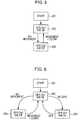
- Fig. 5 shows an example of the state transition flow in the position information detection unit 216 shown in Fig. 3 or 4 .
- “GPS On1” indicates a state of setting a short monitor cycle in the first position information obtaining unit 301
- GPS On2 indicates a state of setting a long monitor cycle in the first position information obtaining unit 301
- “GPS Off” indicates that an obtaining process of position information by the first position information obtaining unit 301 is in an OFF state
- “NW On” indicates that an obtaining process of position information by the second position information obtaining unit 302 is in an ON state
- “NW Off” indicates that an obtaining process of position information by the second position information obtaining unit 302 is in an OFF state (this is also true of the following).
- a position detection process by the position information detection unit 216 starts (501)
- the flow is transitioned to an obtaining process (502) of position information by the first position information obtaining unit 301.
- a short monitor cycle is set in the first position information obtaining unit 301 (GPS On1), and an operation of the second position information obtaining unit 302 stops (NW Off).
- this state (502) is maintained.
- the monitor cycle control unit 303 sets a long monitor cycle in the first position information obtaining unit 301 (GPS On2), and the flow is transitioned to a reduction process (503) of an obtaining frequency of position information. Since the first position information obtaining unit 301 is hardly moved, low power consumption is achieved by reducing a frequency of obtaining a position using a GPS signal. In this process (503) as well, the second position information obtaining unit 302 stops being operated (NW Off).
- the movement detection unit 304 detects that the first position information obtaining unit 301 is moved again after detecting that the first position information obtaining unit 301 is not moved
- the counting unit 305 counts a time period where the movement detection unit 304 detects the movement of the first position information obtaining unit 301.
- the time period reaches a predetermined value (count 1)
- the flow returns to the process (502), where the monitor cycle control unit 303 returns the monitor cycle to a short monitor cycle (GPS On1) such that the first position information obtaining unit 301 increases an obtaining frequency of position information again.
- Fig. 6 shows another example of the state transition flow in the position information detection unit 216 shown in Fig. 3 or 4 .
- a position detection process by the position information detection unit 216 starts (501)
- the flow is transitioned to an obtaining process (502) of position information by the first position information obtaining unit 301.
- a short monitor cycle is set in the first position information obtaining unit 301 (GPS On1), and an operation of the second position information obtaining unit 302 stops (NW Off).
- this state (502) is maintained.
- the monitor cycle control unit 303 sets a long monitor cycle in the first position information obtaining unit 301 (GPS On2), and the flow is transitioned to a reduction process (503) of an obtaining frequency of position information.
- the first position information obtaining unit 301 can receive a GPS signal, since the first position information obtaining unit 301 is hardly moved, low power consumption is achieved by reducing a frequency of obtaining a position using the GPS signal. In this process (503) as well, the second position information obtaining unit 302 stops being operated (NW Off).
- the movement detection unit 304 detects that the first position information obtaining unit 301 is moved again after detecting that the first position information obtaining unit 301 is not moved
- the counting unit 305 counts a time period where the movement detection unit 304 detects the movement of the first position information obtaining unit 301.
- the time period reaches a predetermined value (count 1)
- the flow returns to the process (502), where the monitor cycle control unit 303 returns the monitor cycle to a short monitor cycle (GPS On1) such that the first position information obtaining unit 301 increases an obtaining frequency of position information again.
- the position information obtainment determining unit 306 determines that the first position information obtaining unit 301 is not able to obtain position information
- the flow is transitioned to a process (504) where the second position information obtaining unit 302 starts an operation of an obtaining process of position information (NW On) in addition to the obtaining process (GPS On1) of position information by the first position information obtaining unit 301, and the obtaining processes of position information by the first position information obtaining unit 301 and the second position information obtaining unit 302 are performed in parallel.
- the position information obtainment determining unit 306 determines that the first position information obtaining unit 301 obtains position information, the operation of the obtaining process of position information by the second position information obtaining unit 302 stops (NW Off), and the flow returns to the process (502).
- Fig. 7 shows still another example of the state transition flow in the position information detection unit 216 shown in Fig. 3 or 4 .
- a position detection process by the position information detection unit 216 starts (501), for example, the flow is transitioned to an obtaining process (502) of position information by the first position information obtaining unit 301.
- a short monitor cycle is set in the first position information obtaining unit 301 (GPS On1), and an operation of the second position information obtaining unit 302 stops (NW Off).
- this state (502) is maintained.
- the monitor cycle control unit 303 sets a long monitor cycle in the first position information obtaining unit 301 (GPS On2), and the flow is transitioned to a reduction process (503) of an obtaining frequency of position information.
- the first position information obtaining unit 301 can receive a GPS signal, since the first position information obtaining unit 301 is hardly moved, low power consumption is achieved by reducing a frequency of obtaining a position using the GPS signal. In this process (503) as well, the second position information obtaining unit 302 stops being operated (NW Off).
- the movement detection unit 304 detects that the first position information obtaining unit 301 is moved again after detecting that the first position information obtaining unit 301 is not moved
- the counting unit 305 counts a time period where the movement detection unit 304 detects the movement of the first position information obtaining unit 301.
- the time period reaches a predetermined value (count 1)
- the flow returns to the process (502), where the monitor cycle control unit 303 returns a monitor cycle to a short monitor cycle (GPS On1) such that the first position information obtaining unit 301 increases an obtaining frequency of position information again.
- the position information obtainment determining unit 306 determines that the first position information obtaining unit 301 is not able to obtain position information
- the flow is transitioned to a process (506) where the monitor cycle control unit 303 sets a long monitor cycle (GPS On2) in the first position information obtaining unit 301, the second position information obtaining unit 302 starts an operation of an obtaining process of position information (NW On), and the obtaining processes of position information by the first position information obtaining unit 301 and the second position information obtaining unit 302 are performed in parallel.
- GPS On2 long monitor cycle
- the position information obtainment determining unit 306 determines that the first position information obtaining unit 301 obtains position information, the operation of the obtaining process of position information by the second position information obtaining unit 302 stops (NW Off), and the flow returns to the process (503).
- Fig. 8 shows still another example of the state transition flow in the position information detection unit 216 shown in Fig. 3 or 4 .
- a position detection process by the position information detection unit 216 starts (501)
- the flow is transitioned to an obtaining process (502) of position information by the first position information obtaining unit 301.
- a short monitor cycle is set in the first position information obtaining unit 301 (GPS On1), and an operation of the second position information obtaining unit 302 stops (NW Off).
- this state (502) is maintained.
- the position information obtainment determining unit 306 determines that the first position information obtaining unit 301 is not able to obtain position information
- the flow is transitioned to a process (504) where the second position information obtaining unit 302 starts an operation of an obtaining process of position information (NW On) in addition to the obtaining process (GPS On1) of position information by the first position information obtaining unit 301, and the obtaining processes of position information by the first position information obtaining unit 301 and the second position information obtaining unit 302 are performed in parallel.
- the position information obtainment determining unit 306 determines that the first position information obtaining unit 301 obtains position information, the operation of the obtaining process of position information by the second position information obtaining unit 302 stops (NW Off), and the flow returns to the process (502).
- the movement detection unit 304 further detects that the first position information obtaining unit 301 is not moved, the flow is transitioned to a process (505) where the first position information obtaining unit 301 enters an OFF state (GPS Off), and only the second position information obtaining unit 302 performs an obtaining process of position information.
- the first position information obtaining unit 301 may be varied to a state of being capable of receiving a GPS signal in a state of being incapable of receiving the GPS signal and of also not being moved. Therefore, low power consumption is achieved by stopping obtaining a position using the GPS signal.
- the movement detection unit 304 detects a movement of the first position information obtaining unit 301
- the flow returns to the process (504) where the first position information obtaining unit 301 enters on an ON state (GPS On1), and the obtaining processes of position information by the first position information obtaining unit 301 and the second position information obtaining unit 302 are performed in parallel.
- Fig. 9 shows still another example of the state transition flow in the position information detection unit 216 shown in Fig. 3 or 4 .
- the flow enters a state (504) where the second position information obtaining unit 302 starts an operation of an obtaining process of position information (NW On) in addition to the obtaining process (GPS On1) of position information by the first position information obtaining unit 301, and the obtaining processes of position information by the first position information obtaining unit 301 and the second position information obtaining unit 302 are performed in parallel.
- the movement detection unit 304 detects that the first position information obtaining unit 301 is not moved, there is little possibility that the first position information obtaining unit 301 may be varied to a state of being capable of receiving a GPS signal. Therefore, the flow is transitioned to a process (505) where the first position information obtaining unit 301 enters an OFF state (GPS Off), and only the second position information obtaining unit 302 performs an obtaining process of position information.
- the movement detection unit 304 detects a movement of the first position information obtaining unit 301
- the position information obtainment determining unit 306 determines that the first position information obtaining unit 301 is not able to obtain position information
- the counting unit 305 counts a time period where the first position information obtaining unit 301 is not able to obtain position information, and the time period exceeds a predetermined value (count 2)
- the flow is transitioned to a process (506) where the monitor cycle control unit 303 sets a long monitor cycle (GPS On2) in the first position information obtaining unit 301, and the obtaining processes of position information by the first position information obtaining unit 301 and the second position information obtaining unit 302 are performed in parallel. Since it is not able to be expected that a GPS signal can be received even if the first position information obtaining unit 301 is moved, low power consumption is achieved by reducing a frequency of obtaining a position using the GPS signal.
- the flow is transitioned to a process (505) where the first position information obtaining unit 301 enters an OFF state, and only the second position information obtaining unit 302 performs an obtaining process of position information. Since there is little possibility that the first position information obtaining unit 301 may be varied to a state of being capable of receiving a GPS signal in a state of not being moved, low power consumption is achieved by stopping obtaining a position using the GPS signal.
- Fig. 10 shows still another example of the state transition flow in the position information detection unit 216 shown in Fig. 3 or 4 .
- a position detection process by the position information detection unit 216 starts (501)
- the flow is transitioned to an obtaining process (502) of position information by the first position information obtaining unit 301.
- a short monitor cycle is set in the first position information obtaining unit 301 (GPS On1), and an operation of the second position information obtaining unit 302 stops (NW Off).
- this state (502) is maintained.
- the monitor cycle control unit 303 sets a long monitor cycle in the first position information obtaining unit 301 (GPS On2), and the flow is transitioned to a reduction process (503) of an obtaining frequency of position information. In this process as well, the second position information obtaining unit 302 stops being operated (NW Off).
- the movement detection unit 304 detects that the first position information obtaining unit 301 is moved again after detecting that the first position information obtaining unit 301 is not moved
- the counting unit 305 counts a time period where the movement detection unit 304 detects the movement of the first position information obtaining unit 301.
- the time period reaches a predetermined value (count 1)
- the flow returns to the process (502), where the monitor cycle control unit 303 returns a monitor cycle to a short monitor cycle (GPS On1) such that the first position information obtaining unit 301 increases an obtaining frequency of position information again.
- the transitioned state where the first position information obtaining unit 301 changes an obtaining frequency of position information is made to have hysteresis by changing a monitor cycle of the first position information obtaining unit 301 after the counting unit 305 counts the specific time period (count 1), and thereby it is possible to prevent a transition between the process (502) and the process (503) from being generated at a very high frequency.
- the position information obtainment determining unit 306 determines that the first position information obtaining unit 301 is not able to obtain position information
- the flow is transitioned to a process (504) where the second position information obtaining unit 302 starts an operation of an obtaining process of position information (NW On) in addition to the obtaining process (GPS On1) of position information by the first position information obtaining unit 301, and the obtaining processes of position information by the first position information obtaining unit 301 and the second position information obtaining unit 302 are performed in parallel.
- the position information obtainment determining unit 306 determines that the first position information obtaining unit 301 obtains position information, the operation of the obtaining process of position information by the second position information obtaining unit 302 stops (NW Off), and the flow returns to the process (502).
- the movement detection unit 304 further detects that the first position information obtaining unit 301 is not moved, the flow is transitioned to a process (505) where the first position information obtaining unit 301 enters an OFF state (GPS Off), and only the second position information obtaining unit 302 performs an obtaining process of position information.
- the movement detection unit 304 detects a movement of the first position information obtaining unit 301
- the flow returns to the process (504) where the first position information obtaining unit 301 enters an ON state (GPS On1), and the obtaining processes of position information by the first position information obtaining unit 301 and the second position information obtaining unit 302 are performed in parallel.
- the movement detection unit 304 detects a movement of the first position information obtaining unit 301
- the position information obtainment determining unit 306 determines that the first position information obtaining unit 301 is not able to obtain position information
- the counting unit 305 counts a time period where the first position information obtaining unit 301 is not able to obtain position information, and the time period exceeds a predetermined value (count 2)
- the flow is transitioned to a process (506) where the monitor cycle control unit 303 sets a long monitor cycle (GPS On2) in the first position information obtaining unit 301, and the obtaining processes of position information by the first position information obtaining unit 301 and the second position information obtaining unit 302 are performed in parallel.
- GPS On2 long monitor cycle
- the transitioned state where the first position information obtaining unit 301 changes an obtaining frequency of position information is made to have hysteresis by changing a monitor cycle of the first position information obtaining unit 301 after the counting unit 305 counts the specific time period (count 2), and thereby it is possible to prevent the transition between the process (504) and the process (505) from being generated at a very high frequency.
- the flow is transitioned to a process (505) where the first position information obtaining unit 301 enters an OFF state, and only the second position information obtaining unit 302 performs an obtaining process of position information.
- the position information obtainment determining unit 306 determines that the first position information obtaining unit 301 obtains position information
- the flow is transitioned to the above-described process (503) where the second position information obtaining unit 302 stops the operation of the obtaining process of position information (NW Off).
- the flow returns to a process (506) where the monitor cycle control unit 303 sets a long monitor cycle (GPS On2) in the first position information obtaining unit 301, and the obtaining processes of position information by the first position information obtaining unit 301 and the second position information obtaining unit 302 are performed in parallel.
- GPS On2 long monitor cycle
- an initial value (GPS On1) of the monitor cycle when the first position information obtaining unit 301 starts an obtaining process of position information is not unique.
- the monitor cycle control unit 303 may have a structure where the initial value (GPS On1) is changed depending on an application program during activation on the portable terminal 120.
- Fig. 13 shows a structure where the initial value (GPS On1) of the monitor cycle is switched depending on an application program during activation on the portable terminal 120, included in the monitor cycle control unit 303.
- the monitor cycle control unit 303 sets an initial value (GPS On1_1) of the shortest monitor cycle when this kind of application program is activated.
- the monitor cycle control unit 303 sets an initial value (GPS On1_2) of a relatively short monitor cycle.
- the monitor cycle control unit 303 may set an initial value (GPS On1_N) of a relatively long monitor cycle, thereby preferentially reducing power consumption.
- Fig. 11 shows an example of the functional configuration of the portable terminal 120 including the position information detection unit.
- the portable terminal 120 includes a position information detection unit 1101, a wireless parameter detection unit 1102, an obtained data synthesis unit 1103, and a communication unit 1104, as functional modules.
- the position information detection unit 1101 has the configuration shown in Fig. 3 or 4 . That is to say, the position information detection unit 1101 performs hybrid positioning using the first position information obtaining unit 301 and the second position information obtaining unit 302, and, as described above, operates the first position information obtaining unit 301 and the second position information obtaining unit 302 in a complementary manner based on a reception state of a GPS signal and a movement state of the first position information obtaining unit 301, thereby achieving low power consumption and obtaining higher accuracy position information.
- the wireless parameter detection unit 1102 and the communication unit 1104 correspond to the communication unit 215 shown in Fig. 2 .
- the communication unit 1104 is wirelessly connected to peripheral base stations and communicates other portable terminals.
- the wireless parameter detection unit 1102 detects wireless parameters when the communication unit 1104 receives signals from a plurality of peripheral public wireless base stations.
- the communication unit 1104 corresponds to a wireless multiple access method such as orthogonal frequency division multiple access (OFDMA), time division multiple access (TDMA) or code division multiple access (CDMA) (described above). Therefore, the wireless parameters detected by the wireless parameter detection unit 1102 may include the following.
- OFDMA orthogonal frequency division multiple access
- TDMA time division multiple access
- CDMA code division multiple access
- a ratio of the number of sub-carriers allocated by each user with respect to a total number of sub-carriers for each frame can be obtained by receiving, demodulating, and decoding a control signal included in a signal received from a public wireless station.
- a method for obtaining wireless parameters is disclosed in Japanese Patent Application No. 2010-142384 which has already been assigned to the present applicant.
- the obtained data synthesis unit 1103 correlates the wireless parameters detected by the wireless parameter detection unit 1102 with position information and time information detected by the position information detection unit 1101 at the time of the detection thereof.
- the communication unit 1104 may transmit data created by the obtained data synthesis unit 1103 to an arbitrary server at an arbitrary timing.
- the server side can grasp a traffic situation at each point by collecting the wireless parameters correlated with the position information and the time information from a plurality of portable terminals, and perform a service such as sending a notification of the traffic situation to each portable terminal.
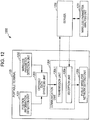
- Fig. 12 schematically shows a configuration example of the communication system 1200 including a portable terminal which obtains position information and detects wireless parameters and a server which collects the wireless parameters from the portable terminal.
- the portable terminal 120 includes a position information detection unit 1201, a wireless parameter detection unit 1202, an obtained data synthesis unit 1203, a communication unit 1204, and a public wireless network setting unit 1205 as functional modules.
- the position information detection unit 1201 includes the configuration shown in Fig. 3 or 4 and performs hybrid positioning.
- the wireless parameter detection unit 1202 and the communication unit 1204 correspond to the communication unit 215 shown in Fig. 2 .
- the communication unit 1204 is wirelessly connected to peripheral base stations and communicates other portable terminals.
- the wireless parameter detection unit 1202 detects wireless parameters when the communication unit 1204 receives signals from a plurality of peripheral public wireless base stations (described above).
- the obtained data synthesis unit 1203 correlates the wireless parameters detected by the wireless parameter detection unit 1202 with position information and time information detected by the position information detection unit 1201 at the time of the detection thereof.
- the communication unit 1204 includes a transmission unit 1204-1 and a reception unit 1204-2.
- the transmission unit 1204-1 may transmit data created by the obtained data synthesis unit 1203 to a server 1230 at an arbitrary timing.
- the server 1230 includes a wireless parameter analysis unit 1231, collects wireless parameters correlated with position information and time information from a plurality of portable terminals, analyzes the wireless parameters using the wireless parameter analysis unit 1231, and evaluates one or a plurality of public wireless base stations which are located around the portable terminal which is a transmission source of each wireless parameter.
- the wireless parameter analysis unit 1231 may rank a plurality of public wireless base stations (telecommunications carriers) present around a position of each portable terminal, a carrier frequency, a frequency bandwidth, and a wireless method based on the state of congestion or the expected value of a communication rate, through the analysis of the wireless parameters.
- the wireless parameter analysis unit 1231 may use communication expenses for each base station (telecommunications carrier) as an index at the time of the ranking.
- the server 1230 feeds back the estimated result to each portable terminal.
- the portable terminal 120 If the reception unit 1214-2 receives the estimated result from the server 1230, the portable terminal 120 enables the public wireless network setting unit 1215 to select a public wireless network to be used, and set a carrier frequency, a frequency bandwidth, a wireless method, and the like, based on the evaluation result.
Landscapes
- Engineering & Computer Science (AREA)
- Radar, Positioning & Navigation (AREA)
- Remote Sensing (AREA)
- Physics & Mathematics (AREA)
- General Physics & Mathematics (AREA)
- Computer Networks & Wireless Communication (AREA)
- Position Fixing By Use Of Radio Waves (AREA)
- Mobile Radio Communication Systems (AREA)
- Telephone Function (AREA)
Claims (5)
- Positionsdetektionsvorrichtung, die Folgendes umfasst:eine erste Positionserhalteeinheit (301), die Positionsinformationen durch Empfangen eines GPS(Globales-Positionierungssystem)-Signals erhält;eine zweite Positionserhalteeinheit (302), die Positionsinformationen basierend auf von mehreren peripheren Basisstationen erhaltenen Informationen erhält;eine Positionsinformationserlangung-Bestimmungseinheit (306), die bestimmt, ob die erste Positionserhalteeinheit Positionsinformationen erhält oder nicht;eine Bewegungsdetektionseinheit (304), die detektiert, ob die erste Positionserhalteeinheit (301) bewegt wird oder nicht;eine erste Zustandssteuereinheit (307), die die erste Positionserhalteeinheit (301) ausschaltet, falls die Bewegungsdetektionseinheit (304) detektiert, dass die erste Positionserhalteeinheit (301) nicht bewegt wird, und die Positionsinformationserlangung-Bestimmungseinheit (306) bestimmt, dass die erste Positionserhalteeinheit (301) nicht in der Lage ist, Positionsinformationen zu erhalten, und die die erste Positionserhalteeinheit (301) einschaltet, falls die Bewegungsdetektionseinheit (304) detektiert, dass die erste Positionserhalteeinheit (301) bewegt wird, wenn die erste Positionserhalteeinheit ausgeschaltet ist;eine zweite Zustandssteuereinheit (308), die die zweite Positionserhalteeinheit (302) ausschaltet, wenn die Positionsinformationserlangung-Bestimmungseinheit (306) bestimmt, dass die erste Positionserhalteeinheit (301) Positionsinformationen erhält, wenn die zweite Positionserhalteeinheit (302) eingeschaltet ist, und die die zweite Positionserhalteeinheit (302) einschaltet, wenn die Positionsinformationserlangung-Bestimmungseinheit (306) bestimmt, dass die erste Positionserhalteeinheit (301) keine Positionsinformationen erhält;eine Überwachungszyklussteuereinheit (303), die einen Überwachungszyklus derart steuert, dass die erste Positionserhalteeinheit Positionsinformationen häufiger erhält, wenn die Bewegungsdetektionseinheit angibt, dass sich die erste Positionserhalteeinheit (301) bewegt, als wenn sie sich nicht bewegt; undeine Ausgabeeinheit (309), die eines von zwei Positionsinformationselementen, die durch die erste Positionserhalteeinheit und die zweite Positionserhalteeinheit erhalten werden, auswählt und ausgibt.
- Positionsdetektionsvorrichtung nach Anspruch 1, wobei die Überwachungszyklussteuereinheit den Überwachungszyklus verkürzt, falls die Bewegungsdetektionseinheit detektiert, dass die erste Positionserhalteeinheit bewegt wird, und den Überwachungszyklus verlängert, falls die Bewegungsdetektionseinheit detektiert, dass die erste Positionserhalteeinheit nicht bewegt wird.
- Positionsdetektionsvorrichtung nach Anspruch 2, die ferner eine Zähleinheit umfasst, die eine Zeitspanne zählt, in der die Bewegungsdetektionseinheit eine Bewegung der ersten Positionserhalteeinheit detektiert, falls die Bewegungsdetektionseinheit die Bewegung der ersten Positionserhalteeinheit erneut detektiert, nachdem die erste Positionserhalteeinheit als nicht bewegt detektiert wird,
wobei die Überwachungszyklussteuereinheit den Überwachungszyklus zu einem kurzen Überwachungszyklus zurücksetzt, nachdem die Zähleinheit eine erste vorbestimmte Zeitspanne zählt. - Positionsdetektionsvorrichtung nach Anspruch 1, wobei die Bewegungsdetektionseinheit Folgendes beinhaltet: eine Beschleunigungsdetektionseinheit, die eine durch eine Bewegung der ersten Positionserhalteeinheit verursachte Beschleunigung detektiert, und eine Distanzberechnungseinheit, die eine Bewegungsdistanz der ersten Positionserhalteeinheit für eine vorbestimmte Zeit basierend auf der durch die Beschleunigungsdetektionseinheit detektierten Beschleunigung berechnet, und
wobei die Überwachungszyklussteuereinheit den Überwachungszyklus basierend auf der durch die Distanzberechnungseinheit berechneten Bewegungsdistanz steuert. - Positionsdetektionsvorrichtung nach Anspruch 4, wobei die Überwachungszyklussteuereinheit einen oder mehrere Schwellenwerte aufweist und eine derartige Steuerung durchführt, dass der Überwachungszyklus verkürzt wird, falls die Bewegungsdistanz jeden Schwellenwert überschreitet, und der Überwachungszyklus verlängert wird, falls die Bewegungsdistanz geringer als jeder Schwellenwert ist.
Applications Claiming Priority (1)
| Application Number | Priority Date | Filing Date | Title |
|---|---|---|---|
| JP2010252412A JP2012103138A (ja) | 2010-11-11 | 2010-11-11 | 位置情報検出装置、通信装置、並びに通信システム |
Publications (3)
| Publication Number | Publication Date |
|---|---|
| EP2453262A2 EP2453262A2 (de) | 2012-05-16 |
| EP2453262A3 EP2453262A3 (de) | 2013-10-23 |
| EP2453262B1 true EP2453262B1 (de) | 2020-05-06 |
Family
ID=45002626
Family Applications (1)
| Application Number | Title | Priority Date | Filing Date |
|---|---|---|---|
| EP11187072.1A Active EP2453262B1 (de) | 2010-11-11 | 2011-10-28 | Positionsinformationserkennungsvorrichtung |
Country Status (3)
| Country | Link |
|---|---|
| US (1) | US8823584B2 (de) |
| EP (1) | EP2453262B1 (de) |
| JP (1) | JP2012103138A (de) |
Families Citing this family (24)
| Publication number | Priority date | Publication date | Assignee | Title |
|---|---|---|---|---|
| KR102058947B1 (ko) * | 2012-05-24 | 2019-12-24 | 엘지전자 주식회사 | 이동 단말기 및 그의 gps엔진 제어방법 |
| US9088865B2 (en) * | 2012-06-06 | 2015-07-21 | Facebook, Inc. | Global-positioning system (GPS) update interval based on sensor |
| AU2013271709A1 (en) * | 2012-06-06 | 2015-01-22 | Facebook, Inc. | Method, one or more computer-readable non-transitory storage media and a device generally relating to location tracking |
| US9008694B2 (en) * | 2012-06-29 | 2015-04-14 | Broadcom Corporation | Indoor/outdoor differentiation using radio frequency (RF) transmitters |
| US9116233B2 (en) * | 2012-07-10 | 2015-08-25 | Broadcom Corporation | Power mode control for sensors |
| WO2014083734A1 (ja) | 2012-11-29 | 2014-06-05 | 日本電気株式会社 | 位置情報管理システム、移動局、サービス管理サーバ、移動検知方法及び非一時的なコンピュータ可読媒体 |
| US9794736B2 (en) * | 2012-12-21 | 2017-10-17 | Qualcomm Incorporated | Low power always-on determination of indoor versus outdoor state |
| JP2016513395A (ja) * | 2013-02-06 | 2016-05-12 | フェイスブック,インク. | センサに基づく全地球測位システム(gps)更新間隔 |
| US9606241B2 (en) * | 2013-02-21 | 2017-03-28 | Apple Inc. | Sensor-assisted location fix |
| US9247518B2 (en) * | 2013-03-12 | 2016-01-26 | Qualcomm Incorporated | Mobile device positioning responsive to externally generated regional candidate position fix mode selection |
| US9377519B2 (en) * | 2013-03-12 | 2016-06-28 | Qualcomm Incorporated | Server-based mobile device regional candidate position fix mode selection |
| JP2014185859A (ja) * | 2013-03-21 | 2014-10-02 | Fujitsu Ltd | 携帯情報端末の制御方法、制御プログラム、携帯情報端末 |
| JP5571858B1 (ja) | 2014-01-23 | 2014-08-13 | ナレッジスイート株式会社 | 活動管理用無線通信端末及びプログラム |
| JP6260703B2 (ja) * | 2014-07-08 | 2018-01-17 | 日本電気株式会社 | 情報共有装置及び情報共有方法、情報共有システム、並びにコンピュータ・プログラム |
| EP3869234A1 (de) | 2015-06-02 | 2021-08-25 | Hangit Llc | Lokalisierung einer mobilen vorrichtung |
| JP2019508965A (ja) * | 2016-02-03 | 2019-03-28 | トゥーセンス、インク.Twosense, Inc. | インテリジェントなジオロケーションの選択を使用してモバイルデバイスの電力を最大化するためのシステムおよび方法 |
| CN106792882B (zh) * | 2016-12-30 | 2020-03-27 | 华为技术有限公司 | 网络评估方法及装置 |
| JP6429936B2 (ja) * | 2017-05-09 | 2018-11-28 | Kddi株式会社 | 位置情報管理装置、位置情報管理方法、及びプログラム |
| JP2020134486A (ja) * | 2019-02-26 | 2020-08-31 | 日本電気通信システム株式会社 | 位置測位装置、位置測位方法及びコンピュータプログラム |
| WO2020175778A1 (en) * | 2019-02-28 | 2020-09-03 | Samsung Electronics Co., Ltd. | Electronic device for supporting user state-based geofencing services |
| KR102785619B1 (ko) * | 2019-03-19 | 2025-03-26 | 삼성전자 주식회사 | 무선 통신 채널을 통한 주기적인 측위 통신을 제공하는 전자 장치 |
| JP6947199B2 (ja) * | 2019-03-25 | 2021-10-13 | カシオ計算機株式会社 | 電子機器、制御方法及びプログラム |
| CN112135247B (zh) * | 2020-09-27 | 2023-03-31 | 浙江大华技术股份有限公司 | 一种数据传输方法、装置、存储介质及电子装置 |
| JP7352715B1 (ja) | 2022-12-07 | 2023-09-28 | Kddi株式会社 | 情報処理装置及び情報処理方法 |
Family Cites Families (32)
| Publication number | Priority date | Publication date | Assignee | Title |
|---|---|---|---|---|
| JPH09311043A (ja) * | 1996-05-24 | 1997-12-02 | Matsushita Electric Ind Co Ltd | ナビゲーション装置 |
| JP3398585B2 (ja) * | 1997-10-28 | 2003-04-21 | セイコーインスツルメンツ株式会社 | 携帯型速度・距離計 |
| JP2000098017A (ja) * | 1998-09-22 | 2000-04-07 | Matsushita Electric Works Ltd | 位置検出用端末機 |
| JP4239317B2 (ja) * | 1999-04-07 | 2009-03-18 | カシオ計算機株式会社 | 測位装置および測位制御方法 |
| GB2400525B (en) * | 2000-04-20 | 2004-11-24 | Nec Corp | Mobile telephone system and apparatus capable of effectively utilizing GPS information even if direct reception by a mobile telephone apparatus is difficult |
| JP2001305206A (ja) * | 2000-04-25 | 2001-10-31 | Matsushita Electric Works Ltd | Gps受信装置 |
| JP2002296340A (ja) * | 2001-03-30 | 2002-10-09 | Koden Electronics Co Ltd | 測位用衛星信号受信機 |
| JP2002320254A (ja) * | 2001-04-20 | 2002-10-31 | Pioneer Electronic Corp | 移動体通信装置及びその位置検出方法 |
| US6584331B2 (en) * | 2001-10-09 | 2003-06-24 | Nokia Corporation | Use of received signal strength indicator (RSSI) and global positioning system (GPS) to reduce power consumption in mobile station |
| JP2003284123A (ja) * | 2002-03-22 | 2003-10-03 | Matsushita Electric Works Ltd | 位置情報端末 |
| JP2004048473A (ja) * | 2002-07-12 | 2004-02-12 | Hitachi Building Systems Co Ltd | 移動体位置通報装置 |
| JP4474831B2 (ja) * | 2003-01-28 | 2010-06-09 | 日本電気株式会社 | 移動通信網における移動局位置特定システム、制御装置及び移動局 |
| US7409188B2 (en) * | 2003-11-26 | 2008-08-05 | Nokia Corporation | Method and apparatus for lowering power use by a ranging receiver |
| GB2409376B (en) * | 2003-12-17 | 2006-06-28 | Motorola Inc | A subscriber unit, a cellular communication system and a method for determining a location therefor |
| JP4275006B2 (ja) * | 2004-05-26 | 2009-06-10 | 富士通株式会社 | 位置情報測定システム、端末及び位置情報測定プログラム |
| US7408506B2 (en) * | 2004-11-19 | 2008-08-05 | Intel Corporation | Method and apparatus for conserving power on a mobile device through motion awareness |
| US7701388B2 (en) | 2005-11-15 | 2010-04-20 | O2Micro International Ltd. | Novas hybrid positioning technology using terrestrial digital broadcasting signal (DBS) and global positioning system (GPS) satellite signal |
| US7633389B2 (en) * | 2006-04-14 | 2009-12-15 | Motorola, Inc. | Location enabled device with power saving control and method thereof |
| JP2008051808A (ja) * | 2006-07-28 | 2008-03-06 | Ntt Docomo Inc | 移動通信端末、gps測位方法、測位演算システム及び測位サーバ |
| JP2008136429A (ja) * | 2006-12-04 | 2008-06-19 | Shigeru Toyoda | うどん、麺類の茹で時間の短縮方法。 |
| US7847726B2 (en) * | 2006-12-22 | 2010-12-07 | Sirf Technology Holdings, Inc. | Navigational signal tracking in low power mode |
| JP2008298484A (ja) * | 2007-05-29 | 2008-12-11 | Kyocera Corp | 無線通信システム、移動端末、基地局、および移動端末の位置取得方法 |
| JP2009048088A (ja) * | 2007-08-22 | 2009-03-05 | Fuji Xerox Co Ltd | 画像形成装置 |
| JP2009063451A (ja) * | 2007-09-06 | 2009-03-26 | Sony Corp | 測位装置及び測位方法 |
| CN101822089B (zh) * | 2007-10-11 | 2013-07-24 | 日本电气株式会社 | 无线通信系统和方法 |
| US8467804B2 (en) * | 2007-10-16 | 2013-06-18 | Sony Corporation | Mobile terminals and methods for regulating power-on/off of a GPS positioning circuit |
| US8214139B2 (en) * | 2008-01-25 | 2012-07-03 | Garmin Switzerland Gmbh | Position source selection |
| US8072379B2 (en) * | 2008-05-12 | 2011-12-06 | Qualcomm Incorporated | GPS power savings using low power sensors |
| JP5168728B2 (ja) * | 2008-08-05 | 2013-03-27 | カシオ計算機株式会社 | 位置検出装置および位置検出プログラム |
| JP5257048B2 (ja) | 2008-12-18 | 2013-08-07 | 株式会社三洋物産 | 遊技機 |
| JP5349121B2 (ja) | 2009-04-10 | 2013-11-20 | 三菱電機株式会社 | 車両用同期機制御装置 |
| US8193982B2 (en) * | 2009-06-29 | 2012-06-05 | Research In Motion Limited | Controlling a GPS receiver by detecting motion based on radiofrequency signal traces |
-
2010
- 2010-11-11 JP JP2010252412A patent/JP2012103138A/ja active Pending
-
2011
- 2011-10-28 EP EP11187072.1A patent/EP2453262B1/de active Active
- 2011-11-02 US US13/287,766 patent/US8823584B2/en active Active
Non-Patent Citations (1)
| Title |
|---|
| None * |
Also Published As
| Publication number | Publication date |
|---|---|
| CN102572684A (zh) | 2012-07-11 |
| EP2453262A3 (de) | 2013-10-23 |
| EP2453262A2 (de) | 2012-05-16 |
| JP2012103138A (ja) | 2012-05-31 |
| US8823584B2 (en) | 2014-09-02 |
| US20120119948A1 (en) | 2012-05-17 |
Similar Documents
| Publication | Publication Date | Title |
|---|---|---|
| EP2453262B1 (de) | Positionsinformationserkennungsvorrichtung | |
| US12250051B2 (en) | Electronic device and method for measuring a beam quality of a currently serving beam based on a prediction window when the detected beam quality is within a particular range | |
| JP7306393B2 (ja) | 無線通信システムにおける装置及び方法 | |
| RU2713482C1 (ru) | Способ прерывистого приема и устройство | |
| CN115942502A (zh) | 随机接入资源选择、配置方法、装置、终端及网络侧设备 | |
| KR102508265B1 (ko) | 전자 디바이스 및 무선 통신 방법 | |
| KR20130092486A (ko) | 제한된 서비스에서 최적화된 높은 우선순위 plmn 검색 및 일반 서비스 스캔을 위한 방법 | |
| CN107371119A (zh) | 电子装置、信息处理设备和信息处理方法 | |
| EP4329412A1 (de) | Planung einer elektronischen vorrichtung und mitgliederelektronikvorrichtung für drahtlose kommunikation und verfahren | |
| KR102480279B1 (ko) | 무선 통신 시스템 내의 디바이스, 및 무선 통신 방법 | |
| US9380519B2 (en) | Using motion to improve local wireless network connectivity | |
| WO2019059134A1 (ja) | 通信品質調整システム | |
| US20180227803A1 (en) | Quality of service control | |
| JP2012075043A (ja) | 無線通信方法及び無線装置 | |
| JP2013125997A (ja) | 表示制御装置、表示制御方法およびプログラム | |
| Dräxler et al. | Anticipatory buffer control and quality selection for wireless video streaming | |
| CN102572684B (zh) | 位置信息检测装置、通信设备以及通信系统 | |
| EP3927051B1 (de) | Kommunikationsvorrichtung, kommunikationsverfahren und aufzeichnungsmedium | |
| KR20230088403A (ko) | 무선 통신을 위한 송신 전자 디바이스 및 수신 전자 디바이스 및 방법들 | |
| CN117580131A (zh) | 一种切片信息的指示方法、终端设备及网络设备 | |
| WO2025036591A1 (en) | Extension of an active time of a user equipment | |
| WO2025131427A1 (en) | Apparatus, method and computer program | |
| WO2025131429A1 (en) | Apparatus, method and computer program | |
| WO2025062275A1 (en) | Apparatus, method and computer program | |
| WO2024162884A1 (en) | Methods to operate wur without sleeping |
Legal Events
| Date | Code | Title | Description |
|---|---|---|---|
| PUAI | Public reference made under article 153(3) epc to a published international application that has entered the european phase |
Free format text: ORIGINAL CODE: 0009012 |
|
| 17P | Request for examination filed |
Effective date: 20111117 |
|
| AK | Designated contracting states |
Kind code of ref document: A2 Designated state(s): AL AT BE BG CH CY CZ DE DK EE ES FI FR GB GR HR HU IE IS IT LI LT LU LV MC MK MT NL NO PL PT RO RS SE SI SK SM TR |
|
| AX | Request for extension of the european patent |
Extension state: BA ME |
|
| RIC1 | Information provided on ipc code assigned before grant |
Ipc: G01S 19/34 20100101ALI20130619BHEP Ipc: G01S 19/48 20100101AFI20130619BHEP |
|
| PUAL | Search report despatched |
Free format text: ORIGINAL CODE: 0009013 |
|
| AK | Designated contracting states |
Kind code of ref document: A3 Designated state(s): AL AT BE BG CH CY CZ DE DK EE ES FI FR GB GR HR HU IE IS IT LI LT LU LV MC MK MT NL NO PL PT RO RS SE SI SK SM TR |
|
| AX | Request for extension of the european patent |
Extension state: BA ME |
|
| RIC1 | Information provided on ipc code assigned before grant |
Ipc: G01S 19/48 20100101ALI20130919BHEP Ipc: G01S 19/34 20100101AFI20130919BHEP |
|
| STAA | Information on the status of an ep patent application or granted ep patent |
Free format text: STATUS: EXAMINATION IS IN PROGRESS |
|
| 17Q | First examination report despatched |
Effective date: 20161123 |
|
| GRAP | Despatch of communication of intention to grant a patent |
Free format text: ORIGINAL CODE: EPIDOSNIGR1 |
|
| STAA | Information on the status of an ep patent application or granted ep patent |
Free format text: STATUS: GRANT OF PATENT IS INTENDED |
|
| INTG | Intention to grant announced |
Effective date: 20191212 |
|
| GRAS | Grant fee paid |
Free format text: ORIGINAL CODE: EPIDOSNIGR3 |
|
| GRAA | (expected) grant |
Free format text: ORIGINAL CODE: 0009210 |
|
| STAA | Information on the status of an ep patent application or granted ep patent |
Free format text: STATUS: THE PATENT HAS BEEN GRANTED |
|
| AK | Designated contracting states |
Kind code of ref document: B1 Designated state(s): AL AT BE BG CH CY CZ DE DK EE ES FI FR GB GR HR HU IE IS IT LI LT LU LV MC MK MT NL NO PL PT RO RS SE SI SK SM TR |
|
| REG | Reference to a national code |
Ref country code: GB Ref legal event code: FG4D |
|
| REG | Reference to a national code |
Ref country code: CH Ref legal event code: EP Ref country code: AT Ref legal event code: REF Ref document number: 1267669 Country of ref document: AT Kind code of ref document: T Effective date: 20200515 |
|
| REG | Reference to a national code |
Ref country code: IE Ref legal event code: FG4D |
|
| REG | Reference to a national code |
Ref country code: DE Ref legal event code: R096 Ref document number: 602011066648 Country of ref document: DE |
|
| REG | Reference to a national code |
Ref country code: LT Ref legal event code: MG4D |
|
| REG | Reference to a national code |
Ref country code: NL Ref legal event code: MP Effective date: 20200506 |
|
| PG25 | Lapsed in a contracting state [announced via postgrant information from national office to epo] |
Ref country code: PT Free format text: LAPSE BECAUSE OF FAILURE TO SUBMIT A TRANSLATION OF THE DESCRIPTION OR TO PAY THE FEE WITHIN THE PRESCRIBED TIME-LIMIT Effective date: 20200907 Ref country code: GR Free format text: LAPSE BECAUSE OF FAILURE TO SUBMIT A TRANSLATION OF THE DESCRIPTION OR TO PAY THE FEE WITHIN THE PRESCRIBED TIME-LIMIT Effective date: 20200807 Ref country code: FI Free format text: LAPSE BECAUSE OF FAILURE TO SUBMIT A TRANSLATION OF THE DESCRIPTION OR TO PAY THE FEE WITHIN THE PRESCRIBED TIME-LIMIT Effective date: 20200506 Ref country code: NO Free format text: LAPSE BECAUSE OF FAILURE TO SUBMIT A TRANSLATION OF THE DESCRIPTION OR TO PAY THE FEE WITHIN THE PRESCRIBED TIME-LIMIT Effective date: 20200806 Ref country code: IS Free format text: LAPSE BECAUSE OF FAILURE TO SUBMIT A TRANSLATION OF THE DESCRIPTION OR TO PAY THE FEE WITHIN THE PRESCRIBED TIME-LIMIT Effective date: 20200906 Ref country code: SE Free format text: LAPSE BECAUSE OF FAILURE TO SUBMIT A TRANSLATION OF THE DESCRIPTION OR TO PAY THE FEE WITHIN THE PRESCRIBED TIME-LIMIT Effective date: 20200506 Ref country code: LT Free format text: LAPSE BECAUSE OF FAILURE TO SUBMIT A TRANSLATION OF THE DESCRIPTION OR TO PAY THE FEE WITHIN THE PRESCRIBED TIME-LIMIT Effective date: 20200506 |
|
| PG25 | Lapsed in a contracting state [announced via postgrant information from national office to epo] |
Ref country code: BG Free format text: LAPSE BECAUSE OF FAILURE TO SUBMIT A TRANSLATION OF THE DESCRIPTION OR TO PAY THE FEE WITHIN THE PRESCRIBED TIME-LIMIT Effective date: 20200806 Ref country code: HR Free format text: LAPSE BECAUSE OF FAILURE TO SUBMIT A TRANSLATION OF THE DESCRIPTION OR TO PAY THE FEE WITHIN THE PRESCRIBED TIME-LIMIT Effective date: 20200506 Ref country code: RS Free format text: LAPSE BECAUSE OF FAILURE TO SUBMIT A TRANSLATION OF THE DESCRIPTION OR TO PAY THE FEE WITHIN THE PRESCRIBED TIME-LIMIT Effective date: 20200506 Ref country code: LV Free format text: LAPSE BECAUSE OF FAILURE TO SUBMIT A TRANSLATION OF THE DESCRIPTION OR TO PAY THE FEE WITHIN THE PRESCRIBED TIME-LIMIT Effective date: 20200506 |
|
| REG | Reference to a national code |
Ref country code: AT Ref legal event code: MK05 Ref document number: 1267669 Country of ref document: AT Kind code of ref document: T Effective date: 20200506 |
|
| PG25 | Lapsed in a contracting state [announced via postgrant information from national office to epo] |
Ref country code: NL Free format text: LAPSE BECAUSE OF FAILURE TO SUBMIT A TRANSLATION OF THE DESCRIPTION OR TO PAY THE FEE WITHIN THE PRESCRIBED TIME-LIMIT Effective date: 20200506 Ref country code: AL Free format text: LAPSE BECAUSE OF FAILURE TO SUBMIT A TRANSLATION OF THE DESCRIPTION OR TO PAY THE FEE WITHIN THE PRESCRIBED TIME-LIMIT Effective date: 20200506 |
|
| PG25 | Lapsed in a contracting state [announced via postgrant information from national office to epo] |
Ref country code: DK Free format text: LAPSE BECAUSE OF FAILURE TO SUBMIT A TRANSLATION OF THE DESCRIPTION OR TO PAY THE FEE WITHIN THE PRESCRIBED TIME-LIMIT Effective date: 20200506 Ref country code: EE Free format text: LAPSE BECAUSE OF FAILURE TO SUBMIT A TRANSLATION OF THE DESCRIPTION OR TO PAY THE FEE WITHIN THE PRESCRIBED TIME-LIMIT Effective date: 20200506 Ref country code: AT Free format text: LAPSE BECAUSE OF FAILURE TO SUBMIT A TRANSLATION OF THE DESCRIPTION OR TO PAY THE FEE WITHIN THE PRESCRIBED TIME-LIMIT Effective date: 20200506 Ref country code: SM Free format text: LAPSE BECAUSE OF FAILURE TO SUBMIT A TRANSLATION OF THE DESCRIPTION OR TO PAY THE FEE WITHIN THE PRESCRIBED TIME-LIMIT Effective date: 20200506 Ref country code: RO Free format text: LAPSE BECAUSE OF FAILURE TO SUBMIT A TRANSLATION OF THE DESCRIPTION OR TO PAY THE FEE WITHIN THE PRESCRIBED TIME-LIMIT Effective date: 20200506 Ref country code: IT Free format text: LAPSE BECAUSE OF FAILURE TO SUBMIT A TRANSLATION OF THE DESCRIPTION OR TO PAY THE FEE WITHIN THE PRESCRIBED TIME-LIMIT Effective date: 20200506 Ref country code: ES Free format text: LAPSE BECAUSE OF FAILURE TO SUBMIT A TRANSLATION OF THE DESCRIPTION OR TO PAY THE FEE WITHIN THE PRESCRIBED TIME-LIMIT Effective date: 20200506 Ref country code: CZ Free format text: LAPSE BECAUSE OF FAILURE TO SUBMIT A TRANSLATION OF THE DESCRIPTION OR TO PAY THE FEE WITHIN THE PRESCRIBED TIME-LIMIT Effective date: 20200506 |
|
| REG | Reference to a national code |
Ref country code: DE Ref legal event code: R097 Ref document number: 602011066648 Country of ref document: DE |
|
| PG25 | Lapsed in a contracting state [announced via postgrant information from national office to epo] |
Ref country code: PL Free format text: LAPSE BECAUSE OF FAILURE TO SUBMIT A TRANSLATION OF THE DESCRIPTION OR TO PAY THE FEE WITHIN THE PRESCRIBED TIME-LIMIT Effective date: 20200506 Ref country code: SK Free format text: LAPSE BECAUSE OF FAILURE TO SUBMIT A TRANSLATION OF THE DESCRIPTION OR TO PAY THE FEE WITHIN THE PRESCRIBED TIME-LIMIT Effective date: 20200506 |
|
| PLBE | No opposition filed within time limit |
Free format text: ORIGINAL CODE: 0009261 |
|
| STAA | Information on the status of an ep patent application or granted ep patent |
Free format text: STATUS: NO OPPOSITION FILED WITHIN TIME LIMIT |
|
| 26N | No opposition filed |
Effective date: 20210209 |
|
| PG25 | Lapsed in a contracting state [announced via postgrant information from national office to epo] |
Ref country code: SI Free format text: LAPSE BECAUSE OF FAILURE TO SUBMIT A TRANSLATION OF THE DESCRIPTION OR TO PAY THE FEE WITHIN THE PRESCRIBED TIME-LIMIT Effective date: 20200506 |
|
| REG | Reference to a national code |
Ref country code: CH Ref legal event code: PL |
|
| GBPC | Gb: european patent ceased through non-payment of renewal fee |
Effective date: 20201028 |
|
| PG25 | Lapsed in a contracting state [announced via postgrant information from national office to epo] |
Ref country code: LU Free format text: LAPSE BECAUSE OF NON-PAYMENT OF DUE FEES Effective date: 20201028 Ref country code: MC Free format text: LAPSE BECAUSE OF FAILURE TO SUBMIT A TRANSLATION OF THE DESCRIPTION OR TO PAY THE FEE WITHIN THE PRESCRIBED TIME-LIMIT Effective date: 20200506 |
|
| REG | Reference to a national code |
Ref country code: BE Ref legal event code: MM Effective date: 20201031 |
|
| PG25 | Lapsed in a contracting state [announced via postgrant information from national office to epo] |
Ref country code: FR Free format text: LAPSE BECAUSE OF NON-PAYMENT OF DUE FEES Effective date: 20201031 |
|
| PG25 | Lapsed in a contracting state [announced via postgrant information from national office to epo] |
Ref country code: GB Free format text: LAPSE BECAUSE OF NON-PAYMENT OF DUE FEES Effective date: 20201028 Ref country code: LI Free format text: LAPSE BECAUSE OF NON-PAYMENT OF DUE FEES Effective date: 20201031 Ref country code: BE Free format text: LAPSE BECAUSE OF NON-PAYMENT OF DUE FEES Effective date: 20201031 Ref country code: CH Free format text: LAPSE BECAUSE OF NON-PAYMENT OF DUE FEES Effective date: 20201031 |
|
| PG25 | Lapsed in a contracting state [announced via postgrant information from national office to epo] |
Ref country code: IE Free format text: LAPSE BECAUSE OF NON-PAYMENT OF DUE FEES Effective date: 20201028 |
|
| PGFP | Annual fee paid to national office [announced via postgrant information from national office to epo] |
Ref country code: DE Payment date: 20210921 Year of fee payment: 11 |
|
| PG25 | Lapsed in a contracting state [announced via postgrant information from national office to epo] |
Ref country code: TR Free format text: LAPSE BECAUSE OF FAILURE TO SUBMIT A TRANSLATION OF THE DESCRIPTION OR TO PAY THE FEE WITHIN THE PRESCRIBED TIME-LIMIT Effective date: 20200506 Ref country code: MT Free format text: LAPSE BECAUSE OF FAILURE TO SUBMIT A TRANSLATION OF THE DESCRIPTION OR TO PAY THE FEE WITHIN THE PRESCRIBED TIME-LIMIT Effective date: 20200506 Ref country code: CY Free format text: LAPSE BECAUSE OF FAILURE TO SUBMIT A TRANSLATION OF THE DESCRIPTION OR TO PAY THE FEE WITHIN THE PRESCRIBED TIME-LIMIT Effective date: 20200506 |
|
| PG25 | Lapsed in a contracting state [announced via postgrant information from national office to epo] |
Ref country code: MK Free format text: LAPSE BECAUSE OF FAILURE TO SUBMIT A TRANSLATION OF THE DESCRIPTION OR TO PAY THE FEE WITHIN THE PRESCRIBED TIME-LIMIT Effective date: 20200506 |
|
| REG | Reference to a national code |
Ref country code: DE Ref legal event code: R119 Ref document number: 602011066648 Country of ref document: DE |
|
| PG25 | Lapsed in a contracting state [announced via postgrant information from national office to epo] |
Ref country code: DE Free format text: LAPSE BECAUSE OF NON-PAYMENT OF DUE FEES Effective date: 20230503 |