EP2452121B1 - Kombinierter dunkelfeld- und hellfeld-beleuchter - Google Patents
Kombinierter dunkelfeld- und hellfeld-beleuchter Download PDFInfo
- Publication number
- EP2452121B1 EP2452121B1 EP10797584.9A EP10797584A EP2452121B1 EP 2452121 B1 EP2452121 B1 EP 2452121B1 EP 10797584 A EP10797584 A EP 10797584A EP 2452121 B1 EP2452121 B1 EP 2452121B1
- Authority
- EP
- European Patent Office
- Prior art keywords
- light
- curved
- reflector
- interior
- light sources
- Prior art date
- Legal status (The legal status is an assumption and is not a legal conclusion. Google has not performed a legal analysis and makes no representation as to the accuracy of the status listed.)
- Active
Links
Images


Classifications
-
- G—PHYSICS
- G02—OPTICS
- G02B—OPTICAL ELEMENTS, SYSTEMS OR APPARATUS
- G02B19/00—Condensers, e.g. light collectors or similar non-imaging optics
- G02B19/0004—Condensers, e.g. light collectors or similar non-imaging optics characterised by the optical means employed
- G02B19/0019—Condensers, e.g. light collectors or similar non-imaging optics characterised by the optical means employed having reflective surfaces only (e.g. louvre systems, systems with multiple planar reflectors)
- G02B19/0023—Condensers, e.g. light collectors or similar non-imaging optics characterised by the optical means employed having reflective surfaces only (e.g. louvre systems, systems with multiple planar reflectors) at least one surface having optical power
-
- F—MECHANICAL ENGINEERING; LIGHTING; HEATING; WEAPONS; BLASTING
- F21—LIGHTING
- F21V—FUNCTIONAL FEATURES OR DETAILS OF LIGHTING DEVICES OR SYSTEMS THEREOF; STRUCTURAL COMBINATIONS OF LIGHTING DEVICES WITH OTHER ARTICLES, NOT OTHERWISE PROVIDED FOR
- F21V7/00—Reflectors for light sources
- F21V7/04—Optical design
-
- G—PHYSICS
- G02—OPTICS
- G02B—OPTICAL ELEMENTS, SYSTEMS OR APPARATUS
- G02B19/00—Condensers, e.g. light collectors or similar non-imaging optics
- G02B19/0033—Condensers, e.g. light collectors or similar non-imaging optics characterised by the use
- G02B19/0047—Condensers, e.g. light collectors or similar non-imaging optics characterised by the use for use with a light source
- G02B19/0061—Condensers, e.g. light collectors or similar non-imaging optics characterised by the use for use with a light source the light source comprising a LED
- G02B19/0066—Condensers, e.g. light collectors or similar non-imaging optics characterised by the use for use with a light source the light source comprising a LED in the form of an LED array
-
- G—PHYSICS
- G02—OPTICS
- G02B—OPTICAL ELEMENTS, SYSTEMS OR APPARATUS
- G02B6/00—Light guides; Structural details of arrangements comprising light guides and other optical elements, e.g. couplings
-
- G—PHYSICS
- G02—OPTICS
- G02B—OPTICAL ELEMENTS, SYSTEMS OR APPARATUS
- G02B6/00—Light guides; Structural details of arrangements comprising light guides and other optical elements, e.g. couplings
- G02B6/0001—Light guides; Structural details of arrangements comprising light guides and other optical elements, e.g. couplings specially adapted for lighting devices or systems
Definitions
- the present invention relates generally to illumination systems and in particular, but not exclusively, to an illuminator including co-axial dark field and bright field illuminators.
- optical data-reading systems have become an important and ubiquitous tool in tracking many different types of items and machine-vision systems have become an important tool for tasks such as part identification and inspection.
- Both optical data-reading systems and machine vision systems capture a two-dimensional digital image of the optical symbol (in the case of an optical data-reading system) or the part (in the case of a general machine-vision system) and then proceed to analyze that image to extract the information contained in the image.
- One difficulty that has emerged in machine vision systems is that of ensuring that the camera acquires an accurate image of the object; if the camera cannot capture an accurate image of the object, the camera can be unable to decode or analyze the image, or can have difficulty doing so.
- US 2004/001344 A1 relates to a system for focusing light on an illumination area.
- the system includes a reflector having a focusing reflective surface and a focal region and an LED array having a plurality of LEDs located within the focal region. Each of the plurality of LEDs in the LED array is positioned to emit light toward the focusing reflected surface.
- US 6 052 534 A relates to a close-up photographing apparatus including a range determining frame having a guide plate at a front end thereof. A frontal opening defining a photographic object area is formed in the guide plate.
- the range determining frame allows a photographic object placed in the frontal opening to be at an optimum distance for a best photographing result.
- the guide plate allows the apparatus to be placed flat on a table or the like supporting a photographic object.
- Embodiments of an apparatus, system and method for an illuminator including co-axial dark field and bright field illuminators are described herein.
- numerous specific details are described to provide a thorough understanding of embodiments of the invention.
- One skilled in the relevant art will recognize, however, that the invention can be practiced without one or more of the specific details, or with other methods, components, materials, without departing from the scope of the invention as defined by the claims.
- well-known structures, materials, or operations are not shown or described in detail but are nonetheless encompassed within the scope of the invention as defined by the claims.
- FIGS 1A-1C together illustrate an embodiment of an imaging system 50 that includes a camera 52 coupled to an embodiment of a dark field and bright field illuminator 100.
- Illuminator 100 includes a reflector 102 and a light module 104 positioned at the open end of the reflector.
- a light pipe assembly 110 is then positioned over light module 104.
- Light module 104 and light pipe assembly have openings therein that create an opening 112 through which light from reflector 102 can exit the illuminator.
- illuminator 100 can include a cover 114 positioned over opening 112. The operation of imaging system 50 and illuminator 100 are discussed below in connection with Figures 8A-8D .
- Reflector 102 is optically coupled to camera 52 through an imaging aperture 101 at the closed end of the reflector.
- reflector 102 is semi-cylindrical, but of course in other embodiments it can have a different shape. Details of reflector 102 are discussed below in connection with Figures 3A-3C and 4A-4F .
- Light module 104 is positioned at the open end of reflector 102 and includes exterior light sources 106 on one side and interior light sources 108 on the opposite side.
- “interior” and “exterior” do not refer to where the respective light sources are mounted in or on illuminator 100, but rather to the general direction in which the light sources emit light; “interior” light sources emit light generally toward the interior of reflector 102, while “exterior” light sources emit light in a direction other than toward the interior of reflector 102. Details of light module 104 are discussed below in connection with Figures 5A-5B and 6A-6C .
- Light pipe assembly 110 is positioned over light module 104 and is aligned so that light from exterior light sources 106 will be launched into one end of the light pipe assembly and will exit through the other end of the light pipe assembly and be projected onto an object being imaged.
- light pipe assembly 110 includes four light pipe segments that form a rectangular annulus, but in other embodiments a greater or lesser number of light pipe segments can be used to form light pipe assemblies with different shapes than shown. Details of light pipe assembly 110 are discussed below in connection with Figures 7A-7E .
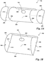
- FIG. 2A illustrates a side elevation of illuminator 100.
- reflector 102 includes a curved light-reflecting and/or light diffusing surface 202 with a semi-circular cross-section when viewed from the side.
- the semi-circular cross-section results in curved surface 202 being semi-cylindrical, in this case shaped like an open right semi-circular cylinder.
- Imaging aperture 101 can be formed in curved surface 202.
- Curved light-reflecting surface 202 is designed to reflect and/or diffuse incident light from interior light sources 108 and direct it out of the illuminator through opening 112.
- Curved surface 202 has a height H and width W, both of which are chosen based on the particular application and its requirement.
- Light module 104 is positioned at the open end of reflector 102 such that interior light sources 108 will direct light toward the interior 201 of reflector 102, and thus toward surface 202. Exterior light sources 106 are on the opposite side of light module 104 and do not direct light toward the interior 201 of reflector 102, but instead direct their light into light pipe assembly 110.
- Light pipe assembly 110 is positioned over light module and aligned so that the light module is sandwiched between the light pipe assembly and the open end of reflector 102.
- the light pipe assembly can be held in place by fastening it to light module 104, for instance using flange 712 ( see Fig. 7 ), but in other embodiments it can also be secured by attaching it to reflector 102.
- Light pipe assembly 110 can also be attached by means of heat stakes positioned on the proximal end surfaces of segments 702, 704, 706 and 708.
- Cover 114 is positioned over opening 112 to prevent contaminants or other objects from entering the illuminator through opening 112 and damaging the components in it.
- cover 114 is shown mounted to the interior edges of light pipe assembly 110, in other embodiments cover 114 could be mounted to some other part of the illuminator.
- cover 114 is transparent and is very thin to avoid compromising the optical uniformity of the illuminator, but in other embodiments the thickness of cover 114 can be greater or smaller and cover 114 can be made of a translucent material to provide additional diffusion.
- cover 114 can be a composite that includes at least two different portions selected from transparent, translucent or opaque.
- cover 114 can include an anti-reflective coating on the inside, outside, or both the inside and the outside.
- Figure 2B illustrates a side elevation cross-section of illuminator 100.
- Curved light-reflecting surface 202 has a length L , meaning that reflective surfaces 206 and 210 are spaced apart by L ; as with the illuminator's height H and width W , length L can be chosen based upon the application requirements.
- light module 104 is positioned at the open end of reflector 102 such that interior light sources 108 can direct light toward the interior 201 of reflector 102, and thus toward surface 202.
- Exterior light sources 106 are on the opposite side of light module 104 and do not direct light toward the interior 201 of reflector 102, but instead direct their light into light pipe assembly 110.
- Light pipe assembly 110 is positioned over light module and aligned so that exterior light sources 106 will direct their light into the light pipe assembly, and cover 114 is positioned over opening 112 to prevent contaminants or other objects from entering the illuminator through opening 112 and damaging the components in it.
- FIGS 3A-3B together illustrate an embodiment of an reflector 102;
- Figure 1A illustrates an exploded view, while
- Figure 1B illustrates an assembled view.
- Reflector 102 includes curved light-reflecting surface 202 that is bounded by curved edges 302 and 304, as well as by longitudinal edges 306 and 308.
- curved edges includes any edge that is not a single straight line and includes, without limitation, curves that are smooth and continuous as well as curves made up of multiple straight or non-straight line segments, whether smooth and continuous or not.
- curved surface 202 is concave, but in other embodiments it can be convex or can be some combination of concave and convex.
- curved surface 202 is formed by bending a lamina into the appropriate shape.
- the lamina can be sheet metal, but in other embodiments a lamina made of other materials such as sheets of plastic or some kind of composite can be used.
- surface 202 can be formed differently.
- surface 202 can be machined out of a solid block of metal, plastic, wood, or some kind of composite.
- curved surface 202 should have the appropriate physical and/or optical properties-such as color, texture and reflectivity-to create the desired reflection and/or diffusion.
- the physical and/or optical characteristics of surface 202 can be matched to enhance or supplement the optical characteristics of interior light sources 208, but in other embodiments the physical and/or optical characteristics of surface 202 can be used to change of modify the optical characteristics of light emitted by interior light sources 108. For instance, in an embodiment where interior light sources 208 emit white light, by applying an appropriately colored coating to curved light-reflecting surface 202 the white light from interior light sources 208 can be filtered such that the color of light exiting the illuminator through opening 112 is not white.
- the material from which surface 202 is made may already have the correct physical and/or optical properties, such that no further processing is needed once curved light-reflecting surface 202 has been formed.
- the lamina could be of a plastic that already has the correct color, texture and reflectivity, meaning that nothing further needs to be done to the surface after it is formed.
- reflectivity or texture- such as when curved surface 202 is formed of metal-then additional treatment may be needed to give curved light-reflecting surface 202 the correct physical and/or optical properties.
- a coating such as paint can be applied to the surface.
- other treatments such as sheets of material with the correct physical and/or optical properties can be laid on curved light-reflecting surface 202 and secured with adhesive.
- Each of longitudinal edges 306 and 308 extends from an endpoint of edge curved edge 302 to a corresponding endpoint of curved edge 304 to form surface 202.
- curved edges 302 and 304 both have the same size and shape and longitudinal edges 306 and 308 are straight, meaning that surface 202 is semi-cylindrical and shaped substantially like an open right semi-circular cylinder.
- curved light-reflecting surface 202 results from translating curved edge 302 in a straight line through space until it reaches or becomes curved edge 304.
- curved edges 302 and 304 can have other shapes besides semi-circular ( see Figures 4A-4F ), and in still other embodiments curved edges 302 and 304 need not have the same size and/or shape, nor do longitudinal edges 306 and 308 need to have the same size and/or shape.
- End caps 204 and 208 are attached to curved edges 302 and 304 and should substantially cover the open ends of the curved light-reflecting surface 202.
- end caps 204 and 208 have substantially the same cross-sectional shape as the open ends of curved surface 202, but in other embodiments the end caps need not have exactly the same shape as the open ends.
- one or both of end caps 204 and 208 could be square, so long as they substantially cover the ends of curved surface 202.
- End caps 204 and 208 are positioned such that edges 310 and 312 are substantially co-planar with longitudinal edge 306 and 308, forming a lip to which light module 104 can be mounted.
- End cap 204 includes a reflective side 206 and end cap 208 includes a reflective side 210.
- End caps 204 and 208 are attached to the curved edges of surface 202 with their reflective surfaces 206 and 210 parallel or substantially parallel to each other and facing each other. In other embodiments, however, reflective surfaces 206 and 210 need not be parallel, but can be at an angle with respect to each other.
- reflective surfaces 206 and 210 are mirrors, but in other embodiments they can be other types of surface with reflectivities equal to or less than a mirror.
- reflective surfaces 206 and 210 are first-surface mirrors, meaning that the reflective surface must be the first surface encountered by incident light. In other embodiments other kinds of mirror can be used.
- Reflective surfaces 206 and 210 can be formed in different ways. For instance, if end caps 204 and 208 are metal, reflective surfaces 206 and 210 can be formed by polishing the appropriate surface of each end cap. In other embodiments, a reflective coating can be applied to end caps 204 and 208, for example by spraying or by securing a sheet of reflective materials to the appropriate surface of each end cap. In still other embodiments more sophisticated methods such as electrolytic plating can be used.
- Figure 3C illustrates an alternative embodiment of an reflector 300.
- Reflector 300 is similar in most respects to reflector 102, the principal difference between being the presence in illuminator 300 of multiple imaging apertures and/or apertures that are positioned off the vertex or cusp of surface 202. These can include apertures 302 that are positioned on or near the centerline ( e.g. , at or near the vertex or cusp) curved surface 202, as well as apertures 304 that are positioned off the vertex or cusp of surface 202.
- Figures 4A-4F illustrate cross-sections of various alternative embodiments of a reflector having different shapes for curved surface 202.
- Figure 4A illustrates an embodiment in which the two curved edges of curved surface 402 are semi-elliptical and symmetrical about centerline 401, making curved surface 402 an open right semi-elliptical cylinder with its apex or cusp 404 aligned with the centerline.
- Figure 4B illustrates an embodiment in which the two curved edges of curved surface 406 are parabolic and symmetrical about centerline 401, making the curved surface an open right parabolic cylinder its apex or cusp 408 aligned with the centerline.
- Figure 4C illustrates an embodiment in which the curved edges of curved surface 410 are square and symmetrical about centerline 401, making curved surface 410 an open right square cylinder with its apex or cusp 412 aligned with centerline 401.
- Figure 4D illustrates an embodiment in which the two curved edges of curved surface 414 are faceted ( i.e., made up of a plurality of line segments) and symmetrical about centerline 401, making curved surface 414 an open right faceted cylinder with its apex or cusp 416 aligned with centerline 401.
- Figure 4E illustrates an embodiment in which the curved edges of curved surface 418 are skewed parabolas that are not symmetrical about centerline 401, making curved surface a skewed right parabolic cylinder with its apex or cusp offset from centerline 401.
- Figure 4F illustrates an embodiment in which the curved edges of curved surface 422 are compound curves, such as the illustrated M-shaped curve 422 that is symmetric about centerline 401 and has two cusps 426 and 428.
- the curve need not be symmetrical about centerline 401.
- the compound curve 422 can be skewed as shown in Figure 4E , or the cusps 426 and 428 need not have the same height.
- Figures 4A-4F are not intended to present an exhaustive catalog of possible shapes for a curved surface.
- other shapes besides those shown can be used.
- any polynomial function can be used to form a curved surface, while in other embodiments other types of functions-such as exponential, logarithmic or hyperbolic functions-can be used.
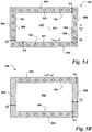
- Figures 5A-5B illustrate an embodiment of a light module 104;
- Figure 5A illustrates the side with the exterior light sources, while
- Figure 5B illustrates the opposite side with the interior light sources.
- Light module 104 is formed from a substrate and is shaped like a rectangular annulus made up of four segments 502, 504, 506 and 508.
- the shape and exterior dimensions of the annulus can correspond to shape and size of the open end of reflector 102, but in other embodiments light module 104 can have a different shape and/or size than the opening of reflector 102.
- light module 104 can include a greater or lesser number of segments and can have a different shape and size than shown.
- the substrate used to form the rectangular annulus is a single- or multi-layered printed circuit board, but in other embodiments other substrates such as plastics or metals can be used.
- segment 502-508 has an interior edge: segment 502 has an interior edge 503, segment 504 has an interior edge 505; segment 506 has an interior edge 507 and segment 508 has an interior edge 509. Interior edges 503-509 form the boundary of opening 510 in the middle of the rectangular annulus. Segments 502-508 have widths F1-F4, respectively, which are chosen based on the requirements of light sources 106 and 108, as well as the required size of opening 510. In the illustrated embodiment widths F1-F4 are equal, but in other embodiments widths F1-F4 need not be equal.
- Exterior light sources 106 are positioned and mounted along segments that form the rectangular annulus. In the illustrated embodiment exterior light sources 106 are positioned on all four segments 502-508 such that there are light sources all the way around opening 510, but in other embodiments there need not be light sources present on all the segments. The type and number of exterior light sources 106 will depend on the type of light source used, as well as the power requirements of the application and the desired lighting characteristics such as color and uniformity. In one embodiment exterior light sources 106 can be light emitting diodes (LEDs), but in other embodiments exterior light sources 106 can be another type of light source, such as incandescent or halogen light bulbs.
- LEDs light emitting diodes
- exterior light sources 106 need not all be the same kind, but can instead include combinations of two or more different types of light source.
- the spacing s LP between exterior light sources 106 will generally depend on the number of exterior light sources and the length of the segment on which they are mounted.
- the illustrated embodiment shows light sources 106 uniformly spaced at a fixed interval s LP , but in other embodiments the exterior light sources need not be uniformly spaced.
- light module 104 can also include provisions, such as traces on a printed circuit board, for routing electrical power to exterior light sources 106.
- Figure 5B illustrates the side of light module 104 having interior light sources 108; in most embodiments, this will be the side of light module 104 opposite the side with exterior light sources 106.
- interior light sources 108 are positioned only on segments 502 and 506, although in other embodiments interior light sources can be present on a greater or lesser number of segments.
- the type and number of interior light sources 108 will depend on the type of light source used, as well as the power requirements of the application and the desired lighting characteristics such as color and uniformity.
- interior light sources 108 can be light emitting diodes (LEDs), but in other embodiments interior light sources 108 can be another type of light source, such as incandescent or halogen light bulbs.
- interior light sources 108 need not all be the same kind, but can instead include combinations of two or more different types of light source.
- the spacing s D between light sources will generally depend on the number of interior light sources 108 and the length of the segment on which they are mounted.
- the illustrated embodiment shows light sources 108 uniformly spaced at a fixed interval s D , but in other embodiments interior light sources 108 need not be uniformly spaced.
- light module 104 can also include provisions, such as traces on a printed circuit board, for routing electrical power to interior light sources 108.
- Figures 6A-6C illustrate alternative embodiments of edge treatments for interior edges 503-509 of light module 104.
- Figure 6A illustrates an embodiment 600 in which segments 502, 504, 506 and 508 are substantially flat and have widths F1-F4, respectively.
- edges 503, 505, 507 and 509 require no special treatment, but widths F1-F4 should be sized so that no direct light from interior light sources 108 exits the illuminator through opening 110 ( see, e.g., Fig. 2A ) and no light from exterior light sources 106 enters the reflector.
- Figure 6B illustrates an alternative embodiment 625 in which edges 503, 505, 507 and 509 can include one or both of an upturned portion 602 and a downtumed portion 604.
- Upturned portion 602 and downturned portion 604 can help in preventing light from interior light sources 108 from directly exiting the illuminator through opening 120 and preventing light from exterior light sources 106 from entering enters the reflector (see, e.g., Fig. 2A ). With the presence of upturned portion 602 and downturned portion 604, it can also be possible to reduce the widths F1-F4 of segments 502, 504, 506 and 508.
- upturned portion 602 and downturned portion 604 can run along the entire length of an edge, but in other embodiments they can run along only a portion of an edge. In some embodiments of light module 104, one or both of upturned portion 602 and downturned portion 604 can be present along some edges but not others.
- FIG. 6C illustrates an alternative embodiment 650 in which each edge 503, 505, 507 and 509 can include one or both of an upper baffle 606 and a lower baffle 608.
- baffles 606 and 608 can be made of an opaque material, but in other embodiments the baffles can be made of a translucent or transparent material or can be made of some combination of two or more of opaque, translucent or transparent material. In other embodiments, both baffles need not be made of the same materials.
- baffles 606 and 608 By correctly sizing, positioning and choosing materials for baffles 606 and 608, the baffles can help in preventing light from interior light sources 108 from directly exiting the illuminator through opening 120 and preventing light from exterior light sources 106 from entering enters the reflector ( see, e.g., Fig. 2A ).
- the presence of baffles 606 and 608 can also make it possible to reduce the widths F1-F4 of segments 502, 504, 506 and 508.
- baffles can run along the entire length of an edge, but in other embodiments baffles can be present only along portions of an edge. In some embodiments of light module 104, one or both of baffles 606 and 608 can be present along some edges but not others.
- Figures 7A-7B illustrate an embodiment of light pipe assembly 110;
- Figure 7A is a plan view, while Figure 7B is a sectional view.
- light pipe assembly 110 is shaped like a rectangular annulus made up of four light pipe segments 702, 704, 706 and 708 whose ends connect such that the segments are at right angles to each other. Segments 702-708 surround an opening 710, thus forming the rectangular annulus.
- light pipe assembly 110 that includes more than one light pipe segment light pipe segments 702-708 can all have the same cross-sectional shape ( see Fig. 7B ), but in other embodiments light pipe segments 702-708 need not all have the same cross-sectional shape.
- light pipe assembly 110 can include a greater or lesser number of segments.
- light pipe assembly 110 can be made up of one or more unconnected light pipe segments.
- light pipe assembly 110 can be made of an optically transparent material such as glass or plastic, but in other embodiments in which diffusion is desired the light pipes can be made of a translucent material or can be made of a transparent material with surfaces treated to create diffusion.
- Flange 712 is positioned at or near the perimeter of opening 710 on the side of light pipe assembly 110 that will face light module 104.
- the external dimensions of flange 712 can substantially correspond to the internal dimensions of opening 510 of light module 104, so that flange 712 engages with edges 503, 505, 507 and 509 to hold light pipe assembly 110 in place.
- flange 712 need not be present and light pipe assembly 110 can be held in place by other means such as fasteners or adhesives.
- both flange 712 and other means can be used together to hold light pipe assembly in place.
- the shape and exterior dimensions of light pipe assembly 110 substantially correspond to the shape and size of light module 104, but in other embodiments light module 104 can have a different shape and/or dimensions than the light module. For instance, in an embodiment of light module 104 that does not have exterior light sources 106 on every segment 502, 504, 506 and 508, the light pipe assembly would only need to have light pipe segments corresponding to the segments of the light module with exterior light sources.
- Figure 7B illustrates an embodiment of the cross-section of light pipe assembly 110, as well as an embodiment of the cross sections of individual light pipe segments 704 and 708 within the light pipe assembly.
- Flange 712 projects from the side of the light pipe assembly that will be coupled to light module 104 and, in embodiment where it is present, helps to align the light pipe assembly with the light module and hold the two together as described above.
- Light pipe segment 704 includes a proximal end 713 through which light is launched into the light pipe segment by exterior light sources 106, as shown by the arrows.
- Light pipe segment 704 also includes a distal tip 716. Between proximal end 713 and distal tip 716, light pipe segment 704 has a constant cross-section portion 714, as well as a tapered portion 715 formed by surfaces Z1 and Z2 that are at an angle ⁇ with respect to each other.
- tapered portion 715 has a taper ratio (the ratio of the smallest width to the largest width in the tapering portion) of zero, meaning it tapers to a sharp tip. In other embodiments, however, the light pipe segment can have a non-zero taper ratio.
- a certain portion of the light launched into proximal end 713 will exit the light pipe segment through surface Z1, while a certain amount will exit through surface Z2, as shown in the figure for segment 708.
- the relative magnitudes of the two portions can be changed by adjusting the size, shape and material of the light pipe assembly or the individual light pipe segments.
- Figure 7C-7E illustrate alternative embodiments of cross-sectional shapes for individual light pipes in light pipe assembly 110.
- Figure 7C illustrates a double-tapered light pipe that includes portions having different taper ratios. One tapered portion is formed by surfaces Z1 and Z2a, which are at an angle ⁇ 2 with respect to each other, while the other tapered portion is formed by surfaces Z1 and Z2b, which are at an angle ⁇ 1 relative to each other.
- the illustrated embodiment tapers to a sharp tip, but as with light pipe segment 704, it need not taper to a sharp tip.
- Figure 7D illustrates an embodiment in which the light pipe segment is tapered by making surface Z1 planar while making surface Z2 curved.
- Figure 7E illustrates an embodiment in which surface Z2 is planar, while surfaces Z1a and Z1b are positioned at different angles relative to surface Z2.
- Figures 8A-8D illustrate an embodiment of the operation of an imaging system 50 using illuminator 100.
- Figure 8A illustrates use of the dark field mode of the illuminator.
- Illuminator 100 is position such that the tips of light pipe assembly 110 are in contact with a surface 802 and such that the light pipe assembly surrounds an object to be imaged.
- Exterior light sources 106 are turned on, launching light into light pipe assembly 110. Light travels through each light pipe segment and exits through surface Z1 at a low angle ⁇ 0 relative to surface 802.
- ⁇ 0 has a value of approximately 5 degrees, but in other embodiments the shape, size and material of the light pipes can be adjusted to make ⁇ 0 larger or smaller. In different embodiments, for example, ⁇ 0 can be between about zero and about 20 degrees.
- Figure 8B illustrates an embodiment in which the imaging system 50 is held so that the tips of light pipe assembly 110 are held at a finite height HI above surface 802.
- H1 is approximately 0,635 cm (0.25 inches)
- ⁇ 1 can be about 30 degrees
- H1 is approximately 1,27 cm (0.5 inches)
- ⁇ 1 can be about 45 degrees.
- the shape, size and material of the light pipes can be adjusted to make ⁇ 1 larger or smaller for a given H1.
- Figure 8C illustrates an embodiment in which the imaging system 50 is held so that the tips of light pipe assembly 110 are held at a finite height H2 above surface 802, where H2 is substantially greater than HI shown in Figure 8B .
- H2 is substantially greater than HI shown in Figure 8B .
- light exiting through both surface Z1 and Z2 of each light pipe impinges on surface 802 in the field of view of camera 52.
- about half the light exits through each surface i.e., 50% through Z1 and 50% through Z2
- the fraction of light exiting through each surface can be adjusted by adjusting the shape, size and materials of the light pipe assembly.
- illuminator 100 can provide ⁇ degrees of forward-emitting general purpose lighting that can be used, for instance, for far range imaging.
- ⁇ has a value of about 40 degrees, but angle ⁇ can be adjusted by adjusting the shape, size and materials of the light pipe assembly.
- Figure 8D illustrate an embodiment in which imaging system 50 uses its bright field capabilities. Exterior lights 106 are turned off and interior lights 108 are turned on, such that light from interior lights 108 is reflected off the curved reflecting surface of reflector and is directed out of the illuminator through opening 112. If appropriately made or treated, the reflective surface of reflector 120 can also be used to diffuse light in addition to reflecting it, thus providing uniform of forward-emitting general purpose lighting that can be used for bright field imaging.
- Imaging system 900 includes camera 904 and illuminator 100; of course, in other embodiments of imaging system 900 the illuminator 100 can be replaced with any of the other illuminator embodiments described herein.
- Imaging system 900 includes a housing 902 within which are positioned illuminator 100 and camera 904.
- imaging system 900 includes a signal conditioner 912 coupled to image sensor 910, a processor 914 coupled to signal conditioner 912, and an input/output unit 916 coupled to processor 914.
- an internal or external power supply provides electrical power to the components within housing 902.
- imaging system 900 can be a small portable handheld system, but in other embodiments it can be a fixed-mount imaging system.
- Illuminator 100 is positioned within housing 902 such that opening 112 will face toward an object to be illuminated and imaged.
- the object to be illuminated and images is an optical symbol such as a bar code or matrix code 918 on a surface 920, but in other embodiments the object can be a part or surface of a part that is subject to machine vision inspection.
- Interior lights 108 or exterior lights 106 are turned on, as appropriate, to illuminate object 918 on surface 920.
- Camera 904 includes optics 908 coupled to an image sensor 910.
- optics 908 include one or more refractive lenses, but in other embodiment optics 908 can include one or more of refractive, reflective or diffractive optics.
- image sensor 910 includes a CMOS image sensor, although in other embodiments different types of image sensors such as CCDs can be used.
- Image sensor 910 and optics 908 are positioned within housing 902 such that optics 908 are optically aligned with imaging aperture 101 in curved surface 202. Optically aligning optics 908 with imaging aperture 101 allows optics 908 to focus an image of object 918 onto image sensor 910, enabling image sensor 910 to capture an image of object 918 while illuminator 100 simultaneously illuminates the object.
- Signal conditioner 912 is coupled to image sensor 910 to receive and condition signals from a pixel array within image sensor 910.
- signal conditioner 912 can include various signal conditioning components such as filters, amplifiers, offset circuits, automatic gain control, analog-to-digital converters (ADCs), digital-to-analog converters, etc.
- Processor 914 is coupled to signal conditioner 912 to receive conditioned signals corresponding to each pixel in the pixel array of image sensor 910.
- Processor 914 can include a processor and memory, as well as logic or instructions to process the image data to produce a final digital image and to analyze and decode the final image.
- processor 914 can be a general-purpose processor, while in other embodiments it can be an application specific integrated circuit (ASIC) or a field-programmable gate array (FPGA). Processor 914 can also be coupled to image sensor 910 to monitor its function and/or provide a control signal for it to alter its function.
- ASIC application specific integrated circuit
- FPGA field-programmable gate array
- Input/output circuit 916 is coupled to processor 914 to transmit the image and/or information decoded from the image to other components (not shown) that can store, display, further process, or otherwise use the image data or the decoded information.
- input/output circuit 916 can include a processor, memory, storage, and hardwired or wireless connections to one or more other computers, displays or other components.
- elements 912, 914 and 916 are shown co-housed with camera 901 and illuminator 100, but in other embodiments, elements 912, 914 and 916 can be positioned outside housing 902. In still other embodiments one or more of elements 912, 914 and 916 can be integrated within image sensor 910.
Landscapes
- Physics & Mathematics (AREA)
- General Physics & Mathematics (AREA)
- Optics & Photonics (AREA)
- Engineering & Computer Science (AREA)
- General Engineering & Computer Science (AREA)
- Non-Portable Lighting Devices Or Systems Thereof (AREA)
Claims (16)
- Vorrichtung, die Folgendes umfasst:einen gebogenen Reflektor (102), der einen Innenraum und ein offenes Ende aufweist,wobei der gebogene Reflektor ein halbzylinderförmiger Reflektor ist, der Folgendes umfasst:eine gebogene diffus reflektierende Oberfläche (202), die durch ein Paar gegenüberliegender gebogener Kanten (302, 304) und ein Paar gegenüberliegender Längskanten (306, 308), die sich zwischen jeweiligen Endpunkten der gegenüberliegenden gebogenen Kanten erstrecken, begrenzt ist; undein paralleles Paar planer Spiegelflächen (204, 208), wobei jede plane Spiegelfläche an einer entsprechenden der gebogenen Kanten befestigt ist und wobei jede plane Spiegelfläche eine gerade Kante (310, 312) in derselben Ebene wie die einander gegenüberliegenden Längskanten aufweist;ein Lichtmodul (104), das um einen Umriss des offenen Endes des halbzylinderförmigen Reflektors positioniert ist, wobei das Lichtmodul eine erste Seite, die eine oder mehrere innere Lichtquellen (108) aufweist, um Licht auf den Innenraum des halbzylinderförmigen Reflektors zu richten, und eine zweite Seite gegenüber der ersten Seite, die eine oder mehrere äußere Lichtquellen (106) aufweist, um Licht weg von dem Innenraum des halbzylinderförmigen Reflektors zu richten, umfasst; undeinen Hohllichtleiter (110), der mit dem Lichtmodul gekoppelt ist und so ausgerichtet ist, dass Licht von der einen oder den mehreren äußeren Lichtquellen in ein Ende des Hohllichtleiters geführt wird und durch das andere Ende des Hohllichtleiters austritt.
- Vorrichtung nach Anspruch 1, wobei die gebogene lichtreflektierende Oberfläche eine Beschichtung aufweist, die Licht streut.
- Vorrichtung nach Anspruch 1, wobei die Formen der gegenüberliegenden gebogenen Kanten halbkreisförmig, parabolisch, hyperbolisch, halb ellipsenförmig oder schräg parabolisch sind.
- Vorrichtung nach Anspruch 1, die ferner eine Abbildungsöffnung (101) in dem gebogenen Reflektor aufweist.
- Vorrichtung nach Anspruch 1, wobei das Lichtmodul ein rechteckiger Kranz ist.
- Vorrichtung nach Anspruch 5, wobei die eine oder die mehreren inneren Lichtquellen nur entlang zweier gegenüberliegender Kanten des rechteckigen Kranzes positioniert sind.
- Vorrichtung nach Anspruch 6, wobei die eine oder die mehreren äußeren Lichtquellen entlang aller vier Kanten (503, 505, 507, 509) des rechteckigen Kranzes positioniert sind.
- Vorrichtung nach Anspruch 1, wobei der Hohllichtleiter wie ein rechteckiger Kranz geformt ist und vier Segmente umfasst.
- Vorrichtung nach Anspruch 8, wobei jedes Segment des Hohllichtleiters zwischen einem proximalen Ende, das bei den äußeren Lichtquellen positioniert ist, und einer distalen Spitze, die von dem proximalen Ende beabstandet ist, konisch zuläuft.
- System, das Folgendes umfasst:eine Vorrichtung nach einem der Ansprüche 1 bis 9, undeine Kamera (904), die Abbildungsoptiken enthält, die mit einer Abbildungsöffnung in dem gebogenen Reflektor optisch gekoppelt ist.
- System nach Anspruch 10, das ferner eine Signaleingabeschaltung (912) umfasst, die mit der Kamera gekoppelt ist.
- System nach Anspruch 11, das ferner einen Prozessor (914) umfasst, der mit der Signaleingabeeinheit und der Kamera gekoppelt ist.
- System nach Anspruch 12, das ferner eine Eingabe- bzw. Ausgabeeinheit (916) umfasst, die mit dem Prozessor gekoppelt ist.
- Verfahren zum Herstellen einer Vorrichtung nach einem der Ansprüche 1 bis 9, das die folgenden Schritte umfasst:Ausbilden eines gebogenen Reflektors (102), der einen Innenraum und ein offenes Ende aufweist; wobei der gebogene Reflektor ein halbzylinderförmiger Reflektor ist, der Folgendes umfasst:eine gebogene diffus reflektierende Oberfläche (202), die ein Paar gegenüberliegender gebogener Kanten (302, 304) und ein Paar gegenüberliegender Längskanten (306, 308) aufweist, die sich zwischen jeweiligen Endpunkten der gegenüberliegenden gebogenen Kanten erstrecken; undein paralleles Paar planer Spiegelflächen (204, 208), wobei jede plane Spiegelfläche an einer entsprechenden der gebogenen Kanten befestigt ist und wobei jede plane Spiegelfläche eine gerade Kante (310, 312) in derselben Ebene wie die einander gegenüberliegenden Längskanten aufweist;Positionieren eines Lichtmoduls um einen Umriss des offenen Endes des Reflektors, wobei das Lichtmodul eine erste Seite, die eine oder mehrere innere Lichtquellen aufweist, um Licht zu dem Innenraum des Reflektors zu richten, und eine zweite Seite, die eine oder mehrere äußere Lichtquellen aufweist, um Licht weg von dem Reflektor zu richten, umfasst; undKoppeln eines Hohllichtleiters mit dem Lichtmodul und Ausrichten des Hohllichtleiters, so dass Licht von der einen oder den mehreren äußeren Lichtquellen in den Hohllichtleiter geführt wird.
- Verfahren nach Anspruch 14, das ferner den Schritt des Abscheidens einer Beschichtung, die Licht streut, auf der gebogenen Licht reflektierenden Oberfläche umfasst.
- Verfahren nach Anspruch 14, das ferner den Schritt des Ausbildens einer Abbildungsöffnung in dem gebogenen Reflektor umfasst.
Applications Claiming Priority (2)
| Application Number | Priority Date | Filing Date | Title |
|---|---|---|---|
| US12/501,325 US8107808B2 (en) | 2009-07-10 | 2009-07-10 | Combination dark field and bright field illuminator |
| PCT/US2010/039550 WO2011005545A2 (en) | 2009-07-10 | 2010-06-22 | Combination dark field and bright field illuminator |
Publications (3)
| Publication Number | Publication Date |
|---|---|
| EP2452121A2 EP2452121A2 (de) | 2012-05-16 |
| EP2452121A4 EP2452121A4 (de) | 2016-07-13 |
| EP2452121B1 true EP2452121B1 (de) | 2018-08-15 |
Family
ID=43427543
Family Applications (1)
| Application Number | Title | Priority Date | Filing Date |
|---|---|---|---|
| EP10797584.9A Active EP2452121B1 (de) | 2009-07-10 | 2010-06-22 | Kombinierter dunkelfeld- und hellfeld-beleuchter |
Country Status (5)
| Country | Link |
|---|---|
| US (1) | US8107808B2 (de) |
| EP (1) | EP2452121B1 (de) |
| KR (1) | KR20120046220A (de) |
| CN (1) | CN102472474B (de) |
| WO (1) | WO2011005545A2 (de) |
Families Citing this family (24)
| Publication number | Priority date | Publication date | Assignee | Title |
|---|---|---|---|---|
| US8032017B2 (en) * | 2006-09-29 | 2011-10-04 | Microscan Systems, Inc. | Methods for providing diffuse light |
| US7978970B2 (en) * | 2006-09-29 | 2011-07-12 | Microscan Systems, Inc. | Systems and/or devices for providing diffuse light |
| US8374498B2 (en) * | 2006-09-29 | 2013-02-12 | Microscan Systems, Inc. | Systems and/or devices for camera-based inspections |
| US8000594B2 (en) * | 2009-07-02 | 2011-08-16 | Microscan Systems, Inc. | Diffuse reflective illuminator |
| US8768159B2 (en) | 2009-07-10 | 2014-07-01 | Microscan Systems, Inc. | Combination dark field and bright field illuminator |
| US8184158B2 (en) * | 2009-10-28 | 2012-05-22 | Chen Kun-Sen | Curved mirror camera |
| DE102010014099A1 (de) * | 2010-04-07 | 2011-10-13 | Siteco Beleuchtungstechnik Gmbh | Leuchte mit Abdeckscheibe |
| US10498933B2 (en) | 2011-11-22 | 2019-12-03 | Cognex Corporation | Camera system with exchangeable illumination assembly |
| US20140071673A1 (en) | 2012-09-11 | 2014-03-13 | Abl Ip Holding Llc | Recessed Luminaire |
| CN104568980A (zh) * | 2014-12-30 | 2015-04-29 | 苏州巨能图像检测技术有限公司 | Aoi检测装置 |
| CN104696900B (zh) * | 2015-03-31 | 2018-01-30 | 合肥鑫晟光电科技有限公司 | 光源装置及对位标记照相识别系统 |
| US9569653B1 (en) | 2016-06-13 | 2017-02-14 | Datalogic IP Tech, S.r.l. | Dark field illumination system obtained in a tilted plane |
| EP3629224B1 (de) * | 2016-10-12 | 2023-06-21 | Hand Held Products, Inc. | Mobiler bildgebender barcodescanner |
| CN107944315B (zh) | 2016-10-12 | 2023-08-04 | 手持产品公司 | 移动成像条形码扫描仪 |
| DE102017118246A1 (de) | 2017-08-10 | 2019-02-14 | Ioss Intelligente Optische Sensoren & Systeme Gmbh | Bildaufnahmevorrichtung |
| CN109424871B (zh) * | 2017-08-18 | 2023-05-05 | 手持产品公司 | 用于条码扫描器的照明器 |
| US10674055B2 (en) * | 2017-08-29 | 2020-06-02 | Omron Corporation | Apparatus for detecting, reading, and verifying 1-D, 2-D, and DPM symbologies |
| US10650205B2 (en) | 2018-09-28 | 2020-05-12 | Hand Held Products, Inc. | Methods, systems, and apparatuses for scanning and decoding direct part marking indicia |
| LU101861B1 (en) * | 2020-06-17 | 2021-12-17 | Virelux Inspection Systems Sarl | Dynamic illumination inspection tunnel |
| EP4198627B1 (de) * | 2020-12-30 | 2026-04-15 | Hangzhou Hikvision Digital Technology Co., Ltd. | Lichtergänzende lampe für halbkugelförmige kamera und halbkugelförmige kamera |
| US12175323B2 (en) * | 2022-03-16 | 2024-12-24 | Hand Held Products, Inc. | Camera reader apparatuses and methods of using the same |
| US11960968B2 (en) * | 2022-08-25 | 2024-04-16 | Omron Corporation | Scanning device utilizing separate light pattern sequences based on target distance |
| US12339112B2 (en) | 2022-08-25 | 2025-06-24 | Omron Corporation | Symbology or frame rate changes based on target distance |
| US12118428B2 (en) | 2022-08-25 | 2024-10-15 | Omron Corporation | Using distance sensor delta to determine when to enter presentation mode |
Family Cites Families (106)
| Publication number | Priority date | Publication date | Assignee | Title |
|---|---|---|---|---|
| US568453A (en) * | 1896-09-29 | Cattle-guard machine | ||
| US2357378A (en) | 1941-12-01 | 1944-09-05 | Bausch & Lomb | Microscope illuminator |
| US3614449A (en) * | 1969-02-12 | 1971-10-19 | Itt | Optical tracking system utilizing a coaxial lens system |
| US3726998A (en) | 1971-08-09 | 1973-04-10 | Phonocopy Inc | Light pipe illuminated scan reader |
| US3857626A (en) | 1971-12-10 | 1974-12-31 | Bausch & Lomb | Microscope coaxial illumination apparatus |
| US3918028A (en) | 1973-01-05 | 1975-11-04 | Data Source Corp | Hand held optical reader |
| US4099221A (en) * | 1976-06-29 | 1978-07-04 | The Raymond Lee Organization, Inc. | Portable ceiling reflector for photography |
| US4128298A (en) | 1976-12-27 | 1978-12-05 | Recognition Equipment Incorporated | Wand nose with integral light pipe for wand power turn-on |
| JPS582501B2 (ja) | 1978-03-03 | 1983-01-17 | 株式会社日立製作所 | 受光素子 |
| JPS5642217A (en) | 1979-09-14 | 1981-04-20 | Nippon Kogaku Kk <Nikon> | Diaphragm device of lens that can make close-up flash photographing |
| DE3100662A1 (de) | 1980-01-31 | 1981-11-26 | Jenoptik Jena Gmbh, Ddr 6900 Jena | "vorrichtung zur dunkelfeldbeleuchtung in auflichtmikroskopen" |
| JPS57150812A (en) | 1981-03-13 | 1982-09-17 | Olympus Optical Co Ltd | Dark field illuminating optical system |
| JPS5828712A (ja) | 1981-08-13 | 1983-02-19 | Olympus Optical Co Ltd | 暗視野照明用光学系 |
| US4767172A (en) | 1983-01-28 | 1988-08-30 | Xerox Corporation | Collector for an LED array |
| JPS60104929A (ja) * | 1983-11-11 | 1985-06-10 | Yutaka Terashita | 撮影照明用リフレクタ |
| US4626079A (en) | 1984-04-13 | 1986-12-02 | Nippon Kogaku K.K. | Dark field illumination apparatus for epi-illumination system |
| US4653875A (en) * | 1984-11-02 | 1987-03-31 | Hines Stephen P | Infinity display apparatus using cylindrical beam-splitters |
| DE3477271D1 (en) | 1984-12-28 | 1989-04-20 | Ibm | Waveguide for an optical near-field microscope |
| JPS61270720A (ja) | 1985-05-25 | 1986-12-01 | Nippon Kogaku Kk <Nikon> | 暗視野照明装置 |
| GB8603507D0 (en) | 1986-02-13 | 1986-03-19 | Emi Plc Thorn | Airport lighting device |
| EP0356680A1 (de) | 1988-08-11 | 1990-03-07 | Siemens Aktiengesellschaft | Optische Aufnahmeeinrichtung für Bildverarbeitungssysteme |
| US4930872A (en) * | 1988-12-06 | 1990-06-05 | Convery Joseph J | Imaging with combined alignment fixturing, illumination and imaging optics |
| US5177346A (en) | 1989-12-13 | 1993-01-05 | Computer Identics | Bar code reader system for reading bar code labels with a highly specular and low contrast surface |
| US5149948A (en) | 1990-07-16 | 1992-09-22 | Computer Identics | Improved bar code reader system for reading bar codes under high specular reflection conditions with a variety of surface effects |
| US5191199A (en) | 1990-12-12 | 1993-03-02 | Ncr Corporation | Bar code scanner support member |
| US5574804A (en) | 1990-12-21 | 1996-11-12 | Olschafskie; Francis | Hand-held scanner |
| US5172005A (en) * | 1991-02-20 | 1992-12-15 | Pressco Technology, Inc. | Engineered lighting system for tdi inspection comprising means for controlling lighting elements in accordance with specimen displacement |
| JP2873410B2 (ja) | 1991-02-25 | 1999-03-24 | 東京エレクトロン株式会社 | 被試料体の記号・文字識別装置 |
| US5161874A (en) | 1991-05-22 | 1992-11-10 | Mitchell C. Radov | Remote illumination system |
| US5378883A (en) | 1991-07-19 | 1995-01-03 | Omniplanar Inc. | Omnidirectional wide range hand held bar code reader |
| US5332892A (en) | 1991-07-25 | 1994-07-26 | Symbol Technologies, Inc. | Optical systems for bar code scanners |
| US5349172A (en) | 1992-02-27 | 1994-09-20 | Alex Roustaei | Optical scanning head |
| US5354977A (en) | 1992-02-27 | 1994-10-11 | Alex Roustaei | Optical scanning head |
| US5331176A (en) | 1992-04-10 | 1994-07-19 | Veritec Inc. | Hand held two dimensional symbol reader with a symbol illumination window |
| US5274228A (en) | 1992-06-01 | 1993-12-28 | Eastman Kodak Company | Linear light source/collector with integrating cylinder and light pipe means |
| CA2097360A1 (en) | 1992-06-03 | 1993-12-04 | Paul Dvorkis | Optical readers |
| US5362953A (en) | 1992-08-18 | 1994-11-08 | Intermec Corporation | Reading apparatus with separate illumination and detection optical axes |
| US5550362A (en) | 1992-11-20 | 1996-08-27 | Intermec Corporation | Method and apparatus for calibrating a bar code scanner |
| US5515452A (en) | 1992-12-31 | 1996-05-07 | Electroglas, Inc. | Optical character recognition illumination method and system |
| US5349210A (en) | 1993-02-02 | 1994-09-20 | Motorola, Inc. | Optical reading head with angled array |
| US5461417A (en) | 1993-02-16 | 1995-10-24 | Northeast Robotics, Inc. | Continuous diffuse illumination method and apparatus |
| US5408084A (en) | 1993-02-18 | 1995-04-18 | United Parcel Service Of America, Inc. | Method and apparatus for illumination and imaging of a surface using 2-D LED array |
| US5399852A (en) | 1993-02-19 | 1995-03-21 | United Parcel Service Of America, Inc. | Method and apparatus for illumination and imaging of a surface employing cross polarization |
| US5406060A (en) | 1993-05-06 | 1995-04-11 | Opticon Inc. | Bar code reader for sensing at an acute angle |
| US5497267A (en) | 1993-05-21 | 1996-03-05 | Mitsubishi Chemical Corporation | Video microscope |
| US5697699A (en) | 1993-09-09 | 1997-12-16 | Asahi Kogaku Kogyo Kabushiki Kaisha | Lighting apparatus |
| JP2740727B2 (ja) | 1993-09-27 | 1998-04-15 | 株式会社テック | シンボル読取装置 |
| US5481101A (en) | 1993-12-10 | 1996-01-02 | Teiryo Sangyo Co., Ltd. | Two dimensional code data reading apparatus and method |
| US5656803A (en) | 1994-04-11 | 1997-08-12 | Asahi Kogaku Kogyo Kabushiki Kaisha | Encoded symbol reader |
| US5586212A (en) | 1994-07-06 | 1996-12-17 | Hewlett-Packard | Optical wave guide for hand-held scanner |
| DE4424344A1 (de) | 1994-07-11 | 1996-01-18 | Nath Guenther | Beleuchtungsgerät |
| US5572006A (en) | 1994-07-26 | 1996-11-05 | Metanetics Corporation | Automatic exposure single frame imaging systems |
| KR100193372B1 (ko) | 1994-08-22 | 1999-06-15 | 가시오 가즈오 | 휴대형 스캐너 |
| US5506929A (en) | 1994-10-19 | 1996-04-09 | Clio Technologies, Inc. | Light expanding system for producing a linear or planar light beam from a point-like light source |
| US5604550A (en) * | 1994-10-31 | 1997-02-18 | Northeast Robotics, Inc. | Illumination device for indirectly illuminating an object with continuous diffuse light |
| US5761540A (en) * | 1994-10-31 | 1998-06-02 | Northeast Robotics, Inc. | Illumination device with microlouver for illuminating an object with continuous diffuse light |
| US5539485A (en) | 1994-10-31 | 1996-07-23 | White; Timothy P. | Illumination device for providing continuous diffuse light on and off an observing axis |
| US5506663A (en) | 1994-11-07 | 1996-04-09 | Xerox Corporation | Scanner mounting apparatus for an electrostatographic printing machine |
| US5786586A (en) | 1995-01-17 | 1998-07-28 | Welch Allyn, Inc. | Hand-held optical reader having a detachable lens-guide assembly |
| US5569902A (en) | 1995-01-17 | 1996-10-29 | Welch Allyn, Inc. | Contact two-dimensional bar code reader having pressure actuated switch |
| US5619029A (en) | 1995-04-04 | 1997-04-08 | Rockwell International Corporation | Imaging enhancement for touch cameras |
| FR2734932B1 (fr) | 1995-06-02 | 2001-10-26 | Asahi Optical Co Ltd | Dispositif de lecture de symboles de donnees |
| JP3431351B2 (ja) | 1995-06-05 | 2003-07-28 | ペンタックス株式会社 | データシンボル読み取り装置 |
| US5691773A (en) | 1995-09-12 | 1997-11-25 | Metanetics Corporation | Anti-hand-jittering dataform readers and methods |
| US5859418A (en) | 1996-01-25 | 1999-01-12 | Symbol Technologies, Inc. | CCD-based bar code scanner with optical funnel |
| JP3793600B2 (ja) | 1996-02-20 | 2006-07-05 | 株式会社オプトエレクトロニクス | 光学的パターン読取装置 |
| US5690417A (en) | 1996-05-13 | 1997-11-25 | Optical Gaging Products, Inc. | Surface illuminator with means for adjusting orientation and inclination of incident illumination |
| US5923022A (en) | 1997-04-14 | 1999-07-13 | Intermec Ip Corp. | Method and apparatus for identifying bar code symbols using reading gates |
| US6022124A (en) | 1997-08-19 | 2000-02-08 | Ppt Vision, Inc. | Machine-vision ring-reflector illumination system and method |
| JPH1164970A (ja) * | 1997-08-22 | 1999-03-05 | Gokou Internatl Corp:Kk | 高倍率撮影専用カメラ |
| JP3315358B2 (ja) | 1997-12-02 | 2002-08-19 | 株式会社ミツトヨ | 画像処理測定機の照明装置 |
| US5999751A (en) * | 1997-12-03 | 1999-12-07 | Fuji Photo Film Co., Ltd. | Flash device and reflector for flash discharge tube |
| US5903394A (en) * | 1997-12-03 | 1999-05-11 | Lucent Technologies Inc. | Enhanced beam splitter assembly |
| JP3569426B2 (ja) * | 1997-12-05 | 2004-09-22 | ペンタックス株式会社 | 測量用反射部材 |
| AU1963799A (en) | 1998-02-05 | 1999-08-23 | Studio Due Light Division S.R.L. | Projector device with linear reflector |
| US6247645B1 (en) | 1999-01-25 | 2001-06-19 | International Business Machines Corporation | Optical reader with combined housing and light pipe |
| JP2001034702A (ja) | 1999-07-22 | 2001-02-09 | Nippon Chemicon Corp | 情報記録シンボル読取り装置 |
| US6352204B2 (en) | 1999-08-04 | 2002-03-05 | Industrial Data Entry Automation Systems Incorporated | Optical symbol scanner with low angle illumination |
| KR100322186B1 (ko) * | 2000-03-31 | 2004-09-07 | 삼성테크윈 주식회사 | 영상 크기 조절이 가능한 촬영 장치 및 그 제어 방법 |
| US6552783B1 (en) * | 2000-06-28 | 2003-04-22 | Teradyne, Inc. | Optical system |
| DE10113426A1 (de) | 2001-03-19 | 2002-09-26 | Gavitec Gmbh | Lesegerät mit einer Bildaufnahmeeinheit zum Lesen eines Codes und Verfahren zum Lesen eines Codes |
| US7298415B2 (en) * | 2001-07-13 | 2007-11-20 | Xenogen Corporation | Structured light imaging apparatus |
| DE10146158A1 (de) | 2001-09-19 | 2003-04-10 | Vif Videotechnik Fuer Ind & Fo | Optischer Vorsatz |
| US6871993B2 (en) * | 2002-07-01 | 2005-03-29 | Accu-Sort Systems, Inc. | Integrating LED illumination system for machine vision systems |
| WO2004034696A1 (en) * | 2002-10-09 | 2004-04-22 | Expodisc, Inc. | System and method for effectively performing a white balance procedure for electronic cameras |
| EP1455179A1 (de) | 2003-03-07 | 2004-09-08 | MV Research Limited | Maschinenvisionssystem und Verfahren zur Inspektion |
| JP2005038822A (ja) * | 2003-06-26 | 2005-02-10 | Sharp Corp | フラットパネルディスプレイ用照明装置、および、発光ランプ |
| US7198384B2 (en) * | 2003-10-02 | 2007-04-03 | Pentax Corporation | Light emitting device |
| US7604174B2 (en) | 2003-10-24 | 2009-10-20 | Cognex Technology And Investment Corporation | Method and apparatus for providing omnidirectional lighting in a scanning device |
| US7127163B2 (en) | 2004-08-19 | 2006-10-24 | Eastman Kodak Company | Ring light guide |
| JP2006128562A (ja) * | 2004-11-01 | 2006-05-18 | Nikon Corp | 発光装置 |
| DE102005005536A1 (de) | 2005-02-07 | 2006-08-10 | Sick Ag | Codeleser |
| JP4636914B2 (ja) | 2005-03-16 | 2011-02-23 | キヤノン株式会社 | 発光装置 |
| US7386227B1 (en) | 2005-09-06 | 2008-06-10 | Drew Henderson | Method and apparatus for photographic illumination |
| DE602006016836D1 (de) * | 2005-11-02 | 2010-10-21 | Microscan Systems Inc | Beleuchtungsvorrichtung für gekrümmte zylinderoberflächen |
| CN101495802B (zh) * | 2006-07-28 | 2011-08-10 | 皇家飞利浦电子股份有限公司 | 照明模块 |
| WO2008036414A2 (en) | 2006-09-21 | 2008-03-27 | Microscan Systems, Inc. | Systems and/or devices for protecting a lens |
| US7852564B2 (en) | 2006-09-27 | 2010-12-14 | Microscan Systems, Inc. | Devices and/or systems for illuminating a component |
| US20080106794A1 (en) * | 2006-09-27 | 2008-05-08 | Messina Michael C | Co-axial diffuse light methods |
| US20080137323A1 (en) * | 2006-09-29 | 2008-06-12 | Pastore Timothy M | Methods for camera-based inspections |
| US8374498B2 (en) * | 2006-09-29 | 2013-02-12 | Microscan Systems, Inc. | Systems and/or devices for camera-based inspections |
| US8032017B2 (en) * | 2006-09-29 | 2011-10-04 | Microscan Systems, Inc. | Methods for providing diffuse light |
| US7978970B2 (en) * | 2006-09-29 | 2011-07-12 | Microscan Systems, Inc. | Systems and/or devices for providing diffuse light |
| US7877003B2 (en) * | 2007-06-20 | 2011-01-25 | Microscan Systems, Inc. | Devices, systems, and methods regarding images |
| TWM353387U (en) * | 2008-09-23 | 2009-03-21 | tai-lin Liu | Image capturing and transferring apparatus with uniform light |
| US8000594B2 (en) * | 2009-07-02 | 2011-08-16 | Microscan Systems, Inc. | Diffuse reflective illuminator |
-
2009
- 2009-07-10 US US12/501,325 patent/US8107808B2/en active Active
-
2010
- 2010-06-22 EP EP10797584.9A patent/EP2452121B1/de active Active
- 2010-06-22 WO PCT/US2010/039550 patent/WO2011005545A2/en not_active Ceased
- 2010-06-22 CN CN201080031092.XA patent/CN102472474B/zh active Active
- 2010-06-22 KR KR1020127002976A patent/KR20120046220A/ko not_active Withdrawn
Non-Patent Citations (1)
| Title |
|---|
| None * |
Also Published As
| Publication number | Publication date |
|---|---|
| US8107808B2 (en) | 2012-01-31 |
| WO2011005545A3 (en) | 2011-03-31 |
| WO2011005545A2 (en) | 2011-01-13 |
| CN102472474A (zh) | 2012-05-23 |
| CN102472474B (zh) | 2014-01-01 |
| US20110008035A1 (en) | 2011-01-13 |
| EP2452121A2 (de) | 2012-05-16 |
| EP2452121A4 (de) | 2016-07-13 |
| KR20120046220A (ko) | 2012-05-09 |
Similar Documents
| Publication | Publication Date | Title |
|---|---|---|
| EP2452121B1 (de) | Kombinierter dunkelfeld- und hellfeld-beleuchter | |
| US8768159B2 (en) | Combination dark field and bright field illuminator | |
| EP2449305B1 (de) | Diffus reflektierender beleuchter | |
| US5986253A (en) | Illuminating unit for illuminating an original to be read by an image sensor | |
| JP5102215B2 (ja) | シンボロジーリーダ用の組み込み型照明アセンブリ | |
| US5187611A (en) | Diffuse on-axis light source | |
| KR101529311B1 (ko) | 선형 집광기 | |
| US20100321491A1 (en) | Achieving convergent light rays emitted by planar array of light sources | |
| KR20020007981A (ko) | 선상조명장치 | |
| WO2008076580A1 (en) | Aiming system and method for diffuser illumination systems | |
| JP4437675B2 (ja) | 照明装置 | |
| EP3343429B1 (de) | Beleuchter für dpm-scanner | |
| US7792419B2 (en) | Illuminator-especially for cylindrical curved surfaces | |
| US11120236B1 (en) | Optical arrangement in machine vision system with diffusive and direct illumination for DPM indicia | |
| EP3309706B1 (de) | Mobiler bildgebender barcodescanner | |
| EP1943504B1 (de) | Beleuchtungsvorrichtung für gekrümmte zylinderoberflächen | |
| CA2517046A1 (en) | Optical image reader | |
| JP2001005908A (ja) | コード読み取り装置 | |
| JP2001108989A (ja) | 照明手段および反射型液晶表示装置 |
Legal Events
| Date | Code | Title | Description |
|---|---|---|---|
| PUAI | Public reference made under article 153(3) epc to a published international application that has entered the european phase |
Free format text: ORIGINAL CODE: 0009012 |
|
| 17P | Request for examination filed |
Effective date: 20120210 |
|
| AK | Designated contracting states |
Kind code of ref document: A2 Designated state(s): AL AT BE BG CH CY CZ DE DK EE ES FI FR GB GR HR HU IE IS IT LI LT LU LV MC MK MT NL NO PL PT RO SE SI SK SM TR |
|
| DAX | Request for extension of the european patent (deleted) | ||
| A4 | Supplementary search report drawn up and despatched |
Effective date: 20160614 |
|
| RIC1 | Information provided on ipc code assigned before grant |
Ipc: F21V 8/00 20060101AFI20160608BHEP Ipc: F21V 7/04 20060101ALI20160608BHEP Ipc: G02B 19/00 20060101ALI20160608BHEP Ipc: G02B 6/00 20060101ALI20160608BHEP |
|
| GRAP | Despatch of communication of intention to grant a patent |
Free format text: ORIGINAL CODE: EPIDOSNIGR1 |
|
| STAA | Information on the status of an ep patent application or granted ep patent |
Free format text: STATUS: GRANT OF PATENT IS INTENDED |
|
| INTG | Intention to grant announced |
Effective date: 20180227 |
|
| GRAS | Grant fee paid |
Free format text: ORIGINAL CODE: EPIDOSNIGR3 |
|
| GRAA | (expected) grant |
Free format text: ORIGINAL CODE: 0009210 |
|
| STAA | Information on the status of an ep patent application or granted ep patent |
Free format text: STATUS: THE PATENT HAS BEEN GRANTED |
|
| AK | Designated contracting states |
Kind code of ref document: B1 Designated state(s): AL AT BE BG CH CY CZ DE DK EE ES FI FR GB GR HR HU IE IS IT LI LT LU LV MC MK MT NL NO PL PT RO SE SI SK SM TR |
|
| REG | Reference to a national code |
Ref country code: CH Ref legal event code: EP Ref country code: GB Ref legal event code: FG4D Ref country code: AT Ref legal event code: REF Ref document number: 1030210 Country of ref document: AT Kind code of ref document: T Effective date: 20180815 |
|
| REG | Reference to a national code |
Ref country code: IE Ref legal event code: FG4D |
|
| REG | Reference to a national code |
Ref country code: DE Ref legal event code: R096 Ref document number: 602010052811 Country of ref document: DE |
|
| REG | Reference to a national code |
Ref country code: NL Ref legal event code: MP Effective date: 20180815 |
|
| REG | Reference to a national code |
Ref country code: LT Ref legal event code: MG4D |
|
| REG | Reference to a national code |
Ref country code: AT Ref legal event code: MK05 Ref document number: 1030210 Country of ref document: AT Kind code of ref document: T Effective date: 20180815 |
|
| PG25 | Lapsed in a contracting state [announced via postgrant information from national office to epo] |
Ref country code: FI Free format text: LAPSE BECAUSE OF FAILURE TO SUBMIT A TRANSLATION OF THE DESCRIPTION OR TO PAY THE FEE WITHIN THE PRESCRIBED TIME-LIMIT Effective date: 20180815 Ref country code: IS Free format text: LAPSE BECAUSE OF FAILURE TO SUBMIT A TRANSLATION OF THE DESCRIPTION OR TO PAY THE FEE WITHIN THE PRESCRIBED TIME-LIMIT Effective date: 20181215 Ref country code: AT Free format text: LAPSE BECAUSE OF FAILURE TO SUBMIT A TRANSLATION OF THE DESCRIPTION OR TO PAY THE FEE WITHIN THE PRESCRIBED TIME-LIMIT Effective date: 20180815 Ref country code: GR Free format text: LAPSE BECAUSE OF FAILURE TO SUBMIT A TRANSLATION OF THE DESCRIPTION OR TO PAY THE FEE WITHIN THE PRESCRIBED TIME-LIMIT Effective date: 20181116 Ref country code: NO Free format text: LAPSE BECAUSE OF FAILURE TO SUBMIT A TRANSLATION OF THE DESCRIPTION OR TO PAY THE FEE WITHIN THE PRESCRIBED TIME-LIMIT Effective date: 20181115 Ref country code: BG Free format text: LAPSE BECAUSE OF FAILURE TO SUBMIT A TRANSLATION OF THE DESCRIPTION OR TO PAY THE FEE WITHIN THE PRESCRIBED TIME-LIMIT Effective date: 20181115 Ref country code: SE Free format text: LAPSE BECAUSE OF FAILURE TO SUBMIT A TRANSLATION OF THE DESCRIPTION OR TO PAY THE FEE WITHIN THE PRESCRIBED TIME-LIMIT Effective date: 20180815 Ref country code: NL Free format text: LAPSE BECAUSE OF FAILURE TO SUBMIT A TRANSLATION OF THE DESCRIPTION OR TO PAY THE FEE WITHIN THE PRESCRIBED TIME-LIMIT Effective date: 20180815 Ref country code: LT Free format text: LAPSE BECAUSE OF FAILURE TO SUBMIT A TRANSLATION OF THE DESCRIPTION OR TO PAY THE FEE WITHIN THE PRESCRIBED TIME-LIMIT Effective date: 20180815 |
|
| PG25 | Lapsed in a contracting state [announced via postgrant information from national office to epo] |
Ref country code: LV Free format text: LAPSE BECAUSE OF FAILURE TO SUBMIT A TRANSLATION OF THE DESCRIPTION OR TO PAY THE FEE WITHIN THE PRESCRIBED TIME-LIMIT Effective date: 20180815 Ref country code: AL Free format text: LAPSE BECAUSE OF FAILURE TO SUBMIT A TRANSLATION OF THE DESCRIPTION OR TO PAY THE FEE WITHIN THE PRESCRIBED TIME-LIMIT Effective date: 20180815 Ref country code: HR Free format text: LAPSE BECAUSE OF FAILURE TO SUBMIT A TRANSLATION OF THE DESCRIPTION OR TO PAY THE FEE WITHIN THE PRESCRIBED TIME-LIMIT Effective date: 20180815 |
|
| PG25 | Lapsed in a contracting state [announced via postgrant information from national office to epo] |
Ref country code: ES Free format text: LAPSE BECAUSE OF FAILURE TO SUBMIT A TRANSLATION OF THE DESCRIPTION OR TO PAY THE FEE WITHIN THE PRESCRIBED TIME-LIMIT Effective date: 20180815 Ref country code: PL Free format text: LAPSE BECAUSE OF FAILURE TO SUBMIT A TRANSLATION OF THE DESCRIPTION OR TO PAY THE FEE WITHIN THE PRESCRIBED TIME-LIMIT Effective date: 20180815 Ref country code: IT Free format text: LAPSE BECAUSE OF FAILURE TO SUBMIT A TRANSLATION OF THE DESCRIPTION OR TO PAY THE FEE WITHIN THE PRESCRIBED TIME-LIMIT Effective date: 20180815 Ref country code: RO Free format text: LAPSE BECAUSE OF FAILURE TO SUBMIT A TRANSLATION OF THE DESCRIPTION OR TO PAY THE FEE WITHIN THE PRESCRIBED TIME-LIMIT Effective date: 20180815 Ref country code: CZ Free format text: LAPSE BECAUSE OF FAILURE TO SUBMIT A TRANSLATION OF THE DESCRIPTION OR TO PAY THE FEE WITHIN THE PRESCRIBED TIME-LIMIT Effective date: 20180815 Ref country code: EE Free format text: LAPSE BECAUSE OF FAILURE TO SUBMIT A TRANSLATION OF THE DESCRIPTION OR TO PAY THE FEE WITHIN THE PRESCRIBED TIME-LIMIT Effective date: 20180815 |
|
| REG | Reference to a national code |
Ref country code: DE Ref legal event code: R097 Ref document number: 602010052811 Country of ref document: DE |
|
| PG25 | Lapsed in a contracting state [announced via postgrant information from national office to epo] |
Ref country code: DK Free format text: LAPSE BECAUSE OF FAILURE TO SUBMIT A TRANSLATION OF THE DESCRIPTION OR TO PAY THE FEE WITHIN THE PRESCRIBED TIME-LIMIT Effective date: 20180815 Ref country code: SM Free format text: LAPSE BECAUSE OF FAILURE TO SUBMIT A TRANSLATION OF THE DESCRIPTION OR TO PAY THE FEE WITHIN THE PRESCRIBED TIME-LIMIT Effective date: 20180815 Ref country code: SK Free format text: LAPSE BECAUSE OF FAILURE TO SUBMIT A TRANSLATION OF THE DESCRIPTION OR TO PAY THE FEE WITHIN THE PRESCRIBED TIME-LIMIT Effective date: 20180815 |
|
| PLBE | No opposition filed within time limit |
Free format text: ORIGINAL CODE: 0009261 |
|
| STAA | Information on the status of an ep patent application or granted ep patent |
Free format text: STATUS: NO OPPOSITION FILED WITHIN TIME LIMIT |
|
| 26N | No opposition filed |
Effective date: 20190516 |
|
| PG25 | Lapsed in a contracting state [announced via postgrant information from national office to epo] |
Ref country code: SI Free format text: LAPSE BECAUSE OF FAILURE TO SUBMIT A TRANSLATION OF THE DESCRIPTION OR TO PAY THE FEE WITHIN THE PRESCRIBED TIME-LIMIT Effective date: 20180815 |
|
| REG | Reference to a national code |
Ref country code: DE Ref legal event code: R082 Ref document number: 602010052811 Country of ref document: DE Representative=s name: MERH-IP MATIAS ERNY REICHL HOFFMANN PATENTANWA, DE Ref country code: DE Ref legal event code: R081 Ref document number: 602010052811 Country of ref document: DE Owner name: OMRON CORP., JP Free format text: FORMER OWNER: MICROSCAN SYSTEMS INC., RENTON, WASH., US |
|
| PG25 | Lapsed in a contracting state [announced via postgrant information from national office to epo] |
Ref country code: MC Free format text: LAPSE BECAUSE OF FAILURE TO SUBMIT A TRANSLATION OF THE DESCRIPTION OR TO PAY THE FEE WITHIN THE PRESCRIBED TIME-LIMIT Effective date: 20180815 |
|
| REG | Reference to a national code |
Ref country code: CH Ref legal event code: PL |
|
| GBPC | Gb: european patent ceased through non-payment of renewal fee |
Effective date: 20190622 |
|
| REG | Reference to a national code |
Ref country code: BE Ref legal event code: MM Effective date: 20190630 |
|
| PG25 | Lapsed in a contracting state [announced via postgrant information from national office to epo] |
Ref country code: TR Free format text: LAPSE BECAUSE OF FAILURE TO SUBMIT A TRANSLATION OF THE DESCRIPTION OR TO PAY THE FEE WITHIN THE PRESCRIBED TIME-LIMIT Effective date: 20180815 |
|
| PG25 | Lapsed in a contracting state [announced via postgrant information from national office to epo] |
Ref country code: IE Free format text: LAPSE BECAUSE OF NON-PAYMENT OF DUE FEES Effective date: 20190622 Ref country code: GB Free format text: LAPSE BECAUSE OF NON-PAYMENT OF DUE FEES Effective date: 20190622 |
|
| PG25 | Lapsed in a contracting state [announced via postgrant information from national office to epo] |
Ref country code: LU Free format text: LAPSE BECAUSE OF NON-PAYMENT OF DUE FEES Effective date: 20190622 Ref country code: CH Free format text: LAPSE BECAUSE OF NON-PAYMENT OF DUE FEES Effective date: 20190630 Ref country code: LI Free format text: LAPSE BECAUSE OF NON-PAYMENT OF DUE FEES Effective date: 20190630 Ref country code: BE Free format text: LAPSE BECAUSE OF NON-PAYMENT OF DUE FEES Effective date: 20190630 |
|
| PG25 | Lapsed in a contracting state [announced via postgrant information from national office to epo] |
Ref country code: FR Free format text: LAPSE BECAUSE OF NON-PAYMENT OF DUE FEES Effective date: 20190630 Ref country code: PT Free format text: LAPSE BECAUSE OF FAILURE TO SUBMIT A TRANSLATION OF THE DESCRIPTION OR TO PAY THE FEE WITHIN THE PRESCRIBED TIME-LIMIT Effective date: 20181215 |
|
| PG25 | Lapsed in a contracting state [announced via postgrant information from national office to epo] |
Ref country code: CY Free format text: LAPSE BECAUSE OF FAILURE TO SUBMIT A TRANSLATION OF THE DESCRIPTION OR TO PAY THE FEE WITHIN THE PRESCRIBED TIME-LIMIT Effective date: 20180815 |
|
| PG25 | Lapsed in a contracting state [announced via postgrant information from national office to epo] |
Ref country code: MT Free format text: LAPSE BECAUSE OF FAILURE TO SUBMIT A TRANSLATION OF THE DESCRIPTION OR TO PAY THE FEE WITHIN THE PRESCRIBED TIME-LIMIT Effective date: 20180815 Ref country code: HU Free format text: LAPSE BECAUSE OF FAILURE TO SUBMIT A TRANSLATION OF THE DESCRIPTION OR TO PAY THE FEE WITHIN THE PRESCRIBED TIME-LIMIT; INVALID AB INITIO Effective date: 20100622 |
|
| PG25 | Lapsed in a contracting state [announced via postgrant information from national office to epo] |
Ref country code: MK Free format text: LAPSE BECAUSE OF FAILURE TO SUBMIT A TRANSLATION OF THE DESCRIPTION OR TO PAY THE FEE WITHIN THE PRESCRIBED TIME-LIMIT Effective date: 20180815 |
|
| PGFP | Annual fee paid to national office [announced via postgrant information from national office to epo] |
Ref country code: DE Payment date: 20250429 Year of fee payment: 16 |