EP2451516B1 - Artificial airway - Google Patents
Artificial airway Download PDFInfo
- Publication number
- EP2451516B1 EP2451516B1 EP10796578.2A EP10796578A EP2451516B1 EP 2451516 B1 EP2451516 B1 EP 2451516B1 EP 10796578 A EP10796578 A EP 10796578A EP 2451516 B1 EP2451516 B1 EP 2451516B1
- Authority
- EP
- European Patent Office
- Prior art keywords
- cuff
- airway
- conduit
- airway tube
- artificial airway
- Prior art date
- Legal status (The legal status is an assumption and is not a legal conclusion. Google has not performed a legal analysis and makes no representation as to the accuracy of the status listed.)
- Revoked
Links
Images


Classifications
-
- A—HUMAN NECESSITIES
- A61—MEDICAL OR VETERINARY SCIENCE; HYGIENE
- A61M—DEVICES FOR INTRODUCING MEDIA INTO, OR ONTO, THE BODY; DEVICES FOR TRANSDUCING BODY MEDIA OR FOR TAKING MEDIA FROM THE BODY; DEVICES FOR PRODUCING OR ENDING SLEEP OR STUPOR
- A61M16/00—Devices for influencing the respiratory system of patients by gas treatment, e.g. mouth-to-mouth respiration; Tracheal tubes
- A61M16/04—Tracheal tubes
- A61M16/0434—Cuffs
- A61M16/0445—Special cuff forms, e.g. undulated
-
- A—HUMAN NECESSITIES
- A61—MEDICAL OR VETERINARY SCIENCE; HYGIENE
- A61M—DEVICES FOR INTRODUCING MEDIA INTO, OR ONTO, THE BODY; DEVICES FOR TRANSDUCING BODY MEDIA OR FOR TAKING MEDIA FROM THE BODY; DEVICES FOR PRODUCING OR ENDING SLEEP OR STUPOR
- A61M16/00—Devices for influencing the respiratory system of patients by gas treatment, e.g. mouth-to-mouth respiration; Tracheal tubes
- A61M16/04—Tracheal tubes
- A61M16/0402—Special features for tracheal tubes not otherwise provided for
- A61M16/0409—Special features for tracheal tubes not otherwise provided for with mean for closing the oesophagus
-
- A—HUMAN NECESSITIES
- A61—MEDICAL OR VETERINARY SCIENCE; HYGIENE
- A61M—DEVICES FOR INTRODUCING MEDIA INTO, OR ONTO, THE BODY; DEVICES FOR TRANSDUCING BODY MEDIA OR FOR TAKING MEDIA FROM THE BODY; DEVICES FOR PRODUCING OR ENDING SLEEP OR STUPOR
- A61M16/00—Devices for influencing the respiratory system of patients by gas treatment, e.g. mouth-to-mouth respiration; Tracheal tubes
- A61M16/04—Tracheal tubes
- A61M16/0402—Special features for tracheal tubes not otherwise provided for
- A61M16/0415—Special features for tracheal tubes not otherwise provided for with access means to the stomach
-
- A—HUMAN NECESSITIES
- A61—MEDICAL OR VETERINARY SCIENCE; HYGIENE
- A61M—DEVICES FOR INTRODUCING MEDIA INTO, OR ONTO, THE BODY; DEVICES FOR TRANSDUCING BODY MEDIA OR FOR TAKING MEDIA FROM THE BODY; DEVICES FOR PRODUCING OR ENDING SLEEP OR STUPOR
- A61M16/00—Devices for influencing the respiratory system of patients by gas treatment, e.g. mouth-to-mouth respiration; Tracheal tubes
- A61M16/04—Tracheal tubes
- A61M16/0434—Cuffs
- A61M16/0443—Special cuff-wall materials
-
- A—HUMAN NECESSITIES
- A61—MEDICAL OR VETERINARY SCIENCE; HYGIENE
- A61M—DEVICES FOR INTRODUCING MEDIA INTO, OR ONTO, THE BODY; DEVICES FOR TRANSDUCING BODY MEDIA OR FOR TAKING MEDIA FROM THE BODY; DEVICES FOR PRODUCING OR ENDING SLEEP OR STUPOR
- A61M16/00—Devices for influencing the respiratory system of patients by gas treatment, e.g. mouth-to-mouth respiration; Tracheal tubes
- A61M16/04—Tracheal tubes
- A61M16/0463—Tracheal tubes combined with suction tubes, catheters or the like; Outside connections
-
- A—HUMAN NECESSITIES
- A62—LIFE-SAVING; FIRE-FIGHTING
- A62B—DEVICES, APPARATUS OR METHODS FOR LIFE-SAVING
- A62B9/00—Component parts for respiratory or breathing apparatus
- A62B9/06—Mouthpieces; Nose-clips
-
- A—HUMAN NECESSITIES
- A61—MEDICAL OR VETERINARY SCIENCE; HYGIENE
- A61M—DEVICES FOR INTRODUCING MEDIA INTO, OR ONTO, THE BODY; DEVICES FOR TRANSDUCING BODY MEDIA OR FOR TAKING MEDIA FROM THE BODY; DEVICES FOR PRODUCING OR ENDING SLEEP OR STUPOR
- A61M16/00—Devices for influencing the respiratory system of patients by gas treatment, e.g. mouth-to-mouth respiration; Tracheal tubes
- A61M16/04—Tracheal tubes
- A61M16/0434—Cuffs
-
- A—HUMAN NECESSITIES
- A61—MEDICAL OR VETERINARY SCIENCE; HYGIENE
- A61M—DEVICES FOR INTRODUCING MEDIA INTO, OR ONTO, THE BODY; DEVICES FOR TRANSDUCING BODY MEDIA OR FOR TAKING MEDIA FROM THE BODY; DEVICES FOR PRODUCING OR ENDING SLEEP OR STUPOR
- A61M16/00—Devices for influencing the respiratory system of patients by gas treatment, e.g. mouth-to-mouth respiration; Tracheal tubes
- A61M16/04—Tracheal tubes
- A61M16/0488—Mouthpieces; Means for guiding, securing or introducing the tubes
- A61M16/049—Mouthpieces
- A61M16/0493—Mouthpieces with means for protecting the tube from damage caused by the patient's teeth, e.g. bite block
Definitions
- This invention relates to an artificial airway which can be used in surgical procedures or in emergencies to establish an uninterrupted airway to the lungs of a patient.
- the devices include an airway tube having an inflatable cuff mounted at the distal end.
- the cuff includes a recess which is in fluid communication with the airway tube to allow anaesthetic gas to be administered to the lungs of a patient, or alternatively in an emergency situation to allow air to pass in an unobstructed way to the lungs of a patient.
- the artificial airway should form a good seal around the glottic opening of the patient. This has the advantage that substantially all of the anaesthetic gas supplied through the airway passes to the lungs of the patient. Further, the seal helps to prevent any regurgitated material entering the lungs of the patient.
- an evacuation tube is provided so as to communicate with the oesophagus of the patient so that any regurgitated material can be vented through the evacuation tube, thereby minimising the possibility that the regurgitated material enters the lungs of the patient.
- suction is applied to the evacuation tube to facilitate this process as disclosed in AU-B-52036/90 for example.
- the invention is defined by the appended claims.
- the general object of the disclosure is to provide an improved artificial airway which has improved performance and which is inexpensive to manufacture.
- an artificial airway including:
- the support member is integral with the airway tube.
- the support member defines a posterior wall of the recess.
- the disclosure also provides an artificial airway including:
- anterior sealing wall is only connected to said end portion of the airway adjacent to the distal and proximal ends thereof.
- the shape of the cuff is such, that when inflated and in a lateral cross-section section which includes a recess, the posterior wall has an inverted U-shape, the ends of which merge into the outer peripheral parts of the anterior sealing wall and wherein the cuff is spaced from the end portion of the airway tube except where the inner sidewalls thereof are connected to said end portion.
- the inflatable cuff is integrally moulded from silicon rubber.
- an artificial airway including:
- the ventilation conduit vents the evacuation chamber to atmosphere.
- the disclosure also provides an artificial airway comprising:
- the disclosure also provides an artificial airway including:
- the disclosure also provides an artificial airway including:
- WO 00/09189 discloses a typical prior art airway which has provision for drainage of the oesophagus.
- this device there is a main cuff, back plate and a separate back cuff which are mounted to the distal ends of various tubes.
- the device of the invention essentially eliminates the back plate as a separate component because, from a functional point of view, the end portion of the airway tube provides the necessary rigidity to this part of the device.
- the main cuff is formed as an inflatable torus of asymmetrical oval or elliptical shape which is separately moulded from the back cuff.
- the airway does not have these components separately formed.
- the unitary cuff of the invention is moulded as a single component which has parts which sealingly engage about the glottic opening and the posterior pharyngeal wall of the patient. This effectively eliminates one of the components of the mask (the back plate) and furthermore makes the assembly process much simpler because the back plate and back cuff do not need to be separately moulded and then bonded to the main cuff.
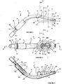
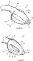
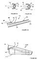
- FIGS 1 to 10 show an artificial airway 2 constructed in accordance with the invention.
- the artificial airway 2 in the illustrated arrangement is assembled from four components: an inflatable cuff 4, airway tube 6, connector body 8 and joining sleeve 10.
- the inflatable cuff 4 is shown in an uninflated position.
- the cuff 4 has a generally wedge shape as seen in side view. It has however an evacuation chamber 12 at its distal end.
- the cuff also has a generally wedge shape when viewed in plan except that it is somewhat truncated at its distal end where the evacuation chamber 12 is located.
- the cuff includes a recess 14 which communicates with conduits in the airway tube 6 to permit an anaesthetic gas or air to be administered to the lungs of a patient, as will be described in more detail below.
- the cross-sectional view of Figure 6 shows the cross-sectional configuration of the airway tube 6. It will be seen that it is generally D-shaped in cross-section having a curved posterior side 16 and generally flat anterior side 18.
- the airway tube 6 includes two airway conduits 20 and 22 which convey anaesthetic gas or air to the recess 14, as will be described in more detail below.
- the airway tube 6 includes an inflation conduit 24 which is in fluid communication with the interior of the cuff 4 to enable inflation thereof.
- the airway tube 6 further includes an evacuation conduit 26, the distal end of which is in fluid communication with the interior of the evacuation chamber 12.
- the airway tube 6 further includes an evacuation chamber vent conduit 28 which also opens to the interior of the evacuation chamber 12.
- the cuff includes a proximal connecting spigot 30 which is of complementary shape to the airway tube 6.
- the spigot 30 is bonded to the outer surface of the airway tube by means of silicon adhesive so as to form a gas-tight seal therewith.
- the posterior wall 31 of the cuff 4 is a generally semi-cylindrical portion 32 which is contiguous with the adjacent part of the spigot 30, as best seen in Figure 1 .
- the portion 32 accommodates the distal end portion 34 of the tube 6 which enters the cuff 4 as best seen in Figure 5 .
- the distal end of the cuff is formed with a distal spigot 36 which is bonded to the adjacent part of the airway tube 6.
- the interior of the spigot 36 defines the evacuation chamber 12.
- the airway tube 6 is formed with two longitudinally extending airway openings 40 and 42 which communicate with the airway conduits 20 and 22 respectively so as to permit anaesthetic gas to pass into the recess 14. It will be appreciated from Figure 7 that the conduits 24, 26 and 28 are not in fluid communication with the recess 14.
- the posterior wall 31 of the cuff includes two laterally extending lobes 44 and 46 which extend laterally from the semi-cylindrical portion 32 and generally extend from the proximal spigot 30 and the distal spigot 36.
- the cuff includes lateral sidewalls 48 and 50 which extend downwardly from the lobes 44 and 46 and merge into an anterior sealing wall 52.
- the anterior sealing wall 52 is generally flat, that is to say lies within a single plane.
- the cuff includes a proximal end wall 51, the edges of which merge into the lateral sidewalls 48 and 50 and the sealing wall 52 In use the anterior sealing wall 52 seals about the epiglottic opening of a patient, as will be described in more detail below.
- the cuff includes lateral inner sidewalls 53 and 54 which merge upwardly from the anterior sealing wall 52 to define the lateral parts of the recess 14.
- the cuff also includes proximal and distal inner sidewalls 55 and 57 which also merge upwardly from anterior sidewall 52 to define the end parts of the recess 14.
- the upper periphery of the inner sidewalls 53, 54, 55 and 57 are formed with a rim 56 which includes a rebate 58 at its inner edge.
- the rebate 58 is shaped so as to be complementary to the anterior edge of the airway tube 6 adjacent to the openings 40 and 42. Silicon bonding agent is used to bond the rim 56 to the adjacent edges of the airway tube 6 so that the entire upper periphery of the inner sidewalls 54 is bonded so as to form a gas-tight seal therewith.
- the cuff is joined to the end portion 34 of the airway 6 only at the spigots 30 and 34 and the upper periphery of the sidewalls 54 as described above.
- the end portion 34 of the airway tube 6 includes a notch 60 which communicates with the inflation conduit 24 so as to permit the cuff 4 to be inflated.
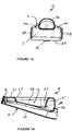
- Figures 11 to 13 show the cuff 4 prior to bonding to the end potion 34 of the airway tube 6.
- the cuff is preferably injection moulded from silicon rubber having a Shore A hardness in the range 25 to 40.
- the wall thickness is preferably in the range from 1 to 2 mm. In the illustrated embodiment, the wall thickness is uniform and is approximately 1 mm in thickness. Alternatively, the wall thickness could be varied in order to produce differential expansions when inflated and in this case the wall thickness would be about 1 mm in thickness at the thinner parts and about 2 mm at the wider parts.
- the wall thickness could be thicker in the walls which define the anterior sealing wall 52 and the inner sidewalls 53, 54, 55 and 57 and proximal end wall 51 so that these walls tend to maintain their shape during inflation.
- the lateral sidewalls 48, 50 and the posterior wall 31 are preferably thinner so that these walls expand to a greater extent during inflation.
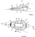
- the cuff is generally wedge-shaped when viewed from the side, as shown in Figure 11 .
- the apex angle A is preferably 15° to 25° and preferably 20°.
- the cuff is also generally wedge-shaped when viewed in plan, as seen in Figure 12 , except that the apex is truncated, where the spigot 36 is located.
- the apex angle B is preferably in the range from 20° to 30° and most preferably about 22.5°. It will also be seen that the sidewalls 48 and 50 when viewed in plan are relatively straight or have only a very slight curve.
- the recess 14 is of a rectangular shape when viewed in plan as seen in Figure 12 . Further, the inner sidewalls 53, 54, 55 and 57 are inclined inwardly towards to the rim 56 at an angle of about 15°.
- the length of the cuff 4 as measured in the longitudinal direction is approximately 93 mm and the widest portion, that is to say between the lateral sidewalls 46 and 48, is about 50 mm.
- the height of the sidewall 48 varies from about 8 mm at the distal end of the cuff to about 20 mm at the proximal end.
- the distance from the anterior sealing wall 52 to the highest point on the cylindrical portion 32 is about 34 mm adjacent to the spigot 30 and decreases to about 12 mm adjacent to the distal spigot 36.
- these dimensions can be varied in accordance with the size of the airway tube being made.
- the aforementioned dimensions refer to the uninflated cuff.
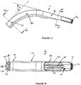
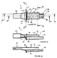
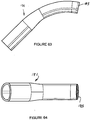
- Figures 15 to 24 show the preferred shape of the airway tube 6.
- the airway tube 6 is preferably injection moulded from silicon rubber having a Shore A hardness of 35 and preferably within the range from 35 to 50. It will be seen from Figure 17 that the end portion 34 forms an angle C with the proximal end portion 70, there being a curved intermediate portion 72 therebetween. Preferably angle C is in the range 50° to 75° and most preferably about 60°. It is preferred that the airway tube 6 is initially injection moulded in a straight condition and then heated in a former so as to form the curved portion 72.
- the conduits 20, 22, 24, 26 and 28 can all be formed during the moulding process.
- the openings 40 and 42 can also be formed in the moulding process.
- a central longitudinally-extending ridge 74 is formed between the openings 40 and 42.
- the ridge 74 imparts additional rigidity to the end portion 34 of the airway tube 6. It further serves to prevent the epiglottis of the patient obstructing the openings 40 and 42.
- the distal end of the end portion 34 tapers somewhat so as to better conform to the interior shape of the cuff 4.
- the distal end of the end portion 34 is moulded with an integral hollow projection 76 which is of a generally oval shape in cross-section.
- the outer shape of the projection 76 is generally complementary to the shape of the distal spigot 36 and is located therein so as to impart additional rigidity to the shape of the evacuation chamber 12.
- the distal ends of the conduits 26 and 28 open into the interior of the projection 76 so as to provide fluid communication with the chamber 12.
- the notch 60 can also be integrally formed during the moulding process.
- the airway tube 18 could be regarded as being generally uniform in cross-section along its length except that the end part 34 has part of the flat anterior side 18 removed.
- the anterior wall 18 is completely removed in a generally rectangular shape but having rounded corners at the distal and proximal ends, as seen in Figure 18 .
- the edges of the sidewalls 53, 54, 55 and the rim 56 are bonded to the airway tube adjacent to this opening by means of silicone glue. It will be appreciated, however, that from a functional point of view the cuff could be connected to the airway tube in different ways.
- parts corresponding to the sidewalls 53, 54, 55 and 57 could be integrally moulded with the airway tube, although this would make moulding of the tube more difficult. If, however, this modification were made the inner edges of the anterior sealing wall 52 could be bonded to the adjacent lower edges of the sidewalls integrally formed with the airway tube. Other intermediate variations would also be possible. It is preferred, however, to mould the airway tube 6 and the cuff 4 as shown in the drawings.
- the airway tube 6 could be formed in two separate parts.
- the end part 34 could be moulded separately from the parts 70 and 72 which could be formed by extrusion bent into the correct shape and then joined to the end portion 34.
- the length of the airway tube 6 is about 170 mm (when straight) and the transverse width is about 25 mm.
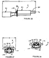
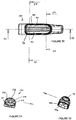
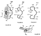
- Figures 26 to 31 illustrate in more detail the connector body 8.
- the connector body is integrally moulded from plastics material such as polycarbonate. It would be possible to mould the body 8 in a number of parts and connect them together by bonding or heat or ultrasonic welding.
- the connector body 8 includes a 15mm male Luer connector 80 formed at the proximal end of the body.
- the body includes an intermediate portion 82 from which project three distal spigots 84, 86 and 88.
- the spigots 84, 86 and 88 have outer diameters such that they can be snugly inserted in the proximal ends of the conduits 28, 26 and 24 respectively so as to establish fluid communication with these conduits.
- the spigots may be slightly tapered to facilitate assembly of the connector body 8 onto the airway tube 6.
- the lengths of the spigots are about 15 mm.
- the intermediate portion 82 includes passages 90, 92 and 94 which communicate with the hollow spigots 84, 86 and 88 respectively.
- the proximal end of the passage 90 is constituted by a port 96 which is formed in a transverse wall 98 and is open to atmosphere. In use air is admitted through the port 96 so that it can pass into the passage 90 and then through the evacuation chamber vent conduit 28 and be admitted to the evacuation chamber 12.
- the intermediate portion 82 is formed with a laterally-projecting hollow spigot 100 which communicates with the passage 92.
- the passage 92 is in fluid communication with the hollow spigot 86 which in turn establishes fluid communication with the evacuation conduit 26.
- a source of suction can be applied via the spigot 100 so as to establish suction within the evacuation chamber 12 to which the distal end of the conduit 26 opens.
- the intermediate portion 82 is also formed with a laterally-projecting hollow spigot 102 which communicates with the passage 94 which is in fluid communication with the hollow spigot 88.
- the hollow spigot 88 is inserted into the inflation conduit 24.
- positive pressure can be applied to the spigot 102 via a syringe in order to pressurise the inflation conduit and thus inflate the cuff 4 to the required degree.
- the anterior side of the intermediate portion 82 is essentially hollow and forms a relatively wide passage 104 which, at the proximal end is in communication with the Luer connector 80 and at the distal end communicates with the ends of the airway conduits 20 and 22.
- the distal end of the intermediate portion 82 is formed as a shoulder 106 which abuts the adjacent end of the airway tube 6 so that the passage 104 communicates with the conduits 20 and 22.
- the should 106 abutting the end of the tube 6 is preferred because, if connecting spigots were used to establish fluid communications with the airway conduits 20 and 22, there would be undesirable constrictions caused by the spigots.
- the direct abutment of the shoulder 106 provides the least amount of obstruction to flow of anaesthetic gases. There is little prospect of leakage between the passage 104 and the other passages at the junction because of the insertion of the spigots 84, 86 and 88 into the corresponding conduits essentially isolates them from the passage 104.
- the overall length of the connecting body 8 is about 101 mm and the maximum width, that is to say as measured between the ends of the spigots 100 and 102, is 40 mm.
- the rigid body 8 mounted on the proximal end of the airway tube 6 provides rigidity at this point of the artificial airway which is sometimes useful for fixing of the position of the artificial airway. This also prevents the airway being damaged or obstructed in the event of the patient biting upon the airway.
- the connecting sleeve 10 provides a soft resilient surface that will prevent damage to the patient's teeth should biting occur.
- the cross-section shape of the periphery of the intermediate portion as shown in Figure 31 corresponds to the cross-sectional shape at the proximal end of the airway tube 6. This enables the connecting sleeve 10 to be snugly mounted over the intermediate portion 82 and the proximal end of the tube 6.
- Figure 33 shows the sleeve 10. It is extruded or moulded from silicon rubber and has a hardness which is similar to that of the airway tube 6.
- the tube 10 has a bore 120 which is of complementary shape to the outer surface of the intermediate portion 82 and the airway tube 6.
- the length of the sleeve 10 is preferably about 60 mm. From a functional point of view it needs to be longer than the length of the intermediate portion 82 as measured from the wall 98 to the shoulder 106 so that the sleeve 10 fully covers the exterior of the intermediate portion 82 and about 20 mm of the proximal end of the airway tube 6.
- the preferred sequence of fabrication of the device is to separately mould the cuff 4, airway tube 6, connector body 8 and sleeve 10.
- the initially straight airway tube 6 is then heat formed into a curved shape as described previously.
- the cuff 4 can then be mounted on the end portion 34 of the airway tube 6 and bonded thereto as described earlier.
- the sleeve 10 can then be slid along the proximal end of the airway tube 6 so that the spigots 84, 86 and 88 can be inserted into their respective conduits. Silicon bonding agent may also be used to fix them in position.
- Silicon bonding agent is then applied to the bore 120 of the sleeve and it is moved in a proximal direction so that is proximal end engages the transverse wall 98. In this way a gas tight join is formed between the connector body 8 and the end of the airway tube 6 with the necessary fluid communication paths established.
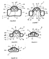
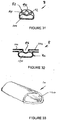
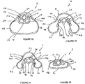
- FIGS 34 to 39 schematically illustrate the cuff in its fully deflated position.
- the cuff can be deflated by connecting a syringe to a lumen (not shown in Figures 34 to 39 ) connected to the spigot 102.
- the cuff 4 is deflated so that it can be more easily inserted through the mouth and throat of the patient.
- the lobes 44 and 46 collapse so as to form laterally-extending wings 130 and 132 which vary in size and shape towards the distal ends of the cuff.
- the anterior surface 52 and the inner sidewalls 54 collapse so as to form anteriorly-extending wings 134 and 136 which again vary in shape and width along the length of the cuff.
- the wings 130, 132, 134 and 136 are somewhat randomly oriented but more importantly they can readily be resiliently deflected during the insertion process.
- Figures 40 to 45 schematically show the shape of the cuff, in its inflated position.
- the cuff 4 is inflated to a pressure within the range 40-60 cm H 2 O pressure.
- the lobes 44 and 46 are somewhat extended laterally. More significantly however the posterior wall 31 is significantly displaced from the posterior wall 16 of the end portion 34 of the airway tube 6, as best seen in Figure 43 .
- the inflated position there are still longitudinal depressions 140 and 142 generally located between the lobes 44 and 46 and the adjacent parts of the posterior wall 31, as seen in Figure 43 .
- the depressions 140 and 142 serve to impart some stability to the inflated structure to intend to resist twisting thereof, after or during inflation.
- the maximum width of the cuff 4 is about 52 mm and the maximum height as measured between the anterior sealing surface 52 and the posterior wall 31 is about 33 mm for a size 4 device and these dimensions will vary with smaller and larger devices as is well known in the art.
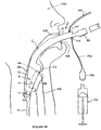
- Figure 46 diagrammatically illustrates the manner in which the artificial airway 2 is deployed in a patient 150.
- the cuff 4 is initially deflated by using a syringe 152 which is connected to the spigot 102 by means of a lumen 154 via a valve 156 which normally closes the lumen 154 except when the syringe 152 is connected thereto.
- the artificial airway 2 can then be inserted through the throat of the patient until the cuff is located adjacent to the glottic opening 158.
- the distal end of the cuff 4 is located adjacent to the upper oesophageal sphincter 160.
- the syringe 152 can then be used to inflate the cuff 4 to the required degree.
- the shape of the cuff as described above generally anatomically conforms to the corresponding anatomical features of the patient whereby an excellent seal is maintained between the anterior wall 52 and the area surrounding the glottic opening 158.
- a prototype of the device has been tested and it has been found that the seal is higher than is available with currently available airway devices.
- the prototype of the invention has been tested at a pressure of 28 to 36 cm of H 2 O whereas most currently available commercial airways typically have a maximum of about 28 cm H 2 O.
- the evacuation chamber 12 is presented to the oesophagus 161 of the patient.
- a source of suction can be connected via a lumen 164 to the spigot 100 in order to cause suction within the chamber 12.
- the chamber 12 is vented to atmosphere by the evacuation chamber vent conduit 28, there is only a limited amount of suction towards the proximal part of the chamber 12. This avoids the undesirable effect of having the chamber 12 sucked directly onto the tissue surfaces of the patient which could cause damage. Any material regurgitated from the oesophagus 161 will enter the chamber 12 and will be entrained into the flow of air which passes from the evacuation chamber vent conduit 28 into the evacuation conduit 26.
- the chamber 120 is vented to atmosphere, there is very little prospect that the chamber could be maintained in a state of suction against the mucosa of the upper oesophageal sphincter or parts adjacent thereto. This avoids the possibility of damage to the tissue of the patient. Also the arrangement has advantages over prior art arrangements in which evacuation tubes can communicate directly with the oesophagus of the patient and apply negative pressure thereto which could have the effect of inducing regurgitation.
- the epiglottis 166 of the patient is normally located adjacent to the recess 14 and the ridge 74 of the airway tube tends to prevent the epiglottis obstructing the airways openings 40 and 42.
- the teeth 168 of the patient are located adjacent to the sleeve 10 which is resilient as it is formed from silicon rubber. This helps to prevent damage to the patient and to the artificial airway.
- FIGS 47 to 64 show details of a modified airway constructed in accordance with the invention.
- the same reference numerals have been used to denote parts which are the same as or correspond to those of the first embodiment.
- the airway tube 6 is made in two components, a distal component 180 which is interconnected with a proximal component 181. These components are joined together by means of bonding or gluing or the like and when connected together correspond in shape to the airway 6.
- the proximal component 181 can be connected to the joining sleeve 10 as in the previous embodiment.
- the distal component 180 includes a rebate 182 which, in use, connects to a complementary rebate 183 formed in the distal end of the proximal component 181, as best shown in Figure 64 .
- the rebates 182 and 183 facilitate alignment and gluing or bonding thereto.
- the component 180 includes a projecting wall 184 which projects somewhat from the anterior side of the component 180.
- the interior of the wall 184 defines an elongate oval shaped recess 186 which corresponds to the recess 14 of the cuff.
- the anterior edge of the wall 184 is formed with a groove 188 and shoulder 190 outwardly adjacent thereto.
- the component 180 includes a rebate 192 surrounding the vent conduit 28 at its distal end, as best seen in Figures 47 and 53 .
- proximal and distal components 181 and 180 are each easier to mould than a single component and this therefore reduces the overall cost of the device.
- Figures 57 to 61 illustrate a modified form of cuff 200 which is shaped so as to facilitate mounting onto the component 180.
- the cuff 200 differs in two significant ways from that shown in the previous embodiment.
- the first difference is that the inner sidewalls 53, 54, 55 and 57 are formed with a lip 202 which projects generally inwardly relative to the recess 14.
- the lip 202 is shaped so as to be received within the groove 188 of the component 180 and adjacent to the shoulder 190. This facilitates bonding and or gluing of the cuff to the component 180. This is best seen in the enlarged schematic view of Figure 62 .
- the second major change that the cuff 200 has relative to the cuff 4 of the previous embodiment is that the distal spigot 36 is formed with an inwardly directed integral flange 204, as best shown in Figure 59 .
- the flange 204 is, in use, located within the rebate 192 formed at the distal end of the component 180.
- the provision of the flange 204 therefore defines a smooth entrance to the evacuation chamber 12.
- any excess glue or bonding agent, if present, will be located inwardly of the proximal end of the airway so that there should not be any rough or sharp edges at the distal end caused by such excess glue or bonding agent.
- the appearance of the cuff is also enhanced because it has a smooth entrance to the evacuation chamber 12.
- the proximal connecting spigot 30 of the cuff is sufficiently long that it covers the join line between the component 180 and the remainder of the airway tube. This helps to prevent any gas leakages and also gives a neat appearance to the airway. Further, any excess glue or bonding agent used to interconnect the component 180 with the remainder of the airway would be covered by the spigot 30 and therefore avoid any unwanted projections on the exterior of the airway caused by such excess glue or bonding agent.
- the device of the invention is moulded from relatively few components which are inexpensive to make. Further, the assembly process is comparatively simple compared with the assembly needed for known artificial airways.
- the shape of the cuff of the invention is wedge shaped, as described above, when viewed in side view and plan. This provides better conformity with the anatomical shape of a patient when the cuff is inflated compared with the elliptical or oval toroidal or annular rings of most prior art devices.
- the device of invention is thus inexpensive enough that it can be made as a single use or disposable device but it could be auto-clavable for multiple use.
Landscapes
- Health & Medical Sciences (AREA)
- Pulmonology (AREA)
- General Health & Medical Sciences (AREA)
- Life Sciences & Earth Sciences (AREA)
- Anesthesiology (AREA)
- Biomedical Technology (AREA)
- Heart & Thoracic Surgery (AREA)
- Hematology (AREA)
- Engineering & Computer Science (AREA)
- Animal Behavior & Ethology (AREA)
- Emergency Medicine (AREA)
- Public Health (AREA)
- Veterinary Medicine (AREA)
- Business, Economics & Management (AREA)
- Emergency Management (AREA)
- Prostheses (AREA)
Priority Applications (2)
| Application Number | Priority Date | Filing Date | Title |
|---|---|---|---|
| EP18195495.9A EP3434307B1 (en) | 2009-07-06 | 2010-07-06 | Artificial airway |
| DE10796578.2T DE10796578T1 (de) | 2009-07-06 | 2010-07-06 | Künstlicher atemweg |
Applications Claiming Priority (2)
| Application Number | Priority Date | Filing Date | Title |
|---|---|---|---|
| AU2009903153A AU2009903153A0 (en) | 2009-07-06 | Artificial Airway | |
| PCT/AU2010/000861 WO2011003135A1 (en) | 2009-07-06 | 2010-07-06 | Artificial airway |
Related Child Applications (2)
| Application Number | Title | Priority Date | Filing Date |
|---|---|---|---|
| EP18195495.9A Division-Into EP3434307B1 (en) | 2009-07-06 | 2010-07-06 | Artificial airway |
| EP18195495.9A Division EP3434307B1 (en) | 2009-07-06 | 2010-07-06 | Artificial airway |
Publications (3)
| Publication Number | Publication Date |
|---|---|
| EP2451516A1 EP2451516A1 (en) | 2012-05-16 |
| EP2451516A4 EP2451516A4 (en) | 2016-12-28 |
| EP2451516B1 true EP2451516B1 (en) | 2018-12-19 |
Family
ID=43428663
Family Applications (2)
| Application Number | Title | Priority Date | Filing Date |
|---|---|---|---|
| EP18195495.9A Active EP3434307B1 (en) | 2009-07-06 | 2010-07-06 | Artificial airway |
| EP10796578.2A Revoked EP2451516B1 (en) | 2009-07-06 | 2010-07-06 | Artificial airway |
Family Applications Before (1)
| Application Number | Title | Priority Date | Filing Date |
|---|---|---|---|
| EP18195495.9A Active EP3434307B1 (en) | 2009-07-06 | 2010-07-06 | Artificial airway |
Country Status (12)
| Country | Link |
|---|---|
| US (2) | US9265904B2 (ja) |
| EP (2) | EP3434307B1 (ja) |
| JP (3) | JP5938773B2 (ja) |
| KR (1) | KR20120070559A (ja) |
| CN (2) | CN105268073A (ja) |
| AU (3) | AU2010269117B2 (ja) |
| CA (1) | CA2766690C (ja) |
| DE (2) | DE10796578T1 (ja) |
| MY (2) | MY175111A (ja) |
| NZ (1) | NZ597652A (ja) |
| WO (1) | WO2011003135A1 (ja) |
| ZA (1) | ZA201200333B (ja) |
Families Citing this family (31)
| Publication number | Priority date | Publication date | Assignee | Title |
|---|---|---|---|---|
| GB0903654D0 (en) | 2009-03-03 | 2009-04-15 | Laryngeal Mask Company The Ltd | Artificial airway device |
| AU2010269117B2 (en) | 2009-07-06 | 2014-07-10 | Teleflex Life Sciences Llc | Artificial airway |
| WO2011017756A1 (en) | 2009-08-13 | 2011-02-17 | Ultimate Medical Pty. Ltd. | Pressure indicator |
| GB201016562D0 (en) | 2010-10-01 | 2010-11-17 | Laryngeal Mask Company The Ltd | Artificial airway device |
| CN103221087B (zh) | 2010-10-15 | 2016-08-03 | 喉罩有限公司 | 人工气道装置 |
| ES2645024T3 (es) * | 2011-02-02 | 2017-12-01 | Umedaes Limited | Vía respiratoria artificial mejorada |
| FR2971945B1 (fr) * | 2011-02-25 | 2014-05-09 | Pascal Lucchina | Routeur bucco-pharyngal |
| US20130125898A1 (en) * | 2011-11-21 | 2013-05-23 | Michael Moonsup Song | Hybrid tubing supraglottic airway device |
| GB201120628D0 (en) | 2011-11-30 | 2012-01-11 | Laryngeal Mask Company The Ltd | Endoscopy device |
| CH706616A2 (de) * | 2012-06-04 | 2013-12-13 | Deltona Innovations Ag | Larynxmaske mit einem supraglottischen Tubus. |
| CN102908704A (zh) * | 2012-10-31 | 2013-02-06 | 南昌贝欧特医疗设备有限公司 | 喉罩 |
| US20140182595A1 (en) * | 2012-12-28 | 2014-07-03 | Covidien Lp | Tracheostomy Tube with Cannula Connector |
| US10188815B2 (en) * | 2013-03-06 | 2019-01-29 | Medcom Flow S.A. | Laryngeal mask with retractable rigid tab and means for ventilation and intubation |
| KR101508131B1 (ko) * | 2013-09-26 | 2015-04-07 | 정민호 | 기도 유지장치 |
| SG2014011720A (en) | 2014-02-10 | 2015-09-29 | Craig Wight Ronald | An airway management device and method of manufacture |
| EP3116574B1 (en) * | 2014-03-12 | 2020-02-12 | Kanag Baska | Improved laryngeal mask |
| US9463296B2 (en) | 2014-04-01 | 2016-10-11 | Michael S. Stix | Laryngeal mask with piriform-fossa conduit |
| US20150352304A1 (en) * | 2015-03-11 | 2015-12-10 | Gemguardian, LLC | Bite Proof Endotracheal Tube |
| AU2016238177B2 (en) | 2015-03-26 | 2021-02-18 | Covidien Lp | Improved acoustical guidance and monitoring system |
| US20180177964A1 (en) * | 2016-12-22 | 2018-06-28 | Tianjin Medan Medical Corp. | Glottis mask airway |
| JP6807080B2 (ja) * | 2017-01-31 | 2021-01-06 | 欣也 藤田 | 内視鏡装置 |
| GB201718647D0 (en) * | 2017-11-10 | 2017-12-27 | Teleflex Life Sciences Unlimited Co | Medical container |
| CN108671346A (zh) * | 2018-05-24 | 2018-10-19 | 无锡圣诺亚科技有限公司 | 定位吸痰喉罩 |
| GB201810485D0 (en) * | 2018-06-26 | 2018-08-08 | Teleflex Life Sciences Unlimited Co | Connector |
| GB2576021B (en) * | 2018-08-01 | 2022-05-11 | Blue Bean Medical Ltd | An airway device |
| JP2022508137A (ja) * | 2018-11-20 | 2022-01-19 | グレン・ピー・ガードナー | 挿管用/肺換気用の二機能声門上エアウェイ |
| CN109621128A (zh) * | 2019-01-18 | 2019-04-16 | 浙江简成医疗科技有限公司 | 一种可扩张的内窥镜诊疗用喉罩 |
| EP3698836A1 (en) * | 2019-02-25 | 2020-08-26 | Visual Oxy, S.L. | Laryngeal mask |
| AU2019461089A1 (en) * | 2019-08-09 | 2022-03-03 | Ony Biotech Inc. | Medicament delivery device |
| US11364357B1 (en) * | 2021-09-10 | 2022-06-21 | Casey D. Barton | Pharyngeal respirators |
| KR102652251B1 (ko) * | 2021-10-06 | 2024-03-27 | 연세대학교 산학협력단 | 형상유지부재가 삽입배치된 후두마스크 |
Citations (10)
| Publication number | Priority date | Publication date | Assignee | Title |
|---|---|---|---|---|
| EP0389272A2 (en) | 1989-03-22 | 1990-09-26 | Archibald Ian Jeremy Dr. Brain | Artifical airway device |
| US5241956A (en) | 1992-05-21 | 1993-09-07 | Brain Archibald Ian Jeremy | Laryngeal mask airway with concentric drainage of oesophagus discharge |
| WO1997012640A1 (en) | 1995-10-03 | 1997-04-10 | Archibald Ian Jeremy Brain | Artificial airway device |
| US5865176A (en) | 1995-03-08 | 1999-02-02 | Michael Jeffrey O'Neil | Artificial airway device with sealing cuff for distal end |
| US5937860A (en) | 1997-04-10 | 1999-08-17 | Cook; Daniel J. | Laryngeal mask |
| WO2000009189A1 (en) | 1998-08-13 | 2000-02-24 | Archibald Ian Jeremy Brain | Laryngeal mask airway device |
| US20040089307A1 (en) | 1999-10-07 | 2004-05-13 | Brain Archibald I. J. | Laryngeal mask with large-bore gastric drainage |
| WO2006125986A1 (en) | 2005-05-27 | 2006-11-30 | The Laryngeal Mask Company Limited | Laryngeal mask airway device |
| CN2882657Y (zh) | 2006-02-27 | 2007-03-28 | 天津市塑料研究所 | 双通道塑料喉罩 |
| WO2010100419A1 (en) | 2009-03-03 | 2010-09-10 | The Laryngeal Mask Company Limited | Artificial airway device |
Family Cites Families (245)
| Publication number | Priority date | Publication date | Assignee | Title |
|---|---|---|---|---|
| US3124959A (en) | 1964-03-17 | Primary differential pressure sensing | ||
| US2096831A (en) | 1936-05-28 | 1937-10-26 | Wappler Frederick Charles | Sterilizable pressure gauge |
| US2099127A (en) | 1936-12-30 | 1937-11-16 | Foregger Co Inc | Pharyngeal bulb gasway |
| US2252874A (en) | 1938-11-04 | 1941-08-19 | Vischer Products Company | Pressure indicator |
| US2839788A (en) | 1953-04-24 | 1958-06-24 | Dembiak Matthew | Method of making hollow plastic or rubber articles |
| US2862498A (en) | 1957-06-14 | 1958-12-02 | Don J Weekes | Endotracheal tube |
| US3529596A (en) | 1968-04-03 | 1970-09-22 | Charles G Garner | Automatic intermittent tracheotomy tube cuff inflator-deflator |
| US3554673A (en) | 1969-01-31 | 1971-01-12 | Sage Instr Inc | Syringe pump |
| US3683908A (en) | 1969-10-20 | 1972-08-15 | Tantrimudalige Anthony Don Mic | Apparatus for sealing the oesophagus and providing artificial respiration |
| US3794036A (en) | 1972-08-02 | 1974-02-26 | R Carroll | Pressure regulated inflatable cuff for an endotracheal or tracheostomy tube |
| US4104357A (en) | 1973-01-10 | 1978-08-01 | Monster Molding, Inc. | Method of rotational molding about plural axes at low rotational speeds |
| US3931822A (en) | 1974-02-26 | 1976-01-13 | Marici Frank N | Automatic alternating cuff endo tracheal tube inflator |
| FR2298147A1 (fr) | 1975-01-17 | 1976-08-13 | Ucc Union Chimique Cont | Appareil donnant l'alarme en cas de debranchement d'un tuyau, en particulier d'un respirateur |
| US4056104A (en) | 1976-01-15 | 1977-11-01 | Burton Jaffe | Endotracheal tube |
| DE2609882C3 (de) | 1976-03-10 | 1982-12-16 | Hauser Verwaltungs-Gesellschaft Mbh, 6370 Oberursel | Feindruckmeßgerät für besonders kleine Meßbereiche |
| US4116201A (en) | 1976-12-20 | 1978-09-26 | The Kendall Company | Catheter with inflation control device |
| US4134407A (en) | 1977-03-25 | 1979-01-16 | Elam James O | External pressure-volume monitor for endotracheal cuff |
| US4159722A (en) | 1977-03-28 | 1979-07-03 | Sherwood Medical Industries, Inc. | Pressure regulator for endotracheal tube cuff or the like |
| US4178938A (en) | 1977-06-24 | 1979-12-18 | Au Anthony S | Pressure control systems |
| US4178940A (en) | 1977-06-24 | 1979-12-18 | Au Anthony S | Pressure control systems |
| GB1529190A (en) | 1977-09-06 | 1978-10-18 | Jaffe B | Endotracheal tube |
| US4351330A (en) | 1978-01-30 | 1982-09-28 | Scarberry Eugene N | Emergency internal defibrillation |
| US4231365A (en) | 1978-01-30 | 1980-11-04 | Scarberry Eugene N | Emergency resuscitation apparatus |
| US4285340A (en) | 1979-03-16 | 1981-08-25 | Gezari Walter A | Apparatus for controlling the pressure in a tracheal cuff |
| US4256099A (en) | 1979-03-21 | 1981-03-17 | Dryden Gale E | Two-tube resuscitation system |
| JPS5667383A (en) | 1979-11-08 | 1981-06-06 | Mitsui Petrochem Ind Ltd | Thixotropic agent |
| DE2945662A1 (de) | 1979-11-12 | 1981-05-21 | Hauser Verwaltungs-Gesellschaft Mbh, 6370 Oberursel | Instrument mit beleuchteter skalenscheibe fuer die analoganzeige von messwerten |
| US4446864A (en) | 1980-07-10 | 1984-05-08 | Watson Robert L | Emergency ventilation tube |
| GB2111394B (en) | 1981-12-16 | 1985-09-11 | Archibald Ian Jeremy Brain | Artificial airway device |
| US4445366A (en) | 1982-06-01 | 1984-05-01 | Carrier Corporation | Pressure differential gage and a method for detecting the presence of noncondensible gases in a refrigeration system |
| US4471775A (en) | 1982-09-07 | 1984-09-18 | Clair Michael W | Endotracheal tube cuff synchronizing system |
| US4501273A (en) | 1982-09-30 | 1985-02-26 | Mcginnis Gerald E | Endotracheal tube with pressure controlled inflatable cuff |
| US4526196A (en) | 1983-01-26 | 1985-07-02 | Nayan S. Shah | Gas pressure measuring and regulating device and method |
| US4583917A (en) | 1983-06-17 | 1986-04-22 | Shah Nayan S | Pressure regulating and monitoring device |
| DE3327342A1 (de) | 1983-07-29 | 1985-02-07 | Peter 7800 Freiburg Pedersen | Vorrichtung zur erfassung und auswertung des druckes in der ballonmanschette eines geschlossenen trachealtubus |
| US4553540A (en) | 1983-08-16 | 1985-11-19 | Straith Richard E | Airway |
| US4689041A (en) | 1984-01-20 | 1987-08-25 | Eliot Corday | Retrograde delivery of pharmacologic and diagnostic agents via venous circulation |
| JPS628766A (ja) | 1985-07-03 | 1987-01-16 | 鳥取大学長 | カフ付気管插入チュ−ブのカフ圧調整装置 |
| US4793327A (en) | 1986-01-21 | 1988-12-27 | Frankel Alfred R | Device for opening a patient's airway during automatic intubation of the trachea |
| JPS62186872A (ja) | 1986-02-14 | 1987-08-15 | 鳥取大学長 | 呼吸圧重畳式カフ圧調整装置 |
| US4700700A (en) | 1986-09-15 | 1987-10-20 | The Cleveland Clinic Foundation | Endotracheal tube |
| US5042469A (en) | 1987-03-24 | 1991-08-27 | Augustine Medical, Inc. | Tracheal intubation guide |
| US4832020A (en) | 1987-03-24 | 1989-05-23 | Augustine Scott D | Tracheal intubation guide |
| US5203320A (en) | 1987-03-24 | 1993-04-20 | Augustine Medical, Inc. | Tracheal intubation guide |
| US4798597A (en) | 1987-04-29 | 1989-01-17 | Sherwood Medical Co | Flexible composite intubation tube |
| GB2205499B (en) | 1987-06-05 | 1991-01-16 | Archibald Ian Jeremy Brain | Artificial airway device |
| US4924862A (en) | 1987-08-19 | 1990-05-15 | Gary Levinson | Pressure controller and leak detector for tracheal tube cuff |
| US4850349A (en) | 1987-12-04 | 1989-07-25 | Farahany Amir H | Endotracheal tube sealing cuff system |
| US4872483A (en) | 1987-12-31 | 1989-10-10 | International Medical Products, Inc. | Conveniently hand held self-contained electronic manometer and pressure modulating device |
| US4856510A (en) | 1988-04-06 | 1989-08-15 | Kowalewski Ryszard J | Tracheal tube inflator |
| US5067496A (en) | 1988-04-07 | 1991-11-26 | Shiley Incorporated | Tracheostomy tube |
| US4972963A (en) | 1988-10-31 | 1990-11-27 | Guarriello Henry J | Blow molded article with reverse lip |
| US4953547A (en) | 1989-01-26 | 1990-09-04 | Poole Jr Samuel E | Drug administering endotracheal respiration systems |
| US5241656A (en) | 1989-02-06 | 1993-08-31 | International Business Machines Corporation | Depth buffer clipping for window management |
| US5060647A (en) | 1989-02-23 | 1991-10-29 | Alessi David M | Endotrachael tube |
| US5169379A (en) | 1989-06-14 | 1992-12-08 | L-Vad Technology | In-series ventricular assist system and method of controlling same |
| US4981470A (en) | 1989-06-21 | 1991-01-01 | Synectics Medical, Inc. | Intraesophageal catheter with pH sensor |
| JPH0339169A (ja) | 1989-07-06 | 1991-02-20 | B Hazaado Patrick | 経皮気管切開チューブ |
| US5042476A (en) | 1989-08-10 | 1991-08-27 | Smith Charles A | Endotracheal tube protection arrangement |
| WO1991003207A1 (en) | 1989-09-08 | 1991-03-21 | Boston Scientific Corporation | Physiologic low stress angioplasty |
| US5038766A (en) | 1989-11-08 | 1991-08-13 | Parker Jeffrey D | Blind orolaryngeal and oroesophageal guiding and aiming device |
| US5174283A (en) | 1989-11-08 | 1992-12-29 | Parker Jeffrey D | Blind orolaryngeal and oroesophageal guiding and aiming device |
| GB9003857D0 (en) | 1990-02-21 | 1990-04-18 | Smiths Industries Plc | Medico-surgical tube assemblies |
| US5237988A (en) | 1990-11-13 | 1993-08-24 | Mcneese Wesley G | Device for fastening an endotracheal tube |
| GB9026403D0 (en) | 1990-12-05 | 1991-01-23 | Smiths Industries Plc | Pressure monitors |
| GB9102821D0 (en) | 1991-02-11 | 1991-03-27 | Brain Archibald Ian Jeremy | An intubating laryngeal mask airway |
| US5339808A (en) | 1991-04-02 | 1994-08-23 | Don Michael T Anthony | Endotracheal-esophageal intubation devices |
| US5235973A (en) | 1991-05-15 | 1993-08-17 | Gary Levinson | Tracheal tube cuff inflation control and monitoring system |
| US5795325A (en) | 1991-07-16 | 1998-08-18 | Heartport, Inc. | Methods and apparatus for anchoring an occluding member |
| GB9119703D0 (en) | 1991-09-14 | 1991-10-30 | Dingley John | Medico-surgical device |
| US5113875A (en) | 1991-09-24 | 1992-05-19 | Bennett Trevor S | Inflatable leg-supporting bolster |
| US5241325A (en) | 1991-10-31 | 1993-08-31 | Hewlett-Packard Company | Print cartridge cam actuator linkage |
| GB9204754D0 (en) | 1992-03-05 | 1992-04-15 | Brain Archibald Ian Jeremy | Mould for manufacture of a laryngeal mask |
| MX9301163A (es) | 1992-03-05 | 1994-07-29 | Brain Archibald Ian Jeremy | Mascara laringea y metodo para su fabricacion. |
| US5273537A (en) | 1992-03-06 | 1993-12-28 | Scimed Life Systems, Inc. | Power-assisted inflation apparatus |
| ES2147753T3 (es) | 1992-03-10 | 2000-10-01 | Univ Duke | Tubo endotraqueal con dispositivo para la generacion de aerosol. |
| US5421325A (en) | 1992-04-30 | 1995-06-06 | Cinberg; James Z. | Endotracheal tube assembly and related method |
| US5546936A (en) | 1992-05-19 | 1996-08-20 | Mallinckrodt Medical, Inc. | Tracheal tube with reinforced flexible segment |
| US5249571A (en) | 1992-05-21 | 1993-10-05 | Brain Archibald Ian Jeremy | Laryngeal clamp airway |
| DE4222220A1 (de) | 1992-07-07 | 1994-01-13 | Deutsche Aerospace | Verfahren zur Messung und Regelung des Druckes in der Dichtmanschette eines Trachealtubus |
| EP0580385B1 (en) | 1992-07-21 | 1996-05-08 | Archibald Ian Jeremy Dr. Brain | Laryngeal mask incorporating a reflectance oximeter |
| GB9215455D0 (en) | 1992-07-21 | 1992-09-02 | Brain Archibald Ian Jeremy | A laryngeal mask airway adapted to carry a reflecting-type oximeter |
| US5297547A (en) | 1992-07-30 | 1994-03-29 | Brain Archibald Ian Jeremy | Laryngeal mask construction |
| ZA927931B (en) | 1992-08-24 | 1994-04-14 | Donald Munro Miller | Breathing apparatus |
| US5355879A (en) | 1992-09-28 | 1994-10-18 | Brain Archibald Ian Jeremy | Laryngeal-mask construction |
| US5400771A (en) | 1993-01-21 | 1995-03-28 | Pirak; Leon | Endotracheal intubation assembly and related method |
| US5331967A (en) | 1993-02-05 | 1994-07-26 | Playa De Los Vivos S.A. | Tracheal intubation monitoring apparatus and method |
| US5546935A (en) | 1993-03-09 | 1996-08-20 | Medamicus, Inc. | Endotracheal tube mounted pressure transducer |
| GB9312131D0 (en) | 1993-06-11 | 1993-07-28 | Blatchford & Sons Ltd | Prosthesis control system |
| FR2709251B1 (fr) | 1993-08-26 | 1995-11-10 | Georges Boussignac | Tube d'assistance respiratoire. |
| US5443063A (en) | 1993-08-31 | 1995-08-22 | The Johns Hopkins University | Cuffed oro-pharyngeal airway |
| US6062219A (en) | 1993-11-09 | 2000-05-16 | Cprx Llc | Apparatus and methods for assisting cardiopulmonary resuscitation |
| US5692498A (en) | 1993-11-09 | 1997-12-02 | Cprx, Inc. | CPR device having valve for increasing the duration and magnitude of negative intrathoracic pressures |
| US5551420A (en) | 1993-11-09 | 1996-09-03 | Cprx, Inc. | CPR device and method with structure for increasing the duration and magnitude of negative intrathoracic pressures |
| US5599301A (en) | 1993-11-22 | 1997-02-04 | Advanced Cardiovascular Systems, Inc. | Motor control system for an automatic catheter inflation system |
| US5459700A (en) | 1993-11-22 | 1995-10-17 | Advanced Cardiovascular Systems, Inc. | Manual timer control for inflation device |
| US5554673A (en) | 1993-11-29 | 1996-09-10 | Polygenex International, Inc. | Dip molded polyurethane film compositions |
| GB2285765B (en) | 1994-01-12 | 1997-10-29 | Archibald Ian Jeremy Brain | Forming tool for use with a laryngeal mask |
| US5499625A (en) | 1994-01-27 | 1996-03-19 | The Kendall Company | Esophageal-tracheal double lumen airway |
| US5529582A (en) | 1994-02-01 | 1996-06-25 | Fukuhara; Tomio | Apparatus for inserting laryngeal mask |
| US5582167A (en) | 1994-03-02 | 1996-12-10 | Thomas Jefferson University | Methods and apparatus for reducing tracheal infection using subglottic irrigation, drainage and servoregulation of endotracheal tube cuff pressure |
| JP3782123B2 (ja) | 1994-05-31 | 2006-06-07 | 住友ベークライト株式会社 | 咽腔用エアウエイ |
| GB9411215D0 (en) | 1994-06-04 | 1994-07-27 | Brain Archibald Ian Jeremy | A fibreoptic intubating laryngeal mask airway |
| JPH08547A (ja) | 1994-06-23 | 1996-01-09 | Koushinshiya:Kk | 内視鏡挿入ガイド |
| SE503155C2 (sv) | 1994-07-28 | 1996-04-01 | Comasec International Sa | Sätt och anordning för funktionskontroll vid andningsapparat |
| US5569219A (en) | 1994-09-13 | 1996-10-29 | Hakki; A-Hamid | Collapsible catheter |
| GB9422224D0 (en) | 1994-11-03 | 1994-12-21 | Brain Archibald Ian Jeremy | A laryngeal mask airway device modified to detect and/or stimulate mescle or nerve activity |
| DE4447186A1 (de) | 1994-12-30 | 1996-07-11 | Johann Dr Med Wittenbeck | Larynxmaske (=Kehlkopfmaske) zur fiberoptischen endotrachealen Intubation bei gleichzeitiger künstlicher Beatmung eines Patienten |
| US5577693A (en) | 1995-01-11 | 1996-11-26 | Children's Medical Center Corporation | Anesthesia circuit stand |
| US5477851A (en) | 1995-01-26 | 1995-12-26 | Callaghan; Eric B. | Laryngeal mask assembly and method for removing same |
| GB9505134D0 (en) | 1995-03-14 | 1995-05-03 | Smiths Industries Plc | Laryngeal mask airways |
| GB2298797B (en) | 1995-03-14 | 1998-12-09 | Smiths Industries Plc | Laryngeal mask airways |
| GB9505399D0 (en) | 1995-03-17 | 1995-05-03 | Smiths Industries Plc | Medico-surgical devices |
| GB9513860D0 (en) | 1995-07-07 | 1995-09-06 | Smiths Industries Plc | Securing devices |
| AUPN417395A0 (en) | 1995-07-14 | 1995-08-10 | Techbase Pty. Ltd. | An improved spacer |
| AUPN538495A0 (en) | 1995-09-12 | 1995-10-05 | Esnouf, Philip Stuart | Disposable oxygenating device |
| MY115052A (en) | 1995-10-03 | 2003-03-31 | Archibald Ian Jeremy Brain | Laryngeal mask airway incorporating an epiglottic elevating mechanism |
| US5794617A (en) | 1995-10-19 | 1998-08-18 | Louis M. Gerson Co., Inc. | Face mask and retainer |
| US5791341A (en) | 1995-12-19 | 1998-08-11 | Bullard; James Roger | Oropharyngeal stent with laryngeal aditus shield and nasal airway with laryngeal aditus shield |
| US5832916A (en) | 1996-02-20 | 1998-11-10 | Interspiro Ab | Method and system for checking the operability of electrical-based components in a breathing equipment |
| US20050139220A1 (en) | 1996-02-26 | 2005-06-30 | Evergreen Medical Incorporated | Method and apparatus for ventilation / oxygenation during guided insertion of an endotracheal tube |
| US5694929A (en) | 1996-02-26 | 1997-12-09 | Christopher; Kent L. | Method and apparatus for ventilation/oxygenation during guided insertion of an endotracheal tube |
| US5878745A (en) | 1996-03-01 | 1999-03-09 | Brain; Archibald I.J. | Gastro-laryngeal mask |
| US5626151A (en) | 1996-03-07 | 1997-05-06 | The United States Of America As Represented By The Secretary Of The Army | Transportable life support system |
| GB9606012D0 (en) | 1996-03-22 | 1996-05-22 | Brain Archibald Ian Jeremy | Laryngeal mask with gastric-drainage feature |
| US5623921A (en) | 1996-04-10 | 1997-04-29 | Kinsinger; J. William | Laryngeal mask airway and method for its use |
| US5682880A (en) | 1996-07-26 | 1997-11-04 | Brain; Archibald Ian Jeremy | Laryngeal-mask airway with guide element, stiffener, and fiberoptic access |
| US5738094A (en) | 1996-08-30 | 1998-04-14 | Hoftman; Moshe | Anesthesia/respirator mask with reduced nasal section enclosure and inflatable cuff |
| GB2317342B (en) | 1996-09-18 | 2000-03-29 | Smiths Industries Plc | Laryngeal mask assemblies |
| GB9619432D0 (en) | 1996-09-18 | 1996-10-30 | Smiths Industries Plc | Laryngeal mask assemblies |
| GB9620609D0 (en) | 1996-10-03 | 1996-11-20 | Smiths Industries Plc | Laryngeal mask airways and their manufacture |
| GB2317830B (en) | 1996-10-03 | 2000-03-29 | Smiths Industries Plc | Laryngeal mask airways and their manufacture |
| GB2318297B (en) | 1996-10-16 | 2000-04-12 | Smiths Industries Plc | A tracheal shield assembly |
| US6427686B2 (en) | 1996-10-16 | 2002-08-06 | Augustine Medical, Inc. | Airway device with provision for coupling to an introducer |
| US6070581A (en) | 1996-10-16 | 2000-06-06 | Augustine Medical, Inc. | Laryngeal airway device |
| US7051096B1 (en) | 1999-09-02 | 2006-05-23 | Citicorp Development Center, Inc. | System and method for providing global self-service financial transaction terminals with worldwide web content, centralized management, and local and remote administration |
| GB9622880D0 (en) | 1996-11-02 | 1997-01-08 | Smiths Industries Plc | Laryngeal mask airways and thier manufacture |
| GB2318735B (en) | 1996-11-02 | 2000-04-19 | Smiths Industries Plc | Laryngeal mask airways and their manufacture |
| US6003511A (en) | 1996-11-18 | 1999-12-21 | Medlis Corp. | Respiratory circuit terminal for a unilimb respiratory device |
| US5778872A (en) | 1996-11-18 | 1998-07-14 | Medlis, Inc. | Artificial ventilation system and methods of controlling carbon dioxide rebreathing |
| GB9624029D0 (en) | 1996-11-19 | 1997-01-08 | Smiths Industries Ltd | Laryngeal mask airways and their manufacture |
| GB2319478B (en) | 1996-11-19 | 2000-04-19 | Smiths Industries Plc | Laryngeal mask airways and their manufacture |
| US5856510A (en) | 1996-12-16 | 1999-01-05 | Allelix Biopharmaceuticals Inc. | 5-alkenyl and 5-alkynyl indole compounds |
| JP3503730B2 (ja) | 1996-12-24 | 2004-03-08 | 住友ベークライト株式会社 | 救急蘇生用食道内エアウェイ |
| US5921239A (en) | 1997-01-07 | 1999-07-13 | Sunrise Medical Hhg Inc. | Face mask for patient breathing |
| GB9702337D0 (en) | 1997-02-05 | 1997-03-26 | Smiths Industries Plc | Laryngeal mask airways and their manufacture |
| GB9705537D0 (en) | 1997-03-18 | 1997-05-07 | Smiths Industries Plc | Laryngeal mask assemblies |
| US5743254A (en) | 1997-03-18 | 1998-04-28 | Parker Medical Limited Partnership | Orotracheal intubation guide |
| GB9705585D0 (en) | 1997-03-18 | 1997-05-07 | Smiths Industries Plc | Laryngeal mask assemlies |
| GB2323289B (en) | 1997-03-18 | 2001-02-14 | Smiths Industries Plc | Laryngeal mask assemblies |
| GB9705586D0 (en) | 1997-03-18 | 1997-05-07 | Smiths Industries Plc | Laryngeal mask assemblies |
| US8631796B2 (en) | 1997-04-10 | 2014-01-21 | Cookgas, L.L.C. | Laryngeal mask |
| GB9708568D0 (en) | 1997-04-29 | 1997-06-18 | Smiths Industries Ltd | Cuffed medico-surgical tubes |
| US6131571A (en) | 1997-04-30 | 2000-10-17 | University Of Florida | Ventilation apparatus and anesthesia delivery system |
| US5988167A (en) | 1997-05-02 | 1999-11-23 | Kamen; Jack M. | Foam cuff for laryngeal mask airway |
| GB2324737A (en) | 1997-05-03 | 1998-11-04 | Smiths Industries Plc | Laryngeal mask assembly |
| GB9709297D0 (en) | 1997-05-03 | 1997-06-25 | Smiths Industries Plc | Laryngeal mask assemblies |
| GB9710645D0 (en) | 1997-05-22 | 1997-07-16 | Smiths Industries Plc | Cuffed tube assemblies |
| JPH10323391A (ja) | 1997-05-23 | 1998-12-08 | Aoki Shigeru | 安定型ラリンゲアルマスク |
| US5850832A (en) | 1997-06-23 | 1998-12-22 | Chu; Kyo Y. | Laryngeal mask airway insertion guide |
| US5957133A (en) | 1997-07-21 | 1999-09-28 | Hart; William T. | Oral appliance with negative air supply for reducing sleep apnea and snoring |
| US6079409A (en) | 1997-07-25 | 2000-06-27 | Brain; Archibald Ian Jeremy | Intubating laryngeal mask |
| GB9716287D0 (en) | 1997-08-02 | 1997-10-08 | Nimmo Garry H | Apparatus for shaping a laryngeal mask |
| US6213120B1 (en) | 1997-08-21 | 2001-04-10 | Instrumentarium Corporation | Device and method for determining gas volume and volumetric changes in a ventilator |
| US5935084A (en) | 1997-09-30 | 1999-08-10 | Johnson & Johnson Professional, Inc. | Inflatable pressure indicator |
| GB9721840D0 (en) | 1997-10-16 | 1997-12-17 | Smiths Industries Plc | Laryngeal mask assemblies |
| US5924862A (en) | 1997-10-28 | 1999-07-20 | White; Dennis J | Method and apparatus to verify dental model accuracy |
| GB9725389D0 (en) | 1997-12-02 | 1998-01-28 | Smiths Industries Plc | Laryngeal mask assemblies |
| US6003510A (en) | 1997-12-04 | 1999-12-21 | Anunta; Boonchuay | Hand tool for introducing a laryngeal mask |
| US5976075A (en) | 1997-12-15 | 1999-11-02 | University Of Massachusetts | Endoscope deployment apparatus |
| US5855203A (en) | 1997-12-19 | 1999-01-05 | Matter; Jean-Paul | Respiratory circuit with in vivo sterilization |
| GB9727367D0 (en) | 1997-12-24 | 1998-02-25 | Brain Archibald Ian Jeremy | Improvements in laryngeal mask airway devices |
| US7331346B2 (en) | 1997-12-24 | 2008-02-19 | Indian Ocean Medical, Inc. | Monitoring and control for a laryngeal mask airway device |
| GB9803199D0 (en) | 1998-02-17 | 1998-04-08 | Smiths Industries Plc | Laryngeal mask airways and their manufacture |
| US6234985B1 (en) | 1998-06-11 | 2001-05-22 | Cprx Llc | Device and method for performing cardiopulmonary resuscitation |
| US6110143A (en) | 1998-06-25 | 2000-08-29 | Kamen; Jack M. | Inflation/deflation medical device |
| GB9821771D0 (en) | 1998-10-06 | 1998-12-02 | Brain Archibald Ian Jeremy | Improvements relating to laryngeal mask airway devices |
| US6155257A (en) | 1998-10-07 | 2000-12-05 | Cprx Llc | Cardiopulmonary resuscitation ventilator and methods |
| WO2000023135A1 (en) | 1998-10-19 | 2000-04-27 | Dimitriou K Vasilios | Device for guided tracheal intubation |
| WO2000022985A1 (en) | 1998-10-22 | 2000-04-27 | Children's Hospital, Inc. | Apparatus for controlled ventilation of a patient |
| JP2000152995A (ja) | 1998-11-19 | 2000-06-06 | Keishichiro Moroi | 薄型人工気道装置 |
| US6119695A (en) | 1998-11-25 | 2000-09-19 | Augustine Medical, Inc. | Airway device with provision for lateral alignment, depth positioning, and retention in an airway |
| US6269813B1 (en) | 1999-01-15 | 2001-08-07 | Respironics, Inc. | Tracheal gas insufflation bypass and phasic delivery system and method |
| US6705318B1 (en) | 1999-04-09 | 2004-03-16 | Archibald I. J. Brain | Disposable LMA |
| US6390093B1 (en) | 1999-04-14 | 2002-05-21 | Vital Signs, Inc. | Artificial airway device and method of its use |
| US6149603A (en) | 1999-05-14 | 2000-11-21 | Ventrex, Inc. | Method and apparatus for determining whether an intubated patient has been properly intubated |
| DE60013446D1 (de) | 1999-06-24 | 2004-10-07 | Caradyne R & D Ltd | Apparat zur regelung des druckes in der dichtmanschette eines trachealtubus |
| US6315739B1 (en) | 1999-09-27 | 2001-11-13 | Instrumentarium Corporation | Apparatus and method for measuring the intratracheal pressure of an intubated patient |
| US6386199B1 (en) | 1999-09-29 | 2002-05-14 | David D. Alfery | Perilaryngeal oral airway |
| GB9923628D0 (en) | 1999-10-06 | 1999-12-08 | Smiths Industries Plc | Laryngeal mask assemblies |
| GB0002805D0 (en) | 2000-02-08 | 2000-03-29 | Smiths Industries Plc | Masks and their manufacture |
| US7883032B2 (en) | 2000-04-03 | 2011-02-08 | Battelle Memorial Institute | Devices and formulations |
| US6352077B1 (en) | 2000-05-01 | 2002-03-05 | Tilak M. Shah | Film welded reservoir bag for breathing circuit and method of making the same |
| GB2364644A (en) | 2000-07-15 | 2002-02-06 | Donald Munro Miller | A streamlined liner of the pharygeal airway (SLIPA) |
| US6450164B1 (en) | 2000-08-17 | 2002-09-17 | Michael J. Banner | Endotracheal tube pressure monitoring system and method of controlling same |
| US7051736B2 (en) | 2000-08-17 | 2006-05-30 | University Of Florida | Endotracheal tube pressure monitoring system and method of controlling same |
| US6719752B2 (en) | 2000-08-31 | 2004-04-13 | Pentax Corporation | Endoscopic treatment instrument |
| US6546931B2 (en) | 2000-12-13 | 2003-04-15 | Future Top Medical Environment Technic, Co., Ltd. | Supraglottic airway structure specifically used for anesthesia |
| GB0031661D0 (en) | 2000-12-22 | 2001-02-07 | Smiths Group Plc | Laryngeal mask assemblies |
| US7159589B2 (en) | 2001-08-23 | 2007-01-09 | Indian Ocean Medical Inc. | Disposable laryngeal mask airway device |
| US7040322B2 (en) | 2001-11-08 | 2006-05-09 | Fortuna Anibal De Oliveira | Combination artificial airway device and esophageal obturator |
| GB2383755B (en) | 2002-01-04 | 2004-02-25 | Future Top Medical Environment | Obturator for use with a laryngeal mask airway |
| AUPS255902A0 (en) | 2002-05-24 | 2002-06-13 | Ultimate Medical Pty. Ltd. | Device and method for pressure indication |
| US6651666B1 (en) | 2002-07-23 | 2003-11-25 | Norman L. Owens | Variable cuff pressure adapter |
| GB0218868D0 (en) | 2002-08-14 | 2002-09-25 | Nasir Muhammed A | Improved airway management device |
| EP1551277B1 (en) | 2002-10-03 | 2007-08-08 | Etview Ltd. | Endotracheal tube with an imaging sensor |
| CN2579352Y (zh) * | 2002-11-26 | 2003-10-15 | 中国医学科学院中国协和医科大学整形外科医院 | 食管阻塞式喉罩通气道 |
| EP1613384B1 (en) | 2003-04-11 | 2014-06-04 | Ambu A/S | Laryngeal mask and method for the manufacture thereof |
| US6766801B1 (en) | 2003-05-05 | 2004-07-27 | Medical Device Group, Inc. | Intra-tracheal aerosol delivery system and method of using same |
| DK1660162T3 (da) | 2003-08-01 | 2019-07-29 | Kanag Baska | Larynxmaske |
| AU2003904025A0 (en) | 2003-08-01 | 2003-08-14 | Baska, Kanag | Laryngeal mask |
| US7134431B2 (en) | 2003-09-08 | 2006-11-14 | Indian Ocean Medical Inc. | Laryngeal mask airway device with position controlling tab |
| US7128071B2 (en) | 2003-09-10 | 2006-10-31 | Indian Ocean Medical Inc. | Intubating laryngeal mask airway device with fiber optic assembly |
| WO2005058137A2 (en) | 2003-12-12 | 2005-06-30 | University Of Washington | Catheterscope 3d guidance and interface system |
| WO2005058394A1 (en) | 2003-12-16 | 2005-06-30 | Ultimate Medical Pty. Ltd. | Fluid delivery device |
| US20050178388A1 (en) | 2004-02-18 | 2005-08-18 | Kuo Chi C. | Throat mask with soft tube |
| US7096868B2 (en) | 2004-03-09 | 2006-08-29 | Nellcor Puritan Bennett Incorporated | Laryngeal airway device |
| JP3702295B1 (ja) * | 2004-03-31 | 2005-10-05 | 国立大学法人 岡山大学 | 脳の冷却装置及びこれに用いる流体注入装置 |
| WO2006026237A1 (en) | 2004-05-20 | 2006-03-09 | Discovery Laboratories, Inc. | Methods, systems and devices for noninvasive pulmonary delivery |
| JP4539974B2 (ja) | 2004-10-05 | 2010-09-08 | 日本シャーウッド株式会社 | 気管切開チューブ |
| CN101102807B (zh) | 2005-01-12 | 2010-06-16 | 雷斯梅德有限公司 | 具有角撑板软垫的呼吸面罩 |
| GB2443143B (en) | 2005-08-30 | 2010-09-22 | Ultimate Medical Pty Ltd | Oxygenating device and method |
| EP1800706A1 (en) | 2005-12-22 | 2007-06-27 | Unomedical A/S | Laryngeal mask |
| GB0605669D0 (en) | 2006-03-21 | 2006-05-03 | Smiths Group Plc | Laryngeal mask assemblies |
| US7938118B2 (en) | 2006-04-06 | 2011-05-10 | Kessler Joel D | Combination laryngeal mask airway with dual blocking and fluid removal features and method |
| WO2007131267A1 (en) | 2006-05-12 | 2007-11-22 | Rlc Medical Pty Ltd | A restraining means for a tube |
| US7895497B2 (en) | 2006-06-26 | 2011-02-22 | Samsung Electronics Co., Ltd. | Apparatus and method using reduced memory for channel decoding in a software-defined radio system |
| CN101057994B (zh) * | 2006-06-26 | 2011-09-14 | 株式会社佐多商会 | 具备胃管插入用引导部的喉罩 |
| US7900632B2 (en) | 2006-08-18 | 2011-03-08 | Cookgas, L.L.C. | Laryngeal mask with esophageal blocker and bite block |
| CN101172180B (zh) * | 2006-10-31 | 2010-08-18 | 张地利 | 喉头罩 |
| US7934502B2 (en) | 2007-05-11 | 2011-05-03 | Cookgas, Llc | Self-pressurizing supraglottic airway |
| CN101842129B (zh) * | 2007-08-30 | 2013-10-23 | K·巴斯卡 | 喉罩 |
| GB2454199A (en) | 2007-10-30 | 2009-05-06 | Laryngeal Mask Co Ltd | Laryngeal mask with tape tab |
| US20090320852A1 (en) | 2008-06-27 | 2009-12-31 | Cuevas Brian J | Tracheostomy Tube Butterfly Flange |
| CH699987A1 (de) | 2008-11-27 | 2010-05-31 | Deltona Innovations Ag | Larynxmaske mit einem Stutzen. |
| AU2010269117B2 (en) | 2009-07-06 | 2014-07-10 | Teleflex Life Sciences Llc | Artificial airway |
| WO2011017756A1 (en) | 2009-08-13 | 2011-02-17 | Ultimate Medical Pty. Ltd. | Pressure indicator |
| CN101991898A (zh) | 2009-08-27 | 2011-03-30 | 住友电木株式会社 | 导管 |
| CN201516220U (zh) | 2009-11-11 | 2010-06-30 | 天津美迪斯医疗用品有限公司 | 内置阻塞式食管引流管喉罩通气道 |
| US8343045B2 (en) | 2010-04-05 | 2013-01-01 | Intuitive Surgical Operations, Inc. | Curved cannula |
| CN201684261U (zh) | 2010-04-15 | 2010-12-29 | 李明星 | 气道检查治疗专用通气喉罩 |
| CN103221087B (zh) | 2010-10-15 | 2016-08-03 | 喉罩有限公司 | 人工气道装置 |
| EP2637732A4 (en) | 2010-11-11 | 2015-01-14 | Chimden Medical Pty Ltd | VALVE FOR PREVENTING THE INTRUSION OF AIR INTO AN INTRAVENOUS CIRCULATION |
| ES2645024T3 (es) | 2011-02-02 | 2017-12-01 | Umedaes Limited | Vía respiratoria artificial mejorada |
| WO2013066195A1 (en) | 2011-10-31 | 2013-05-10 | Fisher & Paykel Healthcare Limited | Interface comprising a nasal sealing portion |
-
2010
- 2010-07-06 AU AU2010269117A patent/AU2010269117B2/en not_active Ceased
- 2010-07-06 US US13/382,733 patent/US9265904B2/en not_active Expired - Fee Related
- 2010-07-06 MY MYPI2015000796A patent/MY175111A/en unknown
- 2010-07-06 KR KR1020127003087A patent/KR20120070559A/ko not_active Application Discontinuation
- 2010-07-06 CA CA2766690A patent/CA2766690C/en active Active
- 2010-07-06 JP JP2012518694A patent/JP5938773B2/ja not_active Expired - Fee Related
- 2010-07-06 NZ NZ597652A patent/NZ597652A/en not_active IP Right Cessation
- 2010-07-06 DE DE10796578.2T patent/DE10796578T1/de active Pending
- 2010-07-06 EP EP18195495.9A patent/EP3434307B1/en active Active
- 2010-07-06 MY MYPI2011006336A patent/MY156103A/en unknown
- 2010-07-06 CN CN201510563695.9A patent/CN105268073A/zh active Pending
- 2010-07-06 EP EP10796578.2A patent/EP2451516B1/en not_active Revoked
- 2010-07-06 CN CN2010800015721A patent/CN102083490A/zh active Pending
- 2010-07-06 WO PCT/AU2010/000861 patent/WO2011003135A1/en active Application Filing
- 2010-07-06 DE DE202010018619.6U patent/DE202010018619U1/de not_active Expired - Lifetime
-
2012
- 2012-01-16 ZA ZA2012/00333A patent/ZA201200333B/en unknown
-
2014
- 2014-06-18 AU AU2014203315A patent/AU2014203315B2/en not_active Ceased
-
2015
- 2015-01-13 JP JP2015004318A patent/JP2015109989A/ja active Pending
- 2015-10-15 US US14/883,676 patent/US10576230B2/en not_active Expired - Fee Related
-
2016
- 2016-09-14 AU AU2016228192A patent/AU2016228192A1/en not_active Abandoned
- 2016-12-28 JP JP2016256598A patent/JP2017094136A/ja active Pending
Patent Citations (11)
| Publication number | Priority date | Publication date | Assignee | Title |
|---|---|---|---|---|
| EP0389272A2 (en) | 1989-03-22 | 1990-09-26 | Archibald Ian Jeremy Dr. Brain | Artifical airway device |
| US5241956A (en) | 1992-05-21 | 1993-09-07 | Brain Archibald Ian Jeremy | Laryngeal mask airway with concentric drainage of oesophagus discharge |
| US5865176A (en) | 1995-03-08 | 1999-02-02 | Michael Jeffrey O'Neil | Artificial airway device with sealing cuff for distal end |
| WO1997012640A1 (en) | 1995-10-03 | 1997-04-10 | Archibald Ian Jeremy Brain | Artificial airway device |
| US5937860A (en) | 1997-04-10 | 1999-08-17 | Cook; Daniel J. | Laryngeal mask |
| WO2000009189A1 (en) | 1998-08-13 | 2000-02-24 | Archibald Ian Jeremy Brain | Laryngeal mask airway device |
| US20040089307A1 (en) | 1999-10-07 | 2004-05-13 | Brain Archibald I. J. | Laryngeal mask with large-bore gastric drainage |
| WO2006125986A1 (en) | 2005-05-27 | 2006-11-30 | The Laryngeal Mask Company Limited | Laryngeal mask airway device |
| CN101193677A (zh) | 2005-05-27 | 2008-06-04 | 喉罩有限公司 | 喉罩导气管装置 |
| CN2882657Y (zh) | 2006-02-27 | 2007-03-28 | 天津市塑料研究所 | 双通道塑料喉罩 |
| WO2010100419A1 (en) | 2009-03-03 | 2010-09-10 | The Laryngeal Mask Company Limited | Artificial airway device |
Non-Patent Citations (7)
| Title |
|---|
| "ProSeal", J MED REP, vol. 36, no. 9, September 2007 (2007-09-01), pages 97 - 99, XP055643621 |
| "ProSeal-LMA", J CLIN ANESTHESIOL, vol. 25, no. 2, February 2009 (2009-02-01), pages 170 - 171, XP055643626 |
| CAI JUN ET AL: "Proseal Laryngeal Mask Airway Used in Lateral General Anesthetic Operation", JOURNAL OF SUN YAT-SEN UNIVERSITY (MEDICAL SCIENCES), vol. 28, no. 3, May 2007 (2007-05-01), pages 340 - 343, XP055643616 |
| CHAO-YANG ET AL: "Comparison of LMA-ProSeal with LMA-Classic used In gynaecological laparoscope", J CLIN ANESTHESIOL, vol. 25, no. 7, July 2009 (2009-07-01), pages 600 - 602, XP055643385 |
| NINA HOCH: "Auswirkungen einer neuromuskularen Blockade auf den Leckagedruck der ProSeal®-Larynxmaske", DISSERTATION, 30 August 2007 (2007-08-30), Philipps-Universitat Marburg, XP055643372 |
| PROSEAL, 2007 |
| XU MAO ET AL: "Application of ProSeal Laryngeal Mask Alrway In Posterior Cervical Spine Surgery", CHIN J MIN INV SURG, vol. 7, no. 12, December 2007 (2007-12-01), pages 1203 - 1205, XP055643617 |
Also Published As
| Publication number | Publication date |
|---|---|
| AU2016228192A1 (en) | 2016-10-06 |
| EP2451516A1 (en) | 2012-05-16 |
| JP2012531978A (ja) | 2012-12-13 |
| EP3434307B1 (en) | 2020-05-20 |
| US20120174929A1 (en) | 2012-07-12 |
| KR20120070559A (ko) | 2012-06-29 |
| NZ597652A (en) | 2014-02-28 |
| US9265904B2 (en) | 2016-02-23 |
| CN102083490A (zh) | 2011-06-01 |
| JP5938773B2 (ja) | 2016-06-22 |
| EP3434307A1 (en) | 2019-01-30 |
| US10576230B2 (en) | 2020-03-03 |
| CA2766690C (en) | 2017-07-04 |
| EP2451516A4 (en) | 2016-12-28 |
| ZA201200333B (en) | 2013-06-26 |
| AU2010269117A1 (en) | 2012-02-02 |
| AU2014203315A1 (en) | 2014-07-10 |
| JP2015109989A (ja) | 2015-06-18 |
| AU2014203315B2 (en) | 2016-10-06 |
| DE10796578T1 (de) | 2018-10-31 |
| CN105268073A (zh) | 2016-01-27 |
| US20160184542A1 (en) | 2016-06-30 |
| MY156103A (en) | 2016-01-15 |
| MY175111A (en) | 2020-06-08 |
| DE202010018619U1 (de) | 2018-11-07 |
| AU2010269117B2 (en) | 2014-07-10 |
| WO2011003135A1 (en) | 2011-01-13 |
| JP2017094136A (ja) | 2017-06-01 |
| CA2766690A1 (en) | 2011-01-13 |
Similar Documents
| Publication | Publication Date | Title |
|---|---|---|
| EP2451516B1 (en) | Artificial airway | |
| US9522245B2 (en) | Laryngeal mask airway device and method of manufacture | |
| JP5150851B2 (ja) | 使い捨てラリンジアルマスク装置 | |
| JP2016105906A (ja) | 人工気道装置 | |
| CN220276077U (zh) | 具有梨状窝内限位结构的声门罩 |
Legal Events
| Date | Code | Title | Description |
|---|---|---|---|
| PUAI | Public reference made under article 153(3) epc to a published international application that has entered the european phase |
Free format text: ORIGINAL CODE: 0009012 |
|
| 17P | Request for examination filed |
Effective date: 20120201 |
|
| AK | Designated contracting states |
Kind code of ref document: A1 Designated state(s): AL AT BE BG CH CY CZ DE DK EE ES FI FR GB GR HR HU IE IS IT LI LT LU LV MC MK MT NL NO PL PT RO SE SI SK SM TR |
|
| DAX | Request for extension of the european patent (deleted) | ||
| RAP1 | Party data changed (applicant data changed or rights of an application transferred) |
Owner name: TELEFLEX LIFE SCIENCES |
|
| RA4 | Supplementary search report drawn up and despatched (corrected) |
Effective date: 20161129 |
|
| RIC1 | Information provided on ipc code assigned before grant |
Ipc: A61M 16/04 20060101AFI20161123BHEP Ipc: A62B 9/06 20060101ALI20161123BHEP |
|
| GRAP | Despatch of communication of intention to grant a patent |
Free format text: ORIGINAL CODE: EPIDOSNIGR1 |
|
| STAA | Information on the status of an ep patent application or granted ep patent |
Free format text: STATUS: GRANT OF PATENT IS INTENDED |
|
| INTG | Intention to grant announced |
Effective date: 20180423 |
|
| RAP1 | Party data changed (applicant data changed or rights of an application transferred) |
Owner name: TELEFLEX LIFE SCIENCES UNLIMITED COMPANY |
|
| GRAJ | Information related to disapproval of communication of intention to grant by the applicant or resumption of examination proceedings by the epo deleted |
Free format text: ORIGINAL CODE: EPIDOSDIGR1 |
|
| STAA | Information on the status of an ep patent application or granted ep patent |
Free format text: STATUS: REQUEST FOR EXAMINATION WAS MADE |
|
| REG | Reference to a national code |
Ref country code: DE Ref legal event code: R083 Ref document number: 602010055961 Country of ref document: DE Ref country code: DE Ref legal event code: R083 |
|
| INTC | Intention to grant announced (deleted) | ||
| REG | Reference to a national code |
Ref country code: DE Ref legal event code: R210 Ref document number: 602010055961 Country of ref document: DE Ref country code: DE Ref legal event code: R210 |
|
| GRAR | Information related to intention to grant a patent recorded |
Free format text: ORIGINAL CODE: EPIDOSNIGR71 |
|
| GRAS | Grant fee paid |
Free format text: ORIGINAL CODE: EPIDOSNIGR3 |
|
| STAA | Information on the status of an ep patent application or granted ep patent |
Free format text: STATUS: GRANT OF PATENT IS INTENDED |
|
| GRAA | (expected) grant |
Free format text: ORIGINAL CODE: 0009210 |
|
| STAA | Information on the status of an ep patent application or granted ep patent |
Free format text: STATUS: THE PATENT HAS BEEN GRANTED |
|
| REG | Reference to a national code |
Ref country code: DE Ref legal event code: R082 Ref document number: 602010055961 Country of ref document: DE Representative=s name: MAUCHER JENKINS PATENTANWAELTE & RECHTSANWAELT, DE Ref country code: DE Ref legal event code: R082 Ref document number: 602010055961 Country of ref document: DE |
|
| AK | Designated contracting states |
Kind code of ref document: B1 Designated state(s): AL AT BE BG CH CY CZ DE DK EE ES FI FR GB GR HR HU IE IS IT LI LT LU LV MC MK MT NL NO PL PT RO SE SI SK SM TR |
|
| INTG | Intention to grant announced |
Effective date: 20181113 |
|
| REG | Reference to a national code |
Ref country code: GB Ref legal event code: FG4D |
|
| REG | Reference to a national code |
Ref country code: CH Ref legal event code: EP |
|
| REG | Reference to a national code |
Ref country code: IE Ref legal event code: FG4D |
|
| REG | Reference to a national code |
Ref country code: DE Ref legal event code: R096 Ref document number: 602010055961 Country of ref document: DE |
|
| REG | Reference to a national code |
Ref country code: AT Ref legal event code: REF Ref document number: 1078004 Country of ref document: AT Kind code of ref document: T Effective date: 20190115 |
|
| REG | Reference to a national code |
Ref country code: DE Ref legal event code: R082 Ref document number: 602010055961 Country of ref document: DE Representative=s name: MAUCHER JENKINS PATENTANWAELTE & RECHTSANWAELT, DE |
|
| REG | Reference to a national code |
Ref country code: NL Ref legal event code: FP |
|
| PG25 | Lapsed in a contracting state [announced via postgrant information from national office to epo] |
Ref country code: NO Free format text: LAPSE BECAUSE OF FAILURE TO SUBMIT A TRANSLATION OF THE DESCRIPTION OR TO PAY THE FEE WITHIN THE PRESCRIBED TIME-LIMIT Effective date: 20190319 Ref country code: LT Free format text: LAPSE BECAUSE OF FAILURE TO SUBMIT A TRANSLATION OF THE DESCRIPTION OR TO PAY THE FEE WITHIN THE PRESCRIBED TIME-LIMIT Effective date: 20181219 Ref country code: LV Free format text: LAPSE BECAUSE OF FAILURE TO SUBMIT A TRANSLATION OF THE DESCRIPTION OR TO PAY THE FEE WITHIN THE PRESCRIBED TIME-LIMIT Effective date: 20181219 Ref country code: HR Free format text: LAPSE BECAUSE OF FAILURE TO SUBMIT A TRANSLATION OF THE DESCRIPTION OR TO PAY THE FEE WITHIN THE PRESCRIBED TIME-LIMIT Effective date: 20181219 Ref country code: BG Free format text: LAPSE BECAUSE OF FAILURE TO SUBMIT A TRANSLATION OF THE DESCRIPTION OR TO PAY THE FEE WITHIN THE PRESCRIBED TIME-LIMIT Effective date: 20190319 Ref country code: FI Free format text: LAPSE BECAUSE OF FAILURE TO SUBMIT A TRANSLATION OF THE DESCRIPTION OR TO PAY THE FEE WITHIN THE PRESCRIBED TIME-LIMIT Effective date: 20181219 |
|
| REG | Reference to a national code |
Ref country code: LT Ref legal event code: MG4D |
|
| REG | Reference to a national code |
Ref country code: AT Ref legal event code: MK05 Ref document number: 1078004 Country of ref document: AT Kind code of ref document: T Effective date: 20181219 |
|
| PG25 | Lapsed in a contracting state [announced via postgrant information from national office to epo] |
Ref country code: GR Free format text: LAPSE BECAUSE OF FAILURE TO SUBMIT A TRANSLATION OF THE DESCRIPTION OR TO PAY THE FEE WITHIN THE PRESCRIBED TIME-LIMIT Effective date: 20190320 Ref country code: SE Free format text: LAPSE BECAUSE OF FAILURE TO SUBMIT A TRANSLATION OF THE DESCRIPTION OR TO PAY THE FEE WITHIN THE PRESCRIBED TIME-LIMIT Effective date: 20181219 Ref country code: AL Free format text: LAPSE BECAUSE OF FAILURE TO SUBMIT A TRANSLATION OF THE DESCRIPTION OR TO PAY THE FEE WITHIN THE PRESCRIBED TIME-LIMIT Effective date: 20181219 |
|
| REG | Reference to a national code |
Ref country code: DE Ref legal event code: R082 Ref document number: 602010055961 Country of ref document: DE Representative=s name: MAUCHER JENKINS PATENTANWAELTE & RECHTSANWAELT, DE Ref country code: DE Ref legal event code: R081 Ref document number: 602010055961 Country of ref document: DE Owner name: TELEFLEX LIFE SCIENCES PTE. LTD., SG Free format text: FORMER OWNER: TELEFLEX LIFE SCIENCES UNLIMITED COMPANY, HAMILTON, BM Ref country code: DE Ref legal event code: R081 Ref document number: 602010055961 Country of ref document: DE Owner name: TELEFLEX LIFE SCIENCES UNLIMITED COMPANY, ATHL, IE Free format text: FORMER OWNER: TELEFLEX LIFE SCIENCES UNLIMITED COMPANY, HAMILTON, BM |
|
| PG25 | Lapsed in a contracting state [announced via postgrant information from national office to epo] |
Ref country code: PL Free format text: LAPSE BECAUSE OF FAILURE TO SUBMIT A TRANSLATION OF THE DESCRIPTION OR TO PAY THE FEE WITHIN THE PRESCRIBED TIME-LIMIT Effective date: 20181219 Ref country code: ES Free format text: LAPSE BECAUSE OF FAILURE TO SUBMIT A TRANSLATION OF THE DESCRIPTION OR TO PAY THE FEE WITHIN THE PRESCRIBED TIME-LIMIT Effective date: 20181219 Ref country code: CZ Free format text: LAPSE BECAUSE OF FAILURE TO SUBMIT A TRANSLATION OF THE DESCRIPTION OR TO PAY THE FEE WITHIN THE PRESCRIBED TIME-LIMIT Effective date: 20181219 Ref country code: PT Free format text: LAPSE BECAUSE OF FAILURE TO SUBMIT A TRANSLATION OF THE DESCRIPTION OR TO PAY THE FEE WITHIN THE PRESCRIBED TIME-LIMIT Effective date: 20190419 |
|
| PG25 | Lapsed in a contracting state [announced via postgrant information from national office to epo] |
Ref country code: EE Free format text: LAPSE BECAUSE OF FAILURE TO SUBMIT A TRANSLATION OF THE DESCRIPTION OR TO PAY THE FEE WITHIN THE PRESCRIBED TIME-LIMIT Effective date: 20181219 Ref country code: SM Free format text: LAPSE BECAUSE OF FAILURE TO SUBMIT A TRANSLATION OF THE DESCRIPTION OR TO PAY THE FEE WITHIN THE PRESCRIBED TIME-LIMIT Effective date: 20181219 Ref country code: IS Free format text: LAPSE BECAUSE OF FAILURE TO SUBMIT A TRANSLATION OF THE DESCRIPTION OR TO PAY THE FEE WITHIN THE PRESCRIBED TIME-LIMIT Effective date: 20190419 Ref country code: RO Free format text: LAPSE BECAUSE OF FAILURE TO SUBMIT A TRANSLATION OF THE DESCRIPTION OR TO PAY THE FEE WITHIN THE PRESCRIBED TIME-LIMIT Effective date: 20181219 Ref country code: SK Free format text: LAPSE BECAUSE OF FAILURE TO SUBMIT A TRANSLATION OF THE DESCRIPTION OR TO PAY THE FEE WITHIN THE PRESCRIBED TIME-LIMIT Effective date: 20181219 |
|
| REG | Reference to a national code |
Ref country code: DE Ref legal event code: R026 Ref document number: 602010055961 Country of ref document: DE |
|
| PLBI | Opposition filed |
Free format text: ORIGINAL CODE: 0009260 |
|
| PLAX | Notice of opposition and request to file observation + time limit sent |
Free format text: ORIGINAL CODE: EPIDOSNOBS2 |
|
| 26 | Opposition filed |
Opponent name: TUOREN MEDICAL CO. LTD. Effective date: 20190919 |
|
| PG25 | Lapsed in a contracting state [announced via postgrant information from national office to epo] |
Ref country code: DK Free format text: LAPSE BECAUSE OF FAILURE TO SUBMIT A TRANSLATION OF THE DESCRIPTION OR TO PAY THE FEE WITHIN THE PRESCRIBED TIME-LIMIT Effective date: 20181219 Ref country code: AT Free format text: LAPSE BECAUSE OF FAILURE TO SUBMIT A TRANSLATION OF THE DESCRIPTION OR TO PAY THE FEE WITHIN THE PRESCRIBED TIME-LIMIT Effective date: 20181219 |
|
| PLBB | Reply of patent proprietor to notice(s) of opposition received |
Free format text: ORIGINAL CODE: EPIDOSNOBS3 |
|
| PG25 | Lapsed in a contracting state [announced via postgrant information from national office to epo] |
Ref country code: MC Free format text: LAPSE BECAUSE OF FAILURE TO SUBMIT A TRANSLATION OF THE DESCRIPTION OR TO PAY THE FEE WITHIN THE PRESCRIBED TIME-LIMIT Effective date: 20181219 Ref country code: SI Free format text: LAPSE BECAUSE OF FAILURE TO SUBMIT A TRANSLATION OF THE DESCRIPTION OR TO PAY THE FEE WITHIN THE PRESCRIBED TIME-LIMIT Effective date: 20181219 |
|
| REG | Reference to a national code |
Ref country code: CH Ref legal event code: PL |
|
| PG25 | Lapsed in a contracting state [announced via postgrant information from national office to epo] |
Ref country code: TR Free format text: LAPSE BECAUSE OF FAILURE TO SUBMIT A TRANSLATION OF THE DESCRIPTION OR TO PAY THE FEE WITHIN THE PRESCRIBED TIME-LIMIT Effective date: 20181219 |
|
| REG | Reference to a national code |
Ref country code: BE Ref legal event code: MM Effective date: 20190731 |
|
| PLAY | Examination report in opposition despatched + time limit |
Free format text: ORIGINAL CODE: EPIDOSNORE2 |
|
| PG25 | Lapsed in a contracting state [announced via postgrant information from national office to epo] |
Ref country code: BE Free format text: LAPSE BECAUSE OF NON-PAYMENT OF DUE FEES Effective date: 20190731 Ref country code: LI Free format text: LAPSE BECAUSE OF NON-PAYMENT OF DUE FEES Effective date: 20190731 Ref country code: CH Free format text: LAPSE BECAUSE OF NON-PAYMENT OF DUE FEES Effective date: 20190731 Ref country code: LU Free format text: LAPSE BECAUSE OF NON-PAYMENT OF DUE FEES Effective date: 20190706 |
|
| PG25 | Lapsed in a contracting state [announced via postgrant information from national office to epo] |
Ref country code: IE Free format text: LAPSE BECAUSE OF NON-PAYMENT OF DUE FEES Effective date: 20190706 |
|
| REG | Reference to a national code |
Ref country code: GB Ref legal event code: 732E Free format text: REGISTERED BETWEEN 20200806 AND 20200812 |
|
| PLBC | Reply to examination report in opposition received |
Free format text: ORIGINAL CODE: EPIDOSNORE3 |
|
| REG | Reference to a national code |
Ref country code: DE Ref legal event code: R082 Ref document number: 602010055961 Country of ref document: DE Representative=s name: MAUCHER JENKINS PATENTANWAELTE & RECHTSANWAELT, DE Ref country code: DE Ref legal event code: R081 Ref document number: 602010055961 Country of ref document: DE Owner name: TELEFLEX LIFE SCIENCES PTE. LTD., SG Free format text: FORMER OWNER: TELEFLEX LIFE SCIENCES UNLIMITED COMPANY, ATHLONE, WESTMEATH, IE |
|
| PG25 | Lapsed in a contracting state [announced via postgrant information from national office to epo] |
Ref country code: CY Free format text: LAPSE BECAUSE OF FAILURE TO SUBMIT A TRANSLATION OF THE DESCRIPTION OR TO PAY THE FEE WITHIN THE PRESCRIBED TIME-LIMIT Effective date: 20181219 |
|
| RDAF | Communication despatched that patent is revoked |
Free format text: ORIGINAL CODE: EPIDOSNREV1 |
|
| PG25 | Lapsed in a contracting state [announced via postgrant information from national office to epo] |
Ref country code: MT Free format text: LAPSE BECAUSE OF FAILURE TO SUBMIT A TRANSLATION OF THE DESCRIPTION OR TO PAY THE FEE WITHIN THE PRESCRIBED TIME-LIMIT Effective date: 20181219 Ref country code: HU Free format text: LAPSE BECAUSE OF FAILURE TO SUBMIT A TRANSLATION OF THE DESCRIPTION OR TO PAY THE FEE WITHIN THE PRESCRIBED TIME-LIMIT; INVALID AB INITIO Effective date: 20100706 |
|
| REG | Reference to a national code |
Ref country code: DE Ref legal event code: R103 Ref document number: 602010055961 Country of ref document: DE Ref country code: DE Ref legal event code: R064 Ref document number: 602010055961 Country of ref document: DE |
|
| PGFP | Annual fee paid to national office [announced via postgrant information from national office to epo] |
Ref country code: NL Payment date: 20210726 Year of fee payment: 12 |
|
| PGFP | Annual fee paid to national office [announced via postgrant information from national office to epo] |
Ref country code: IT Payment date: 20210721 Year of fee payment: 12 Ref country code: FR Payment date: 20210726 Year of fee payment: 12 |
|
| RDAG | Patent revoked |
Free format text: ORIGINAL CODE: 0009271 |
|
| STAA | Information on the status of an ep patent application or granted ep patent |
Free format text: STATUS: PATENT REVOKED |
|
| REG | Reference to a national code |
Ref country code: CH Ref legal event code: PL |
|
| PGFP | Annual fee paid to national office [announced via postgrant information from national office to epo] |
Ref country code: DE Payment date: 20210728 Year of fee payment: 12 Ref country code: GB Payment date: 20210727 Year of fee payment: 12 |
|
| REG | Reference to a national code |
Ref country code: FI Ref legal event code: MGE |
|
| 27W | Patent revoked |
Effective date: 20210731 |
|
| GBPR | Gb: patent revoked under art. 102 of the ep convention designating the uk as contracting state |
Effective date: 20210731 |
|
| PG25 | Lapsed in a contracting state [announced via postgrant information from national office to epo] |
Ref country code: MK Free format text: LAPSE BECAUSE OF FAILURE TO SUBMIT A TRANSLATION OF THE DESCRIPTION OR TO PAY THE FEE WITHIN THE PRESCRIBED TIME-LIMIT Effective date: 20181219 |