EP2450552B1 - Steuersystem eines Verbrennungsmotors - Google Patents
Steuersystem eines Verbrennungsmotors Download PDFInfo
- Publication number
- EP2450552B1 EP2450552B1 EP11187576.1A EP11187576A EP2450552B1 EP 2450552 B1 EP2450552 B1 EP 2450552B1 EP 11187576 A EP11187576 A EP 11187576A EP 2450552 B1 EP2450552 B1 EP 2450552B1
- Authority
- EP
- European Patent Office
- Prior art keywords
- pulse width
- injector
- fuel injection
- internal combustion
- combustion engine
- Prior art date
- Legal status (The legal status is an assumption and is not a legal conclusion. Google has not performed a legal analysis and makes no representation as to the accuracy of the status listed.)
- Active
Links
Images


Classifications
-
- F—MECHANICAL ENGINEERING; LIGHTING; HEATING; WEAPONS; BLASTING
- F02—COMBUSTION ENGINES; HOT-GAS OR COMBUSTION-PRODUCT ENGINE PLANTS
- F02D—CONTROLLING COMBUSTION ENGINES
- F02D41/00—Electrical control of supply of combustible mixture or its constituents
- F02D41/30—Controlling fuel injection
- F02D41/38—Controlling fuel injection of the high pressure type
- F02D41/40—Controlling fuel injection of the high pressure type with means for controlling injection timing or duration
- F02D41/402—Multiple injections
-
- F—MECHANICAL ENGINEERING; LIGHTING; HEATING; WEAPONS; BLASTING
- F02—COMBUSTION ENGINES; HOT-GAS OR COMBUSTION-PRODUCT ENGINE PLANTS
- F02D—CONTROLLING COMBUSTION ENGINES
- F02D41/00—Electrical control of supply of combustible mixture or its constituents
- F02D41/02—Circuit arrangements for generating control signals
- F02D41/14—Introducing closed-loop corrections
- F02D41/1438—Introducing closed-loop corrections using means for determining characteristics of the combustion gases; Sensors therefor
- F02D41/1444—Introducing closed-loop corrections using means for determining characteristics of the combustion gases; Sensors therefor characterised by the characteristics of the combustion gases
- F02D41/1454—Introducing closed-loop corrections using means for determining characteristics of the combustion gases; Sensors therefor characterised by the characteristics of the combustion gases the characteristics being an oxygen content or concentration or the air-fuel ratio
-
- F—MECHANICAL ENGINEERING; LIGHTING; HEATING; WEAPONS; BLASTING
- F02—COMBUSTION ENGINES; HOT-GAS OR COMBUSTION-PRODUCT ENGINE PLANTS
- F02D—CONTROLLING COMBUSTION ENGINES
- F02D41/00—Electrical control of supply of combustible mixture or its constituents
- F02D41/24—Electrical control of supply of combustible mixture or its constituents characterised by the use of digital means
- F02D41/2406—Electrical control of supply of combustible mixture or its constituents characterised by the use of digital means using essentially read only memories
- F02D41/2425—Particular ways of programming the data
- F02D41/2429—Methods of calibrating or learning
- F02D41/2451—Methods of calibrating or learning characterised by what is learned or calibrated
- F02D41/2464—Characteristics of actuators
- F02D41/2467—Characteristics of actuators for injectors
- F02D41/247—Behaviour for small quantities
-
- F—MECHANICAL ENGINEERING; LIGHTING; HEATING; WEAPONS; BLASTING
- F02—COMBUSTION ENGINES; HOT-GAS OR COMBUSTION-PRODUCT ENGINE PLANTS
- F02D—CONTROLLING COMBUSTION ENGINES
- F02D41/00—Electrical control of supply of combustible mixture or its constituents
- F02D41/20—Output circuits, e.g. for controlling currents in command coils
- F02D2041/202—Output circuits, e.g. for controlling currents in command coils characterised by the control of the circuit
- F02D2041/2034—Control of the current gradient
-
- F—MECHANICAL ENGINEERING; LIGHTING; HEATING; WEAPONS; BLASTING
- F02—COMBUSTION ENGINES; HOT-GAS OR COMBUSTION-PRODUCT ENGINE PLANTS
- F02D—CONTROLLING COMBUSTION ENGINES
- F02D41/00—Electrical control of supply of combustible mixture or its constituents
- F02D41/20—Output circuits, e.g. for controlling currents in command coils
- F02D2041/202—Output circuits, e.g. for controlling currents in command coils characterised by the control of the circuit
- F02D2041/2055—Output circuits, e.g. for controlling currents in command coils characterised by the control of the circuit with means for determining actual opening or closing time
-
- F—MECHANICAL ENGINEERING; LIGHTING; HEATING; WEAPONS; BLASTING
- F02—COMBUSTION ENGINES; HOT-GAS OR COMBUSTION-PRODUCT ENGINE PLANTS
- F02D—CONTROLLING COMBUSTION ENGINES
- F02D41/00—Electrical control of supply of combustible mixture or its constituents
- F02D41/20—Output circuits, e.g. for controlling currents in command coils
- F02D2041/202—Output circuits, e.g. for controlling currents in command coils characterised by the control of the circuit
- F02D2041/2058—Output circuits, e.g. for controlling currents in command coils characterised by the control of the circuit using information of the actual current value
-
- F—MECHANICAL ENGINEERING; LIGHTING; HEATING; WEAPONS; BLASTING
- F02—COMBUSTION ENGINES; HOT-GAS OR COMBUSTION-PRODUCT ENGINE PLANTS
- F02D—CONTROLLING COMBUSTION ENGINES
- F02D41/00—Electrical control of supply of combustible mixture or its constituents
- F02D41/0025—Controlling engines characterised by use of non-liquid fuels, pluralities of fuels, or non-fuel substances added to the combustible mixtures
- F02D41/0047—Controlling exhaust gas recirculation [EGR]
- F02D41/005—Controlling exhaust gas recirculation [EGR] according to engine operating conditions
-
- F—MECHANICAL ENGINEERING; LIGHTING; HEATING; WEAPONS; BLASTING
- F02—COMBUSTION ENGINES; HOT-GAS OR COMBUSTION-PRODUCT ENGINE PLANTS
- F02D—CONTROLLING COMBUSTION ENGINES
- F02D41/00—Electrical control of supply of combustible mixture or its constituents
- F02D41/20—Output circuits, e.g. for controlling currents in command coils
-
- F—MECHANICAL ENGINEERING; LIGHTING; HEATING; WEAPONS; BLASTING
- F02—COMBUSTION ENGINES; HOT-GAS OR COMBUSTION-PRODUCT ENGINE PLANTS
- F02D—CONTROLLING COMBUSTION ENGINES
- F02D41/00—Electrical control of supply of combustible mixture or its constituents
- F02D41/24—Electrical control of supply of combustible mixture or its constituents characterised by the use of digital means
- F02D41/2406—Electrical control of supply of combustible mixture or its constituents characterised by the use of digital means using essentially read only memories
- F02D41/2425—Particular ways of programming the data
- F02D41/2429—Methods of calibrating or learning
- F02D41/2438—Active learning methods
-
- F—MECHANICAL ENGINEERING; LIGHTING; HEATING; WEAPONS; BLASTING
- F02—COMBUSTION ENGINES; HOT-GAS OR COMBUSTION-PRODUCT ENGINE PLANTS
- F02D—CONTROLLING COMBUSTION ENGINES
- F02D41/00—Electrical control of supply of combustible mixture or its constituents
- F02D41/24—Electrical control of supply of combustible mixture or its constituents characterised by the use of digital means
- F02D41/2406—Electrical control of supply of combustible mixture or its constituents characterised by the use of digital means using essentially read only memories
- F02D41/2425—Particular ways of programming the data
- F02D41/2429—Methods of calibrating or learning
- F02D41/2451—Methods of calibrating or learning characterised by what is learned or calibrated
- F02D41/2454—Learning of the air-fuel ratio control
-
- Y—GENERAL TAGGING OF NEW TECHNOLOGICAL DEVELOPMENTS; GENERAL TAGGING OF CROSS-SECTIONAL TECHNOLOGIES SPANNING OVER SEVERAL SECTIONS OF THE IPC; TECHNICAL SUBJECTS COVERED BY FORMER USPC CROSS-REFERENCE ART COLLECTIONS [XRACs] AND DIGESTS
- Y02—TECHNOLOGIES OR APPLICATIONS FOR MITIGATION OR ADAPTATION AGAINST CLIMATE CHANGE
- Y02T—CLIMATE CHANGE MITIGATION TECHNOLOGIES RELATED TO TRANSPORTATION
- Y02T10/00—Road transport of goods or passengers
- Y02T10/10—Internal combustion engine [ICE] based vehicles
- Y02T10/40—Engine management systems
Definitions
- the present invention relates to a control system of an internal combustion engine.
- An internal combustion engine is provided with a fuel injection control system which performs calculation of an appropriate fuel injection quantity according to an operation status, and, based on a result of the calculation, drives an injector for injecting fuel.
- This injector performs opening and closing of a valve constituting the injector by magnetic force generated by applying a current to a built-in coil so that the injector can keep an opened state and a closed state, and performs injection of fuel according to the valve-open period.
- An amount of injected fuel is determined mainly by a differential pressure between a fuel pressure and an atmosphere pressure of the nozzle hole part of the injector, and a time period during which the valve is kept in the open state to inject fuel. Accordingly, in order to perform fuel injection of an appropriate amount, it is necessary to set a time period during which the valve open state of the injector is kept according to a fuel pressure and perform the open and close operation of the valve quickly and accurately.
- an injector and a fuel injection control system capable of small-amount fuel injection is being desired.
- the proportion of a time period during which a valve transfers from a valve-close state to a valve-open state and a time period during which it transfers from the valve-open state to the valve-close state (invalid pulse) to this valve-open keeping time becomes large, and, as a result, an error of this invalid pulse exercises a large impact directly on the accuracy of an amount of fuel injection. Therefore, in order to perform fuel injection accurately when injecting fuel for a plurality of times in a dividing manner, the following method that improves accuracy of invalid pulse control of an injector is known.
- JP Patent Publication (Kokai) No. 2006-125371A as a method to improve accuracy of invalid pulse control, there is disclosed a method that, while performing control to increase a fuel injection pulse width gradually from a sufficiently small fuel injection pulse width with which no fuel is injected, detects a change in a fuel pressure measurement value of a common rail, and identifies a fuel injection pulse width from which fuel injection is started actually.
- JP Patent Publication (Kokai) No. 6-257497A (1994 ) there is disclosed a method that, when controlling fuel injection in a manner being divided into a plurality of times of injection, stops such multi-time injection and controls as a single injection, and learns an invalid pulse of an injector by a difference in an air-fuel ratio at the time of performing the single injection and an air-fuel ratio at the time of performing the multiple-times injection.
- JP Patent Publication (Kokai) No. 2006-125371A although, as information related to an invalid pulse of an injector, a position with which an injector transfers to a valve-open state from a valve-close state in the operation status in question can be identified, influence of valve close of the injector or a difference in fuel pressures applied to the injector cannot be determined.
- EP 2 108 804 A1 a method for determining the actual offset value of an injector of an internal combustion engine is described. Thereby an injector performs a single injection having a duration equal to the target injection time and subsequently n subsequent sub-injections and the actual offset value is determined.
- DE 10 2008 006327 A1 a method for controlling an internal combustion engine having a plurality of fuel injectors is described.
- the method includes using a first and second target total fuel quantity and respecitve injection strategies.
- a method of determining the flow rate characteristic of at least one electrically-controlled fuel injector feeding an internal combustion engine comprises the steps consisting in assuming that the gain of at least one injector is equal to a theoretical gain or an updated gain, and in replacing each of at least one reference injection of injection control duration controlled by the engine control unit in application of a stored characteristic, with a multiple injection.
- the present invention is made in view of the above problems, and its object is to provide an internal combustion engine control system capable of controlling a fuel injection quantity accurately without disturbing performance improvement of an internal combustion engine.
- An internal combustion engine control system is a control system of an internal combustion engine including an injector for making a valve operate and inject fuel by applying an excitation current to a coil and injecting fuel into a combustion chamber directly in a manner dividing into a plurality of times of fuel injection, the internal combustion engine control system includes means for learning an invalid pulse width and a valid pulse width of the injector based on the number of times of fuel injection of the internal combustion engine.
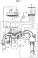
- FIG. 1 is a basic block diagram of an internal combustion engine to which a control system according to the present invention is applied, and an internal combustion engine 1 shown in the figure includes a piston 2, an intake valve 3 and an exhaust valve 4.
- An intake air passes an air flow meter (AFM) 20 and enters a throttle butterfly 19, and then is supplied to an intake pipe 10 via a collector 15 that is a branch part and further to a combustion chamber 21 of the internal combustion engine 1 via the intake valve 3.
- the fuel is provided from a fuel tank 23 to the internal combustion engine 1 by a low pressure fuel pump 24, and, further by a high pressure fuel pump 25, its pressure is increased to a pressure necessary for fuel injection.
- the fuel is supplied and injected from an injector 5 to the combustion chamber 21 of a cylinder 1a of the internal combustion engine 1, and ignited by a spark plug 6 using electric power supplied by a sparking coil 7.
- a pressure of fuel is being measured by a fuel pressure sensor 26.
- An exhaust gas after combustion is exhausted to an exhaust pipe 11 via an exhaust valve 4, and the exhaust pipe 11 includes a three-way catalyst 12 for cleaning the exhaust gas.
- the exhaust pipe 11 and the collector 15 are connected each other via an EGR (Exhaust Gas Recirculation) valve 14 and an EGR path 18, and thus an exhaust gas is mixed to an intake air.
- EGR exhaust Gas Recirculation
- a fuel injection control system 27 is incorporated, and signals such as a signal of a crank angle sensor 16, an air quantity signal of the AFM 20, a signal of an oxygen sensor 13 that detects an oxygen density in an exhaust gas, a signal of an accelerator open-rate of an accelerator open-rate sensor 22 and a signal of the fuel pressure sensor 26 are inputted to it.
- the ECU 9 calculates a required torque to the internal combustion engine from a signal of the accelerator open-rate sensor 22, and performs determination of an idle state and the like.
- the ECU 9 includes: rotation frequency detection means for calculating the number of rotations of the internal combustion engine from a signal of the crank angle sensor 16; and determination means for determining whether the three-way catalyst 12 is in the warmed-up state or not based on a water temperature of the internal combustion engine obtained from a water temperature sensor 8 and an elapsed time after starting of the internal combustion engine and the like.
- the ECU 9 calculates an intake air quantity required for the internal combustion engine 1 and outputs an open-rate signal consistent with the required intake air quantity to the throttle butterfly 19, and, in addition, the fuel injection control system 27 calculates a fuel quantity corresponding to the intake air quantity to output a fuel injection signal to the injector 5, and outputs an ignition signal to the spark plug 6.
- FIG. 2 indicates an embodiment of a configuration of a control system according to the present invention.
- the fuel injection control system 27 is incorporated, and the fuel injection control system 27 includes driving control means 28 for controlling driving of the injector 5. Based on a calculation result of the driving control means 28, a driving pulse is provided to the injector 5 for a plurality of times in a divided manner. Then, by a coil 5a of the injector 5 being applied an excitation current, its valve (not illustrated) is actuated and fuel is injected directly into the combustion chamber 21 of the internal combustion engine 1.
- a high voltage generation circuit 27a of the fuel injection control system 27 a high supply voltage needed for valve opening of the injector 5 is generated from a battery power of the internal combustion engine.
- the high supply voltage is converted into a desired supply voltage according to an instruction from a drive circuit 27d for generating a supply voltage.
- an injector drive circuit (Hi) 27b one of the high supply voltage and a low supply voltage which is a battery power is selected, and supplied to the injector 5.
- an injector drive circuit (Lo) 27c is a drive circuit, provided in the downstream side of the injector 5, for applying a driving current to the injector 5.
- the high voltage generation circuit 27a, the injector drive circuit (Hi) 27b and the injector drive circuit (Lo) 27c can supply a desired driving power supply and a driving current (excitation current) to the injector 5 to perform driving control of the injector 5.
- a driving period (a power applying time period to the injector), a driving power voltage and a driving current of the drive circuit 27d are controlled by a driving current waveform and the like calculated by the driving control means 28.
- the ECU 9 includes: air-fuel ratio detecting means 9a for detecting an air-fuel ratio of an internal combustion engine; operation status detecting means 9b for detecting an operation status of the internal combustion engine; injection count setting means 9c for setting the number of times of fuel injection (hereinafter, also referred to as a fuel injection count) based on an operation status of the internal combustion engine detected by the operation status detecting means 9b; and pulse width learning means 9d for learning an invalid pulse width.
- the driving control means 28 includes: pulse width calculation means 28a for, based on a learning result of the pulse width learning means 9d, calculating a pulse width of an excitation current for driving an injector to be valve-opened as valid pulse width corresponding to a fuel injection quantity and invalid pulse width corresponding to a valve opening delay and a valve closing delay of the injector; and driving waveform calculation means 28b for calculating driving waveform of the injector.
- the pulse width learning means 9d can also perform valid pulse width learning as needed. Also, each of valid pulse width and invalid pulse width can be learned by different pulse width learning means.
- the pulse width learning means 9d an amount of change in an air-fuel ratio of the air-fuel ratio detecting means 9a at the time when the number of times of fuel injection has been changed based on an internal combustion engine operation status of the operation status detecting means 9b is learned as an invalid pulse width of the pulse width calculation means 28a. Then, the valid pulse width and the invalid pulse width of the pulse width calculation means 28a are updated, and signals of the updated valid pulse width and the updated invalid pulse width of the injector are outputted to the drive circuit 27d and the driving waveform calculation means 28b.
- a driving current waveform is calculated and outputted to the drive circuit 27d.
- the high voltage generation circuit 27a, the injector drive circuit (Hi) 27b and the injector drive circuit (Lo) 27c are controlled based on these calculation results, and driving control of the injector 5 is performed by supplying a driving pulse to the injector 5.
- FIG. 3 indicates relation between an operation status of an internal combustion engine and the number of times of fuel injection to be set, and the horizontal axis of this figure shows the number of rotations, and the vertical axis a torque.
- the number of times of fuel injection is set from an operation status of an internal combustion engine. Further, it is supposed that the number of times of fuel injection is determined from a requirement for performance improvement of an internal combustion engine, a minimum injection pulse width by which an injector can perform injection accurately, the performance of a fuel injection control system and the like, and is calculated and set in the internal combustion engine control system in advance.
- FIG. 4 indicates an example of a time chart of an operation of an injector, and, with reference to this figure, relation between a pulse width for driving the injector to be opened, a valid pulse width corresponding to a fuel injection quantity, an invalid pulse width corresponding to a valve opening delay and a valve closing delay of the injector will be described.
- FIG. 4(A) shows an injector driving pulse signal in time series, 4(B) its driving current waveform, and 4(C) a valve operation in an injector.
- the injector driving pulse signal of FIG. 4(A) indicates a pulse width (TI) calculated by the pulse width learning means 9d and the pulse width calculation means 28a (refer to FIG. 2 ).
- the injector driving current waveform of FIG. 4(B) shows an example of a driving current waveform generated by the high voltage generation circuit 27a, the injector drive circuit (Hi) 27b and the injector drive circuit (Lo) 27c.
- a valve operation in the injector 5 actuated by an injector driving current waveform based on this injector driving pulse signal is shown in FIG. 4(C) . Meanwhile, the upper side of the figure indicates the valve-open state and the lower side the valve-close state.
- the injector completes a valve-open operation after a predetermined time interval (Td-OP-a) after the driving pulse signal has been supplied, and completes a valve-close operation after a predetermined time interval (Td-CL-a) after supply of the driving pulse signal has been stopped.
- These valve-open time (Td-OP-a) and valve-close time (Td-CL-a) form invalid pulse width of the injector, and a value that is made by subtracting the invalid pulse width from the total pulse width (TI) is controlled as valid pulse width.
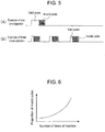
- FIG. 5(A) indicates relation between valid pulse width and invalid pulse width when a fuel injection count is set to 1
- FIG. 5(B) shows relation between valid pulse width and invalid pulse width when a fuel injection count is set to 3.
- an injection pulse width per time of injection becomes small, increasing proportion of invalid pulse width to an injection pulse width per time. This is caused by invalid pulse width existing for a given time period along with a valve operation of the injector independently of a required injection pulse width.
- Relation between a fuel injection count and a proportion of an invalid pulse to a fuel injection pulse described in FIG. 5 is indicated by a graph in FIG. 6 .
- a proportion of an invalid pulse increases further.
- FIG. 7 shows an example of a flow characteristic of an injector, and a dashed-dotted line indicates a basic characteristic of the injector, and a solid line in the both sides of the dashed-dotted line indicates a variation of the injector.
- a dashed-dotted line indicates a basic characteristic of the injector
- a solid line in the both sides of the dashed-dotted line indicates a variation of the injector.
- relation between a fuel injection pulse width and a fuel injection quantity in the cases of one time injection and three times injection under the same injection quantity condition As described in FIGS. 5 and 6 , also in this figure, relation between a difference in injection pulse widths per time according to a fuel injection count and a proportion of invalid pulse width to the fuel injection pulse width is shown. As shown, along with increase of a fuel injection count, that is, along with decrease of a fuel injection pulse width, a proportion of invalid pulse width is increased, and such difference in fuel injection counts relates to a variation of invalid pulse width associated with the injector. For this reason, in this embodiment, a variation of invalid pulse width of the injector is extracted using this feature to perform learning of invalid pulse width.
- FIG. 8 relation between an air-fuel ratio and performance of an internal combustion engine is indicated.
- the relation in this figure is generally known relation of an internal combustion engine, detailed description will be omitted, it can be seen that, even in the case of dividing fuel injection into a plurality of times of injection, performing air-fuel ratio control of an internal combustion engine accurately is indispensable because it leads to performance improvement of an internal combustion engine.
- FIG. 9 indicates conventional relation between a fuel injection count and an injector learning map, and the fuel injection counts that are shown are an example of injection counts set based on the relation shown in FIG. 3 .
- the grid indicated by a dashed line in the learning map indicates areas assigned for each operation range in order to perform learning of injection quantity of an injector, and a learning grid of an injector and a fuel injection count of an injector have independent relation with each other.
- FIG. 10 indicates an example of a time chart of injection quantity learning of an injector with respect to a change in a fuel injection count according to the present embodiment.
- FIG. 10(A) indicates a change in a fuel injection count in time series
- 10(B) a fuel injection pulse width per time
- 10(C) an air-fuel ratio.
- a pulse width decreases.
- a change in an air-fuel ratio of an internal combustion engine shown in FIG. 10(C) because, in reality, feedback control is carried out by an internal combustion engine control system using a signal of the oxygen sensor 13 (refer to FIG. 1 ) detecting an oxygen density in an exhaust gas, there is no cases where the air-fuel ratio change as indicated in this figure is maintained. However, for convenience of explanation, it is indicated such that a state where an air-fuel ratio has changed along with a change in a fuel injection count is maintained.
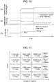
- the minimum allowable pulse width shown in FIG. 10(B) is a minimum pulse width with which the injector can perform injection accurately, and when a required injection pulse width becomes smaller than the minimum pulse width, invalid pulse width cannot be learned accurately. Accordingly, in such a case, learning of invalid pulse width should simply not be performed.
- the larger a proportion of an invalid pulse to a fuel injection pulse per time that is, the smaller a fuel injection pulse width per time
- FIG. 12 indicates an example of invalid pulse width learning according to a change of a fuel injection count using an injector learning map shown in FIG. 11 .
- FIG. 12(A) is a diagram illustrating a part of the learning map shown in FIG. 11
- FIGS. 12(B) and 12(C) are diagrams illustrating a change in a fuel injection count and a change in an air-fuel ratio, respectively, in time series.
- the grid shown in FIG. 12(A) indicates the grid of the injector learning map described in FIG. 11 .
- the arrow in the grid indicates an example of a change in a fuel injection count when an operation status of an internal combustion engine changes.
- a required fuel injection count of an injector is changed from A times to B times.
- the dashed line of a fuel injection count in FIG. 12(B) indicates such a required fuel injection count (it is corresponding to an injection count in a cell of the grid), and the solid line indicates an actual fuel injection count performed based on a required injection count.
- maintaining and continuing a previous fuel injection count without changing a fuel injection count for a predetermined period is preferable, because, when a state is changed from a small fuel injection count state to a large fuel injection count state, it is possible, thanks to such method, to perform fuel injection for a plurality of times without falling short of a minimum injection amount of the injector, and thus to perform control within a range in which the flow characteristic of an injector is secured.
- the previous fuel injection count does not need to be maintained and continued.
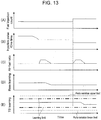
- FIG. 13 is a time chart describing an example of pulse width learning of an injector according to a change in a fuel injection count according to the present embodiment described using FIG. 12 further in detail.
- FIG. 13(A) is a diagram illustrating a fuel injection count in time series, 13(B) a fuel injection pulse width per time, and 13(C) a change in an air-fuel ratio.
- FIG. 13(D) is a diagram illustrating execution of valid pulse width learning in time series, and 13(E) execution of invalid pulse width learning. Meanwhile, regarding the air-fuel ratio shown in FIG. 13(C) , because, as described in FIG.
- An area of the first half of the indicated time chart shows a state where a fuel injection count being applied is not changed and where a change in an air-fuel ratio occurs due to a change in an operation status of an internal combustion engine.
- valid pulse width of an injector is learned (it is referred to as "Base learning").
- an area of the last half of the time chart indicates a state where a fuel injection count is changed as described using FIG. 12 , and, by this, where an air-fuel ratio change occurs.
- valid pulse width learning of an injector is not updated, and invalid pulse width learning of the injector (it is referred to as "TS learning") is updated.
- a parts variation upper limit and a parts variation lower limit shown by a dashed-dotted line of TS learning indicates an invalid pulse variation of an injector caused by a manufacturing error and a change over time.
- An update limitation (learning limitation) for invalid pulse width learning of the injector is provided so that update of invalid pulse width learning is carried out only within the range of the upper and lower values.
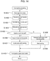
- FIG. 14 is a control flow chart of a control system according to the present embodiment.
- an operation status of an internal combustion engine is detected (S1401), then a required injection count of an injector is calculated based on the internal combustion engine operation status (S1402), and a fuel injection pulse width per time (TI) is calculated based on the internal combustion engine operation status and the required injection count (S1403).
- TI fuel injection pulse width per time
- an executive fuel injection count is calculated based on the required injection count and executed (S1404).
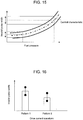
- FIGS. 15 and 16 indicate relation between: each of a fuel pressure applied to an injector and a pattern (profile) of a driving current waveform for driving the injector, which are potential variation factors; and invalid pulse width of the injector.
- the horizontal axis of FIG. 15 indicates a fuel pressure, and the vertical axis invalid pulse width of an injector.
- the dashed-dotted line indicates a central characteristic of the fuel pressure sensor 26 (refer to FIG. 1 ) for detecting a fuel pressure, and the solid lines above and below the dashed-dotted line indicate characteristic variations of the fuel pressure sensor.
- the learning accuracy can be improved.
- a valve-open time (Td-OP-a) and a valve-close time (Td-CL-a) of an injector are changed.
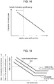
- a current value of an injector driving current waveform has a variation within a given range due to a variation of a drive circuit. Therefore, as shown in FIG. 16 , invalid pulse width of an injector is changed according to a pattern of an injector driving current waveform, and, further, by a variation specific to each current waveform, invalid pulse width of an injector also has a specific variation. Accordingly, as is the case with a fuel pressure applied to an injector, by learning invalid pulse width of the injector using a pattern of an injector driving current waveform as a parameter, its learning accuracy can be improved further.
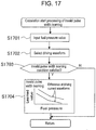
- FIG. 17 is a flow chart of invalid pulse width learning in the case where a variation factor such as a fuel pressure and a pattern of an injector driving current waveform as described above are used as a parameter.
- the learning flow shown in FIG. 17 can be modified accordingly, and, for example, whether a condition for fuel injection invalid pulse width learning is satisfied or not can be determined first, and after that, input processing of variation factors or the like is performed, and learning of invalid pulse width can be performed using them as a parameter.
- FIG. 18 a condition with which invalid pulse width learning is performed will be described.
- the figure is a diagram illustrating relation between a fuel injection pulse width per time and a proportion of an invalid pulse width to it.
- a proportion of an invalid pulse to a fuel injection pulse width is a predetermined value or more. That is, it is preferred to perform invalid pulse width learning when a fuel injection pulse width (injection quantity ratio) per time is not more than a predetermined value. Accordingly, as shown, by permitting invalid pulse width learning of an injector only when a fuel injection pulse width per time is within a predetermined range, it is possible to optimize such invalid pulse width learning and, further, simplify it.
- the embodiments of the present invention have been described in detail. According to the present invention, when performing fuel injection of an injector for a plurality of times according to an operation status of an internal combustion engine, it becomes possible to control a fuel injection quantity accurately by learning a variation of the injector, and as a result, it is possible to provide stable air-fuel ratio control of an internal combustion engine and to avoid degradation of exhaust gas emission and operability of the internal combustion engine.
Landscapes
- Engineering & Computer Science (AREA)
- Chemical & Material Sciences (AREA)
- Combustion & Propulsion (AREA)
- Mechanical Engineering (AREA)
- General Engineering & Computer Science (AREA)
- Electrical Control Of Air Or Fuel Supplied To Internal-Combustion Engine (AREA)
- Combined Controls Of Internal Combustion Engines (AREA)
Claims (8)
- Steuersystem einer Brennkraftmaschine, die eine Einspritzeinrichtung (5) besitzt, um ein Ventil zu betreiben und zu veranlassen, Kraftstoff einzuspritzen, indem in eine Spule ein Erregungsstrom eingegeben wird, und um den Kraftstoff direkt in eine Brennkammer (21) einzuspritzen,
wobei das Steuersystem Folgendes umfasst: Luft/Kraftstoff-Verhältnis-Detektionsmittel zum Detektieren eines Luft/Kraftstoff-Verhältnisses der Brennkraftmaschine (1); Betriebszustand-Detektionsmittel zum Detektieren eines Betriebszustands der Brennkraftmaschine (1); Einspritzzählwert-Einstellmittel zum Einstellen eines Kraftstoffeinspritzzählwerts auf eine von drei Einstellungen, wobei jede Einstellung eine andere Anzahl von Kraftstoffeinspritzzeiten besitzt, anhand des Betriebszustands der Brennkraftmaschine (1), der durch die Betriebszustand-Detektionsmittel detektiert wird, wenn der Betriebszustand der Kraftmaschinendrehzahl und dem Drehmoment entspricht, und der Kraftstoffeinspritzzählwert anhand der Kraftmaschinendrehzahl und des Drehmoments abgebildet wird; Ansteuerungsmittel zum Ausführen einer Ansteuerung einer Pulsbreite des Erregungsstroms, um die Ventilöffnung der Einspritzeinrichtung (5) anzusteuern; und Pulsbreiten-Lernmittel zum Lernen der Pulsbreite;
wobei die Ansteuerungsmittel eine gültige Pulsbreite berechnen, die einer Kraftstoffeinspritzmenge entspricht, die in die Brennkammer (21) eingespritzt wird, und eine ungültige Pulsbreite berechnen, die einer Ventilöffnungsverzögerung und einer Ventilschließverzögerung der Einspritzeinrichtung (5) entspricht;
dadurch gekennzeichnet, dass
die Pulsbreiten-Lernmittel anhand des Betriebszustands der Brennkraftmaschine (1) einen Änderungsbetrag des Luft/Kraftstoff-Verhältnisses zum Zeitpunkt einer Änderung des Kraftstoffeinspritzzählwerts auf eine der drei Einstellungen als die ungültige Pulsbreite lernen, wobei
dann, wenn ein Kraftstoffeinspritzzählwert durch die Einspritzzählwert-Einstellmittel eingestellt worden ist, ein Kraftstoffeinspritzzählwert nicht geändert wird bis zum Beginn des Lernens der ungültigen Pulsbreite der Einspritzeinrichtung, wobei der Beginn des Lernens der ungültigen Pulsbreite der Einspritzeinrichtung im selben Betriebszustand der Brennkraftmaschine ermöglicht wird. - Brennkraftmaschinen-Steuersystem nach Anspruch 1, wobei
dann, wenn ein Kraftstoffeinspritzzählwert nach einer Änderung eines Kraftstoffeinspritzzählwerts größer als ein Kraftstoffeinspritzzählwert vor der Änderung ist, der Kraftstoffeinspritzzählwert bis zum Beginn des Lernens der ungültigen Pulsbreite der Einspritzeinrichtung (5) nicht geändert wird, um eine Kraftstoffeinspritzung mehrfach auszuführen, ohne dass eine minimale Einspritzmenge der Einspritzeinrichtung (5) zu gering ist, um so die Steuerung in einem Bereich auszuführen, in dem die Strömungscharakteristik der Einspritzeinrichtung (5) gesichert ist. - Brennkraftmaschinen-Steuersystem nach Anspruch 1, wobei
dann, wenn eine Pulsbreite des Erregungsstroms pro Zeiteinheit zur Zeit einer mehrfach unterteilten Einspritzung von Kraftstoff in die Brennkammer (21) in einem vorgegebenen Bereich liegt, die Pulsbreitenlernmittel die ungültige Pulsbreite lernen. - Brennkraftmaschinen-Steuersystem nach Anspruch 1, wobei
dann, wenn jede Einspritzpulsbreite pro Zeiteinheit zur Zeit einer mehrfach unterteilten Einspritzung von Kraftstoff in die Brennkammer in einem vorgegebenen Bereich liegt, die Pulsbreiten-Lernmittel die ungültige Pulsbreite lernen. - Brennkraftmaschinen-Steuersystem nach Anspruch 1, wobei
die Pulsbreiten-Lernmittel die ungültige Pulsbreite unter Verwendung eines Kraftstoffdrucks, der auf die Einspritzeinrichtung der Brennkraftmaschine (1) ausgeübt wird, und/oder ein Muster eines Erregungsstroms, der in die Einspritzeinrichtung eingegeben wird, als einen Parameter verwenden. - Brennkraftmaschinen-Steuersystem nach Anspruch 1, wobei
die ungültige Pulsbreite, die durch die Pulsbreiten-Lernmittel gelernt werden soll, auf einen Einstellbereich, der im Voraus eingestellt worden ist, begrenzt ist. - Brennkraftmaschinen-Steuersystem nach Anspruch 5, wobei
die Pulsbreiten-Lernmittel die gültige Pulsbreite und die ungültige Pulsbreite anhand des Luft/Kraftstoff-Verhältnisses, das durch die Luft/Kraftstoff-Verhältnis-Detektionsmittel detektiert wird, lernen und wobei
die Pulsbreiten-Lernmittel einen Änderungsbetrag des Luft/Kraftstoff-Verhältnisses dann, wenn sich ein Kraftstoffeinspritzzählwert geändert hat, als die ungültige Pulsbreite der Einspritzeinrichtung lernen und einen Änderungsbetrag des Luft/Kraftstoff-Verhältnisses dann, wenn sich ein Kraftstoffeinspritzzählwert nicht geändert hat, als die gültige Pulsbreite der Einspritzeinrichtung (5) lernen. - Brennkraftmaschinen-Steuersystem nach Anspruch 7, wobei
das Lernen von Aktualisierungen der gültigen Pulsbreite und der ungültigen Pulsbreite der Einspritzeinrichtung nicht gleichzeitig ausgeführt wird, sondern dass dann, wenn eine der Aktualisierungen beendet worden ist, die andere Aktualisierung ausgeführt wird.
Applications Claiming Priority (1)
| Application Number | Priority Date | Filing Date | Title |
|---|---|---|---|
| JP2010247679A JP5759142B2 (ja) | 2010-11-04 | 2010-11-04 | 内燃機関の制御装置 |
Publications (3)
| Publication Number | Publication Date |
|---|---|
| EP2450552A2 EP2450552A2 (de) | 2012-05-09 |
| EP2450552A3 EP2450552A3 (de) | 2015-03-11 |
| EP2450552B1 true EP2450552B1 (de) | 2017-06-21 |
Family
ID=44925378
Family Applications (1)
| Application Number | Title | Priority Date | Filing Date |
|---|---|---|---|
| EP11187576.1A Active EP2450552B1 (de) | 2010-11-04 | 2011-11-02 | Steuersystem eines Verbrennungsmotors |
Country Status (4)
| Country | Link |
|---|---|
| US (1) | US8862367B2 (de) |
| EP (1) | EP2450552B1 (de) |
| JP (1) | JP5759142B2 (de) |
| CN (1) | CN102454500B (de) |
Families Citing this family (21)
| Publication number | Priority date | Publication date | Assignee | Title |
|---|---|---|---|---|
| US8365698B2 (en) | 2004-01-12 | 2013-02-05 | Liquidpiston, Inc. | Hybrid cycle combustion engine and methods |
| US8863724B2 (en) | 2008-08-04 | 2014-10-21 | Liquidpiston, Inc. | Isochoric heat addition engines and methods |
| EP2469064A1 (de) * | 2010-12-24 | 2012-06-27 | Delphi Technologies, Inc. | Verfahren zur Steuerung eines Verbrennungsmotors |
| US9243580B2 (en) * | 2011-12-07 | 2016-01-26 | Ford Global Technologies, Llc | Method and system for reducing soot formed by an engine |
| JP5790611B2 (ja) * | 2012-09-13 | 2015-10-07 | 株式会社デンソー | 燃料噴射制御装置 |
| JP6011447B2 (ja) | 2013-05-10 | 2016-10-19 | トヨタ自動車株式会社 | 燃料噴射弁の制御装置 |
| KR101491271B1 (ko) * | 2013-07-05 | 2015-02-06 | 현대자동차주식회사 | 차량의 연료펌프 제어방법 및 전자제어 컨트롤러 |
| JP6213085B2 (ja) * | 2013-09-17 | 2017-10-18 | 株式会社デンソー | 内燃機関の気筒別空燃比制御装置 |
| CN106605057B (zh) * | 2014-08-29 | 2020-05-15 | 日立汽车系统株式会社 | 内燃机控制装置 |
| DE102014223864A1 (de) | 2014-11-24 | 2016-05-25 | Robert Bosch Gmbh | Verfahren zur Erkennung eines Spannungsoffsets zumindest in einem Bereich bei einer Spannungs-Lambda-Kennlinie |
| JP6323684B2 (ja) * | 2015-06-03 | 2018-05-16 | マツダ株式会社 | エンジンの制御装置 |
| JP6323683B2 (ja) * | 2015-06-03 | 2018-05-16 | マツダ株式会社 | エンジンの制御装置 |
| WO2017006814A1 (ja) * | 2015-07-09 | 2017-01-12 | 日立オートモティブシステムズ株式会社 | 燃料噴射装置の制御装置 |
| CN108138712B (zh) * | 2015-10-20 | 2020-12-29 | 日立汽车系统株式会社 | 车辆用控制装置 |
| CN108474312B (zh) * | 2016-01-14 | 2019-04-26 | 日产自动车株式会社 | 缸内直喷式内燃机的控制方法以及控制装置 |
| US10330040B2 (en) * | 2016-06-14 | 2019-06-25 | Ford Global Technologies, Llc | Method and system for air-fuel ratio control |
| JP6390670B2 (ja) | 2016-07-12 | 2018-09-19 | トヨタ自動車株式会社 | エンジンの燃料噴射制御装置 |
| US20190010889A1 (en) * | 2017-07-07 | 2019-01-10 | GM Global Technology Operations LLC | Optimization of current injection profile for solenoid injectors |
| US11236697B2 (en) * | 2018-02-26 | 2022-02-01 | Hitachi Automotive Systems, Ltd. | Fuel injection control device and fuel injection control method |
| JP7412606B2 (ja) * | 2021-01-12 | 2024-01-12 | 日立Astemo株式会社 | 燃料噴射制御装置 |
| US20260022675A1 (en) * | 2024-07-19 | 2026-01-22 | Caterpillar Inc. | System and method for adjusting fuel injector commands |
Family Cites Families (15)
| Publication number | Priority date | Publication date | Assignee | Title |
|---|---|---|---|---|
| JPH06257497A (ja) * | 1993-03-09 | 1994-09-13 | Mazda Motor Corp | エンジンの燃料噴射制御装置およびその方法 |
| JPH08284716A (ja) * | 1995-04-14 | 1996-10-29 | Daihatsu Motor Co Ltd | 内燃機関の空燃比学習制御方法 |
| JPH09166040A (ja) * | 1995-12-13 | 1997-06-24 | Matsushita Electric Ind Co Ltd | 内燃機関の空燃比制御装置 |
| JP3644172B2 (ja) * | 1997-01-16 | 2005-04-27 | 日産自動車株式会社 | エンジンの空燃比制御装置 |
| JPH11343911A (ja) * | 1998-03-31 | 1999-12-14 | Mazda Motor Corp | 筒内噴射式エンジンの燃料制御装置 |
| JP2000234549A (ja) * | 1999-02-12 | 2000-08-29 | Fuji Heavy Ind Ltd | エンジンの制御装置 |
| JP3965947B2 (ja) * | 2001-07-25 | 2007-08-29 | 日産自動車株式会社 | エンジンの空燃比制御装置 |
| FR2857700B1 (fr) * | 2003-07-16 | 2005-09-30 | Magneti Marelli Motopropulsion | Procede de determination en temps reel de la caracteristique de debit d'injecteur de carburant |
| JP4428201B2 (ja) * | 2004-11-01 | 2010-03-10 | 株式会社デンソー | 蓄圧式燃料噴射装置 |
| JP4815407B2 (ja) * | 2007-08-31 | 2011-11-16 | 本田技研工業株式会社 | 内燃機関の運転制御装置 |
| DE102008006327A1 (de) * | 2008-01-28 | 2009-07-30 | Robert Bosch Gmbh | Verfahren zur Steuerung einer Brennkraftmaschine |
| ATE487864T1 (de) * | 2008-04-08 | 2010-11-15 | Magneti Marelli Spa | Verfahren zur bestimmung des tatsächlichen versatzwerts einer einspritzdüse eines verbrennungsmotors |
| US8037874B2 (en) * | 2008-06-11 | 2011-10-18 | Ford Global Technologies, Llc | Fuel based cylinder knock control |
| JP2011052670A (ja) * | 2009-09-04 | 2011-03-17 | Denso Corp | 内燃機関の燃料噴射装置 |
| JP2011179389A (ja) * | 2010-02-26 | 2011-09-15 | Denso Corp | 内燃機関の燃料噴射制御装置 |
-
2010
- 2010-11-04 JP JP2010247679A patent/JP5759142B2/ja not_active Expired - Fee Related
-
2011
- 2011-11-01 CN CN201110340067.6A patent/CN102454500B/zh active Active
- 2011-11-02 EP EP11187576.1A patent/EP2450552B1/de active Active
- 2011-11-03 US US13/288,438 patent/US8862367B2/en active Active
Also Published As
| Publication number | Publication date |
|---|---|
| CN102454500B (zh) | 2015-05-27 |
| CN102454500A (zh) | 2012-05-16 |
| US8862367B2 (en) | 2014-10-14 |
| EP2450552A2 (de) | 2012-05-09 |
| EP2450552A3 (de) | 2015-03-11 |
| JP5759142B2 (ja) | 2015-08-05 |
| JP2012097693A (ja) | 2012-05-24 |
| US20120116654A1 (en) | 2012-05-10 |
Similar Documents
| Publication | Publication Date | Title |
|---|---|---|
| EP2450552B1 (de) | Steuersystem eines Verbrennungsmotors | |
| CN111594334B (zh) | 高压共轨发动机的燃料喷射控制的方法和系统 | |
| CN103270280B (zh) | 控制内燃机的方法 | |
| US7778765B2 (en) | Fuel injection control apparatus for internal combustion engine | |
| EP2592256B1 (de) | Vorrichtung zur steuerung der kraftstoffeinspritzung für einen verbrennungsmotor | |
| CN100467842C (zh) | 内燃机控制设备 | |
| US20110106409A1 (en) | Method and device for the pressure wave compensation during consecutive injections in an injection system of an internal combustion engine | |
| EP1316702B1 (de) | Vorrichtung zur Regelung der Abgasrückführung einer Brennkraftmaschine | |
| EP2039918A1 (de) | Vorrichtung zur Steuerung der Kraftstoffeinspritzung für einen Verbrennungsmotor | |
| US20100116911A1 (en) | Method and device for the calibration of fuel injectors | |
| EP0980471A1 (de) | Methode für einen kontrollierten übergang zwischen betriebsarten einer zweikraftstoffmaschine | |
| CN105051354A (zh) | 燃料喷射阀的控制装置 | |
| CN101907029A (zh) | 用于调节小燃料喷射量的方法和系统 | |
| US20130180511A1 (en) | Method for operating an internal combustion engine having multiple combustion chambers, and internal combustion engine having multiple combustion chambers | |
| CN107237700B (zh) | 用于调整燃料配量的方法 | |
| JP2009057853A (ja) | 内燃機関の燃料噴射制御装置及び内燃機関の燃料噴射量学習方法 | |
| US20240219263A1 (en) | Method of determining a hydraulic timing of a fuel injector | |
| CN114364868B (zh) | 用于控制多次喷射中的总喷射量的方法 | |
| EP2420664A1 (de) | Verfahren zur Steuerung eines Verbrennungsmotors | |
| KR101744732B1 (ko) | 인젝터의 출력 전압을 이용한 고장 진단 방법 | |
| KR101786990B1 (ko) | 시험 구동을 통한 gdi 엔진의 인젝터 제어 방법 | |
| KR101787037B1 (ko) | 인젝터 폐쇄 시점 학습시 인젝션 제어 방법 및 장치 |
Legal Events
| Date | Code | Title | Description |
|---|---|---|---|
| PUAI | Public reference made under article 153(3) epc to a published international application that has entered the european phase |
Free format text: ORIGINAL CODE: 0009012 |
|
| 17P | Request for examination filed |
Effective date: 20120302 |
|
| AK | Designated contracting states |
Kind code of ref document: A2 Designated state(s): AL AT BE BG CH CY CZ DE DK EE ES FI FR GB GR HR HU IE IS IT LI LT LU LV MC MK MT NL NO PL PT RO RS SE SI SK SM TR |
|
| AX | Request for extension of the european patent |
Extension state: BA ME |
|
| PUAL | Search report despatched |
Free format text: ORIGINAL CODE: 0009013 |
|
| AK | Designated contracting states |
Kind code of ref document: A3 Designated state(s): AL AT BE BG CH CY CZ DE DK EE ES FI FR GB GR HR HU IE IS IT LI LT LU LV MC MK MT NL NO PL PT RO RS SE SI SK SM TR |
|
| AX | Request for extension of the european patent |
Extension state: BA ME |
|
| RIC1 | Information provided on ipc code assigned before grant |
Ipc: F02D 41/40 20060101ALI20150204BHEP Ipc: F02D 41/24 20060101AFI20150204BHEP Ipc: F02D 41/20 20060101ALI20150204BHEP Ipc: F02D 41/14 20060101ALI20150204BHEP |
|
| 17Q | First examination report despatched |
Effective date: 20160609 |
|
| GRAP | Despatch of communication of intention to grant a patent |
Free format text: ORIGINAL CODE: EPIDOSNIGR1 |
|
| STAA | Information on the status of an ep patent application or granted ep patent |
Free format text: STATUS: GRANT OF PATENT IS INTENDED |
|
| INTG | Intention to grant announced |
Effective date: 20170119 |
|
| GRAS | Grant fee paid |
Free format text: ORIGINAL CODE: EPIDOSNIGR3 |
|
| GRAA | (expected) grant |
Free format text: ORIGINAL CODE: 0009210 |
|
| STAA | Information on the status of an ep patent application or granted ep patent |
Free format text: STATUS: THE PATENT HAS BEEN GRANTED |
|
| AK | Designated contracting states |
Kind code of ref document: B1 Designated state(s): AL AT BE BG CH CY CZ DE DK EE ES FI FR GB GR HR HU IE IS IT LI LT LU LV MC MK MT NL NO PL PT RO RS SE SI SK SM TR |
|
| REG | Reference to a national code |
Ref country code: GB Ref legal event code: FG4D |
|
| RIN1 | Information on inventor provided before grant (corrected) |
Inventor name: TOYOHARA, MASAHIRO Inventor name: FUJII, YOSHIHISA |
|
| REG | Reference to a national code |
Ref country code: CH Ref legal event code: EP |
|
| REG | Reference to a national code |
Ref country code: IE Ref legal event code: FG4D |
|
| REG | Reference to a national code |
Ref country code: AT Ref legal event code: REF Ref document number: 903172 Country of ref document: AT Kind code of ref document: T Effective date: 20170715 |
|
| REG | Reference to a national code |
Ref country code: DE Ref legal event code: R096 Ref document number: 602011038865 Country of ref document: DE |
|
| REG | Reference to a national code |
Ref country code: NL Ref legal event code: MP Effective date: 20170621 |
|
| PG25 | Lapsed in a contracting state [announced via postgrant information from national office to epo] |
Ref country code: GR Free format text: LAPSE BECAUSE OF FAILURE TO SUBMIT A TRANSLATION OF THE DESCRIPTION OR TO PAY THE FEE WITHIN THE PRESCRIBED TIME-LIMIT Effective date: 20170922 Ref country code: NO Free format text: LAPSE BECAUSE OF FAILURE TO SUBMIT A TRANSLATION OF THE DESCRIPTION OR TO PAY THE FEE WITHIN THE PRESCRIBED TIME-LIMIT Effective date: 20170921 Ref country code: HR Free format text: LAPSE BECAUSE OF FAILURE TO SUBMIT A TRANSLATION OF THE DESCRIPTION OR TO PAY THE FEE WITHIN THE PRESCRIBED TIME-LIMIT Effective date: 20170621 Ref country code: LT Free format text: LAPSE BECAUSE OF FAILURE TO SUBMIT A TRANSLATION OF THE DESCRIPTION OR TO PAY THE FEE WITHIN THE PRESCRIBED TIME-LIMIT Effective date: 20170621 Ref country code: FI Free format text: LAPSE BECAUSE OF FAILURE TO SUBMIT A TRANSLATION OF THE DESCRIPTION OR TO PAY THE FEE WITHIN THE PRESCRIBED TIME-LIMIT Effective date: 20170621 |
|
| REG | Reference to a national code |
Ref country code: LT Ref legal event code: MG4D |
|
| REG | Reference to a national code |
Ref country code: AT Ref legal event code: MK05 Ref document number: 903172 Country of ref document: AT Kind code of ref document: T Effective date: 20170621 |
|
| PG25 | Lapsed in a contracting state [announced via postgrant information from national office to epo] |
Ref country code: SE Free format text: LAPSE BECAUSE OF FAILURE TO SUBMIT A TRANSLATION OF THE DESCRIPTION OR TO PAY THE FEE WITHIN THE PRESCRIBED TIME-LIMIT Effective date: 20170621 Ref country code: LV Free format text: LAPSE BECAUSE OF FAILURE TO SUBMIT A TRANSLATION OF THE DESCRIPTION OR TO PAY THE FEE WITHIN THE PRESCRIBED TIME-LIMIT Effective date: 20170621 Ref country code: RS Free format text: LAPSE BECAUSE OF FAILURE TO SUBMIT A TRANSLATION OF THE DESCRIPTION OR TO PAY THE FEE WITHIN THE PRESCRIBED TIME-LIMIT Effective date: 20170621 Ref country code: BG Free format text: LAPSE BECAUSE OF FAILURE TO SUBMIT A TRANSLATION OF THE DESCRIPTION OR TO PAY THE FEE WITHIN THE PRESCRIBED TIME-LIMIT Effective date: 20170921 Ref country code: NL Free format text: LAPSE BECAUSE OF FAILURE TO SUBMIT A TRANSLATION OF THE DESCRIPTION OR TO PAY THE FEE WITHIN THE PRESCRIBED TIME-LIMIT Effective date: 20170621 |
|
| PG25 | Lapsed in a contracting state [announced via postgrant information from national office to epo] |
Ref country code: CZ Free format text: LAPSE BECAUSE OF FAILURE TO SUBMIT A TRANSLATION OF THE DESCRIPTION OR TO PAY THE FEE WITHIN THE PRESCRIBED TIME-LIMIT Effective date: 20170621 Ref country code: RO Free format text: LAPSE BECAUSE OF FAILURE TO SUBMIT A TRANSLATION OF THE DESCRIPTION OR TO PAY THE FEE WITHIN THE PRESCRIBED TIME-LIMIT Effective date: 20170621 Ref country code: SK Free format text: LAPSE BECAUSE OF FAILURE TO SUBMIT A TRANSLATION OF THE DESCRIPTION OR TO PAY THE FEE WITHIN THE PRESCRIBED TIME-LIMIT Effective date: 20170621 Ref country code: AT Free format text: LAPSE BECAUSE OF FAILURE TO SUBMIT A TRANSLATION OF THE DESCRIPTION OR TO PAY THE FEE WITHIN THE PRESCRIBED TIME-LIMIT Effective date: 20170621 Ref country code: EE Free format text: LAPSE BECAUSE OF FAILURE TO SUBMIT A TRANSLATION OF THE DESCRIPTION OR TO PAY THE FEE WITHIN THE PRESCRIBED TIME-LIMIT Effective date: 20170621 |
|
| PG25 | Lapsed in a contracting state [announced via postgrant information from national office to epo] |
Ref country code: ES Free format text: LAPSE BECAUSE OF FAILURE TO SUBMIT A TRANSLATION OF THE DESCRIPTION OR TO PAY THE FEE WITHIN THE PRESCRIBED TIME-LIMIT Effective date: 20170621 Ref country code: IT Free format text: LAPSE BECAUSE OF FAILURE TO SUBMIT A TRANSLATION OF THE DESCRIPTION OR TO PAY THE FEE WITHIN THE PRESCRIBED TIME-LIMIT Effective date: 20170621 Ref country code: PL Free format text: LAPSE BECAUSE OF FAILURE TO SUBMIT A TRANSLATION OF THE DESCRIPTION OR TO PAY THE FEE WITHIN THE PRESCRIBED TIME-LIMIT Effective date: 20170621 Ref country code: SM Free format text: LAPSE BECAUSE OF FAILURE TO SUBMIT A TRANSLATION OF THE DESCRIPTION OR TO PAY THE FEE WITHIN THE PRESCRIBED TIME-LIMIT Effective date: 20170621 Ref country code: IS Free format text: LAPSE BECAUSE OF FAILURE TO SUBMIT A TRANSLATION OF THE DESCRIPTION OR TO PAY THE FEE WITHIN THE PRESCRIBED TIME-LIMIT Effective date: 20171021 |
|
| REG | Reference to a national code |
Ref country code: DE Ref legal event code: R097 Ref document number: 602011038865 Country of ref document: DE |
|
| PLBE | No opposition filed within time limit |
Free format text: ORIGINAL CODE: 0009261 |
|
| STAA | Information on the status of an ep patent application or granted ep patent |
Free format text: STATUS: NO OPPOSITION FILED WITHIN TIME LIMIT |
|
| PG25 | Lapsed in a contracting state [announced via postgrant information from national office to epo] |
Ref country code: DK Free format text: LAPSE BECAUSE OF FAILURE TO SUBMIT A TRANSLATION OF THE DESCRIPTION OR TO PAY THE FEE WITHIN THE PRESCRIBED TIME-LIMIT Effective date: 20170621 |
|
| 26N | No opposition filed |
Effective date: 20180322 |
|
| PG25 | Lapsed in a contracting state [announced via postgrant information from national office to epo] |
Ref country code: MC Free format text: LAPSE BECAUSE OF FAILURE TO SUBMIT A TRANSLATION OF THE DESCRIPTION OR TO PAY THE FEE WITHIN THE PRESCRIBED TIME-LIMIT Effective date: 20170621 |
|
| GBPC | Gb: european patent ceased through non-payment of renewal fee |
Effective date: 20171102 |
|
| PG25 | Lapsed in a contracting state [announced via postgrant information from national office to epo] |
Ref country code: CH Free format text: LAPSE BECAUSE OF NON-PAYMENT OF DUE FEES Effective date: 20171130 Ref country code: LI Free format text: LAPSE BECAUSE OF NON-PAYMENT OF DUE FEES Effective date: 20171130 |
|
| PG25 | Lapsed in a contracting state [announced via postgrant information from national office to epo] |
Ref country code: LU Free format text: LAPSE BECAUSE OF NON-PAYMENT OF DUE FEES Effective date: 20171102 Ref country code: SI Free format text: LAPSE BECAUSE OF FAILURE TO SUBMIT A TRANSLATION OF THE DESCRIPTION OR TO PAY THE FEE WITHIN THE PRESCRIBED TIME-LIMIT Effective date: 20170621 |
|
| REG | Reference to a national code |
Ref country code: FR Ref legal event code: ST Effective date: 20180731 Ref country code: BE Ref legal event code: MM Effective date: 20171130 |
|
| REG | Reference to a national code |
Ref country code: IE Ref legal event code: MM4A |
|
| PG25 | Lapsed in a contracting state [announced via postgrant information from national office to epo] |
Ref country code: MT Free format text: LAPSE BECAUSE OF NON-PAYMENT OF DUE FEES Effective date: 20171102 |
|
| PG25 | Lapsed in a contracting state [announced via postgrant information from national office to epo] |
Ref country code: FR Free format text: LAPSE BECAUSE OF NON-PAYMENT OF DUE FEES Effective date: 20171130 Ref country code: IE Free format text: LAPSE BECAUSE OF NON-PAYMENT OF DUE FEES Effective date: 20171102 |
|
| PG25 | Lapsed in a contracting state [announced via postgrant information from national office to epo] |
Ref country code: BE Free format text: LAPSE BECAUSE OF NON-PAYMENT OF DUE FEES Effective date: 20171130 Ref country code: GB Free format text: LAPSE BECAUSE OF NON-PAYMENT OF DUE FEES Effective date: 20171102 |
|
| PG25 | Lapsed in a contracting state [announced via postgrant information from national office to epo] |
Ref country code: HU Free format text: LAPSE BECAUSE OF FAILURE TO SUBMIT A TRANSLATION OF THE DESCRIPTION OR TO PAY THE FEE WITHIN THE PRESCRIBED TIME-LIMIT; INVALID AB INITIO Effective date: 20111102 |
|
| PG25 | Lapsed in a contracting state [announced via postgrant information from national office to epo] |
Ref country code: CY Free format text: LAPSE BECAUSE OF NON-PAYMENT OF DUE FEES Effective date: 20170621 |
|
| PG25 | Lapsed in a contracting state [announced via postgrant information from national office to epo] |
Ref country code: MK Free format text: LAPSE BECAUSE OF FAILURE TO SUBMIT A TRANSLATION OF THE DESCRIPTION OR TO PAY THE FEE WITHIN THE PRESCRIBED TIME-LIMIT Effective date: 20170621 |
|
| PG25 | Lapsed in a contracting state [announced via postgrant information from national office to epo] |
Ref country code: TR Free format text: LAPSE BECAUSE OF FAILURE TO SUBMIT A TRANSLATION OF THE DESCRIPTION OR TO PAY THE FEE WITHIN THE PRESCRIBED TIME-LIMIT Effective date: 20170621 |
|
| PG25 | Lapsed in a contracting state [announced via postgrant information from national office to epo] |
Ref country code: PT Free format text: LAPSE BECAUSE OF FAILURE TO SUBMIT A TRANSLATION OF THE DESCRIPTION OR TO PAY THE FEE WITHIN THE PRESCRIBED TIME-LIMIT Effective date: 20170621 |
|
| PG25 | Lapsed in a contracting state [announced via postgrant information from national office to epo] |
Ref country code: AL Free format text: LAPSE BECAUSE OF FAILURE TO SUBMIT A TRANSLATION OF THE DESCRIPTION OR TO PAY THE FEE WITHIN THE PRESCRIBED TIME-LIMIT Effective date: 20170621 |
|
| REG | Reference to a national code |
Ref country code: DE Ref legal event code: R082 Ref document number: 602011038865 Country of ref document: DE Representative=s name: MERH-IP MATIAS ERNY REICHL HOFFMANN PATENTANWA, DE Ref country code: DE Ref legal event code: R081 Ref document number: 602011038865 Country of ref document: DE Owner name: HITACHI ASTEMO, LTD., HITACHINAKA-SHI, JP Free format text: FORMER OWNER: HITACHI AUTOMOTIVE SYSTEMS, LTD., HITACHINAKA-SHI, IBARAKI, JP |
|
| PGFP | Annual fee paid to national office [announced via postgrant information from national office to epo] |
Ref country code: DE Payment date: 20241001 Year of fee payment: 14 |