EP2447697B1 - Vorverarbeitungsvorrichtung - Google Patents
Vorverarbeitungsvorrichtung Download PDFInfo
- Publication number
- EP2447697B1 EP2447697B1 EP10792160.3A EP10792160A EP2447697B1 EP 2447697 B1 EP2447697 B1 EP 2447697B1 EP 10792160 A EP10792160 A EP 10792160A EP 2447697 B1 EP2447697 B1 EP 2447697B1
- Authority
- EP
- European Patent Office
- Prior art keywords
- cartridge
- phase extraction
- solid
- holders
- transport means
- Prior art date
- Legal status (The legal status is an assumption and is not a legal conclusion. Google has not performed a legal analysis and makes no representation as to the accuracy of the status listed.)
- Not-in-force
Links
Images



Classifications
-
- G—PHYSICS
- G01—MEASURING; TESTING
- G01N—INVESTIGATING OR ANALYSING MATERIALS BY DETERMINING THEIR CHEMICAL OR PHYSICAL PROPERTIES
- G01N1/00—Sampling; Preparing specimens for investigation
- G01N1/28—Preparing specimens for investigation including physical details of (bio-)chemical methods covered elsewhere, e.g. G01N33/50, C12Q
- G01N1/40—Concentrating samples
- G01N1/4055—Concentrating samples by solubility techniques
-
- G—PHYSICS
- G01—MEASURING; TESTING
- G01N—INVESTIGATING OR ANALYSING MATERIALS BY DETERMINING THEIR CHEMICAL OR PHYSICAL PROPERTIES
- G01N35/00—Automatic analysis not limited to methods or materials provided for in any single one of groups G01N1/00 - G01N33/00; Handling materials therefor
- G01N35/02—Automatic analysis not limited to methods or materials provided for in any single one of groups G01N1/00 - G01N33/00; Handling materials therefor using a plurality of sample containers moved by a conveyor system past one or more treatment or analysis stations
- G01N35/025—Automatic analysis not limited to methods or materials provided for in any single one of groups G01N1/00 - G01N33/00; Handling materials therefor using a plurality of sample containers moved by a conveyor system past one or more treatment or analysis stations having a carousel or turntable for reaction cells or cuvettes
-
- G—PHYSICS
- G01—MEASURING; TESTING
- G01N—INVESTIGATING OR ANALYSING MATERIALS BY DETERMINING THEIR CHEMICAL OR PHYSICAL PROPERTIES
- G01N1/00—Sampling; Preparing specimens for investigation
- G01N1/28—Preparing specimens for investigation including physical details of (bio-)chemical methods covered elsewhere, e.g. G01N33/50, C12Q
- G01N1/40—Concentrating samples
- G01N1/4055—Concentrating samples by solubility techniques
- G01N2001/4061—Solvent extraction
-
- G—PHYSICS
- G01—MEASURING; TESTING
- G01N—INVESTIGATING OR ANALYSING MATERIALS BY DETERMINING THEIR CHEMICAL OR PHYSICAL PROPERTIES
- G01N30/00—Investigating or analysing materials by separation into components using adsorption, absorption or similar phenomena or using ion-exchange, e.g. chromatography or field flow fractionation
- G01N2030/009—Extraction
-
- H—ELECTRICITY
- H01—ELECTRIC ELEMENTS
- H01J—ELECTRIC DISCHARGE TUBES OR DISCHARGE LAMPS
- H01J49/00—Particle spectrometers or separator tubes
Definitions
- the present invention relates to a pretreatment apparatus that assays constituents contained in a biological sample of blood and serum or the like, and a mass analyzing instrument equipped with the same.
- trace compounds e.g., drugs
- a biological sample such as blood and serum or the like
- purify and concentrate the compounds since the constituents to be assayed are in very small quantities.
- Solid-phase extraction is a method of separating, purifying, and concentrating an analyte (or a substance to be assayed), by retaining this substance in a solid phase extracting agent (e.g., a plurality of small beads or membrane-like substances) in packed form in a small container such as a minicolumn or cartridge, then washing the solid phase extracting agent , and collecting desired compounds from the solid phase extracting agent.
- a solid phase extracting agent e.g., a plurality of small beads or membrane-like substances
- the step of collecting the desired compounds by the solid phase extraction includes five process steps: (1) a solid-phase extracting agent conditioning step in which to pass an organic solvent through the solid phase extracting agent , (2) a solid-phase equilibrating step in which to pass a water-based solvent through the solid phase extracting agent , (3) the step of retaining the analyte in the solid phase extracting agent by passing the sample through the solid phase extracting agent , (4) a washing step in which to pass water through the solid phase extracting agent , and (5) the step of passing the organic solvent through the solid phase extracting agent and eluting the analyte from the solid phase extracting agent.
- the automatic solid-phase extraction apparatus described therein includes a vacuum rack equipped with a multiple solid-phase plate bank, a dispensing head that suctions and discharges a liquid, and means that transfers the dispensing head.
- the above conventional extraction apparatus enables a batch-processing (using 96 holes plate) capability and an ability to purify and concentrate analyte constituents in blood, serum, and the like, automatically.
- the solution containing purified and concentrated analytes, thus obtained, are transferred to a liquid-chromatography or a mass spectrometry instrument for qualitative and quantitative analyses of the trace analyte substances, e.g., drugs, contained in the biological sample, such as blood and serum or the like.
- This technique adopted in the conventional extraction apparatus is effective in that conventional manual pretreatment by the analyzing person prior to mass spectrometry has been automated, so as to accelerate significant reduction in time and in statistical variations in data.
- Patent Document 1 JP-2006-7081-A
- dispensing tips are changed in each step of solvent suctioning and discharging, moving the dispensing head to a dispensing tip container by the transfer means.
- the solid-phase extraction steps use multiple kinds of solvents (a water-based solvent and an organic solvent).
- step (1) discussed above uses the organic solvent
- step (2) uses the water-based solvent.
- This has required changing dispensing tips with each change of the kind of solvent, thus causing increases in the quantity of dispensing tips discarded and in costs of consumables.
- the dispensing head needs to move among tip-mounting position, solvent-suctioning position, and solvent-discharging position, it takes a long time to move, resulting in an extended cycle time and hence in reduced throughput.
- the dispensing head is of multiple tip construction and thus since the apparatus is constructed to conduct successive solid-phase extracting operations by using a plurality of samples of the same kind at the same time, a plurality of tips need to be mounted on the dispensing head to perform solid-phase extraction of one sample, for example. Accordingly, solvents as many as dispensing tips were actually discarded, resulting in unnecessary waste of consumables.
- An object of the present invention is to achieve a pretreatment apparatus using a minimum number of consumables and capable of conducting multi-item separation and purification of an analyte in a series of solid-phase extraction steps with high efficiency. Another object is to achieve a mass analyzing apparatus quipped with the pretreatment apparatus.
- the present invention is configured as follows.
- the biological sample pretreatment apparatus of the present invention is defined in Claim 1. Further advantageous features are set out in the dependent claims.
- This invention achieves a pretreatment apparatus, and a mass analyzing instrument using the same, that requires a minimum amount of consumables and can conduct separation and purification of a plurality of analytes through consecutive solid-phase extraction steps with high efficiency.
- Mass spectrometry is a technique that enables discrimination between structurally similar molecules, e.g., metabolites.
- an MS/MS analytical method and an MS n analytical method enable highly accurate discrimination between structurally similar constituents, since the masses of both a substance to be assayed and a substance obtained by fragmenting the analyte can be analyzed using either method.
- the pretreatment (purification/concentration) of a sample is prerequisite, such as solid-phase extraction or the like. Increasingly, it is desired to fully automate all process steps from pretreatment of the sample to analysis and testing in clinical applications.
- an embodiment of the present invention is of a configuration that enables automation in all process steps from pretreating a sample to analyzing and testing the sample.
- Fig. 1 is a conceptual diagram (top view) of the automatic analyzer applying the present invention
- Fig. 2 is a conceptual diagram of a solid-phase extraction unit, in particular, in the embodiment of Fig. 1 .
- solid phase extraction cartridges may contain different kinds of beads, enabling a plurality of modes of extraction. Analyzing accuracy can be improved by selecting an appropriate mode according to material properties of a sample to be extracted, and repeating a plurality of solid-phase extraction processes.
- the solid-phase unit in the present invention includes solid phase extraction cartridges 3 that each purify and concentrate only specific constituents contained in a biological sample, e.g., whole blood and serum or the like, cartridge holders 4 that each hold one of the solid phase extraction cartridges 3, cartridge transfer means 1 adapted for carrying the cartridge holder 4 along a continuous track (in the illustrated example, a rotary track), pressure loaders 7 that applies a pressure load to the cartridge holders 4, receiving trays 5 that each receive an eluted extract from the solid phase extraction cartridge 3, receiving tray holders 6 that each hold one of the receiving trays 5, receiving tray transport means 2 that carries each receiving tray holder 6, a sample probe 12 that suctions and discharges a sample and a reagent, a water-based solvent probe 13 that discharges a water-based solvent, an organic solvent probe 14 that discharges an organic solvent, an eluate probe 23 that suctions/discharges the eluted extract and introduces the eluate into a mass analyzer, and a washing port 28
- the cartridge holder 4 formed in the cartridge transport means 1 of an annular shape has an opening at an upper surface thereof to accept and accommodate the solid phase extraction cartridge 3 to be inserted, and has at a lower surface thereof an opening smaller in diameter than that of the solid phase extraction cartridge 3.
- the cartridge holder 4 is constructed to support the solid phase extraction cartridge 3 so that a solutione can drip downward from the lower surface of the solid phase cartridge 3, which solution, e.g., can be a extracted solution and the like from the cartridge 3.
- the pressure loaders 7 are each contained in one of two cylinders, and respective pistons of the pressure loaders apply an air pressure in a downward direction, that is, towards the solid phase extraction cartridges 3 held in the cartridge holders 4.
- the total configuration of the automatic analyzer includes a cartridge storage unit 8 for storage of the solid phase extraction cartridges 3, a cartridge transport arm 9 that carries the solid phase extraction cartridges 3 from the cartridge storage unit 8 to the cartridge holders 4, a receiving tray storage unit 10 for storage of the receiving trays 5, a receiving tray transport arm 11 that carries the receiving trays 5 from the receiving tray storage unit 10 to the receiving tray holders 6, a sample transport mechanism 19 that carries a rack 20 with sample containers 21 placed therein, a reagent storage unit 15 for storage of reagent containers 16 each containing an internal standard substance appropriate for a substance to be assayed, a tip storage unit 17 for storage of disposable dispensing tips 18, discarding ports 22 for discarding used disposable parts such as used dispensing tips 18 or used solid phase extraction cartridges 3 or used receiving trays 5, an eluate injection unit 25 that injects an eluate into a flow path to which a solution is supplied from a pump 24 to a mass analytical unit 27, an ionizer 26 that ion
- the cartridge transport means 1 and the receiving tray transport means 2 share one rotational axis, and the cartridge transport means 1 is disposed over the receiving tray transport means 2.
- Four cartridge holders 4 are formed in the cartridge transport means 1, and four receiving tray holders 6 in the receiving tray transport means 2.
- Each of the four cartridge holders 4 can be positioned to form a mutually-facing pair with a corresponding receiving tray holder 6, so that the solution that has been extracted or discharged, or the like, from one solid phase extraction cartridge 3 held in one cartridge holder 4 is stored into one receiving tray 5 held in one receiving tray holder 6.
- control unit 29 is described below with reference being made to Fig. 4 .
- information that has been obtained with the mass analytical unit 27 of the automatic analyzer 101 flows through an A/D converter 103 first and then an interface 109, and enters a computer 102 in which a concentration of the analyte is calculated.
- Analytical results on the analyte, based on the calculated concentration, are printed out onto a printer 104 or displayed on an screen of an LCD 105 equipped with a touch panel, via the interface 109.
- the analytical results are also stored into a memory 106.
- the interface 109 is also connected to a syringe mechanism 107 and a pump mechanism 108, and can control the solution suctioning and discharging operation of the sample probe 12, water-based solvent probe 13, organic solvent probe 14, and eluate probe 23.
- an arm-driving mechanism 110 for driving the cartridge transport arm 9 and the receiving tray transport arm 11, a driving mechanism 111 for the cartridge transfer means 1 and the receiving tray transport means 2, and a driving mechanism 112 for the pressure loader 7 are connected to the computer 102 via the interface 109. Operation of each of these mechanisms is controlled by the computer 102.
- FIG. 3 A procedure relating to the analysis using the automatic analyzer in the first embodiment of the present invention is explained below referring to Fig. 3 .
- the procedure will be explained in a sequence, which is in accordance with a sequence of the five process steps of solid-phase extraction , followed by a measuring step in a mass analytical unit.
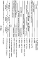
- Fig. 3 is a diagram showing a temporal sequence pattern of the analytical steps. More specifically, the five process steps in a solid-phase extraction are: (1) a solid phase extraction agent conditioning step to pass the organic solvent through a solid phase extraction agent, (2) a solid phase extraction agent equilibrating step to pass the water-based solvent through the solid phase extraction agent, (3) the step of retaining the analyte in the solid phase extraction agent by passing the sample through the solid phase extraction agent, (4) a washing step to pass water through the solid phase extraction agent, and (5) the step of passing the organic solvent through the solid phase extraction agent and eluting the analyte from the solid phase extraction agent.
- the solid phase extraction agent conditioning step to pass the organic solvent through a solid phase extraction agent is described below.
- the operation described below is controlled primarily by the control unit 29.
- One of the solid-phase cartridges 3 held in the cartridge storage unit 8, and one of the receiving trays 5 in the receiving tray storage unit 10 are mounted in an empty cartridge holder 4 and an empty receiving tray holder 6, respectively, by the cartridge transport arm 9 and the receiving tray transport arm 11, respectively.
- the organic solvent probe 14 then discharges methanol into the solid phase extraction cartridge 3 mounted in the cartridge holder 4. This step is conducted at position A shown in Fig. 2 .
- a plurality of solid phase extraction cartridges 3 are provided, each packed with an extraction agent for extraction modes of either reverse-phase, normal-phase, aion exchange, size exclusion, or mixed modes, which are s held in the cartridge storage unit 8.
- measuring parameters assay parameters prestored for various substances will be called up from the memory 106 via the interface 109 and an appropriate solid phase extraction cartridge 3 will be selected.
- the cartridge transport means 1 rotates.
- the cartridge holder 4 holding the solid phase extraction cartridge 3 to which methanol has been added moves to position B shown in Fig. 2 .
- the receiving tray transport means 2 positioned below the cartridge transport means also rotates coaxially and the cartridge holders 4 and the receiving tray holders 6 move maintaining respective relative positions.
- the pressure loader 7 positioned over positions B and D in Fig. 2 moves downward to the cartridge holder 4 at position B and applies an air pressure load to pass the methanol into the solid phase extraction cartridge 3 in which the solid phase is then conditioned. A waste liquid of the passed methanol will remain in the receiving tray 5.
- the cartridge transport means 1 rotates for the cartridge holder 4 holding the solid phase extraction cartridge 3 to reach position C shown in Fig. 2 .
- the cartridge holders 4 and the receiving tray holders 6 move maintaining the respective relative positions.
- the water-based solvent probe 13 then discharges water into the solid phase extraction cartridge 3 containing the conditioned solid phase extraction agent.
- the cartridge transport means 1 then rotates for the cartridge holder 4 holding the solid phase extraction cartridge 3 to reach position D.
- the cartridge holders 4 and the receiving tray holders 6 move maintaining the respective relative positions.
- the pressure loader 7 positioned over positions B and D, moves downward to the cartridge holders 4 at position D and applies an air pressure load to pass the water into the solid phase extraction cartridge 3 in which the solid phase extraction agent is then equilibrated. A waste liquid of the passed water will remain in the receiving tray 5.
- the cartridge transport means 1 rotates for the cartridge holder 4 holding the solid phase extraction cartridge 3 to reach position A.
- the cartridge holders 4 and the receiving tray holders 6 move maintaining the respective relative positions.
- the sample probe 12 moves to a position over the tip storage unit 17 and, at this position, one dispensing tip 18 is then mounted on the sample probe 12.
- the sample probe 12 with the mounted dispensing tip 18 moves to a position above one reagent container 16 from which the sample probe 12 then suctions the internal standard substance and discharges the suctioned substance into the solid phase extraction cartridge 3 containing the equilibrated solid phase extraction agent.
- the sample probe 12 moves to a position over the rack 20 that has been carried by the sample transport mechanism 19, then suctions the sample from the sample container 21, and discharges the sample into the solid phase extraction cartridge 3 set up in the cartridge transport means 1.
- the solution inside the cartridge 3 formed as a mixture of the sample and the internal standard substance is repeatedly suctioned and discharged a plurality of times for stirring.
- the sample probe 12 next moves to a position over a discarding port 22 and throws away the tip 18 that has been used.
- the cartridge transport means 1 then rotates for the cartridge holder 4 holding the solid phase extraction cartridge 3 to reach position B. At this time, similarly as above, the cartridge holders 4 and the receiving tray holders 6 move maintaining the respective relative positions.
- the passed sample solution will remain in the receiving tray 5.
- the cartridge transport means 1 rotates for the cartridge holder 4 holding the solid phase extraction cartridge 3 to reach position C.
- the cartridge holders 4 and the receiving tray holders 6 move maintaining the respective relative positions.
- the water-based solvent probe 13 discharges water into the solid phase extraction cartridge 3 holding the substance to be assayed (analyte).
- the cartridge transport means 1 then rotates for the cartridge holder 4 holding the solid phase extraction cartridge 3 to reach position D.
- the cartridge holders 4 and the receiving tray holders 6 move maintaining the respective relative positions.
- the pressure loader 7 positioned over positions B and D moves downward to the cartridge holder 4 at position D and applies an air pressure load to pass the water into the solid phase extraction cartridge 3 in which the solid phase extraction agent is then washed. The passed water will remain in the receiving tray 5.
- the cartridge transport means 1 rotates until the cartridge holder 4 holding the solid phase extraction cartridge 3 reaches position A. At this time, similarly as above, the cartridge holders 4 and the receiving tray holders 6 move maintaining the respective relative positions.
- the receiving tray transport arm 11 moves the receiving tray 5 with the waste liquid collected therein, to a position over a discarding port 22, and discards the tray 5 therefrom.
- the receiving tray transport arm 11 next moves to a position over the receiving tray storage unit 10 and mounts a new receiving tray 5 in the receiving tray holder 6.
- the organic solvent probe 14 next discharges methanol into the solid phase extraction cartridge 3 containing the above-washed solid phase extraction agent.
- the cartridge transport means 1 rotates until the cartridge holder 4 holding the solid phase extraction cartridge 3 reaches position B. At this time, similarly as above, the cartridge holders 4 and the receiving tray holders 6 move maintaining the respective relative positions.
- the eluted substance is collected in the receiving tray 5.
- an organic solvent is added to a solid phase extraction cartridge 3 at position A (1st substep).
- the organic solvent is passed through the solid phase extraction agent by a pressure load (2nd substep).
- a water-based solvent is added to the solid phase extraction cartridge 3 (3rd substep).
- the water-based solvent is passed through the solid phase extraction agent by a pressure load (4th substep).
- the transport means 1 rotates from position D to position A at which a reagent and a sample are then added to the solid phase extraction cartridge 3 (5th substep).
- position B the sample is retained in the solid phase extraction agent by a pressure load (6th substep).
- position C water-based solvent is added to the solid phase extraction cartridge 3 (7th substep).
- position D the water-based solvent is passed through the solid phase extraction agent by a pressure load (8th substep).
- the transport means 1 rotates from position D to position A at which organic solvent is then added to the solid phase extraction cartridge 3 (9th substep).
- the target substance in the solid phase extraction agent is eluted by a pressure load (10th substep) and then is collected in the receiving tray 5.
- the 10 process substeps are executed at positions A to D by the rotation of the cartridge holder 1 and receiving tray transport means 2 and the operation of the probes 12 to 14 and pressure loaders 7.
- the cartridge transport means 1 rotates until the cartridge holder 4 holding the solid phase extraction cartridge 3 has reached position C. At this time, similarly as above, the cartridge holders 4 and the receiving tray holders 6 move maintaining the respective relative positions.
- the analyte-containing eluate in the receiving tray 5 is suctioned by the eluate probe 23, and then is injected into the eluate injection port 25.
- the eluate injection port 25 is positioned on a flow path to which a solution is supplied from the pump 24.
- the FIA method where the sample is introduced into a flow path to which a solution is supplied from the pump 24, requires significantly shorter time compared to normal high-performance liquid chromatography/mass spectrometry (LC/MS) method.
- LC/MS liquid chromatography/mass spectrometry
- the solution is sent at a flow velocity of 100 microliters/min.
- an MRM (Multiple Reaction Monitoring) mode of a highly selective triple-quadrupole mass analyzer is used, where the analysis time is set to 2 minutes.
- the MRM mode is a method such that only a precursor signal is passed through using a quadrupole of a first stage, then the signal is fragmented in a next collision cell, and then only a product signal specific to the generated chemical compound is monitored using a quadrupole of a second stage.
- This method enables identification of a chemical compound with specific mass information relating to the compound.
- the mass analytical unit 27 can use any one of an ion trap mass analyzer, a time-of-flight mass analyzer, a quadrupole mass analyzer, and a Fourier transform mass analyzer, instead of a triple-quadrupole mass analyzer.
- the cartridge transport means 1 rotates for the cartridge holder 4 holding the solid phase extraction cartridge 3 to reach position D, and then a pressure loader 7 applies an air pressure load. After this, the cartridge transport means 1 further moves to make the cartridge holder 4 holding the solid phase extraction cartridge 3 reach position A.
- the cartridge transport arm 9 and the receiving tray transport arm 11 then move the solid phase extraction cartridge 3 and the receiving tray 5, respectively, to positions over respective discarding ports 22 and discard the solid phase extraction cartridge 3 and the receiving tray 5, respectively.
- the cartridge transport arm 9 and the receiving tray transport arm 11 move to a position over the cartridge storage unit 9 and the receiving tray storage unit 10, and mount a new solid phase extraction cartridge 3 and a new receiving tray 5, respectively, in the cartridge holder 4 and the receiving tray holder 6, respectively.
- the cartridge holders 4 are located in four places and the pressure loaders 7 in two places.
- the pressure loading positions B and D, and the sample and solvent adding positions A and C are located alternately on a circumference of the cartridge transport means 1, which is a rotating body.
- the solvent probes can be arranged such that the water-based solvent probe 13 is set for water-based solvent use only, and the organic solvent probe 14 is set for organic solvent use only. Furthermore, the probes 13 and 14 require no movement other than rotation or vertical movement for suctioning/discharging operations.
- each of the water-based solvent probe 13 and the organic solvent probe 14 includes a reservoir tank 205 for storage of a solvent, a pump 204 that supplies the solvent, a feed water valve 203, a syringe mechanism 202 that suctions an appropriate amount of solvent, and a probe 201 that discharges the solvent.
- the geometric size and the cost of the apparatus is reduced because of the simplified probe configuration, where the discharging position is fixed, requiring no movement for the probes 13, 14.
- the probes are further simplified because each probe is used for a dedicated solvent, rendering it unnecessary to exchange probe tips for undedicated solvents.
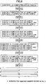
- the alternate layout of the solvent adding positions and pressure loaders in the first embodiment of the present invention enables four types of operation to be simultaneously processed in parallel and hence improves throughput. More specifically, as shown in Fig. 6 , in order to process a first sample, one solid phase extraction cartridge 3 and one receiving tray 5 are mounted, and then methanol is added, and then after the cartridge transport means 1 rotates them to position B, processing of a second sample can now be started.
- processing of a third sample can be started after the first sample has arrived at position C and the second sample at position B.
- processing of a third sample can be started after the first sample has arrived at position C and the second sample at position B.
- the cartridge transport means 1 starts rotating after all process substeps of each sample currently undergoing concurrent processing have been completed.
- the amount of solution to be used is minimized and costs are reduced.
- the volume of liquid solutions required during solid-phase extraction of one sample are 400 microliters (200 microliters x 2) of methanol, 400 microliters (200 microliters x 2) of water, 100 microliters of the sample, and 10 microliters of internal standard substance.
- Total solution consumption, inclusive of a quantity required for mass analysis, can be minimized to nearly 1 milli-liter. Cost reduction is therefore achievable and a waste liquid volume is also small. In addition, waste liquid processing costs can be reduced.
- the apparatus configuration in the first embodiment of the present invention includes the cartridge holders 4 in four places and the pressure loaders 7 in two places.
- the number of cartridge holders 4 and pressure loaders 7 becomes a factor in both dimensional reduction of the apparatus and the improvement of its throughput, both of which tend to conflict with each other.
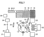
- the apparatus To assign priority to dimensional reduction, it is appropriate for the apparatus to include, for example, cartridge holders 4 in two places and a pressure loader 7 in one place, as shown in Fig. 7 .
- parallel processing is impossible, so that throughput decreases, and since reagent and solvent addition is limited to one place, the necessity arises to undertake preventive measures against movement interference between the probes and the arms during movement.
- apparatus configuration with, for example, the cartridge holders 4 in ten places and the pressure loaders 7 in five places, is appropriate.
- This configuration is shown in Fig. 8 .
- the successive solid-phase extraction substeps are completed while the cartridge transport means 1 rotates one full turn, the receiving tray storage units 10, the receiving tray transport arms 11, and the discarding ports 22 need to be arranged in a number of places.
- the water-based solvent probe 13 and the organic solvent probe 14 need to have a movable solvent-adding position. This increases an installation area of the apparatus and makes both the apparatus and individual parts complex in configuration.
- each cartridge holder 4 in the first embodiment of the present invention be modified into a multiple (in the illustrated example, triple) holder arrangement as shown in Fig. 9 .
- the holder arrangement shown in Fig. 9 is expected to improve throughput without increasing the apparatus installation area, and allow each of the water-based solvent probe 13 and the organic solvent probe 14 to have a fixed respective solvent-adding position.
- Fig. 9 shows a triple holder arrangement as an example, any arrangement with holders equal to or more than two holders (i.e., a double) may be adopted instead.
- extraction is repeated a plurality of times using solid phase extraction cartridges of different modes.
- a cartridge of a first stage is used for extraction in ion exchange mode and a cartridge of a second stage is used for in reverse-phase mode.
- purity improves and even for samples with differences between individuals, data reliability also improves.
- a substep progress pattern different from normal one is applied to such repetition of .
- the process completes after the cartridge transport means 2 rotates three full turns, whereas to complete this multiple extraction process, the cartridge transport means 2 rotates six full turns .
- the four cartridge holders 4 are positioned at an equal spacing in the cartridge transport means 1 adapted to carry the cartridge holders along the continuous track surface, and the two pressure loaders 7 are positioned over a pair of mutually corresponding cartridge holders 4 on the cartridge transport means 1.
- This layout enables the automatic analyzer to repeatedly execute the five substeps of solid-phase extraction , suppress expenditure cost associated with consumable materials, and conduct the successive solid-phase extraction substeps efficiently for separation and purification of multiple analytes.
- the above layout also makes the apparatus more compact and enhances throughput.
- circular cartridge transport means 1 and circular receiving tray transport means 2 in the above embodiment are constructed to rotate about the same rotational axis so that one cartridge holder 4 and one receiving tray holder 6 face each other in a vertical direction
- the circular cartridge transport means 1 and the circular receiving tray transport means 2 can also be constructed to rotate about rotational axes different from each other.
- the configuration may be such that the circular cartridge transport means 1 and the circular receiving tray transport means 2 are arranged in an offset condition relative to each other.
- the cartridge holder 4 and the receiving tray holder 6 in the receiving tray transport means 2 face each other in the vertical direction, while the holders 4 and 6 do not face each other at other positions, namely positions A, C, and D.
- a receiving tray 5 held by a receiving tray holder 6 in a receiving tray transport means 2 collects the extract of the analyte, which will be eluted from a solid phase extraction cartridge 3 in a cartridge holder 4, while a container other than a receiving tray 5 collects the solvent(s) used during solid phase extraction agent conditioning.
- design flexibility of the eluate removal probe 23 can be increased with an open space left over the receiving tray transport means 2.
Landscapes
- Chemical & Material Sciences (AREA)
- Biochemistry (AREA)
- General Physics & Mathematics (AREA)
- Health & Medical Sciences (AREA)
- Life Sciences & Earth Sciences (AREA)
- Analytical Chemistry (AREA)
- Pathology (AREA)
- General Health & Medical Sciences (AREA)
- Physics & Mathematics (AREA)
- Immunology (AREA)
- Chemical Kinetics & Catalysis (AREA)
- Sampling And Sample Adjustment (AREA)
- Automatic Analysis And Handling Materials Therefor (AREA)
- Other Investigation Or Analysis Of Materials By Electrical Means (AREA)
- Treatment Of Liquids With Adsorbents In General (AREA)
Claims (11)
- Vorverarbeitungsvorrichtung für biologische Proben, umfassend:Festphasen-Extraktionskartuschen (3), die jeweils dazu ausgelegt sind, spezifische Bestandteile einer biologischen Probe zu reinigen/konzentrieren;Kartuschen-Halterungen (4), die jeweils dazu ausgelegt sind, eine der Festphasen-Extraktionskartuschen (3) zu halten;eine Kartuschen-Transporteinrichtung (1), die dazu ausgelegt ist, die Kartuschen-Halterungen (4) entlang einer durchgängigen Spuroberfläche zu tragen;eine Probensonde (12), die dazu ausgelegt ist, die biologische Probe in die in einer der Kartuschen-Halterungen (4) gehaltenen Festphasen-Extraktionskartusche (3) auszulassen;eine erste Lösungsmittelsonde (13), die dazu ausgelegt ist, ein erstes Lösungsmittel in die in der Kartuschen-Halterung (4) gehaltene Festphasen-Extraktionskartusche (3) auszulassen;eine zweite Lösungsmittelsonde (14), die dazu ausgelegt ist, ein zweites Lösungsmittel in die in der Kartuschen-Halterung (4) gehaltene Festphasen-Extraktionskartusche (3) auszulassen;eine Druckladeeinrichtung (7), die dazu ausgelegt ist, eine Druckluftladung auf die in der Kartuschen-Halterung (4) gehaltene Festphasen-Extraktionskartusche (3) anzuwenden;Empfangstabletts (5), die jeweils dazu ausgelegt sind, einen aus den Festphasen-Extraktionskartuschen (3) eluierten Extrakt zu empfangen;Empfangstablett-Halterungen (6), die jeweils dazu ausgelegt sind, eines der Empfangstabletts (5) zu halten;eine Empfangstablett-Transporteinrichtung (2), die dazu ausgelegt ist, die Empfangstablett-Halterungen (6) zu tragen, wobei die Empfangstablett-Transporteinrichtung (2) unterhalb der Kartuschen-Transporteinrichtung (1) positioniert ist; undeine Steuereinheit (29), die dazu ausgelegt ist, den Betrieb der Kartuschen-Transporteinrichtung (1), der Probensonde (12), der Lösungsmittelsonden (13, 14), der Druckladeeinrichtung (7) und der Empfangstablett-Transporteinrichtung (2) zu steuern, wobei die Steuereinheit dazu ausgelegt ist, die Kartuschen-Transporteinrichtung und die Empfangstablett-Transporteinrichtung anzutreiben, während relative Positionen der Kartuschen-Halterungen und der Empfangstablett-Halterungen in einem gepaarten Zustand verbleiben;wobei die Steuereinheit (29) ferner dazu ausgelegt ist,die Kartuschen-Transporteinrichtung (1) rotieren zu lassen,die Festphasen-Extraktionskartusche (3), zu der die aus der Probensonde (12) ausgelassene Probe hinzugefügt wurde, zu einer benachbarten Position (B) der Druckladeeinrichtung zu bewegen,die Probe in einem Festphasenwirkstoff der Festphasen-Extraktionskartusche (3) durch Anwenden der Luftdruckladung darauf aus der Druckladeeinrichtung (7) verbleiben zu lassen,die Festphasen-Extraktionskartusche (3) zu einer benachbarten Position (C) einer ersten Lösungsmittelsonde zu bewegen,die erste Lösungsmittelsonde (13) ein vorgegebenes erstes Lösungsmittel in den Festphasenwirkstoff der Festphasen-Extraktionskartusche (3) auslassen zu lassen,die Festphasen-Extraktionskartusche (3) zu einer benachbarten Position (D) der Druckladeeinrichtung zu bewegen,das Waschen der Festphasen-Extraktionskartusche (3) durch Anwenden der Luftdruckladung darauf aus der Druckladeeinrichtung (7) zu bewirken,die Festphasen-Extraktionskartusche (3) zu der benachbarten Position (A) der zweiten Lösungsmittelsonde zu bewegen,die zweite Lösungsmittelsonde (14) ein vorgegebenes zweites Lösungsmittel in den Festphasenwirkstoff der Festphasen-Extraktionskartusche (3) auslassen zu lassen,die Festphasen-Extraktionskartusche (3) zu einer benachbarten Position (B) der Druckladeeinrichtung (7) zu bewegen unddas Eluieren der spezifischen Bestandteile durch Anwenden der Druckluftladung aus der Druckladeeinrichtung (7) auf die Festphasen-Extraktionskartusche (3) zu bewirken.
- Vorverarbeitungsvorrichtung für biologische Proben nach Anspruch 1, wobei:mindestens zwei der Kartuschen-Halterungen (4) mit einem gleichen Abstand in der Kartuschen-Transporteinrichtung (1) positioniert sind, die dazu ausgelegt ist, die Kartuschen-Halterungen (4) entlang der durchgängigen Spurenoberfläche zu tragen; undmindestens eine der Druckladeeinrichtungen (7) oberhalb der durchgängigen Spur, entlang der sich die Kartuschen-Halterungen (4) jeweils bewegen, positioniert ist.
- Vorverarbeitungsvorrichtung für biologische Proben nach Anspruch 2, wobei:die Empfangstablett-Transporteinrichtung (2) mindestens zwei Empfangstablett-Halterungen (6) enthält, die jeweils mit einer der Kartuschen-Halterungen (4) in einer vertikalen Richtung gepaart sind.
- Vorverarbeitungsvorrichtung für biologische Proben nach Anspruch 1, wobei:vier der Kartuschen-Halterungen (4) mit einem gleichen Abstand in der Kartuschen-Transporteinrichtung (1) positioniert sind, die dazu ausgelegt ist, die Kartuschen-Halterungen entlang der durchgängigen Spurenoberfläche zu tragen; undzwei der Druckladeeinrichtungen (7) oberhalb der durchgängigen Spur, entlang der sich die Kartuschen-Halterungen (4) bewegen, positioniert sind.
- Vorverarbeitungsvorrichtung für biologische Proben nach Anspruch 4, wobei:die Empfangstablett-Transporteinrichtung (2) vier Empfangstablett-Halterungen (6) enthält, die jeweils mit einer der Kartuschen-Halterungen (4) in einer vertikalen Richtung gepaart sind.
- Vorverarbeitungsvorrichtung für biologische Proben nach Anspruch 1, wobei:zehn der Kartuschen-Halterungen (4) mit einem gleichen Abstand in der Kartuschen-Transporteinrichtung (1) positioniert sind, die dazu ausgelegt ist, die Kartuschen-Halterungen entlang der durchgängigen Spurenoberfläche zu tragen; undfünf der Druckladeeinrichtungen (7) oberhalb der Kartuschen-Transporteinrichtung (1) positioniert sind.
- Vorverarbeitungsvorrichtung für biologische Proben nach Anspruch 6, wobei:die Empfangstablett-Transporteinrichtung (2) zehn Empfangstablett-Halterungen (6) enthält, die jeweils mit einer der Kartuschen-Halterungen (4) in einer vertikalen Richtung gepaart sind.
- Vorverarbeitungsvorrichtung für biologische Proben nach Anspruch 1, wobei:die Kartuschen-Halterungen (4) mit einem gleichen Abstand in der Kartuschen-Transporteinrichtung (1) positioniert sind, die dazu ausgelegt ist, die Kartuschen-Halterungen entlang der durchgängigen Spurenoberfläche zu tragen, sodass eine mehrfach verkettete Konfiguration gebildet wird, die mindestens zwei Festphasen-Extraktionskartuschen (3) enthält.
- Vorverarbeitungsvorrichtung für biologische Proben nach Anspruch 1, wobei:die Kartuschen-Transporteinrichtung (1) kreisförmig ist und eine Reihe von Verarbeitungsschritten nach Rotation der Einrichtung (1) durch mehrere volle Drehungen beendet wird.
- Vorverarbeitungsvorrichtung für biologische Proben nach Anspruch 1, wobei die Festphasen-Extraktionskartuschen (3) Festphasenextraktion mehrere Male wiederholen.
- Vorverarbeitungsvorrichtung für biologische Proben nach Anspruch 1, wobei die Festphasen-Extraktionskartuschen (3) verschiedener Modi während der Festphasenextraktion verwendet werden.
Applications Claiming Priority (2)
| Application Number | Priority Date | Filing Date | Title |
|---|---|---|---|
| JP2009151442 | 2009-06-25 | ||
| PCT/JP2010/060727 WO2010150842A1 (ja) | 2009-06-25 | 2010-06-24 | 前処理装置及びそれを備えた質量分析装置 |
Publications (3)
| Publication Number | Publication Date |
|---|---|
| EP2447697A1 EP2447697A1 (de) | 2012-05-02 |
| EP2447697A4 EP2447697A4 (de) | 2017-11-15 |
| EP2447697B1 true EP2447697B1 (de) | 2019-01-30 |
Family
ID=43386611
Family Applications (1)
| Application Number | Title | Priority Date | Filing Date |
|---|---|---|---|
| EP10792160.3A Not-in-force EP2447697B1 (de) | 2009-06-25 | 2010-06-24 | Vorverarbeitungsvorrichtung |
Country Status (5)
| Country | Link |
|---|---|
| US (1) | US9207152B2 (de) |
| EP (1) | EP2447697B1 (de) |
| JP (1) | JP5242787B2 (de) |
| CN (1) | CN102460107B (de) |
| WO (1) | WO2010150842A1 (de) |
Families Citing this family (22)
| Publication number | Priority date | Publication date | Assignee | Title |
|---|---|---|---|---|
| JP5519538B2 (ja) * | 2009-01-29 | 2014-06-11 | 株式会社日立ハイテクノロジーズ | サンプルの前処理装置、及びそれを備えた質量分析装置 |
| JP5242532B2 (ja) * | 2009-10-16 | 2013-07-24 | 株式会社日立ハイテクノロジーズ | 検査装置 |
| JP5639959B2 (ja) * | 2011-06-06 | 2014-12-10 | 株式会社日立ハイテクノロジーズ | 前処理装置及びそれを用いた自動分析装置 |
| FI20115785A0 (fi) * | 2011-08-08 | 2011-08-08 | Thermo Fisher Scientific Oy | Menetelmä ja laite automaattiseen analyysiin |
| CN104520717B (zh) * | 2012-07-25 | 2015-11-25 | 株式会社日立高新技术 | 分析装置 |
| DE102012016830B4 (de) * | 2012-08-24 | 2021-08-26 | Bruker Daltonics GmbH & Co. KG | Präparationsvorrichtung für massenspektrometrische Proben |
| CN104749159A (zh) * | 2013-12-30 | 2015-07-01 | 同方威视技术股份有限公司 | 农药残留检测方法 |
| EP3165916B1 (de) * | 2014-07-02 | 2023-08-23 | Shimadzu Corporation | Vorverarbeitungsvorrichtung |
| JP6264465B2 (ja) * | 2014-09-02 | 2018-01-24 | 株式会社島津製作所 | 前処理装置及びこれを備えた分析システム |
| EP3190407B1 (de) * | 2014-09-02 | 2021-10-27 | Shimadzu Corporation | Vorverarbeitungsvorrichtung und analysesystem damit |
| KR101700624B1 (ko) * | 2014-12-24 | 2017-02-14 | 나노바이오시스 주식회사 | 핵산 추출 장치 및 그 동작 방법 |
| KR20180036644A (ko) * | 2015-03-13 | 2018-04-09 | 더 클리블랜드 클리닉 파운데이션 | 멸균 및/또는 정제된 유체 및/또는 용액 전달 시스템 |
| CN105067401B (zh) * | 2015-07-24 | 2017-12-19 | 宁波大学 | 一种快速回收透明土中孔隙溶液的装置及操作方法 |
| JP6798446B2 (ja) * | 2017-08-03 | 2020-12-09 | 株式会社島津製作所 | 前処理装置及びその前処理装置を備えた分析システム |
| CN109376816B (zh) * | 2018-09-11 | 2022-04-01 | 广州金域医学检验中心有限公司 | 一种病理切片质量监控方法及其装置 |
| JP7095796B2 (ja) * | 2019-02-19 | 2022-07-05 | 株式会社島津製作所 | 質量分析装置 |
| CN110197786B (zh) * | 2019-05-10 | 2025-04-11 | 江苏瑞明生物科技有限公司 | 全自动单细胞质谱检测进样器 |
| CN111157325A (zh) * | 2020-01-07 | 2020-05-15 | 沈丹 | 一种用于生态环境检测的有机物提取装置 |
| CN113655154B (zh) * | 2020-05-12 | 2023-07-14 | 国家烟草质量监督检验中心 | 一种适用于烟气中水分测定的原位萃取仪及测试方法 |
| CN111855344B (zh) * | 2020-06-29 | 2023-09-15 | 河南广电计量检测有限公司 | 一种用于农药残留检测的前处理装置 |
| CN111948277B (zh) * | 2020-07-03 | 2021-08-10 | 中国地质大学(武汉) | 一种多功能连续式在线气体制备和导入装置 |
| CN113030341B (zh) * | 2021-04-14 | 2022-09-16 | 南芯芯仪(广州)制造有限公司 | 制备液相串联质谱样本的系统 |
Family Cites Families (11)
| Publication number | Priority date | Publication date | Assignee | Title |
|---|---|---|---|---|
| JPH01174968A (ja) | 1987-12-29 | 1989-07-11 | Shimadzu Corp | 自動化学分析装置 |
| US5585068A (en) * | 1990-02-20 | 1996-12-17 | Biochemical Diagnostics, Inc. | Apparatus for automatically separating a compound from a plurality of discrete liquid specimens |
| JP2970114B2 (ja) * | 1991-09-20 | 1999-11-02 | 株式会社日立製作所 | 自動分析装置 |
| US5660727A (en) * | 1994-06-14 | 1997-08-26 | Dionex Corporation | Automated analyte supercritical fluid extraction apparatus |
| JPH11201953A (ja) * | 1998-01-14 | 1999-07-30 | Toyota Central Res & Dev Lab Inc | 固相抽出装置用カートリッジ |
| JP3675681B2 (ja) | 1999-09-02 | 2005-07-27 | 株式会社サクション瓦斯機関製作所 | 容器移動装置およびクロマトグラフ装置 |
| JP2002202316A (ja) * | 2000-11-01 | 2002-07-19 | Jeol Ltd | 分析システムおよび分析方法 |
| JP2004093194A (ja) * | 2002-08-29 | 2004-03-25 | Ngk Insulators Ltd | カラム処理装置 |
| JP2006007081A (ja) | 2004-06-25 | 2006-01-12 | Hitachi Koki Co Ltd | 自動固相抽出装置 |
| CN102565438B (zh) * | 2005-04-01 | 2014-05-07 | 三菱化学美迪恩斯株式会社 | 反应杯 |
| JP5530609B2 (ja) * | 2008-09-05 | 2014-06-25 | 株式会社日立ハイテクノロジーズ | 前処理装置及びそれを備えた質量分析装置 |
-
2010
- 2010-06-24 EP EP10792160.3A patent/EP2447697B1/de not_active Not-in-force
- 2010-06-24 JP JP2011519933A patent/JP5242787B2/ja not_active Expired - Fee Related
- 2010-06-24 US US13/377,154 patent/US9207152B2/en not_active Expired - Fee Related
- 2010-06-24 WO PCT/JP2010/060727 patent/WO2010150842A1/ja not_active Ceased
- 2010-06-24 CN CN201080026060.0A patent/CN102460107B/zh not_active Expired - Fee Related
Non-Patent Citations (1)
| Title |
|---|
| None * |
Also Published As
| Publication number | Publication date |
|---|---|
| JPWO2010150842A1 (ja) | 2012-12-10 |
| US20120079875A1 (en) | 2012-04-05 |
| EP2447697A1 (de) | 2012-05-02 |
| US9207152B2 (en) | 2015-12-08 |
| CN102460107B (zh) | 2014-10-08 |
| EP2447697A4 (de) | 2017-11-15 |
| WO2010150842A1 (ja) | 2010-12-29 |
| CN102460107A (zh) | 2012-05-16 |
| JP5242787B2 (ja) | 2013-07-24 |
Similar Documents
| Publication | Publication Date | Title |
|---|---|---|
| US9207152B2 (en) | Pretreatment apparatus and mass analyzing apparatus equipped with the same | |
| US8319179B2 (en) | Sample pretreatment apparatus and mass spectrometer provided with the same | |
| EP2490019B1 (de) | Untersuchungsvorrichtung und untersuchungsverfahren | |
| US8926903B2 (en) | Pretreatment apparatus and mass spectrometer equipped with the same apparatus | |
| JP6955038B2 (ja) | 自動臨床診断システムおよび方法 | |
| EP2633327B1 (de) | Systemanordnung für ein automatisiertes system zur probenvorbereitung und -analyse | |
| US10184948B2 (en) | Automated analyzer | |
| EP2466289B1 (de) | Probenverarbeitungssystem | |
| US3814582A (en) | Automated chemical analyser system | |
| WO2010087109A1 (ja) | 生体サンプルの前処理装置、及びそれを備えた質量分析装置 | |
| EP3961223B1 (de) | Automatische analysevorrichtung | |
| KR20060058682A (ko) | 모듈형 시약 전달 수단을 이용한 자동 임상 분석기의 용량증가 방법 | |
| JP2020038205A5 (de) | ||
| WO2005008217A9 (en) | Method for increasing capacity in an automatic clinical analyzer by using modular reagent delivery means | |
| JP6047385B2 (ja) | 自動分析装置 | |
| JP7247286B2 (ja) | 試料注入器 | |
| JPH02231570A (ja) | 自動化学分析装置 |
Legal Events
| Date | Code | Title | Description |
|---|---|---|---|
| PUAI | Public reference made under article 153(3) epc to a published international application that has entered the european phase |
Free format text: ORIGINAL CODE: 0009012 |
|
| 17P | Request for examination filed |
Effective date: 20120119 |
|
| AK | Designated contracting states |
Kind code of ref document: A1 Designated state(s): AL AT BE BG CH CY CZ DE DK EE ES FI FR GB GR HR HU IE IS IT LI LT LU LV MC MK MT NL NO PL PT RO SE SI SK SM TR |
|
| DAX | Request for extension of the european patent (deleted) | ||
| RA4 | Supplementary search report drawn up and despatched (corrected) |
Effective date: 20171016 |
|
| RIC1 | Information provided on ipc code assigned before grant |
Ipc: G01N 1/02 20060101ALI20171010BHEP Ipc: G01N 35/02 20060101ALI20171010BHEP Ipc: G01N 30/06 20060101ALI20171010BHEP Ipc: H01J 49/00 20060101ALI20171010BHEP Ipc: G01N 30/00 20060101ALI20171010BHEP Ipc: G01N 1/40 20060101ALI20171010BHEP Ipc: G01N 27/62 20060101ALI20171010BHEP Ipc: G01N 1/10 20060101AFI20171010BHEP Ipc: G01N 30/02 20060101ALI20171010BHEP Ipc: G01N 30/88 20060101ALI20171010BHEP Ipc: G01N 30/32 20060101ALI20171010BHEP Ipc: G01N 30/26 20060101ALI20171010BHEP Ipc: G01N 30/60 20060101ALI20171010BHEP |
|
| STAA | Information on the status of an ep patent application or granted ep patent |
Free format text: STATUS: EXAMINATION IS IN PROGRESS |
|
| 17Q | First examination report despatched |
Effective date: 20180515 |
|
| GRAP | Despatch of communication of intention to grant a patent |
Free format text: ORIGINAL CODE: EPIDOSNIGR1 |
|
| STAA | Information on the status of an ep patent application or granted ep patent |
Free format text: STATUS: GRANT OF PATENT IS INTENDED |
|
| INTG | Intention to grant announced |
Effective date: 20181004 |
|
| GRAS | Grant fee paid |
Free format text: ORIGINAL CODE: EPIDOSNIGR3 |
|
| GRAA | (expected) grant |
Free format text: ORIGINAL CODE: 0009210 |
|
| STAA | Information on the status of an ep patent application or granted ep patent |
Free format text: STATUS: THE PATENT HAS BEEN GRANTED |
|
| AK | Designated contracting states |
Kind code of ref document: B1 Designated state(s): AL AT BE BG CH CY CZ DE DK EE ES FI FR GB GR HR HU IE IS IT LI LT LU LV MC MK MT NL NO PL PT RO SE SI SK SM TR |
|
| REG | Reference to a national code |
Ref country code: GB Ref legal event code: FG4D |
|
| REG | Reference to a national code |
Ref country code: CH Ref legal event code: EP |
|
| REG | Reference to a national code |
Ref country code: AT Ref legal event code: REF Ref document number: 1093677 Country of ref document: AT Kind code of ref document: T Effective date: 20190215 |
|
| REG | Reference to a national code |
Ref country code: IE Ref legal event code: FG4D |
|
| REG | Reference to a national code |
Ref country code: DE Ref legal event code: R096 Ref document number: 602010056870 Country of ref document: DE |
|
| REG | Reference to a national code |
Ref country code: LT Ref legal event code: MG4D |
|
| REG | Reference to a national code |
Ref country code: NL Ref legal event code: MP Effective date: 20190130 |
|
| PG25 | Lapsed in a contracting state [announced via postgrant information from national office to epo] |
Ref country code: FI Free format text: LAPSE BECAUSE OF FAILURE TO SUBMIT A TRANSLATION OF THE DESCRIPTION OR TO PAY THE FEE WITHIN THE PRESCRIBED TIME-LIMIT Effective date: 20190130 Ref country code: NL Free format text: LAPSE BECAUSE OF FAILURE TO SUBMIT A TRANSLATION OF THE DESCRIPTION OR TO PAY THE FEE WITHIN THE PRESCRIBED TIME-LIMIT Effective date: 20190130 Ref country code: SE Free format text: LAPSE BECAUSE OF FAILURE TO SUBMIT A TRANSLATION OF THE DESCRIPTION OR TO PAY THE FEE WITHIN THE PRESCRIBED TIME-LIMIT Effective date: 20190130 Ref country code: ES Free format text: LAPSE BECAUSE OF FAILURE TO SUBMIT A TRANSLATION OF THE DESCRIPTION OR TO PAY THE FEE WITHIN THE PRESCRIBED TIME-LIMIT Effective date: 20190130 Ref country code: LT Free format text: LAPSE BECAUSE OF FAILURE TO SUBMIT A TRANSLATION OF THE DESCRIPTION OR TO PAY THE FEE WITHIN THE PRESCRIBED TIME-LIMIT Effective date: 20190130 Ref country code: NO Free format text: LAPSE BECAUSE OF FAILURE TO SUBMIT A TRANSLATION OF THE DESCRIPTION OR TO PAY THE FEE WITHIN THE PRESCRIBED TIME-LIMIT Effective date: 20190430 Ref country code: PT Free format text: LAPSE BECAUSE OF FAILURE TO SUBMIT A TRANSLATION OF THE DESCRIPTION OR TO PAY THE FEE WITHIN THE PRESCRIBED TIME-LIMIT Effective date: 20190530 Ref country code: PL Free format text: LAPSE BECAUSE OF FAILURE TO SUBMIT A TRANSLATION OF THE DESCRIPTION OR TO PAY THE FEE WITHIN THE PRESCRIBED TIME-LIMIT Effective date: 20190130 |
|
| REG | Reference to a national code |
Ref country code: AT Ref legal event code: MK05 Ref document number: 1093677 Country of ref document: AT Kind code of ref document: T Effective date: 20190130 |
|
| PG25 | Lapsed in a contracting state [announced via postgrant information from national office to epo] |
Ref country code: HR Free format text: LAPSE BECAUSE OF FAILURE TO SUBMIT A TRANSLATION OF THE DESCRIPTION OR TO PAY THE FEE WITHIN THE PRESCRIBED TIME-LIMIT Effective date: 20190130 Ref country code: GR Free format text: LAPSE BECAUSE OF FAILURE TO SUBMIT A TRANSLATION OF THE DESCRIPTION OR TO PAY THE FEE WITHIN THE PRESCRIBED TIME-LIMIT Effective date: 20190501 Ref country code: LV Free format text: LAPSE BECAUSE OF FAILURE TO SUBMIT A TRANSLATION OF THE DESCRIPTION OR TO PAY THE FEE WITHIN THE PRESCRIBED TIME-LIMIT Effective date: 20190130 Ref country code: IS Free format text: LAPSE BECAUSE OF FAILURE TO SUBMIT A TRANSLATION OF THE DESCRIPTION OR TO PAY THE FEE WITHIN THE PRESCRIBED TIME-LIMIT Effective date: 20190530 Ref country code: BG Free format text: LAPSE BECAUSE OF FAILURE TO SUBMIT A TRANSLATION OF THE DESCRIPTION OR TO PAY THE FEE WITHIN THE PRESCRIBED TIME-LIMIT Effective date: 20190430 |
|
| PG25 | Lapsed in a contracting state [announced via postgrant information from national office to epo] |
Ref country code: EE Free format text: LAPSE BECAUSE OF FAILURE TO SUBMIT A TRANSLATION OF THE DESCRIPTION OR TO PAY THE FEE WITHIN THE PRESCRIBED TIME-LIMIT Effective date: 20190130 Ref country code: RO Free format text: LAPSE BECAUSE OF FAILURE TO SUBMIT A TRANSLATION OF THE DESCRIPTION OR TO PAY THE FEE WITHIN THE PRESCRIBED TIME-LIMIT Effective date: 20190130 Ref country code: CZ Free format text: LAPSE BECAUSE OF FAILURE TO SUBMIT A TRANSLATION OF THE DESCRIPTION OR TO PAY THE FEE WITHIN THE PRESCRIBED TIME-LIMIT Effective date: 20190130 Ref country code: AL Free format text: LAPSE BECAUSE OF FAILURE TO SUBMIT A TRANSLATION OF THE DESCRIPTION OR TO PAY THE FEE WITHIN THE PRESCRIBED TIME-LIMIT Effective date: 20190130 Ref country code: IT Free format text: LAPSE BECAUSE OF FAILURE TO SUBMIT A TRANSLATION OF THE DESCRIPTION OR TO PAY THE FEE WITHIN THE PRESCRIBED TIME-LIMIT Effective date: 20190130 Ref country code: DK Free format text: LAPSE BECAUSE OF FAILURE TO SUBMIT A TRANSLATION OF THE DESCRIPTION OR TO PAY THE FEE WITHIN THE PRESCRIBED TIME-LIMIT Effective date: 20190130 Ref country code: SK Free format text: LAPSE BECAUSE OF FAILURE TO SUBMIT A TRANSLATION OF THE DESCRIPTION OR TO PAY THE FEE WITHIN THE PRESCRIBED TIME-LIMIT Effective date: 20190130 |
|
| REG | Reference to a national code |
Ref country code: DE Ref legal event code: R097 Ref document number: 602010056870 Country of ref document: DE |
|
| PG25 | Lapsed in a contracting state [announced via postgrant information from national office to epo] |
Ref country code: SM Free format text: LAPSE BECAUSE OF FAILURE TO SUBMIT A TRANSLATION OF THE DESCRIPTION OR TO PAY THE FEE WITHIN THE PRESCRIBED TIME-LIMIT Effective date: 20190130 |
|
| PLBE | No opposition filed within time limit |
Free format text: ORIGINAL CODE: 0009261 |
|
| STAA | Information on the status of an ep patent application or granted ep patent |
Free format text: STATUS: NO OPPOSITION FILED WITHIN TIME LIMIT |
|
| PG25 | Lapsed in a contracting state [announced via postgrant information from national office to epo] |
Ref country code: AT Free format text: LAPSE BECAUSE OF FAILURE TO SUBMIT A TRANSLATION OF THE DESCRIPTION OR TO PAY THE FEE WITHIN THE PRESCRIBED TIME-LIMIT Effective date: 20190130 |
|
| 26N | No opposition filed |
Effective date: 20191031 |
|
| PG25 | Lapsed in a contracting state [announced via postgrant information from national office to epo] |
Ref country code: MC Free format text: LAPSE BECAUSE OF FAILURE TO SUBMIT A TRANSLATION OF THE DESCRIPTION OR TO PAY THE FEE WITHIN THE PRESCRIBED TIME-LIMIT Effective date: 20190130 |
|
| REG | Reference to a national code |
Ref country code: CH Ref legal event code: PL |
|
| GBPC | Gb: european patent ceased through non-payment of renewal fee |
Effective date: 20190624 |
|
| PG25 | Lapsed in a contracting state [announced via postgrant information from national office to epo] |
Ref country code: SI Free format text: LAPSE BECAUSE OF FAILURE TO SUBMIT A TRANSLATION OF THE DESCRIPTION OR TO PAY THE FEE WITHIN THE PRESCRIBED TIME-LIMIT Effective date: 20190130 |
|
| REG | Reference to a national code |
Ref country code: BE Ref legal event code: MM Effective date: 20190630 |
|
| PG25 | Lapsed in a contracting state [announced via postgrant information from national office to epo] |
Ref country code: TR Free format text: LAPSE BECAUSE OF FAILURE TO SUBMIT A TRANSLATION OF THE DESCRIPTION OR TO PAY THE FEE WITHIN THE PRESCRIBED TIME-LIMIT Effective date: 20190130 |
|
| PG25 | Lapsed in a contracting state [announced via postgrant information from national office to epo] |
Ref country code: GB Free format text: LAPSE BECAUSE OF NON-PAYMENT OF DUE FEES Effective date: 20190624 Ref country code: IE Free format text: LAPSE BECAUSE OF NON-PAYMENT OF DUE FEES Effective date: 20190624 |
|
| PG25 | Lapsed in a contracting state [announced via postgrant information from national office to epo] |
Ref country code: LI Free format text: LAPSE BECAUSE OF NON-PAYMENT OF DUE FEES Effective date: 20190630 Ref country code: LU Free format text: LAPSE BECAUSE OF NON-PAYMENT OF DUE FEES Effective date: 20190624 Ref country code: BE Free format text: LAPSE BECAUSE OF NON-PAYMENT OF DUE FEES Effective date: 20190630 Ref country code: CH Free format text: LAPSE BECAUSE OF NON-PAYMENT OF DUE FEES Effective date: 20190630 |
|
| REG | Reference to a national code |
Ref country code: DE Ref legal event code: R082 Ref document number: 602010056870 Country of ref document: DE Representative=s name: STREHL SCHUEBEL-HOPF & PARTNER MBB PATENTANWAE, DE Ref country code: DE Ref legal event code: R081 Ref document number: 602010056870 Country of ref document: DE Owner name: HITACHI HIGH-TECH CORPORATION, JP Free format text: FORMER OWNER: HITACHI HIGH-TECHNOLOGIES CORPORATION, TOKYO, JP |
|
| PG25 | Lapsed in a contracting state [announced via postgrant information from national office to epo] |
Ref country code: CY Free format text: LAPSE BECAUSE OF FAILURE TO SUBMIT A TRANSLATION OF THE DESCRIPTION OR TO PAY THE FEE WITHIN THE PRESCRIBED TIME-LIMIT Effective date: 20190130 |
|
| PG25 | Lapsed in a contracting state [announced via postgrant information from national office to epo] |
Ref country code: HU Free format text: LAPSE BECAUSE OF FAILURE TO SUBMIT A TRANSLATION OF THE DESCRIPTION OR TO PAY THE FEE WITHIN THE PRESCRIBED TIME-LIMIT; INVALID AB INITIO Effective date: 20100624 Ref country code: MT Free format text: LAPSE BECAUSE OF FAILURE TO SUBMIT A TRANSLATION OF THE DESCRIPTION OR TO PAY THE FEE WITHIN THE PRESCRIBED TIME-LIMIT Effective date: 20190130 |
|
| PGFP | Annual fee paid to national office [announced via postgrant information from national office to epo] |
Ref country code: DE Payment date: 20210525 Year of fee payment: 12 Ref country code: FR Payment date: 20210513 Year of fee payment: 12 |
|
| PG25 | Lapsed in a contracting state [announced via postgrant information from national office to epo] |
Ref country code: MK Free format text: LAPSE BECAUSE OF FAILURE TO SUBMIT A TRANSLATION OF THE DESCRIPTION OR TO PAY THE FEE WITHIN THE PRESCRIBED TIME-LIMIT Effective date: 20190130 |
|
| REG | Reference to a national code |
Ref country code: DE Ref legal event code: R119 Ref document number: 602010056870 Country of ref document: DE |
|
| PG25 | Lapsed in a contracting state [announced via postgrant information from national office to epo] |
Ref country code: FR Free format text: LAPSE BECAUSE OF NON-PAYMENT OF DUE FEES Effective date: 20220630 |
|
| PG25 | Lapsed in a contracting state [announced via postgrant information from national office to epo] |
Ref country code: DE Free format text: LAPSE BECAUSE OF NON-PAYMENT OF DUE FEES Effective date: 20230103 |