EP2447130A1 - Türschalter für schienenfahrzeug, und türöffnungs- bzw. -schliessvorrichtung zur verwendung in einem schienenfahrzeug und mit diesem türschalter - Google Patents
Türschalter für schienenfahrzeug, und türöffnungs- bzw. -schliessvorrichtung zur verwendung in einem schienenfahrzeug und mit diesem türschalter Download PDFInfo
- Publication number
- EP2447130A1 EP2447130A1 EP10791941A EP10791941A EP2447130A1 EP 2447130 A1 EP2447130 A1 EP 2447130A1 EP 10791941 A EP10791941 A EP 10791941A EP 10791941 A EP10791941 A EP 10791941A EP 2447130 A1 EP2447130 A1 EP 2447130A1
- Authority
- EP
- European Patent Office
- Prior art keywords
- passive component
- doors
- door
- component
- rod
- Prior art date
- Legal status (The legal status is an assumption and is not a legal conclusion. Google has not performed a legal analysis and makes no representation as to the accuracy of the status listed.)
- Granted
Links
- 238000001514 detection method Methods 0.000 claims abstract description 105
- 230000004048 modification Effects 0.000 description 25
- 238000012986 modification Methods 0.000 description 25
- 230000000717 retained effect Effects 0.000 description 6
- 230000000694 effects Effects 0.000 description 5
- 239000002184 metal Substances 0.000 description 3
- 230000035945 sensitivity Effects 0.000 description 2
- 239000006096 absorbing agent Substances 0.000 description 1
- 230000002411 adverse Effects 0.000 description 1
- 239000012530 fluid Substances 0.000 description 1
- 230000006870 function Effects 0.000 description 1
- 238000012423 maintenance Methods 0.000 description 1
- 239000000463 material Substances 0.000 description 1
- 230000035939 shock Effects 0.000 description 1
Images


Classifications
-
- B—PERFORMING OPERATIONS; TRANSPORTING
- B61—RAILWAYS
- B61D—BODY DETAILS OR KINDS OF RAILWAY VEHICLES
- B61D19/00—Door arrangements specially adapted for rail vehicles
- B61D19/02—Door arrangements specially adapted for rail vehicles for carriages
-
- E—FIXED CONSTRUCTIONS
- E05—LOCKS; KEYS; WINDOW OR DOOR FITTINGS; SAFES
- E05F—DEVICES FOR MOVING WINGS INTO OPEN OR CLOSED POSITION; CHECKS FOR WINGS; WING FITTINGS NOT OTHERWISE PROVIDED FOR, CONCERNED WITH THE FUNCTIONING OF THE WING
- E05F15/00—Power-operated mechanisms for wings
-
- E—FIXED CONSTRUCTIONS
- E05—LOCKS; KEYS; WINDOW OR DOOR FITTINGS; SAFES
- E05Y—INDEXING SCHEME ASSOCIATED WITH SUBCLASSES E05D AND E05F, RELATING TO CONSTRUCTION ELEMENTS, ELECTRIC CONTROL, POWER SUPPLY, POWER SIGNAL OR TRANSMISSION, USER INTERFACES, MOUNTING OR COUPLING, DETAILS, ACCESSORIES, AUXILIARY OPERATIONS NOT OTHERWISE PROVIDED FOR, APPLICATION THEREOF
- E05Y2400/00—Electronic control; Electrical power; Power supply; Power or signal transmission; User interfaces
- E05Y2400/10—Electronic control
- E05Y2400/32—Position control, detection or monitoring
- E05Y2400/35—Position control, detection or monitoring related to specific positions
- E05Y2400/354—End positions
-
- E—FIXED CONSTRUCTIONS
- E05—LOCKS; KEYS; WINDOW OR DOOR FITTINGS; SAFES
- E05Y—INDEXING SCHEME ASSOCIATED WITH SUBCLASSES E05D AND E05F, RELATING TO CONSTRUCTION ELEMENTS, ELECTRIC CONTROL, POWER SUPPLY, POWER SIGNAL OR TRANSMISSION, USER INTERFACES, MOUNTING OR COUPLING, DETAILS, ACCESSORIES, AUXILIARY OPERATIONS NOT OTHERWISE PROVIDED FOR, APPLICATION THEREOF
- E05Y2400/00—Electronic control; Electrical power; Power supply; Power or signal transmission; User interfaces
- E05Y2400/10—Electronic control
- E05Y2400/50—Fault detection
- E05Y2400/51—Fault detection of position, of back drive
-
- E—FIXED CONSTRUCTIONS
- E05—LOCKS; KEYS; WINDOW OR DOOR FITTINGS; SAFES
- E05Y—INDEXING SCHEME ASSOCIATED WITH SUBCLASSES E05D AND E05F, RELATING TO CONSTRUCTION ELEMENTS, ELECTRIC CONTROL, POWER SUPPLY, POWER SIGNAL OR TRANSMISSION, USER INTERFACES, MOUNTING OR COUPLING, DETAILS, ACCESSORIES, AUXILIARY OPERATIONS NOT OTHERWISE PROVIDED FOR, APPLICATION THEREOF
- E05Y2900/00—Application of doors, windows, wings or fittings thereof
- E05Y2900/50—Application of doors, windows, wings or fittings thereof for vehicles
- E05Y2900/51—Application of doors, windows, wings or fittings thereof for vehicles for railway cars or mass transit vehicles
Definitions
- the present invention relates to a door opening/closing device for a railroad vehicle, and a door switch for a railroad vehicle, which detects that double doors have been closed.
- the door opening/closing device above is arranged to operate so that the double doors are opened and closed by mechanically interlocking with each other. Therefore, when one of the double doors is at the full-closed position, the other door is usually at the full-closed position, too. It is therefore possible to determine, by using the door closing switch above, whether both of the double doors are at the full-closed positions.
- a door switch for a railroad vehicle which certainly detects whether the double doors are at the full-closed positions even if there is a failure in the mechanism causing the doors to interlock with each other, has been on demand.
- a conceivable solution to the problem above is to provide two door closing switches each arranged as above, to correspond to the respective doors.
- This approach requires another switch, and the increase in the number of electrical components may result in the increase in the failure rate of the entire system. Furthermore, the increase in the number of components results in the increase in the cost.
- Another conceivable solution to the problem above is to attach the door closing switch to one door instead of fixing it to the vehicle body, and the switch is operated by the other door. In this approach, however, since the wires of the door closing switch are moved for a long distance to the same degree as the opening/closing stroke, when the door is opened or closed, the wires are susceptible to disconnection and hence it is difficult to certainly detect whether the double doors are at the full-closed positions. Furthermore, since the wires are required to have high durability, cost increase is expected.
- An object of the present invention in consideration of the problem above is to provide a door switch for a railroad vehicle, which can reliably detect whether double doors are at full-closed positions without needing another switch, and to provide a door opening/closing device for a railroad vehicle equipped with the door switch.
- a door switch for a railroad vehicle is installed in the railroad vehicle having double doors and includes: a first passive component which is arranged to be movable relative to a vehicle main body and is biased when one of the doors moves toward a full-closed position; a second passive component which is arranged to be movable relative to the vehicle main body and the first passive component and is biased when the other one of the doors is moves toward a full-closed position; a detection unit which outputs a detection signal when the first passive component and the second passive component take predetermined relative positions; a biasing member which biases the first passive component and the second passive component to prevent the first passive component and the second passive component from taking the predetermined relative positions; the predetermined relative positions being relative positions of the first passive component and the second passive component when the first passive component and the second passive component are biased by the double doors against a biasing force of the biasing member and both of the double doors eventually reach the full-closed positions.
- the biasing force of the biasing member prevents the first passive component and the second passive component from taking the predetermined relative positions, and hence no detection signal is output from the detection unit. This makes it possible to certainly detect whether the double doors are at the full-closed positions, without needing another switch.
- the first passive component and the second passive component are arranged to be movable in opening/closing directions of the doors, with respect to the vehicle main body.
- the door switch further includes: a limit switch including the first passive component, the second passive component movably support the first passive component, an elastic component provided between the first passive component and the second passive component and functioning as the biasing component, and the detection unit which outputs the detection signal when the first passive component moves for a predetermined distance with respect to the second passive component against an elastic force of the elastic component, the limit switch being arranged to be movable with respect to the vehicle main body in directions in parallel to a direction of movement of the first passive component with respect to the second passive component, and as one of the doors is biased by the first passive component and the other one of the doors is biased by the second passive component, the first passive component moving with respect to the second passive component against the elastic force of the elastic component, and a moving distance of the first passive component with respect to the second passive component being equal to the predetermined distance when both of the doors reach the full-closed positions.
- a limit switch including the first passive component, the second passive component movably support the first passive component, an elastic component provided between the first passive component and the second passive
- the first passive component and the second passive component are rotatable about a rotation axis which is fixed to the vehicle main body, and the rotation axis extends in directions orthogonal to the flat plate-shaped doors.
- the detection unit outputs the detection signal when the first detection unit attached to the first passive component and the second detection unit attached to the second passive component take a predetermined positional relationship, the first detection unit is provided at a position further from the rotation axis of the first passive component than a position at which the first passive component is biased by said one of the doors, and the second detection unit is provided at a position further from the rotation axis of the second passive component than a position at which the second passive component is biased by the other one of the doors.
- the degree of change in the relative positions of the first detection unit and the second detection unit is great.
- a door opening/closing device for a railroad vehicle which is used for opening and closing double doors, includes: the door switch according to any one of claims 1 to 5; and a control unit which receives the detection signal output from the detection unit, the control unit driving a locking unit for locking the doors or controlling a drive output for opening and closing the doors, based on the detection signal.
- this arrangement it is possible to certainly detect whether the double doors are at the full-closed positions, and to utilize the detection signal output from the detection unit for locking the doors or controlling the operation of the doors. This makes it possible to prevent the doors from being erroneously locked when at least one of the doors has not reached the full-closed position. Furthermore, it is possible to prevent the driving output for opening and closing the doors from being controlled when at least one of the doors has not reached the full-closed position.
- the door switch for the railroad vehicle of the present invention and the door opening/closing device for the railroad vehicle equipped with the door switch make it possible to certainly detect whether the double doors are at the full-closed positions, without needing another switch.
- Fig. 1 is a general view of a door opening/closing device 1 according to an embodiment of the present invention.
- the door opening/closing device 1 is fixed to a side wall of the main body of a railroad vehicle via a base plate 2.
- the door opening/closing device 1 opens and closes a pair of double doors (door 100a and door 100b) by using a rack-and-pinion mechanism.
- the doors 100a and 100b are flat plate-shaped doors arranged to fully cover an entrance made through a side wall of the main body of the railroad vehicle, when the doors are at the full-closed state.
- the rack-and-pinion mechanism is arranged to include a pair of racks 3a and 3b extending along the front-back directions of the vehicle and an unillustrated pinion engaged with the respective racks 3a and 3b.
- the door opening/closing device 1 includes an unillustrated direct-drive electric motor which can rotated both forward and backward and is fixed to the vehicle main body and a planetary gear mechanism 4 which transfers the rotation of the electric motor to the rack-and-pinion mechanism. As the electric motor is driven, the pinion is rotated via the planetary gear mechanism 4 and the pair of racks 3a and 3b engaged with the pinion are moved in opposite directions.
- the pair of racks 3a and 3b are connected to the door 100a and the door 100b, respectively, via a connecting mechanism.
- the connecting mechanism includes rack-side brackets 5a and 5b fixed to the leading ends of the respective racks 3a and 3b, rail components 6a and 6b fixed to the respective rack-side brackets 5a and 5b, and door-hanging brackets 7a and 7b fixed to the respective rail components 6a and 6b.
- the rail components 6a and 6b are guided in directions in parallel to the movement directions of the rack-side brackets 5a and 5b, by guide rails 8a and 8b which are fixed to the vehicle main body.
- Each of the door-hanging brackets 7a and 7b is fixed to the door 100a or 100b at two parts of the upper end portion.
- the electric motor of the door opening/closing device 1 rotates the pinion in one direction so that the rack 3b moves toward the front of the vehicle (i.e., to the right in Fig. 1 and Fig. 2 ), with the result that the door 100b moves toward the front of the vehicle.
- the rack 3a moves toward the rear of the vehicle (i.e., to the left in Fig. 1 and Fig. 2 ), and hence the door 100a moves rearward.
- the electric motor of the door opening/closing device 1 rotates the pinion in said one direction
- the door 100a and the door 100b simultaneously move in the opening directions (indicated by the arrows X1 in Fig. 1 and Fig. 2 ).
- the door opening/closing device 1 carries out the opening and closing operations of the door 100a and the door 100b.
- the doors may not be opened and closed by using the rack-and-pinion mechanism.
- the opening/closing of the doors may be carried out by connecting an electric motor with doors by a belt, may be carried out by using ball screws, may be carried out by using a linear motor, or may be carried out by using fluid such as air or oil.
- the door opening/closing device 1 is provided with a door switch 10 which can detect whether both of the door 100a and the door 100b are completely closed.
- the door switch 10 is provided at an upper part of the central portion of the entrance in the vehicle front-back directions (i.e., below the planetary gear mechanism 4), via a base plate 9. That is to say, the door switch 10 is arranged to locate above the anterior door ends of the respective doors 100a and 100b at the full-closed positions.
- Fig. 2 is an enlarged view of the door switch 10 and its surroundings of the door opening/closing device 1 shown in Fig. 1 .
- Fig. 3 shows the door switch 10 of Fig. 2 when the vehicle is viewed from the front (i.e., from the bush 35 side) in the direction in parallel to the opening/closing directions of the doors 100a and 100b .
- Fig. 4(a) shows the door switch 10 when viewed from the opposite side of the base plate 9.
- a part of a main body casing 21 of a limit switch 20 is omitted to show the internal structure of the limit switch 20.
- Fig. 4(b) shows the door switch 10 of Fig. 4(a) when viewed in the direction indicated by the arrow A.
- the door switch 10 includes a limit switch 20 and a box-shaped switch casing 30 housing the limit switch 20 therein.
- the switch casing 30 is fixed to the base plate 9 via the rail 40.
- the rail 40 is fixed to the base plate 9 to extend in parallel to the opening/closing directions of the doors 100a and 100b.
- a guide component 32 is fixed to be engaged with the rail 40. This guide component 32 is movable along the sliding rail 40 when engaged with the sliding rail 40.
- the switch casing 30 can therefore move in parallel to the opening/closing directions of the doors 100a and 100b, along the rail 40.
- the side of the switch casing 30 opposite to the bottom plate 31 is arranged to be open for the sake of easy maintenance of the limit switch 20.
- the limit switch 20 includes a main body casing 21 which can house a detection mechanism therein and a rod 22 which protrudes from the main body casing 21.
- the rod 22 is supported by the main body casing 21 such that the leading end side and the base end side of the rod 22 are inserted respectively to through holes 21a and 21b made through the main body casing 21 and hence the rod 22 is movable in the axial directions with respect to the main body casing 21.
- a detection signal is output.
- Fig. 4 shows the state in which the rod 22 has been pushed into the case. See Fig. 5 for the state in which the rod 22 is not pushed into the case.
- the rod 22 has an enlarged diameter portion 22a at a central part in the axial directions.
- This enlarged diameter portion 22a is formed to have a larger diameter than the leading end side and the base end side of the rod.
- a spring 23 Between the enlarged diameter portion 22a and the main body casing 21 is provided a spring 23.
- This spring 23 is provided to wrap the base end side of the rod 22 and biases the enlarged diameter portion 22a toward the leading end in the axial direction.
- a pair of plates 24 protrude from the enlarged diameter portion 22a in the directions orthogonal to the axial directions. Inside the main body casing 21 is a space in which the plates 24 can move for a predetermined distance in parallel to the axial directions of the rod 22.
- a pair of electrodes 25 are provided to oppose the pair of plates 24 in the axial direction toward the base end of the rod 22.
- a predetermined electrical circuit is constructed such that the electrodes 25 are electrically connected with each other and a detection signal is output as the pair of plates 24 contact the pair of electrodes 25.
- the door opening/closing device 1 includes a control unit constituted by components such as a micro computer having a CPU and a memory.
- the detection signal output from the limit switch 20 is input to the control unit via a wire connector 37 and an unillustrated wire.
- the control unit controls the opening/closing mechanism of the doors and the locking unit of the doors, based on the detection signal.
- the limit switch 20 is provided in the switch casing 30 such that the leading end of the rod 22 penetrates a through hole 33a made through the side wall 33 of the switch casing 30 and protrudes from the switch casing 30.
- the limit switch 20 is fixed to the bottom plate 31 of the switch casing 30 by a bolt or the like.
- the limit switch 20 is arranged so that the shaft of the rod 22 extends in parallel to the rail 40.
- a disc-shaped bush 35 is fixed on the external surface of the side wall 34 which is on the opposite side of the side wall 33 of the switch casing 30 through which the through hole 33a penetrated by the rod 22 is formed.
- This bush 35 is made of a material such as rubber, which has a lower rigidity than the side wall 34. While the present embodiment is arranged so that the bush 35 is made of rubber to prevent excessive impact on the door switch 10 at the timing of contacting the doors, the bush 35 may be made of a metal because of the presence of a later-described damper mechanism in the present embodiment, or may be omitted when adverse effects such as the deformation of the side wall 34 are not expected.
- supporting components 51a and 51b are fixed to extend upward.
- biasing shafts 52a and 52b are attached to extend in parallel to the opening/closing directions of the doors 100a and 100b.
- the biasing shaft 52a attached to the door 100a on the leading end side of the rod 22 when viewed from the door switch 10 is arranged to be substantially coaxial with the rod 22.
- a biasing plate 53a is fixed to be orthogonal to the biasing shaft 52a. When the door 100a moves in the closing direction, the biasing plate 53a biases the leading end of the rod 22.
- the biasing shaft 52b attached to the door 100b which is on the bush 35 side when viewed from the door switch 10 is arranged to be substantially coaxial with the central axis of the disc-shaped bush 35.
- a biasing plate 53b is fixed to be orthogonal to the biasing shaft 52b. When the door 100b moves in the closing direction, the biasing plate 53b biases the bush 35.
- Each of the biasing shafts 52a and 52b is provided with a damper mechanism.
- the damper mechanism has a function to dampen the impact caused when the biasing plates 53a and 53b contact the leading end of the rod 22 or the bush 35 as a result of the movement of the doors in the closing directions. While in the present embodiment the damper mechanism is constituted by a spring, the damper mechanism may be a combination of a spring and a shock absorber or made of rubber, on condition that the excessive impact on the door switch 10 at the time of the contact to the door is dampened.
- Fig. 6 is a schematic view for illustrating the operation of the door switch 10. It is noted that the components described in the embodiment correspond to the components schematically shown in Fig. 6 as follows.
- the biasing shafts 52a and 52b and the biasing plates 53a and 53b shown in Fig. 2 are equivalent to biasing components 55a and 55b in Fig. 6 .
- the rod 22 and the pair of plates 24 shown in Fig. 4 are equivalent to a rod unit 26 in Fig. 6 which includes a rod 26a and a detection target portion 26b.
- the spring 23 shown in Fig. 4 is equivalent to a spring 27 in Fig. 6 .
- the switch casing 30 shown in Fig. 4 is equivalent to a switch casing 36 in Fig. 6 .
- the pair of electrodes 25 shown in Fig. 4 is equivalent to a detection unit 28 in Fig. 6 .
- the biasing components 55a and 55b contact the leading end of the rod 26a and the switch casing 36, almost at the same time (as indicated by two-dot chain lines in Fig. 6(a) ). Furthermore, as the doors 100a and 100b move in the closing directions, the rod unit 26 is moved by the biasing force of the biasing component 55a in the same direction as the movement of the biasing component 55a, against the biasing force of the spring 27 (see Fig. 6(b) ). On the other hand, the switch casing 36 is moved by the biasing force of the biasing component 55b on the sliding rail 40 (not shown in Fig. 6 ) in the same direction as the movement of the biasing component 55b, against the biasing force of the spring 27.
- the detection target portion 26b of the rod unit 26 contacts the detection unit 28.
- a detection signal is output to the control unit of the door opening/closing device 1.
- the control unit determines that the doors are fully closed, and operates the locking unit to prevent the doors from moving in the opening directions. More specifically, for example, the detection signal excites the solenoid and hence the locking shaft attached to the solenoid is engaged with the doors 100a and 100b, with the result that the movement of the doors 100a and 100b in the opening directions is prevented. In so doing, the control unit may stop the operation of the electric motor which is used for rotating the pinion of the door opening/closing device 1.
- This door switch 10 is a door switch for a railroad vehicle attached to a railroad vehicle having double doors 100a and 100b, and includes: a rod 22 (first passive component) which is provided to be movable relative to a base plate 9 (vehicle main body) and is biased when one door 100a moves in the full-closed position; a switch casing 30 (second passive component) which is arranged to be movable relative to the base plate 9 and the rod 22 and is biased when the other door 100b moves in the full-closed position; an electric circuit (detection unit) which outputs a detection signal when the rod 22 and the switch casing 30 take predetermined relative positions and a pair of plates 24 fixed to the rod 22 contact a pair of electrodes 25 fixed to the switch casing 30; and a spring 23 (biasing member) which biases the rod 22 and the switch casing 30 to prevent the rod 22 and the switch casing 30 from taking the predetermined relative
- the aforesaid predetermined relative positions are the relative positions of the rod 22 and the switch casing 30 when the rod 22 and the switch casing 30 are biased by the biasing plates 53a and 53b of two double doors 100a and 100b against the biasing force of the spring 23 and both of the two doors 100a and 100b reach the full-closed positions.
- the rod 22 and the switch casing 30 are arranged to be able to move in parallel to the opening/closing directions of the doors 100a and 100b, with respect to the base plate 9.
- the door switch 10 in a space which extends in directions in parallel to the opening/closing directions of the doors 100a and 100b.
- the door driving mechanism the electric motor, the planetary gear mechanism 4, the rack-and-pinion mechanism, or the like
- the door switch 10 is provided with a limit switch 20.
- the limit switch 20 includes a rod 22, a switch casing 30 supporting the rod 22 to be axially movable, a spring 23 (elastic component) provided between the rod 22 and the switch casing 30, and an electric circuit (detection unit) which outputs a detection signal when the rod 22 moves for a predetermined distance with respect to the switch casing 30 against the elastic force of the spring 23 and a pair of plates 24 attached to the rod 22 contact a pair of electrodes 25.
- the limit switch 20 is arranged to be movable with respect to the base plate 9 in directions in parallel to the axial movement of the rod 22 with respect to the switch casing 30.
- the rod 22 moves with respect to the switch casing 30 against the elastic force of the spring 23.
- the rod 22 moves for the predetermined distance with respect to the switch casing 30 so that the pair of plates 24 contact the pair of electrodes 25.
- the above-described door opening/closing device 1 having the door switch 10 includes a control unit which receives a detection signal output from the door switch 10. Receiving the detection signal from the door switch 10, the control unit drives the locking unit so as to lock the doors 100a and 100b at the full-closed positions.
- the detection signal output from the limit switch 20 is usable as a signal for determining the timing to lock the doors 100a and 100b. It is therefore possible to prevent the locking unit from being mistakenly driven when at least one of the doors 100a and 100b has not reached the full-closed position.
- the relative moving distance of the rod 22 with respect to the switch casing 30 is advantageously long. That is to say, as shown in Fig. 6 , the moving distance of the door 100a from the timing at which the biasing component 55a starts to contact the rod unit 26 (i.e., the state where the biasing component 55a is at the position indicated by two-dot chain lines in Fig. 6(a) ) to the timing at which the door 100a reaches the full-closed position (i.e., the state shown in Fig. 6(b) ) is half as long as the relative moving distance of the rod unit 26 with respect to the switch casing 3 6 (i.e., the degree of deformation of the spring 27).
- Fig. 7 is a schematic view for explaining a first modification of the embodiment above.
- a door opening/closing device of the first modification is different from the device of the embodiment above in terms of the structure of the door switch. The following will therefore describe only the structure of the door switch and will not detail the other arrangements. It is noted that the components identical with those in the embodiment above will be denoted by the same reference numerals.
- a door switch 11 of the first modification includes a switch casing 61, two rods 62 and 63 provided so that the base end sides thereof are housed in the switch casing 61, springs 64 and 65 provided between the base ends of the rods 62 and 63 and the internal surface of the switch casing 61, a magnet 66 fixed to one rod 62, and a magnetic sensor 67 fixed to the other rod 63.
- biasing components 56a and 56b are provided to oppose the respective rods 62 and 63 in the opening/closing directions of the doors.
- the biasing components 56a and 56b are connected to the respective doors 100a and 100b and move in accordance with the movement of the doors 100a and 100b.
- the switch casing 61 is directly fixed to a base plate 9. In other words, the switch casing 61 is fixed so as not to move relative to the vehicle main body.
- the rod 62 is arranged so that its leading end protrudes from the switch casing 61 whereas its base end is housed in the switch casing 61.
- the rod 62 is arranged to be movable in the axial directions with respect to the switch casing 61.
- the moving directions of the rod 62 are in parallel to the opening/closing directions of the doors.
- a spring 64 Between the rod 62 and the switch casing 61 is provided a spring 64.
- the spring 64 biases the rod 62 from the base end side to the leading end side.
- the magnet 66 is fixed at a central portion of the rod 62 in the axial directions. This magnet 66 is fixed to the rod 62 to oppose the rod 63 side.
- the biasing component 56a biases the leading end of the rod 62.
- the rod 63 is arranged so that its leading end protrudes from the switch casing 61 in the opposite direction to the rod 62 and its base end is housed in the switch casing 61.
- the rod 63 is arranged to be movable in the axial directions with respect to the switch casing 61.
- the moving directions of the rod 63 are in parallel to the opening/closing directions of the doors.
- the rod 63 is at the substantially same position as the rod 62 in the direction orthogonal to the base plate 9 (i.e., the direction away from the viewer of Fig. 7 ) .
- the rods 62 and 63 are arranged so that the central axis of the rod 62 and the central axis of the rod 63 are on a single linear line when viewed in the vertical direction.
- a spring 65 biases the rod 63 from the base end side to the leading end side.
- a magnetic sensor 67 is fixed at a central portion of the rod 63 in the axial directions. This the magnetic sensor 67 is fixed to the rod 63 to oppose the rod 62 side. As the door 100b conducts the closing operation and the biasing component 56b moves in the closing direction, the biasing component 56b biases the leading end of the rod 63.
- the biasing component 56a contacts the rod 62 and the biasing component 56b contacts the rod 63, with the result that the rod 62 is moved toward the biasing component 56b side by the biasing force of the biasing component 56a against the biasing force of the spring 64 whereas the rod 63 is moved toward the biasing component 56a side by the biasing force of the spring 65 against the biasing force of the biasing component 56b.
- the two doors 100a and 100b correctly conduct the closing operations.
- the magnet 66 opposes the magnetic sensor 67.
- the distance between the magnet 66 and the magnetic sensor 67 becomes the shortest.
- the magnetic sensor 67 detects a magnetic force of the magnet 66 when the magnet 66 falls within a predetermined range around the sensor (hereinafter, the detection range of the magnetic sensor 67), and outputs a detection signal to the control unit of the door opening/closing device.
- the distance between the rods 62 and 63 is adjusted so that the magnet 66 falls within the detection range of the magnetic sensor 67 only when the magnet 66 opposes the magnetic sensor 67 (i.e., only when the distance between the magnet 66 and the magnetic sensor 67 becomes the closest). For this reason, the magnetic sensor 67 outputs the detection signal only when both of the two doors 100a and 100b reach the full-closed positions.
- a door switch 11 includes a rod 62 (first passive component) which is provided to be movable relative to a base plate 9 (vehicle main body) and is biased when one door 100a moves toward the full-closed position, a rod 63 (second passive component) which is provided to be movable relative to the base plate 9 and the rod 62 and is biased when the other door 100b moves toward the full-closed position, a magnetic sensor 67 (detection unit) which outputs a detection signal when the rod 62 and the rod 63 take predetermined relative positions and the magnet 66 gets close to a detection range, and springs 64 and 65 (biasing members) which bias the rod 62 and the rod 63 to prevent the rod 62 and the rod 63 from taking the predetermined relative positions (i.e., the relative positions at which the magnet 66 falls within the detection range of the magnetic sensor 67).
- first passive component which is provided to be movable relative to a base plate 9 (vehicle main body) and is biased when one door 100
- the aforesaid predetermined relative positions are relative positions of the rod 62 and the rod 63 when both of the two doors 100a and 100b have moved to the full-closed positions while the rod 62 and the rod 63 are biased by the biasing components 56a and 56b attached to the doors 100a and 100b against the biasing forces of the springs 64 and 65.
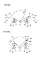
- FIG. 8 and Fig. 9 are schematic views of a second modification of the embodiment above.
- a door opening/closing device according to the second modification is different from the device in the embodiment above in terms of the structure of the door switch. The following will therefore describe only the structure of the door switch and will not detail the other arrangements.
- the components identical with those in the embodiment above will be denoted by the same reference numerals.
- a door switch 12 of the second modification includes a shaft 71 which is fixed to a base plate 9 and extends orthogonal to the base plate 9, a fan-shaped plate-like first rotatable component 72 which is arranged to be in parallel to the base plate 9 and to be rotatable about the shaft 71, a long plate-shaped second rotatable component 73 which is arranged to overlap the first rotatable component 72 and to be rotatable about the shaft 71, a spring 74 provided between the first rotatable component 72 and the second rotatable component 73, a magnetic sensor 75 attached to the first rotatable component 72, a magnet 76 attached to the second rotatable component 73, a first stopper 77 which is fixed to the base plate 9 to prevent the rotation of the first rotatable component 72 (i.e.
- the first rotatable component 72 is rotatably connected to the shaft 71, at a part close to the center of the fan.
- the magnetic sensor 75 is fixed to a point which is near the arc edge of the fan-shaped first rotatable component 72 and is near the linear edge on the side opposite to the linear edge that the first stopper 77 contacts.
- the second rotatable component 73 is a long plate-shaped component whose length is substantially identical with the diameter of the first rotatable component 72.
- This second rotatable component 73 is rotatably connected to a part of the shaft 71 in the vicinity of one end, whereas the magnet 76 is fixed to a part of the shaft 71 in the vicinity of the other end.
- the second rotatable component 73 is arranged so that the distance between the shaft 71 and the magnet 76 is identical with the distance between the shaft 71 and the magnetic sensor 75.
- An end of the spring 74 is fixed to a part of the first rotatable component 72, which part is in the vicinity of the linear edge contacting the first stopper 77 and substantially at a central part of the first rotatable component 72 in the radial directions.
- the other end of the spring 74 is fixed to a substantially central part of the second rotatable component 73 in the longitudinal directions.
- the spring 74 biases the first rotatable component 72 to rotate the component in one direction about the shaft 71 (i.e., in the counterclockwise direction in Fig. 8 , as indicated by the arrow R1), and also biases the second rotatable component 73 to rotate the component in the other direction about the shaft 71 (i.e., in the clockwise direction in Fig. 8 , as indicated by the arrow R2).
- the biasing components 57a and 57b move in the closing directions on account of the closing operations of the doors 100a and 100b, as shown in Fig. 8(b) , the biasing components 57a and 57b contact the edge portions of the first rotatable component 72 and the second rotatable component 73, respectively. More specifically, the biasing component 57a contacts the edge portion of the first rotatable component 72, which linearly extends in the radial directions. On the other hand, the biasing component 57b contacts the edge portion of the second rotatable component 73, which linearly extends in the longitudinal directions.
- the first rotatable component 72 is biased by the biasing component 57a and rotates about the shaft 71 away from the first stopper 77 (i.e., in the direction indicated by the arrow R2 in Fig. 8 ), against the biasing force of the spring 74.
- the second rotatable component 73 is biased by the biasing component 57b and rotates about the shaft 71 away from the second stopper 78 (i.e., in the direction indicated by the arrow R1 in Fig. 8 ), against the biasing force of the spring 74.
- the magnetic sensor 75 and the magnet 76 move to approach each other.
- the magnetic sensor 75 overlaps the magnet 76. In other words, the distance between the magnet 76 and the magnetic sensor 75 becomes the shortest.
- the magnetic sensor 75 detects a magnetic force of the magnet 76 when the magnet 75 falls within a predetermined range around the sensor (hereinafter, the detection range of the magnetic sensor 75), and outputs a detection signal to the control unit of the door opening/closing device.
- the distance between the first rotatable component 72 and the second rotatable component 73 is adjusted so that the magnet 76 falls within the detection range of the magnetic sensor 75 only when the magnet 76 overlaps the magnetic sensor 75 (i.e., only when the distance between the magnet 76 and the magnetic sensor 75 becomes the shortest). For this reason, the magnetic sensor 75 outputs the detection signal only when both of the two doors 100a and 100b are at the full-closed positions.
- a door switch 12 includes a first rotatable component 72 (first passive component) which is provided to be rotatable relative to a base plate 9 (vehicle main body) and is biased when one door 100a moves toward the full-closed position, a second rotatable component 73 (second passive component) which is provided to be rotatable relative to the base plate 9 and the first rotatable component 72 and is biased when the other door 100b moves toward the full-closed position, a magnetic sensor 75 (detection unit) which outputs a detection signal when the first rotatable component 72 and the second rotatable component 73 take predetermined relative positions and the magnet 76 gets close to a detection range, and a spring 74 (biasing member) which biases the first rotatable component 72 and the second rotatable component 73 to prevent the first rotatable component 72 and the second rotatable component 73 from taking the predetermined relative positions (i.e., the relative positions at which
- the predetermined relative positions are relative positions of the first rotatable component 72 and the second rotatable component 73 when the first rotatable component 72 and the second rotatable component 73 are biased by the biasing components 57a and 57b attached to the double doors 100a and 100b against the biasing force of the spring 74 and eventually both of the two doors 100a and 100b reach the full-closed positions.
- the biasing force of the spring 74 prevents the first rotatable component 72 and the second rotatable component 73 from taking the aforesaid relative positions, with the result that the magnet 76 does not fall within the detection range of the magnetic sensor 75 and no detection signal is output from the magnetic sensor 75 to the control unit. This makes it possible to certainly detect whether both of the double doors 100a and 100b are at the full-closed positions, without requiring another switch.
- the first rotatable component 72 and the second rotatable component 73 are rotatably attached to the shaft 71 (rotation axis) which is fixed to the base plate 9, and the shaft 71 extends in the directions vertical to the flat plate-shaped doors 100a and 100b (i.e., in the width directions of the vehicle).
- the first rotatable component 72 and the second rotatable component 73 are formed to be flat plates and arranged so that the width directions of these components are in parallel to the shaft 71. This makes it possible to reduce the size of the door switch 12 in the width directions of the vehicle.
- the magnetic sensor 75 first detection unit
- the magnet 76 second detection unit
- the magnetic sensor 75 outputs a detection signal.
- the magnetic sensor 75 is provided at a position further from the shaft 71 than the position on the first rotatable component 72 at which the biasing force of the biasing component 57a is exerted.
- the magnet 76 is provided at a position further from the shaft 71 than the position on the second rotatable component 73 at which the biasing force of the biasing component 57a is exerted.
- the degree of change in the relative positions of the magnetic sensor 75 and the magnet 76 is great.
- a thin matter caught in between the closing doors 100a and 100b is detectable without increasing the sensitivity of the sensor.
- a first spring holding unit 81 is fixed in the vicinity of the first stopper 77 on the base plate 9 to protrude from the base plate 9. Furthermore, in the vicinity of the second stopper 78, a second spring holding unit 82 is fixed to protrude from the base plate 9. Between the first spring holding unit 81 and the first rotatable component 72 is provided a first spring 83. This first spring 83 pulls the first rotatable component 72 to cause the first rotatable component 72 to approach the first stopper 77. Between the second spring holding unit 82 and the second rotatable component 73 is provided a second spring 84. The second spring 84 pulls the second rotatable component 73 to cause the second rotatable component 73 to approach the second stopper 78.
- the arrangement shown in Fig. 10 also allows the door switch 12 to output a detection signal only when both of the two doors reach the respective full-closed positions.
- the first rotatable component 72 may be L-shaped or V-shaped as indicated by, for example, a first rotatable component 72' shown in Fig. 11 . This reduces the weight of the first rotatable component 72' and also reduces the space required for the rotation of the first rotatable component 72'.
- the rotation axis of the first rotatable component 72 and the rotation axis of the second rotatable component 73 may be provided at different locations, as individual components.
- the present invention can be used for a door opening/closing device for closing and opening double doors and a door switch for detecting whether the double doors are closed, which are provided in a railroad vehicle.
Landscapes
- Engineering & Computer Science (AREA)
- Mechanical Engineering (AREA)
- Power-Operated Mechanisms For Wings (AREA)
Applications Claiming Priority (2)
| Application Number | Priority Date | Filing Date | Title |
|---|---|---|---|
| JP2009148966 | 2009-06-23 | ||
| PCT/JP2010/059180 WO2010150623A1 (ja) | 2009-06-23 | 2010-05-31 | 鉄道車両用ドアスイッチ及びそれを備えた鉄道車両用ドア開閉装置 |
Publications (3)
| Publication Number | Publication Date |
|---|---|
| EP2447130A1 true EP2447130A1 (de) | 2012-05-02 |
| EP2447130A4 EP2447130A4 (de) | 2013-06-05 |
| EP2447130B1 EP2447130B1 (de) | 2019-02-06 |
Family
ID=43386396
Family Applications (1)
| Application Number | Title | Priority Date | Filing Date |
|---|---|---|---|
| EP10791941.7A Not-in-force EP2447130B1 (de) | 2009-06-23 | 2010-05-31 | Türschalter für schienenfahrzeug, und türöffnungs- bzw. -schliessvorrichtung zur verwendung in einem schienenfahrzeug und mit diesem türschalter |
Country Status (6)
| Country | Link |
|---|---|
| EP (1) | EP2447130B1 (de) |
| JP (1) | JP5404786B2 (de) |
| CN (1) | CN102803043B (de) |
| HK (1) | HK1176913A1 (de) |
| TW (1) | TWI558900B (de) |
| WO (1) | WO2010150623A1 (de) |
Cited By (3)
| Publication number | Priority date | Publication date | Assignee | Title |
|---|---|---|---|---|
| ITUD20130106A1 (it) * | 2013-08-09 | 2015-02-10 | Mios Elettronica S R L | Apparecchiatura per l'apertura/chiusura di una porta per mezzi di trasporto e procedimento di apertura/chiusura di una porta |
| EP3015337A1 (de) * | 2014-10-31 | 2016-05-04 | Nabtesco Corporation | Türverriegelungsvorrichtung für fahrzeuge |
| EP3674167A1 (de) * | 2018-12-26 | 2020-07-01 | Nabtesco Corporation | Fahrzeugtürschalter und verfahren zum befestigen des fahrzeugtürschalters |
Families Citing this family (3)
| Publication number | Priority date | Publication date | Assignee | Title |
|---|---|---|---|---|
| JP6692576B2 (ja) * | 2016-06-01 | 2020-05-13 | 公益財団法人鉄道総合技術研究所 | 検知装置の短絡構造 |
| CN107795225B (zh) * | 2017-11-17 | 2019-08-27 | 湖南铁道职业技术学院天一实业有限公司 | 一种机车车门自动开、闭控制方法 |
| JP7141900B2 (ja) * | 2018-09-18 | 2022-09-26 | ナブテスコ株式会社 | ロック装置、およびロック装置を備えるドア駆動ユニット |
Citations (2)
| Publication number | Priority date | Publication date | Assignee | Title |
|---|---|---|---|---|
| DE3500958A1 (de) * | 1985-01-14 | 1986-07-17 | Knorr-Bremse AG, 8000 München | Steuervorrichtung fuer tueren |
| FR2696497A1 (fr) * | 1992-10-05 | 1994-04-08 | Fuji Electric Co Ltd | Dispositif de fermeture de porte de véhicule. |
Family Cites Families (11)
| Publication number | Priority date | Publication date | Assignee | Title |
|---|---|---|---|---|
| GB954592A (en) * | 1961-01-11 | 1964-04-08 | Kunimori Mariyama | Apparatus for opening and closing the door of a vehicle |
| JPS4324933Y1 (de) * | 1965-06-28 | 1968-10-19 | ||
| JPS4324932Y1 (de) * | 1965-06-28 | 1968-10-19 | ||
| JPS5229364Y2 (de) * | 1974-12-09 | 1977-07-05 | ||
| JPS60157468U (ja) * | 1984-03-30 | 1985-10-19 | 株式会社日立製作所 | 車両用戸締り検知装置 |
| JP3074116B2 (ja) * | 1994-12-12 | 2000-08-07 | 株式会社大井製作所 | ドアクロージャ |
| JPH09301158A (ja) * | 1996-05-14 | 1997-11-25 | Koshin Seikosho:Kk | 扉の閉鎖確認装置 |
| US5893236A (en) * | 1997-05-13 | 1999-04-13 | Westinghouse Air Brake Company | Power operator for sliding plug doors |
| US6032416A (en) * | 1998-06-18 | 2000-03-07 | Westinghouse Air Brake Company | Transit vehicle door |
| JP3485315B2 (ja) | 2001-04-17 | 2004-01-13 | 東日本トランスポ−テック株式会社 | 鉄道車両用ドアの開閉装置 |
| TWI231336B (en) * | 2004-01-20 | 2005-04-21 | Jin-Shan Hung | Electrical roll shutter door |
-
2010
- 2010-05-31 CN CN201080027837.5A patent/CN102803043B/zh active Active
- 2010-05-31 EP EP10791941.7A patent/EP2447130B1/de not_active Not-in-force
- 2010-05-31 WO PCT/JP2010/059180 patent/WO2010150623A1/ja active Application Filing
- 2010-05-31 JP JP2011519710A patent/JP5404786B2/ja active Active
- 2010-06-08 TW TW099118573A patent/TWI558900B/zh active
-
2013
- 2013-03-27 HK HK13103871.3A patent/HK1176913A1/zh unknown
Patent Citations (2)
| Publication number | Priority date | Publication date | Assignee | Title |
|---|---|---|---|---|
| DE3500958A1 (de) * | 1985-01-14 | 1986-07-17 | Knorr-Bremse AG, 8000 München | Steuervorrichtung fuer tueren |
| FR2696497A1 (fr) * | 1992-10-05 | 1994-04-08 | Fuji Electric Co Ltd | Dispositif de fermeture de porte de véhicule. |
Non-Patent Citations (1)
| Title |
|---|
| See also references of WO2010150623A1 * |
Cited By (5)
| Publication number | Priority date | Publication date | Assignee | Title |
|---|---|---|---|---|
| ITUD20130106A1 (it) * | 2013-08-09 | 2015-02-10 | Mios Elettronica S R L | Apparecchiatura per l'apertura/chiusura di una porta per mezzi di trasporto e procedimento di apertura/chiusura di una porta |
| EP3015337A1 (de) * | 2014-10-31 | 2016-05-04 | Nabtesco Corporation | Türverriegelungsvorrichtung für fahrzeuge |
| US10233681B2 (en) | 2014-10-31 | 2019-03-19 | Nabtesco Corporation | Vehicle door locking device |
| EP3674167A1 (de) * | 2018-12-26 | 2020-07-01 | Nabtesco Corporation | Fahrzeugtürschalter und verfahren zum befestigen des fahrzeugtürschalters |
| US11454058B2 (en) | 2018-12-26 | 2022-09-27 | Nabtesco Corporation | Vehicle door switch and method for attaching vehicle door switch |
Also Published As
| Publication number | Publication date |
|---|---|
| EP2447130A4 (de) | 2013-06-05 |
| JPWO2010150623A1 (ja) | 2012-12-10 |
| HK1176913A1 (zh) | 2013-08-09 |
| CN102803043A (zh) | 2012-11-28 |
| CN102803043B (zh) | 2016-09-21 |
| EP2447130B1 (de) | 2019-02-06 |
| JP5404786B2 (ja) | 2014-02-05 |
| TW201111609A (en) | 2011-04-01 |
| TWI558900B (zh) | 2016-11-21 |
| WO2010150623A1 (ja) | 2010-12-29 |
Similar Documents
| Publication | Publication Date | Title |
|---|---|---|
| EP2447130B1 (de) | Türschalter für schienenfahrzeug, und türöffnungs- bzw. -schliessvorrichtung zur verwendung in einem schienenfahrzeug und mit diesem türschalter | |
| EP3165856B1 (de) | Kühlschrank | |
| US6519986B2 (en) | Locking device | |
| KR101976690B1 (ko) | 자동차용 도어 개폐장치 | |
| US10589758B2 (en) | Plug door opening-closing device | |
| US7161100B1 (en) | Limit switch mechanism for door opening | |
| EP2653356B1 (de) | Elektrische fahrzeugverriegelungsvorrichtung | |
| JP2014024134A (ja) | 力制御電動ハンド | |
| JP2011111819A (ja) | 車両用ドア開閉装置 | |
| JP6221444B2 (ja) | 車両用ステップ装置 | |
| US11485222B2 (en) | Apparatus for opening and closing a lid of a vehicle | |
| US20140352216A1 (en) | Vehicle doors closer and working unit for a vehicle doors closer | |
| JP5602405B2 (ja) | スライドドア自動開閉装置 | |
| US20160153212A1 (en) | Electronic latch for vehicle doors | |
| US9822575B2 (en) | Movable body driving device | |
| JP5852799B2 (ja) | 異物検知センサの固定構造及び異物検知装置 | |
| JP4994792B2 (ja) | ドア開閉装置 | |
| JP2011105139A (ja) | ウィンドウレギュレータ装置 | |
| JP2020167397A (ja) | ロードポート | |
| JP2008057277A (ja) | 開閉装置 | |
| JP5072785B2 (ja) | 撮像装置 | |
| US20110144867A1 (en) | System for sensing the position of a movable bar | |
| JP7349378B2 (ja) | 移動停止機構およびその移動停止機構を備えた移動装置 | |
| JP4343634B2 (ja) | 自動改札機用ドア駆動装置 | |
| CN116867603A (zh) | 用于夹持开口部件的定位设备 |
Legal Events
| Date | Code | Title | Description |
|---|---|---|---|
| PUAI | Public reference made under article 153(3) epc to a published international application that has entered the european phase |
Free format text: ORIGINAL CODE: 0009012 |
|
| 17P | Request for examination filed |
Effective date: 20120113 |
|
| AK | Designated contracting states |
Kind code of ref document: A1 Designated state(s): AL AT BE BG CH CY CZ DE DK EE ES FI FR GB GR HR HU IE IS IT LI LT LU LV MC MK MT NL NO PL PT RO SE SI SK SM TR |
|
| DAX | Request for extension of the european patent (deleted) | ||
| A4 | Supplementary search report drawn up and despatched |
Effective date: 20130507 |
|
| RIC1 | Information provided on ipc code assigned before grant |
Ipc: B61D 19/02 20060101AFI20130430BHEP Ipc: E05B 65/12 20060101ALI20130430BHEP |
|
| STAA | Information on the status of an ep patent application or granted ep patent |
Free format text: STATUS: EXAMINATION IS IN PROGRESS |
|
| 17Q | First examination report despatched |
Effective date: 20170117 |
|
| RIC1 | Information provided on ipc code assigned before grant |
Ipc: B61D 19/02 20060101AFI20170912BHEP |
|
| GRAP | Despatch of communication of intention to grant a patent |
Free format text: ORIGINAL CODE: EPIDOSNIGR1 |
|
| STAA | Information on the status of an ep patent application or granted ep patent |
Free format text: STATUS: GRANT OF PATENT IS INTENDED |
|
| INTG | Intention to grant announced |
Effective date: 20180822 |
|
| GRAS | Grant fee paid |
Free format text: ORIGINAL CODE: EPIDOSNIGR3 |
|
| GRAA | (expected) grant |
Free format text: ORIGINAL CODE: 0009210 |
|
| STAA | Information on the status of an ep patent application or granted ep patent |
Free format text: STATUS: THE PATENT HAS BEEN GRANTED |
|
| AK | Designated contracting states |
Kind code of ref document: B1 Designated state(s): AL AT BE BG CH CY CZ DE DK EE ES FI FR GB GR HR HU IE IS IT LI LT LU LV MC MK MT NL NO PL PT RO SE SI SK SM TR |
|
| REG | Reference to a national code |
Ref country code: GB Ref legal event code: FG4D |
|
| REG | Reference to a national code |
Ref country code: CH Ref legal event code: EP Ref country code: AT Ref legal event code: REF Ref document number: 1094710 Country of ref document: AT Kind code of ref document: T Effective date: 20190215 |
|
| REG | Reference to a national code |
Ref country code: DE Ref legal event code: R096 Ref document number: 602010056905 Country of ref document: DE |
|
| REG | Reference to a national code |
Ref country code: IE Ref legal event code: FG4D |
|
| REG | Reference to a national code |
Ref country code: NL Ref legal event code: MP Effective date: 20190206 |
|
| REG | Reference to a national code |
Ref country code: LT Ref legal event code: MG4D |
|
| PG25 | Lapsed in a contracting state [announced via postgrant information from national office to epo] |
Ref country code: FI Free format text: LAPSE BECAUSE OF FAILURE TO SUBMIT A TRANSLATION OF THE DESCRIPTION OR TO PAY THE FEE WITHIN THE PRESCRIBED TIME-LIMIT Effective date: 20190206 Ref country code: NO Free format text: LAPSE BECAUSE OF FAILURE TO SUBMIT A TRANSLATION OF THE DESCRIPTION OR TO PAY THE FEE WITHIN THE PRESCRIBED TIME-LIMIT Effective date: 20190506 Ref country code: PT Free format text: LAPSE BECAUSE OF FAILURE TO SUBMIT A TRANSLATION OF THE DESCRIPTION OR TO PAY THE FEE WITHIN THE PRESCRIBED TIME-LIMIT Effective date: 20190606 Ref country code: SE Free format text: LAPSE BECAUSE OF FAILURE TO SUBMIT A TRANSLATION OF THE DESCRIPTION OR TO PAY THE FEE WITHIN THE PRESCRIBED TIME-LIMIT Effective date: 20190206 Ref country code: LT Free format text: LAPSE BECAUSE OF FAILURE TO SUBMIT A TRANSLATION OF THE DESCRIPTION OR TO PAY THE FEE WITHIN THE PRESCRIBED TIME-LIMIT Effective date: 20190206 Ref country code: NL Free format text: LAPSE BECAUSE OF FAILURE TO SUBMIT A TRANSLATION OF THE DESCRIPTION OR TO PAY THE FEE WITHIN THE PRESCRIBED TIME-LIMIT Effective date: 20190206 |
|
| REG | Reference to a national code |
Ref country code: AT Ref legal event code: MK05 Ref document number: 1094710 Country of ref document: AT Kind code of ref document: T Effective date: 20190206 |
|
| PG25 | Lapsed in a contracting state [announced via postgrant information from national office to epo] |
Ref country code: GR Free format text: LAPSE BECAUSE OF FAILURE TO SUBMIT A TRANSLATION OF THE DESCRIPTION OR TO PAY THE FEE WITHIN THE PRESCRIBED TIME-LIMIT Effective date: 20190507 Ref country code: HR Free format text: LAPSE BECAUSE OF FAILURE TO SUBMIT A TRANSLATION OF THE DESCRIPTION OR TO PAY THE FEE WITHIN THE PRESCRIBED TIME-LIMIT Effective date: 20190206 Ref country code: LV Free format text: LAPSE BECAUSE OF FAILURE TO SUBMIT A TRANSLATION OF THE DESCRIPTION OR TO PAY THE FEE WITHIN THE PRESCRIBED TIME-LIMIT Effective date: 20190206 Ref country code: BG Free format text: LAPSE BECAUSE OF FAILURE TO SUBMIT A TRANSLATION OF THE DESCRIPTION OR TO PAY THE FEE WITHIN THE PRESCRIBED TIME-LIMIT Effective date: 20190506 Ref country code: IS Free format text: LAPSE BECAUSE OF FAILURE TO SUBMIT A TRANSLATION OF THE DESCRIPTION OR TO PAY THE FEE WITHIN THE PRESCRIBED TIME-LIMIT Effective date: 20190606 |
|
| PG25 | Lapsed in a contracting state [announced via postgrant information from national office to epo] |
Ref country code: SK Free format text: LAPSE BECAUSE OF FAILURE TO SUBMIT A TRANSLATION OF THE DESCRIPTION OR TO PAY THE FEE WITHIN THE PRESCRIBED TIME-LIMIT Effective date: 20190206 Ref country code: RO Free format text: LAPSE BECAUSE OF FAILURE TO SUBMIT A TRANSLATION OF THE DESCRIPTION OR TO PAY THE FEE WITHIN THE PRESCRIBED TIME-LIMIT Effective date: 20190206 Ref country code: DK Free format text: LAPSE BECAUSE OF FAILURE TO SUBMIT A TRANSLATION OF THE DESCRIPTION OR TO PAY THE FEE WITHIN THE PRESCRIBED TIME-LIMIT Effective date: 20190206 Ref country code: EE Free format text: LAPSE BECAUSE OF FAILURE TO SUBMIT A TRANSLATION OF THE DESCRIPTION OR TO PAY THE FEE WITHIN THE PRESCRIBED TIME-LIMIT Effective date: 20190206 Ref country code: IT Free format text: LAPSE BECAUSE OF FAILURE TO SUBMIT A TRANSLATION OF THE DESCRIPTION OR TO PAY THE FEE WITHIN THE PRESCRIBED TIME-LIMIT Effective date: 20190206 Ref country code: ES Free format text: LAPSE BECAUSE OF FAILURE TO SUBMIT A TRANSLATION OF THE DESCRIPTION OR TO PAY THE FEE WITHIN THE PRESCRIBED TIME-LIMIT Effective date: 20190206 Ref country code: AL Free format text: LAPSE BECAUSE OF FAILURE TO SUBMIT A TRANSLATION OF THE DESCRIPTION OR TO PAY THE FEE WITHIN THE PRESCRIBED TIME-LIMIT Effective date: 20190206 Ref country code: CZ Free format text: LAPSE BECAUSE OF FAILURE TO SUBMIT A TRANSLATION OF THE DESCRIPTION OR TO PAY THE FEE WITHIN THE PRESCRIBED TIME-LIMIT Effective date: 20190206 |
|
| REG | Reference to a national code |
Ref country code: DE Ref legal event code: R097 Ref document number: 602010056905 Country of ref document: DE |
|
| PG25 | Lapsed in a contracting state [announced via postgrant information from national office to epo] |
Ref country code: SM Free format text: LAPSE BECAUSE OF FAILURE TO SUBMIT A TRANSLATION OF THE DESCRIPTION OR TO PAY THE FEE WITHIN THE PRESCRIBED TIME-LIMIT Effective date: 20190206 Ref country code: PL Free format text: LAPSE BECAUSE OF FAILURE TO SUBMIT A TRANSLATION OF THE DESCRIPTION OR TO PAY THE FEE WITHIN THE PRESCRIBED TIME-LIMIT Effective date: 20190206 |
|
| PLBE | No opposition filed within time limit |
Free format text: ORIGINAL CODE: 0009261 |
|
| STAA | Information on the status of an ep patent application or granted ep patent |
Free format text: STATUS: NO OPPOSITION FILED WITHIN TIME LIMIT |
|
| REG | Reference to a national code |
Ref country code: CH Ref legal event code: PL |
|
| PG25 | Lapsed in a contracting state [announced via postgrant information from national office to epo] |
Ref country code: AT Free format text: LAPSE BECAUSE OF FAILURE TO SUBMIT A TRANSLATION OF THE DESCRIPTION OR TO PAY THE FEE WITHIN THE PRESCRIBED TIME-LIMIT Effective date: 20190206 |
|
| 26N | No opposition filed |
Effective date: 20191107 |
|
| PG25 | Lapsed in a contracting state [announced via postgrant information from national office to epo] |
Ref country code: LI Free format text: LAPSE BECAUSE OF NON-PAYMENT OF DUE FEES Effective date: 20190531 Ref country code: CH Free format text: LAPSE BECAUSE OF NON-PAYMENT OF DUE FEES Effective date: 20190531 Ref country code: MC Free format text: LAPSE BECAUSE OF FAILURE TO SUBMIT A TRANSLATION OF THE DESCRIPTION OR TO PAY THE FEE WITHIN THE PRESCRIBED TIME-LIMIT Effective date: 20190206 |
|
| REG | Reference to a national code |
Ref country code: BE Ref legal event code: MM Effective date: 20190531 |
|
| PG25 | Lapsed in a contracting state [announced via postgrant information from national office to epo] |
Ref country code: LU Free format text: LAPSE BECAUSE OF NON-PAYMENT OF DUE FEES Effective date: 20190531 Ref country code: SI Free format text: LAPSE BECAUSE OF FAILURE TO SUBMIT A TRANSLATION OF THE DESCRIPTION OR TO PAY THE FEE WITHIN THE PRESCRIBED TIME-LIMIT Effective date: 20190206 |
|
| PG25 | Lapsed in a contracting state [announced via postgrant information from national office to epo] |
Ref country code: TR Free format text: LAPSE BECAUSE OF FAILURE TO SUBMIT A TRANSLATION OF THE DESCRIPTION OR TO PAY THE FEE WITHIN THE PRESCRIBED TIME-LIMIT Effective date: 20190206 |
|
| PG25 | Lapsed in a contracting state [announced via postgrant information from national office to epo] |
Ref country code: IE Free format text: LAPSE BECAUSE OF NON-PAYMENT OF DUE FEES Effective date: 20190531 |
|
| PG25 | Lapsed in a contracting state [announced via postgrant information from national office to epo] |
Ref country code: BE Free format text: LAPSE BECAUSE OF NON-PAYMENT OF DUE FEES Effective date: 20190531 |
|
| PG25 | Lapsed in a contracting state [announced via postgrant information from national office to epo] |
Ref country code: CY Free format text: LAPSE BECAUSE OF FAILURE TO SUBMIT A TRANSLATION OF THE DESCRIPTION OR TO PAY THE FEE WITHIN THE PRESCRIBED TIME-LIMIT Effective date: 20190206 |
|
| PG25 | Lapsed in a contracting state [announced via postgrant information from national office to epo] |
Ref country code: MT Free format text: LAPSE BECAUSE OF FAILURE TO SUBMIT A TRANSLATION OF THE DESCRIPTION OR TO PAY THE FEE WITHIN THE PRESCRIBED TIME-LIMIT Effective date: 20190206 Ref country code: HU Free format text: LAPSE BECAUSE OF FAILURE TO SUBMIT A TRANSLATION OF THE DESCRIPTION OR TO PAY THE FEE WITHIN THE PRESCRIBED TIME-LIMIT; INVALID AB INITIO Effective date: 20100531 |
|
| PGFP | Annual fee paid to national office [announced via postgrant information from national office to epo] |
Ref country code: DE Payment date: 20210520 Year of fee payment: 12 Ref country code: FR Payment date: 20210525 Year of fee payment: 12 |
|
| PGFP | Annual fee paid to national office [announced via postgrant information from national office to epo] |
Ref country code: GB Payment date: 20210525 Year of fee payment: 12 |
|
| PG25 | Lapsed in a contracting state [announced via postgrant information from national office to epo] |
Ref country code: MK Free format text: LAPSE BECAUSE OF FAILURE TO SUBMIT A TRANSLATION OF THE DESCRIPTION OR TO PAY THE FEE WITHIN THE PRESCRIBED TIME-LIMIT Effective date: 20190206 |
|
| REG | Reference to a national code |
Ref country code: DE Ref legal event code: R119 Ref document number: 602010056905 Country of ref document: DE |
|
| GBPC | Gb: european patent ceased through non-payment of renewal fee |
Effective date: 20220531 |
|
| PG25 | Lapsed in a contracting state [announced via postgrant information from national office to epo] |
Ref country code: FR Free format text: LAPSE BECAUSE OF NON-PAYMENT OF DUE FEES Effective date: 20220531 |
|
| PG25 | Lapsed in a contracting state [announced via postgrant information from national office to epo] |
Ref country code: GB Free format text: LAPSE BECAUSE OF NON-PAYMENT OF DUE FEES Effective date: 20220531 Ref country code: DE Free format text: LAPSE BECAUSE OF NON-PAYMENT OF DUE FEES Effective date: 20221201 |