EP2447121A2 - Véhicule hybride et son procédé de contrôle - Google Patents
Véhicule hybride et son procédé de contrôle Download PDFInfo
- Publication number
- EP2447121A2 EP2447121A2 EP11008598A EP11008598A EP2447121A2 EP 2447121 A2 EP2447121 A2 EP 2447121A2 EP 11008598 A EP11008598 A EP 11008598A EP 11008598 A EP11008598 A EP 11008598A EP 2447121 A2 EP2447121 A2 EP 2447121A2
- Authority
- EP
- European Patent Office
- Prior art keywords
- clutch
- temperature
- motor
- epm
- magnet
- Prior art date
- Legal status (The legal status is an assumption and is not a legal conclusion. Google has not performed a legal analysis and makes no representation as to the accuracy of the status listed.)
- Granted
Links
- 238000000034 method Methods 0.000 title claims description 15
- 239000010720 hydraulic oil Substances 0.000 claims abstract description 26
- 230000007704 transition Effects 0.000 claims abstract description 7
- 239000003921 oil Substances 0.000 claims description 88
- 230000005347 demagnetization Effects 0.000 description 15
- 230000005540 biological transmission Effects 0.000 description 10
- 238000005461 lubrication Methods 0.000 description 9
- 230000020169 heat generation Effects 0.000 description 6
- 238000012545 processing Methods 0.000 description 6
- 238000004891 communication Methods 0.000 description 4
- 230000007423 decrease Effects 0.000 description 4
- 238000010586 diagram Methods 0.000 description 4
- 230000001172 regenerating effect Effects 0.000 description 4
- 230000006866 deterioration Effects 0.000 description 3
- 238000013021 overheating Methods 0.000 description 3
- 238000010276 construction Methods 0.000 description 2
- 238000001816 cooling Methods 0.000 description 2
- 230000002265 prevention Effects 0.000 description 2
- 230000035939 shock Effects 0.000 description 2
- 230000001360 synchronised effect Effects 0.000 description 2
- 230000001133 acceleration Effects 0.000 description 1
- 230000007812 deficiency Effects 0.000 description 1
- 230000000881 depressing effect Effects 0.000 description 1
- 239000012530 fluid Substances 0.000 description 1
- 230000008929 regeneration Effects 0.000 description 1
- 238000011069 regeneration method Methods 0.000 description 1
Images


Classifications
-
- B—PERFORMING OPERATIONS; TRANSPORTING
- B60—VEHICLES IN GENERAL
- B60W—CONJOINT CONTROL OF VEHICLE SUB-UNITS OF DIFFERENT TYPE OR DIFFERENT FUNCTION; CONTROL SYSTEMS SPECIALLY ADAPTED FOR HYBRID VEHICLES; ROAD VEHICLE DRIVE CONTROL SYSTEMS FOR PURPOSES NOT RELATED TO THE CONTROL OF A PARTICULAR SUB-UNIT
- B60W10/00—Conjoint control of vehicle sub-units of different type or different function
- B60W10/02—Conjoint control of vehicle sub-units of different type or different function including control of driveline clutches
- B60W10/023—Fluid clutches
-
- B—PERFORMING OPERATIONS; TRANSPORTING
- B60—VEHICLES IN GENERAL
- B60K—ARRANGEMENT OR MOUNTING OF PROPULSION UNITS OR OF TRANSMISSIONS IN VEHICLES; ARRANGEMENT OR MOUNTING OF PLURAL DIVERSE PRIME-MOVERS IN VEHICLES; AUXILIARY DRIVES FOR VEHICLES; INSTRUMENTATION OR DASHBOARDS FOR VEHICLES; ARRANGEMENTS IN CONNECTION WITH COOLING, AIR INTAKE, GAS EXHAUST OR FUEL SUPPLY OF PROPULSION UNITS IN VEHICLES
- B60K6/00—Arrangement or mounting of plural diverse prime-movers for mutual or common propulsion, e.g. hybrid propulsion systems comprising electric motors and internal combustion engines ; Control systems therefor, i.e. systems controlling two or more prime movers, or controlling one of these prime movers and any of the transmission, drive or drive units Informative references: mechanical gearings with secondary electric drive F16H3/72; arrangements for handling mechanical energy structurally associated with the dynamo-electric machine H02K7/00; machines comprising structurally interrelated motor and generator parts H02K51/00; dynamo-electric machines not otherwise provided for in H02K see H02K99/00
- B60K6/20—Arrangement or mounting of plural diverse prime-movers for mutual or common propulsion, e.g. hybrid propulsion systems comprising electric motors and internal combustion engines ; Control systems therefor, i.e. systems controlling two or more prime movers, or controlling one of these prime movers and any of the transmission, drive or drive units Informative references: mechanical gearings with secondary electric drive F16H3/72; arrangements for handling mechanical energy structurally associated with the dynamo-electric machine H02K7/00; machines comprising structurally interrelated motor and generator parts H02K51/00; dynamo-electric machines not otherwise provided for in H02K see H02K99/00 the prime-movers consisting of electric motors and internal combustion engines, e.g. HEVs
- B60K6/42—Arrangement or mounting of plural diverse prime-movers for mutual or common propulsion, e.g. hybrid propulsion systems comprising electric motors and internal combustion engines ; Control systems therefor, i.e. systems controlling two or more prime movers, or controlling one of these prime movers and any of the transmission, drive or drive units Informative references: mechanical gearings with secondary electric drive F16H3/72; arrangements for handling mechanical energy structurally associated with the dynamo-electric machine H02K7/00; machines comprising structurally interrelated motor and generator parts H02K51/00; dynamo-electric machines not otherwise provided for in H02K see H02K99/00 the prime-movers consisting of electric motors and internal combustion engines, e.g. HEVs characterised by the architecture of the hybrid electric vehicle
- B60K6/48—Parallel type
-
- B—PERFORMING OPERATIONS; TRANSPORTING
- B60—VEHICLES IN GENERAL
- B60L—PROPULSION OF ELECTRICALLY-PROPELLED VEHICLES; SUPPLYING ELECTRIC POWER FOR AUXILIARY EQUIPMENT OF ELECTRICALLY-PROPELLED VEHICLES; ELECTRODYNAMIC BRAKE SYSTEMS FOR VEHICLES IN GENERAL; MAGNETIC SUSPENSION OR LEVITATION FOR VEHICLES; MONITORING OPERATING VARIABLES OF ELECTRICALLY-PROPELLED VEHICLES; ELECTRIC SAFETY DEVICES FOR ELECTRICALLY-PROPELLED VEHICLES
- B60L50/00—Electric propulsion with power supplied within the vehicle
- B60L50/50—Electric propulsion with power supplied within the vehicle using propulsion power supplied by batteries or fuel cells
-
- B—PERFORMING OPERATIONS; TRANSPORTING
- B60—VEHICLES IN GENERAL
- B60W—CONJOINT CONTROL OF VEHICLE SUB-UNITS OF DIFFERENT TYPE OR DIFFERENT FUNCTION; CONTROL SYSTEMS SPECIALLY ADAPTED FOR HYBRID VEHICLES; ROAD VEHICLE DRIVE CONTROL SYSTEMS FOR PURPOSES NOT RELATED TO THE CONTROL OF A PARTICULAR SUB-UNIT
- B60W10/00—Conjoint control of vehicle sub-units of different type or different function
- B60W10/04—Conjoint control of vehicle sub-units of different type or different function including control of propulsion units
- B60W10/08—Conjoint control of vehicle sub-units of different type or different function including control of propulsion units including control of electric propulsion units, e.g. motors or generators
-
- B—PERFORMING OPERATIONS; TRANSPORTING
- B60—VEHICLES IN GENERAL
- B60W—CONJOINT CONTROL OF VEHICLE SUB-UNITS OF DIFFERENT TYPE OR DIFFERENT FUNCTION; CONTROL SYSTEMS SPECIALLY ADAPTED FOR HYBRID VEHICLES; ROAD VEHICLE DRIVE CONTROL SYSTEMS FOR PURPOSES NOT RELATED TO THE CONTROL OF A PARTICULAR SUB-UNIT
- B60W10/00—Conjoint control of vehicle sub-units of different type or different function
- B60W10/30—Conjoint control of vehicle sub-units of different type or different function including control of auxiliary equipment, e.g. air-conditioning compressors or oil pumps
-
- B—PERFORMING OPERATIONS; TRANSPORTING
- B60—VEHICLES IN GENERAL
- B60W—CONJOINT CONTROL OF VEHICLE SUB-UNITS OF DIFFERENT TYPE OR DIFFERENT FUNCTION; CONTROL SYSTEMS SPECIALLY ADAPTED FOR HYBRID VEHICLES; ROAD VEHICLE DRIVE CONTROL SYSTEMS FOR PURPOSES NOT RELATED TO THE CONTROL OF A PARTICULAR SUB-UNIT
- B60W20/00—Control systems specially adapted for hybrid vehicles
-
- B—PERFORMING OPERATIONS; TRANSPORTING
- B60—VEHICLES IN GENERAL
- B60W—CONJOINT CONTROL OF VEHICLE SUB-UNITS OF DIFFERENT TYPE OR DIFFERENT FUNCTION; CONTROL SYSTEMS SPECIALLY ADAPTED FOR HYBRID VEHICLES; ROAD VEHICLE DRIVE CONTROL SYSTEMS FOR PURPOSES NOT RELATED TO THE CONTROL OF A PARTICULAR SUB-UNIT
- B60W30/00—Purposes of road vehicle drive control systems not related to the control of a particular sub-unit, e.g. of systems using conjoint control of vehicle sub-units, or advanced driver assistance systems for ensuring comfort, stability and safety or drive control systems for propelling or retarding the vehicle
- B60W30/18—Propelling the vehicle
- B60W30/18009—Propelling the vehicle related to particular drive situations
- B60W30/18027—Drive off, accelerating from standstill
-
- B—PERFORMING OPERATIONS; TRANSPORTING
- B60—VEHICLES IN GENERAL
- B60W—CONJOINT CONTROL OF VEHICLE SUB-UNITS OF DIFFERENT TYPE OR DIFFERENT FUNCTION; CONTROL SYSTEMS SPECIALLY ADAPTED FOR HYBRID VEHICLES; ROAD VEHICLE DRIVE CONTROL SYSTEMS FOR PURPOSES NOT RELATED TO THE CONTROL OF A PARTICULAR SUB-UNIT
- B60W30/00—Purposes of road vehicle drive control systems not related to the control of a particular sub-unit, e.g. of systems using conjoint control of vehicle sub-units, or advanced driver assistance systems for ensuring comfort, stability and safety or drive control systems for propelling or retarding the vehicle
- B60W30/18—Propelling the vehicle
- B60W30/184—Preventing damage resulting from overload or excessive wear of the driveline
- B60W30/186—Preventing damage resulting from overload or excessive wear of the driveline excessive wear or burn out of friction elements, e.g. clutches
-
- F—MECHANICAL ENGINEERING; LIGHTING; HEATING; WEAPONS; BLASTING
- F16—ENGINEERING ELEMENTS AND UNITS; GENERAL MEASURES FOR PRODUCING AND MAINTAINING EFFECTIVE FUNCTIONING OF MACHINES OR INSTALLATIONS; THERMAL INSULATION IN GENERAL
- F16H—GEARING
- F16H61/00—Control functions within control units of change-speed- or reversing-gearings for conveying rotary motion ; Control of exclusively fluid gearing, friction gearing, gearings with endless flexible members or other particular types of gearing
- F16H61/0021—Generation or control of line pressure
- F16H61/0025—Supply of control fluid; Pumps therefore
- F16H61/0031—Supply of control fluid; Pumps therefore using auxiliary pumps, e.g. pump driven by a different power source than the engine
-
- B—PERFORMING OPERATIONS; TRANSPORTING
- B60—VEHICLES IN GENERAL
- B60W—CONJOINT CONTROL OF VEHICLE SUB-UNITS OF DIFFERENT TYPE OR DIFFERENT FUNCTION; CONTROL SYSTEMS SPECIALLY ADAPTED FOR HYBRID VEHICLES; ROAD VEHICLE DRIVE CONTROL SYSTEMS FOR PURPOSES NOT RELATED TO THE CONTROL OF A PARTICULAR SUB-UNIT
- B60W2510/00—Input parameters relating to a particular sub-units
- B60W2510/02—Clutches
- B60W2510/0291—Clutch temperature
-
- B—PERFORMING OPERATIONS; TRANSPORTING
- B60—VEHICLES IN GENERAL
- B60W—CONJOINT CONTROL OF VEHICLE SUB-UNITS OF DIFFERENT TYPE OR DIFFERENT FUNCTION; CONTROL SYSTEMS SPECIALLY ADAPTED FOR HYBRID VEHICLES; ROAD VEHICLE DRIVE CONTROL SYSTEMS FOR PURPOSES NOT RELATED TO THE CONTROL OF A PARTICULAR SUB-UNIT
- B60W2510/00—Input parameters relating to a particular sub-units
- B60W2510/08—Electric propulsion units
- B60W2510/081—Speed
-
- B—PERFORMING OPERATIONS; TRANSPORTING
- B60—VEHICLES IN GENERAL
- B60Y—INDEXING SCHEME RELATING TO ASPECTS CROSS-CUTTING VEHICLE TECHNOLOGY
- B60Y2200/00—Type of vehicle
- B60Y2200/90—Vehicles comprising electric prime movers
- B60Y2200/92—Hybrid vehicles
-
- F—MECHANICAL ENGINEERING; LIGHTING; HEATING; WEAPONS; BLASTING
- F16—ENGINEERING ELEMENTS AND UNITS; GENERAL MEASURES FOR PRODUCING AND MAINTAINING EFFECTIVE FUNCTIONING OF MACHINES OR INSTALLATIONS; THERMAL INSULATION IN GENERAL
- F16D—COUPLINGS FOR TRANSMITTING ROTATION; CLUTCHES; BRAKES
- F16D2500/00—External control of clutches by electric or electronic means
- F16D2500/10—System to be controlled
- F16D2500/106—Engine
- F16D2500/1066—Hybrid
-
- F—MECHANICAL ENGINEERING; LIGHTING; HEATING; WEAPONS; BLASTING
- F16—ENGINEERING ELEMENTS AND UNITS; GENERAL MEASURES FOR PRODUCING AND MAINTAINING EFFECTIVE FUNCTIONING OF MACHINES OR INSTALLATIONS; THERMAL INSULATION IN GENERAL
- F16D—COUPLINGS FOR TRANSMITTING ROTATION; CLUTCHES; BRAKES
- F16D2500/00—External control of clutches by electric or electronic means
- F16D2500/30—Signal inputs
- F16D2500/316—Other signal inputs not covered by the groups above
- F16D2500/3168—Temperature detection of any component of the control system
-
- Y—GENERAL TAGGING OF NEW TECHNOLOGICAL DEVELOPMENTS; GENERAL TAGGING OF CROSS-SECTIONAL TECHNOLOGIES SPANNING OVER SEVERAL SECTIONS OF THE IPC; TECHNICAL SUBJECTS COVERED BY FORMER USPC CROSS-REFERENCE ART COLLECTIONS [XRACs] AND DIGESTS
- Y02—TECHNOLOGIES OR APPLICATIONS FOR MITIGATION OR ADAPTATION AGAINST CLIMATE CHANGE
- Y02T—CLIMATE CHANGE MITIGATION TECHNOLOGIES RELATED TO TRANSPORTATION
- Y02T10/00—Road transport of goods or passengers
- Y02T10/60—Other road transportation technologies with climate change mitigation effect
- Y02T10/62—Hybrid vehicles
Definitions
- the present invention relates to a control of a hybrid vehicle, particularly to a control of an electrical oil pump mounted in a hybrid vehicle.
- a hybrid vehicle which can travel using a drive source of at least one of an engine and a motor generator and in which a drive system is constructed by connecting the engine, a first clutch, the motor generator, a second clutch and drive wheels in this order.
- a hybrid vehicle an EV mode in which the vehicle travels using only the motor generator as a power source is set by releasing the first clutch and engaging the second clutch to stop the engine, and an HEV mode in which the vehicle travels using the engine and the motor generator as power sources is set by engaging both the first and second clutches.
- Hydraulic pressures supplied to the first clutch and the second clutch are produced by a mechanical oil pump driven and rotated by the engine and by an electrical oil pump driven and rotated by an electric motor, wherein the mechanical oil pump is mainly used in the HEV mode and the electrical oil pump is used in the EV motor.
- the electrical oil pump is actuated in addition to the mechanical oil pump to suppress heat generation by slip of the second clutch.
- This enables the second clutch to be lubricated and cooled by hydraulic oil supplied from the electrical oil pump in addition to by hydraulic oil supplied from the mechanical oil pump.
- the temperature of an operating motor which drives the electrical oil pump increases due to the high oil temperature and also by self-heat generation caused by the drive of the operating motor. Accordingly, the temperature of a motor magnet provided in the operating motor also increases. If the temperature of the motor magnet increases and exceeds a predetermined demagnetization temperature, a magnetic force of the motor magnet is reduced. Even if the motor magnet is cooled thereafter, the magnetic force is not restored, whereby the performance of the electrical oil pump is reduced.
- the second clutch is insufficiently lubricated during the WSC control, which may possibly lead to deterioration of the second clutch due to overheating and a reduction in the travel performance of the vehicle.
- An object of the present invention is to ensure a lubrication flow rate of a second clutch while preventing a reduction in the performance of an electrical oil pump when oil temperature is high.
- a hybrid vehicle including an engine and a motor generator as drive sources, a first clutch interposed between the engine and the motor generator and released by supplying hydraulic oil, and a second clutch interposed between the motor generator and drive wheels and engaged by supplying the hydraulic oil, the hybrid vehicle being able to travel in a hybrid travel mode in which the engine and the motor generator are used as the drive sources by engaging the first clutch and the second clutch, is provided.
- the hybrid vehicle includes a mechanical oil pump which discharges the hydraulic oil by being driven by a drive force of the vehicle; an electrical oil pump which discharges the hydraulic oil by being driven by an electric motor for pump; a start-time slip control unit which causes the second clutch to transition to an engaged state after setting the second clutch in a slip state when the vehicle starts in the hybrid start mode; a motor temperature estimating unit which estimates the temperature of a magnet of the electric motor based on the temperature of the hydraulic oil and an operating condition of the electric motor when the second clutch is controlled to be in the slip state; and a motor restricting unit which restricts and reduces an output torque and a lower limit rotation speed of the electric motor when the estimated temperature of the magnet exceeds a restrictive temperature.
- a control method for a hybrid vehicle including an engine and a motor generator as drive sources, a first clutch interposed between the engine and the motor generator and released by supplying hydraulic oil, a second clutch interposed between the motor generator and drive wheels and engaged by supplying the hydraulic oil, a mechanical oil pump which discharges the hydraulic oil by being driven by a drive force of the vehicle, and an electrical oil pump which discharges the hydraulic oil by being driven by an electric motor for pump, the hybrid vehicle being able to travel in a hybrid travel mode in which the engine and the motor generator are used as the drive sources by engaging the first clutch and the second clutch, is provided.
- the control method includes causing the second clutch to transition to an engaged state after setting the second clutch in a slip state when the vehicle starts in the hybrid start mode; estimating the temperature of a magnet of the electric motor based on the temperature of the hydraulic oil and an operating condition of the electric motor when the second clutch is controlled to be in the slip state; and restricting and reducing an output torque and a lower limit rotation speed of the electric motor when the estimated temperature of the magnet exceeds a restrictive temperature.
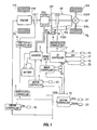
- FIG. 1 is an overall system diagram showing a hybrid vehicle according to an embodiment.
- FIG. 2 is a control block diagram showing arithmetic processings performed by a central controller.
- FIG. 3 is a travel mode selection map used in performing a mode selection processing in the central controller.
- FIG. 4 is a flow chart showing the flow of arithmetic processings performed by an AT controller.
- FIG. 5A is a map used in specifying a rotational speed of a pump motor.
- FIG. 5B is a map used in specifying a torque of the pump motor.
- FIG. 6A is a map used in specifying the rotational speed of the pump motor.
- FIG. 6B is a map used in specifying the torque of the pump motor.
- FIG. 1 is an overall system diagram showing a rear-wheel drive hybrid vehicle (an example of a hybrid vehicle) according to this embodiment.
- a drive system of the hybrid vehicle includes, as shown in FIG. 1 , an engine Eng, a flywheel FW, a first clutch CL1, a motor generator MG, an automatic transmission AT, a second clutch CL2, a propeller shaft PS, a differential DF, a left drive shaft DSL, a right drive shaft DSR. a left rear wheel RL (drive wheel), a right rear wheel RR (drive wheel), and a mechanical oil pump OP (mechanical oil pump).
- the engine Eng is a gasoline engine or a diesel engine and an engine start control, an engine stop control and a valve opening control for a throttle valve are executed based on engine control commands from an engine controller 1.
- the flywheel FW is provided on an engine output shaft.
- the first clutch CL1 is a clutch interposed between the engine Eng and the motor generator MG and released by supplying hydraulic oil, and engagement and release thereof including slip engagement and slip release are controlled by a first clutch control hydraulic pressure produced by a first clutch hydraulic unit 6 based on a first clutch control command from a first clutch controller 5.
- the motor generator MG is a synchronous motor generator in which a permanent magnet is embedded in a rotor and a stator coil is wound around a stator, and controlled by applying a three-phase alternating current produced by an inverter 3 based on a control command from a motor controller 2.
- This motor generator MG can operate as an electric motor which is driven and rotated by the supply of power from a battery 4 (hereinafter, this state is called powering) and can also function as a generator for producing an electromotive force at the opposite ends of the stator coil and charge the battery 4 when the rotor receives rotational energy from the engine Eng and the left and right rear wheels RL, RR (hereinafter, this state is called regeneration).
- the rotor of this motor generator MG is connected to an input shaft of the automatic transmission AT via a damper.
- the automatic transmission AT is, for example, a stepped transmission which automatically shifts stepped gear positions such as seven forward speeds and one reverse speed in accordance with a vehicle speed, an accelerator pedal opening and the like, and an output shaft thereof is connected to the left and right rear wheels RL, RR via the propeller shaft PS, the differential DF, the left drive shaft DSL and the right drive shaft DSR
- the second clutch CL2 is a clutch interposed between the motor generator MG and the left and right rear wheels RL, RR and engaged by supplying hydraulic oil, and engagement and release thereof including slip engagement and slip release are controlled by a control hydraulic pressure produced by a second clutch hydraulic unit 8 based on a second clutch control command from an AT controller 7.
- This second clutch CL2 is not newly added as a special clutch.
- an optimal clutch or brake arranged on a torque transmission path is selected. For example, a wet multiple disc clutch or a wet multiple disc brake capable of continuously controlling an oil flow rate and a hydraulic pressure using a proportional solenoid can be used.
- the first and second clutch hydraulic units 6, 8 are built in a hydraulic pressure control valve unit CVU attached to the automatic transmission AT. Further, this hydraulic pressure control valve unit CVU is provided with an electrical oil pump EP. An internal gear pump, an external gear pump, a vane pump or the like that produces a discharge pressure using an electrical pump motor EPM as a power source is adopted as the electrical oil pump EP. Discharge oil from this electrical oil pump EP is supplied to the first and second clutch hydraulic units 6, 8.
- the pump motor EPM is a synchronous motor in which a permanent magnet M (hereinafter, referred to as a "motor magnet”) is embedded in a rotor and a stator coil is wound around a stator, and controlled by applying a three-phase alternating current produced by the inventor 3 based on a control command from the motor controller 2 similar to the motor generator MG.
- a permanent magnet M hereinafter, referred to as a "motor magnet”
- the mechanical oil pump OP is arranged between the motor generator MG and the second clutch CL2, and an internal gear pump, an external gear pump, a vane pump or the like that produces a discharge pressure using at least one of the engine Eng and the motor generator MG as a pump power source is adopted as such. Discharge oil from this mechanical oil pump OP is supplied to the first and second clutch hydraulic units 6, 8.
- the drive system of this hybrid vehicle has two travel modes, i.e. a hybrid travel mode (hereinafter, referred to as a "HEV mode”) in which the vehicle travels using the engine Eng and the motor generator MG as power sources by engaging the first clutch CL1 and an electric vehicle travel mode (hereinafter, referred to as an "EV mode") in which the vehicle travels using only the motor generator MG as a power source by releasing the first clutch CL1.
- HEV-to-EV transition mode is set when a mode switch from the HEV mode to the EV mode is instructed
- an EV-to-HEV transition mode is set when a mode switch from the EV mode to the HEV mode is instructed.
- the control system of the hybrid vehicle includes, as shown in FIG. 1 , the engine controller 1, the motor controller 2, the inverter 3, the battery 4, the first clutch controller 5, the first clutch hydraulic unit 6, the AT controller 7, the second clutch hydraulic unit 8, a brake controller 9 and a central controller 10.
- the engine controller 1, the motor controller 2, the first clutch controller 5, the AT controller 7, the brake controller 9 and the central controller 10 are connected via a CAN communication line 11 which enables mutual information exchange.
- the engine controller 1 To the engine controller 1 are input an engine rotation speed Ne detected by an engine rotation speed sensor 12, a target engine torque command from the central controller 10 and other necessary information.
- the engine controller 1 outputs a command to control an engine operating point (Ne, Te) to a throttle valve actuator or the like of the engine Eng.
- the motor controller 2 To the motor controller 2 are input a rotor rotational position of the motor generator MG detected by a resolver 13, a target MG torque command and a target MG rotation speed command from the central controller 10 and other necessary information.
- the motor controller 2 outputs a command to control a motor operating point (Nm, Tm) of the motor generator MG to the inverter 3.
- This motor controller 2 monitors a battery SOC indicating a charged state of the battery 4 and this battery SOC information is used in control information of the motor generator MG and supplied to the central controller 10 via the CAN communication line 11.
- the first clutch controller 5 To the first clutch controller 5 are input a target CL1 torque command from the central controller 10 and other necessary information.
- the first clutch controller 5 outputs a command to control the engagement and release of the first clutch CL1 to the first clutch hydraulic unit 6 in the hydraulic pressure control valve unit CVU.
- the AT controller 7 To the AT controller 7 is input information from an accelerator pedal opening sensor 16, a vehicle speed sensor 17 and a second clutch hydraulic sensor 18.
- the AT controller 7 searches an optimal gear position based on a position in a shift map where an operating point determined by an accelerator pedal opening APO and a vehicle speed VSP is present, and outputs a gear position control command to achieve the searched gear position to the control valve unit CVU.
- the shift map is a map in which an upshift line and a downshift line corresponding to the acceleration pedal opening and the vehicle speed are written.
- the AT controller 7 reads a target engine torque command, a target MG torque command and a target mode from the central controller 10 and outputs a line pressure control command to control a line pressure of the hydraulic oil, thereby controlling a line pressure produced by the control valve unit CVU.
- the AT controller 7 executes a second clutch control to output a command to control the engagement and release of the second clutch CL2 to the second clutch hydraulic unit 8 in the hydraulic pressure control valve unit CVU. Further, the AT controller 7 receives temperature information of oil (ATF) used to lubricate the automatic transmission AT from an oil temperature sensor 23 and controls the pump motor EPM by outputting a motor torque command value.
- ATF temperature information of oil
- a regenerative cooperative control command from the central controller 10 and other necessary information.
- the brake controller 9 executes a regenerative cooperative brake control to compensate for a deficiency by mechanical braking forces (fluid pressure braking force and motor braking force) if it is insufficient when only a regenerative braking force is given for a required braking force required for a brake stroke BS.
- the central controller 10 has a function of managing consumption energy of the entire vehicle and causing the vehicle to travel with maximum efficiency.
- To the central controller 10 are input information from a motor rotation speed sensor 21 for detecting a motor rotation speed Nm, a second clutch output rotation speed sensor for detecting a second clutch output rotation speed N2out and the like and necessary information via the CAN communication line 11.
- the central controller 10 outputs a target engine torque command to the engine controller 1, a target MG torque command and a target MG rotation speed command to the motor controller 2, a target CL1 torque command to the first clutch controller 5, a target CL2 torque command to the AT controller 7 and a regenerative cooperative control command to the brake controller 9.
- FIG. 2 is a control block diagram showing arithmetic processings performed by the central controller 10 of the hybrid vehicle according to this embodiment
- FIG. 3 is a graph showing an EV-HEV selection map used in performing a mode selection processing in the central controller 10 of the hybrid vehicle. The arithmetic processings performed by the central controller 10 are described below with reference to FIGS. 2 and 3 .
- the central controller 10 includes a target drive force calculating unit 100, a mode selecting unit 200, a target charge/discharge calculating unit 300 and an operating point commanding unit 400.
- a target drive force tFoO is calculated from the accelerator pedal opening APO and the vehicle speed VSP using a target drive force map.
- the "EV mode” or the “HEV mode” is selected as a target travel mode from the accelerator pedal opening APO and the vehicle speed VSP using the EV-HEV selection map shown in FIG. 3 . If the battery SOC is a predetermined value or lower, the "HEV mode" is forcibly set as the target travel mode.
- target charge/discharge power tP is calculated from the battery SOC using a target charge/discharge amount map.
- a target engine torque, a target MG torque, a target MG rotation speed, a target CL1 torque and a target CL2 torque are calculated as operating-point achieving targets based on the accelerator pedal opening APO, the target drive force tFoO, the target travel mode, the vehicle speed VSP, the target charge/discharge power tP and the like.
- a target engine torque command, a target MG torque command, a target MG rotation speed command, a target CL1 torque command and a target CL2 torque command are output to the respective controllers 1, 2, 5 and 7 via the CAN communication line 11.
- the drive force of the engine Eng is suddenly transmitted to the drive wheels to cause a shock associated with a torque variation if the second clutch CL2 is switched from the released state to the engaged state when the vehicle starts in the HEV mode.
- the second clutch CL2 is controlled to be in a slip engagement state only for a predetermined period after the start (hereinafter, this control is referred to as a "WSC control"). That is, a drive force variation is absorbed by slip of the second clutch CL2.
- the second clutch CL2 Since the second clutch CL2 is held in a slip state during the above WSC control, the amount of oil supplied to the second clutch CL2 needs to be increased for lubrication and cooling. Accordingly, when oil temperature is high, the electrical oil pump EP is actuated in addition to the already actuated mechanical oil pump OP.
- the temperature of the pump motor EPM that drives the electrical oil pump EP increases due to high oil temperature and also increases due to self-heat generation by the drive of the pump motor EPM. This is accompanied by a temperature increase of the motor magnet M provided in the pump motor EPM.
- a temperature increase of the motor magnet M provided in the pump motor EPM When the temperature of the motor magnet M exceeds a predetermined demagnetization limit temperature, a magnetic force is reduced and, even if being cooled thereafter, the magnetic force is not restored. This causes the performance of the electrical oil pump EP to be reduced.
- the AT controller 7 executes the following control.
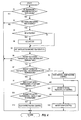
- FIG. 4 is a flow chart showing the flow of a control process of the pump motor EPM performed by the AT controller 7. This process is repeatedly performed at every interval of a very short time (e.g. 10 ms).
- Step S1 the AT controller 7 determines whether or not the oil temperature is higher than the demagnetization limit temperature.
- the process proceeds to Step S2 in the case of YES in determination, and ends in the case of NO.
- the oil temperature is the temperature of oil used for lubrication of the second clutch CL2 and, in this embodiment, the temperature of ATF used for lubrication of the automatic transmission AT.
- the demagnetization limit temperature e.g. 107°C
- Step S2 the AT controller 7 determines whether or not the travel mode of the vehicle is the HEV mode and the WSC control is being executed. The process proceeds to Step S3 in the case of YES in determination, and ends in the case of NO.
- Step S3 the AT controller 7 determines whether or not the electrical oil pump EP is being actuated. The process proceeds to Step S4 in the case of YES in determination, and proceeds to Step S5 in the case of NO.
- Step S4 the AT controller 7 actuates the electrical oil pump EP and advances the process to Step S5.
- Step S5 the AT controller 7 estimates the temperature of the motor magnet M and advances the process to Step S6.
- the temperature of the motor magnet M is calculated by adding a temperature increase caused by self-heat generation of the pump motor EPM to the present oil temperature.
- the temperature increase caused by self-heat generation of the pump motor EPM is calculated based on a map showing a relationship between the torque and rotation speed of the pump motor EPM and a heat generation amount, and this map is stored in the AT controller 7 beforehand.
- Step S6 the AT controller 7 determines whether or not the estimated temperature of the motor magnet M is higher than a first restrictive temperature.
- the process proceeds to Step S7 in the case of YES in determination, and ends in the case of NO.
- the first restrictive temperature is set around the maximum temperature (e.g. 106°C) at which the motor magnet M is not demagnetized.
- Step S7 the AT controller 7 determines whether or not the estimated temperature of the motor magnet M is higher than a second restrictive temperature.
- the process proceeds to Step S9 in the case of YES in determination, and proceeds to Step S8 in the case of NO.
- the second restrictive temperature is set at a temperature (e.g. 120°C) at which the motor magnet M is possibly demagnetized and which is higher than the first restrictive temperature.
- Step S8 the AT controller 7 executes a first high oil temperature control. This control is described later.
- Step S9 the AT controller 7 determines whether or not the estimated temperature of the motor magnet M is higher than a first limit temperature.
- the process proceeds to Step S11 in the case of YES in determination, and proceeds to Step S10 in the case of NO.
- the first limit temperature is a temperature (e.g. 160°C) at which the motor magnet M is possibly demagnetized and which is higher than the second restrictive temperature.
- Step S10 the AT controller 7 executes a second high oil temperature control. This control is described later.
- Step S11 the AT controller 7 determines whether or not the estimated temperature of the motor magnet M is higher than a second limit temperature.
- the process proceeds to Step S13 in the case of YES in determination, and proceeds to Step S12 in the case of NO.
- the second limit temperature is a temperature (e.g. 180°C) at which the motor magnet M is possibly demagnetized and which is higher than the first limit temperature.
- the AT controller 7 executes a motor stop control in Step S12 and executes a clutch protection control in Step S 13.
- FIGS. 5A and 5B are maps which specify a relationship between the oil temperature and the rotation speed and torque of the pump motor EPM.
- FIGS. 6A and 6B are maps which specify a relationship between the estimated temperature of the motor magnet M and the rotation speed and torque of the pump motor EPM.
- the torque and rotation speed of the pump motor EPM are set based on FIGS. 5A and 5B until the oil temperature is determined to be higher than the demagnetization limit temperature in Step S1, and set based on FIGS. 6A and 6B according to the temperature of the motor magnet M after the oil temperature exceeds the demagnetization limit temperature.
- the pump motor EPM is torque-controlled according to the oil temperature. Since the viscosity of the oil is reduced as the oil temperature increases, the torque is reduced by that much ( FIG. 5B ). Further, since the rotation speed of the pump motor EPM changes according to a load, an upper limit value and a lower limit value of the rotation speed are set and the rotation speed of the pump motor EPM is so controlled as to fall within a range between the both limit values to prevent step-out ( FIG. 5A ). Since an oil leak amount increases as the oil temperature increases, the upper and lower limit values are increased with an increase in the oil temperature to ensure an oil amount.
- the actuation of the pump motor EPM has been stopped to prevent demagnetization of the motor magnet M if the oil temperature exceeds the demagnetization limit temperature.
- the pump motor EPM is not immediately stopped and controlled as follows according to the estimated temperature of the motor magnet M even if the oil temperature is determined to have exceeded the demagnetization limit temperature in Step S1.
- Step S8 performed when the estimated temperature of the motor magnet M is higher than the first restrictive temperature and equal to or lower than the second restrictive temperature, a torque command value of the pump motor EPM is more restricted (reduced) than in normal time as the first high oil temperature control.
- a restriction amount is set with reference to the map of FIG. 6B so that the higher the estimated temperature of the motor magnet M, the lower the torque. Further, since the rotation speed also decreases with a decrease in the torque command value at this time, the lower limit value of the rotation speed is reduced ( FIG. 6A ).
- an interval of a retry performed when the pump motor EPM loses steps is set to be longer than in normal time.
- step-out is constantly monitored and a return is made by resetting a command value to the pump motor EPM once in the case of step-out.
- the retry interval is set to be longer than in normal time to prioritize a reduction of a heat generation amount over the return from the step-out. In this way, the heat generation amount of the pump motor EPM is suppressed.
- Step S10 performed when the estimated temperature of the motor magnet M is higher than the second restrictive temperature and equal to or lower than the first limit temperature, the torque command value of the pump motor EPM is further restricted (reduced) than in the first high oil temperature control as the second high oil temperature control.
- a restriction amount is set with reference to the map of FIG. 6B so that the higher the estimated temperature of the motor magnet M, the lower the torque. Further, since the rotation speed also decreases with a decrease in the torque command value at this time, the lower limit value of the rotation speed is reduced ( FIG. 6A ).
- the interval of the retry performed when the pump motor EPM loses steps is set to be longer than in normal time. In this way, the heat generation amount of the pump motor EPM is suppressed.
- Step S12 performed when the estimated temperature of the motor magnet M is higher than the first limit temperature and equal to or lower than the second limit temperature, the torque command value of the pump motor EPM is set to zero as the motor stop control ( FIG. 6B ). In this way, the actuation of the pump motor EPM is stopped.
- Step S13 performed when the estimated temperature of the motor magnet M is higher than the second limit temperature, torque restriction of the pump motor EPM is lifted and a maximum torque command value in normal time is set as clutch protection control ( FIG. 6B ).
- the lower limit value of the rotation speed is increased ( FIG. 6A ).
- the clutch protection control is a control to prioritize lubrication and cooling of the second clutch CL2 over prevention of demagnetization of the motor magnet M.
- the interval of the retry performed when the pump motor EPM loses steps is set to be longer than in normal time similar to the first high oil temperature control. In this way, the heat generation amount of the pump motor EPM is suppressed.
- the output of the pump motor EPM is maximized and securement of the lubrication flow rate of the second clutch CL2 is prioritized over prevention of demagnetization of the motor magnet M by the clutch protection control.
- the second clutch CL2 when the oil temperature is high can be prevented.
- the temperature of the motor magnet M is estimated and the output torque and lower limit rotation speed of the pump motor EPM are restricted and reduced when the estimated temperature exceeds the first restrictive temperature while the vehicle is traveling in the HEV mode and the WSC control is being executed.
- the motor magnet M reaches the demagnetization temperature to be demagnetized even when the oil temperature is high and the operating range of the electrical oil pump EP can be enlarged to a higher temperature side. Therefore, a higher lubrication flow rate of the second clutch CL2 particularly when the oil temperature is high can be ensured.
- the output of the pump motor EPM is controlled based on the estimated temperature of the motor magnet M, it can be prevented that the output of the pump motor EPM is unnecessarily restricted and the second clutch CL2 can be more reliably lubricated when the oil temperature is high and the temperature of the motor magnet M is lower than the oil temperature.
- the output torque and lower limit rotation speed of the pump motor EPM are reduced by the first high oil temperature control and, in addition, more reduced than in the first high oil temperature control by the second high oil temperature control when the estimated temperature exceeds the second restrictive temperature.
- a temperature increase of the motor magnet M can be suppressed by reducing the torque and rotation speed of the pump motor EPM according to an increase in the oil temperature. Therefore, the pump motor EPM can be actuated up to the vicinity of the demagnetization limit and the second clutch CL2 can be more reliably lubricated by ensuring the amount of oil discharged from the electrical oil pump EP even when the oil temperature is high.
Applications Claiming Priority (1)
| Application Number | Priority Date | Filing Date | Title |
|---|---|---|---|
| JP2010245992A JP5786216B2 (ja) | 2010-11-02 | 2010-11-02 | ハイブリッド車両 |
Publications (3)
| Publication Number | Publication Date |
|---|---|
| EP2447121A2 true EP2447121A2 (fr) | 2012-05-02 |
| EP2447121A3 EP2447121A3 (fr) | 2017-08-23 |
| EP2447121B1 EP2447121B1 (fr) | 2018-07-18 |
Family
ID=44992451
Family Applications (1)
| Application Number | Title | Priority Date | Filing Date |
|---|---|---|---|
| EP11008598.2A Active EP2447121B1 (fr) | 2010-11-02 | 2011-10-26 | Véhicule hybride et son procédé de contrôle |
Country Status (5)
| Country | Link |
|---|---|
| US (1) | US8480537B2 (fr) |
| EP (1) | EP2447121B1 (fr) |
| JP (1) | JP5786216B2 (fr) |
| KR (1) | KR101341185B1 (fr) |
| CN (1) | CN102463985B (fr) |
Cited By (4)
| Publication number | Priority date | Publication date | Assignee | Title |
|---|---|---|---|---|
| WO2015104627A1 (fr) * | 2014-01-09 | 2015-07-16 | Toyota Jidosha Kabushiki Kaisha | Dispositif de commande pour véhicule |
| EP2933620A3 (fr) * | 2014-04-14 | 2015-11-04 | Hyundai Motor Company | Système et procédé pour estimer la température de rotor d'un moteur |
| EP3109995A4 (fr) * | 2014-02-21 | 2017-12-20 | Hitachi Automotive Systems, Ltd. | Dispositif de commande et procédé de commande d'actionneur |
| WO2020016491A1 (fr) | 2018-07-19 | 2020-01-23 | Psa Automobiles Sa | Procede de pilotage d'un groupe moto-propulseur comprenant un alterno-demarreur |
Families Citing this family (27)
| Publication number | Priority date | Publication date | Assignee | Title |
|---|---|---|---|---|
| DE102007041569A1 (de) * | 2007-09-01 | 2009-03-05 | Zf Friedrichshafen Ag | Verfahren zum Steuern und/oder Regeln einer Hybridantriebsanordnung |
| DE102007055785A1 (de) * | 2007-12-13 | 2009-06-18 | Zf Friedrichshafen Ag | Verfahren und Vorrichtung zur Steuerung eines Kriechbetriebes eines Fahrzeuges mit einem Hybridantrieb |
| JP5436532B2 (ja) * | 2008-03-27 | 2014-03-05 | マクソン モーター アーゲー | 相互作用タスク及び高速動作に適する二重差動型セミアクティブアクチュエータ |
| US10479184B2 (en) * | 2010-09-30 | 2019-11-19 | Evaos, Inc. | Auxiliary electric drive system and vehicle using same |
| CN103338959B (zh) * | 2011-01-28 | 2016-02-10 | 日产自动车株式会社 | 混合动力车辆的控制装置 |
| KR101505349B1 (ko) * | 2011-01-28 | 2015-03-23 | 쟈트코 가부시키가이샤 | 하이브리드 차량의 제어 장치 |
| CN102691650B (zh) * | 2011-03-22 | 2015-07-01 | 日立汽车系统株式会社 | 电动油泵的控制装置和控制方法 |
| KR101339247B1 (ko) * | 2011-11-30 | 2014-01-06 | 기아자동차 주식회사 | 하이브리드 자동차의 배터리 충전 방법 및 상기 방법을 사용하는 하이브리드 자동차 |
| KR101826536B1 (ko) * | 2012-08-07 | 2018-02-07 | 현대자동차 주식회사 | 차량의 아이들 스톱 제어 방법 및 장치 |
| US9020740B2 (en) * | 2012-10-15 | 2015-04-28 | GM Global Technology Operations LLC | Fluid pump speed control |
| JP5635581B2 (ja) * | 2012-11-02 | 2014-12-03 | 本田技研工業株式会社 | 回転電機の磁石温度推定装置及び磁石温度推定方法 |
| KR20140059614A (ko) * | 2012-11-08 | 2014-05-16 | 현대자동차주식회사 | 하이브리드 차량의 클러치 유체의 웜 업 제어 방법 및 시스템 |
| US9604629B2 (en) * | 2012-12-12 | 2017-03-28 | Toyota Jidosha Kabushiki Kaisha | Hybrid vehicle control device |
| JP6036277B2 (ja) * | 2012-12-25 | 2016-11-30 | アイシン・エィ・ダブリュ株式会社 | 車両用伝動装置 |
| JP6106265B2 (ja) * | 2013-03-21 | 2017-03-29 | ジヤトコ株式会社 | 車両制御装置および車両の制御方法 |
| CN105026233A (zh) * | 2013-03-29 | 2015-11-04 | 爱信艾达株式会社 | 供油装置 |
| US9352738B2 (en) | 2013-07-31 | 2016-05-31 | Allison Transmission, Inc. | Dual clutch powertrain architecture |
| KR101500403B1 (ko) | 2013-12-26 | 2015-03-09 | 현대자동차 주식회사 | 하이브리드 차량의 클러치 슬립 제어 장치 및 방법 |
| US9481256B2 (en) * | 2014-01-30 | 2016-11-01 | Amp Electric Vehicles Inc. | Onboard generator drive system for electric vehicles |
| US9738265B2 (en) * | 2014-03-24 | 2017-08-22 | Ford Global Technologies, Llc | System and method for determining engine disconnect clutch torque |
| KR101795586B1 (ko) | 2015-10-06 | 2017-11-09 | 현대 파워텍 주식회사 | 자동 변속기의 오일펌프 구동장치 및 그 방법 |
| JP6332298B2 (ja) * | 2016-02-12 | 2018-05-30 | トヨタ自動車株式会社 | 車両 |
| KR101855784B1 (ko) | 2016-11-09 | 2018-05-09 | 현대자동차 주식회사 | 차량용 모터 제어 장치 및 방법 |
| JP6885148B2 (ja) * | 2017-03-29 | 2021-06-09 | トヨタ自動車株式会社 | 電動機の制御装置 |
| DE102017214787A1 (de) * | 2017-08-23 | 2019-02-28 | Bayerische Motoren Werke Aktiengesellschaft | Impulsstart in einem Hybrid-Antriebsstrang |
| DE102019207254A1 (de) * | 2019-05-17 | 2020-11-19 | Zf Friedrichshafen Ag | Verfahren und Steuergerät zum Betreiben eines Antriebsstrangs eines Kraftfahrzeugs |
| JP7404916B2 (ja) * | 2020-02-14 | 2023-12-26 | マツダ株式会社 | 移動体の制御装置 |
Citations (2)
| Publication number | Priority date | Publication date | Assignee | Title |
|---|---|---|---|---|
| JP2007015679A (ja) | 2005-06-06 | 2007-01-25 | Nissan Motor Co Ltd | ハイブリッド車両のオイルポンプ駆動制御装置 |
| JP2010245992A (ja) | 2009-04-09 | 2010-10-28 | Yamaha Corp | ハウリング防止装置 |
Family Cites Families (13)
| Publication number | Priority date | Publication date | Assignee | Title |
|---|---|---|---|---|
| JP3893778B2 (ja) * | 1998-11-09 | 2007-03-14 | トヨタ自動車株式会社 | ロックアップクラッチ制御装置 |
| JP4576714B2 (ja) | 2000-12-28 | 2010-11-10 | アイシン・エィ・ダブリュ株式会社 | オイルポンプの駆動制御装置 |
| JP3915698B2 (ja) * | 2002-12-27 | 2007-05-16 | アイシン・エィ・ダブリュ株式会社 | ハイブリッド車輌の制御装置 |
| WO2007055192A1 (fr) * | 2005-11-09 | 2007-05-18 | Kabushiki Kaisha Toshiba | Rotor pour machine rotative electrique et machine rotative electrique |
| JP2007186154A (ja) * | 2006-01-16 | 2007-07-26 | Toyota Motor Corp | ハイブリッド車両の制御装置およびそれを搭載するハイブリッド車両 |
| JP4530999B2 (ja) | 2006-02-23 | 2010-08-25 | 本田技研工業株式会社 | ハイブリッド車両の制御装置 |
| JP4421603B2 (ja) * | 2006-12-01 | 2010-02-24 | 本田技研工業株式会社 | モータ制御方法およびモータ制御装置 |
| JP5252171B2 (ja) * | 2007-09-19 | 2013-07-31 | アイシン・エィ・ダブリュ株式会社 | 車両用制御装置 |
| JP2009083583A (ja) * | 2007-09-28 | 2009-04-23 | Toyota Motor Corp | 車両の制御装置 |
| JP5163939B2 (ja) * | 2007-10-23 | 2013-03-13 | アイシン・エィ・ダブリュ株式会社 | 車両用制御装置 |
| JP5125727B2 (ja) * | 2008-04-24 | 2013-01-23 | 日産自動車株式会社 | ハイブリッド車両の発進制御装置 |
| JP4685146B2 (ja) | 2008-09-24 | 2011-05-18 | ジヤトコ株式会社 | ハイブリッド車両の制御装置 |
| JP5417873B2 (ja) * | 2009-02-09 | 2014-02-19 | 日産自動車株式会社 | ハイブリッド車両の制御装置 |
-
2010
- 2010-11-02 JP JP2010245992A patent/JP5786216B2/ja active Active
-
2011
- 2011-10-26 EP EP11008598.2A patent/EP2447121B1/fr active Active
- 2011-10-26 US US13/281,891 patent/US8480537B2/en active Active
- 2011-10-27 CN CN201110331575.8A patent/CN102463985B/zh active Active
- 2011-11-01 KR KR1020110112814A patent/KR101341185B1/ko active IP Right Grant
Patent Citations (2)
| Publication number | Priority date | Publication date | Assignee | Title |
|---|---|---|---|---|
| JP2007015679A (ja) | 2005-06-06 | 2007-01-25 | Nissan Motor Co Ltd | ハイブリッド車両のオイルポンプ駆動制御装置 |
| JP2010245992A (ja) | 2009-04-09 | 2010-10-28 | Yamaha Corp | ハウリング防止装置 |
Cited By (5)
| Publication number | Priority date | Publication date | Assignee | Title |
|---|---|---|---|---|
| WO2015104627A1 (fr) * | 2014-01-09 | 2015-07-16 | Toyota Jidosha Kabushiki Kaisha | Dispositif de commande pour véhicule |
| EP3109995A4 (fr) * | 2014-02-21 | 2017-12-20 | Hitachi Automotive Systems, Ltd. | Dispositif de commande et procédé de commande d'actionneur |
| EP2933620A3 (fr) * | 2014-04-14 | 2015-11-04 | Hyundai Motor Company | Système et procédé pour estimer la température de rotor d'un moteur |
| US9584058B2 (en) | 2014-04-14 | 2017-02-28 | Hyundai Motor Company | System and method for estimating temperature of rotor of motor |
| WO2020016491A1 (fr) | 2018-07-19 | 2020-01-23 | Psa Automobiles Sa | Procede de pilotage d'un groupe moto-propulseur comprenant un alterno-demarreur |
Also Published As
| Publication number | Publication date |
|---|---|
| JP2012096659A (ja) | 2012-05-24 |
| JP5786216B2 (ja) | 2015-09-30 |
| US20120108385A1 (en) | 2012-05-03 |
| KR101341185B1 (ko) | 2013-12-12 |
| KR20120046699A (ko) | 2012-05-10 |
| US8480537B2 (en) | 2013-07-09 |
| EP2447121A3 (fr) | 2017-08-23 |
| CN102463985A (zh) | 2012-05-23 |
| EP2447121B1 (fr) | 2018-07-18 |
| CN102463985B (zh) | 2014-10-15 |
Similar Documents
| Publication | Publication Date | Title |
|---|---|---|
| EP2447121B1 (fr) | Véhicule hybride et son procédé de contrôle | |
| KR100837903B1 (ko) | 하이브리드 차량의 엔진 시동 제어 장치 | |
| JP5419627B2 (ja) | ハイブリッド車両の制御装置 | |
| JP5103992B2 (ja) | ハイブリッド車両の制御装置及びハイブリッド車両の制御方法。 | |
| JP5252087B2 (ja) | ハイブリッド車両の制御装置 | |
| EP1939059B1 (fr) | Système de contrôle de changement de mode pour véhicule hybride | |
| KR101696586B1 (ko) | 차량의 제어 장치 | |
| EP2447122A2 (fr) | Appareil de contrôle pour véhicule et son procédé de contrôle | |
| EP2639130A1 (fr) | Dispositif de commande de véhicule hybride | |
| EP2727786B1 (fr) | Dispositif pour commander un véhicule hybride | |
| KR20100109421A (ko) | 하이브리드 차량의 제어 장치 | |
| EP2727785B1 (fr) | Dispositif de commande de véhicule | |
| JP2010155590A (ja) | ハイブリッド車両の発進制御装置。 | |
| JP6485292B2 (ja) | 電動車両の電力制御方法および電力制御装置 | |
| JP4935797B2 (ja) | 電動車の制御装置 | |
| US9321456B2 (en) | Hybrid vehicle control device | |
| JP2010188776A (ja) | ハイブリッド車両の制御装置 | |
| JP5556580B2 (ja) | ハイブリッド車両の制御装置 | |
| JP2012092975A (ja) | 自動変速機 | |
| JP5550524B2 (ja) | 自動変速機 | |
| JP2012092939A5 (fr) |
Legal Events
| Date | Code | Title | Description |
|---|---|---|---|
| PUAI | Public reference made under article 153(3) epc to a published international application that has entered the european phase |
Free format text: ORIGINAL CODE: 0009012 |
|
| AK | Designated contracting states |
Kind code of ref document: A2 Designated state(s): AL AT BE BG CH CY CZ DE DK EE ES FI FR GB GR HR HU IE IS IT LI LT LU LV MC MK MT NL NO PL PT RO RS SE SI SK SM TR |
|
| AX | Request for extension of the european patent |
Extension state: BA ME |
|
| RAP1 | Party data changed (applicant data changed or rights of an application transferred) |
Owner name: JATCO LTD Owner name: NISSAN MOTOR CO., LTD. |
|
| PUAL | Search report despatched |
Free format text: ORIGINAL CODE: 0009013 |
|
| AK | Designated contracting states |
Kind code of ref document: A3 Designated state(s): AL AT BE BG CH CY CZ DE DK EE ES FI FR GB GR HR HU IE IS IT LI LT LU LV MC MK MT NL NO PL PT RO RS SE SI SK SM TR |
|
| AX | Request for extension of the european patent |
Extension state: BA ME |
|
| RIC1 | Information provided on ipc code assigned before grant |
Ipc: B60W 10/02 20060101ALI20170717BHEP Ipc: F16H 61/00 20060101ALI20170717BHEP Ipc: B60W 10/30 20060101ALI20170717BHEP Ipc: B60K 6/48 20071001ALI20170717BHEP Ipc: B60W 10/08 20060101ALI20170717BHEP Ipc: B60W 30/186 20120101ALI20170717BHEP Ipc: B60W 20/00 20160101AFI20170717BHEP |
|
| 17P | Request for examination filed |
Effective date: 20170927 |
|
| RBV | Designated contracting states (corrected) |
Designated state(s): AL AT BE BG CH CY CZ DE DK EE ES FI FR GB GR HR HU IE IS IT LI LT LU LV MC MK MT NL NO PL PT RO RS SE SI SK SM TR |
|
| REG | Reference to a national code |
Ref country code: DE Ref legal event code: R079 Ref document number: 602011050085 Country of ref document: DE Free format text: PREVIOUS MAIN CLASS: B60W0010080000 Ipc: B60W0030180000 |
|
| GRAP | Despatch of communication of intention to grant a patent |
Free format text: ORIGINAL CODE: EPIDOSNIGR1 |
|
| RIC1 | Information provided on ipc code assigned before grant |
Ipc: B60W 30/186 20120101ALI20180129BHEP Ipc: B60W 10/08 20060101ALI20180129BHEP Ipc: B60W 10/30 20060101ALI20180129BHEP Ipc: B60K 6/48 20071001ALI20180129BHEP Ipc: B60W 10/02 20060101ALI20180129BHEP Ipc: B60W 20/00 20160101ALI20180129BHEP Ipc: B60W 30/18 20120101AFI20180129BHEP Ipc: F16H 61/00 20060101ALI20180129BHEP |
|
| INTG | Intention to grant announced |
Effective date: 20180308 |
|
| GRAS | Grant fee paid |
Free format text: ORIGINAL CODE: EPIDOSNIGR3 |
|
| GRAA | (expected) grant |
Free format text: ORIGINAL CODE: 0009210 |
|
| AK | Designated contracting states |
Kind code of ref document: B1 Designated state(s): AL AT BE BG CH CY CZ DE DK EE ES FI FR GB GR HR HU IE IS IT LI LT LU LV MC MK MT NL NO PL PT RO RS SE SI SK SM TR |
|
| REG | Reference to a national code |
Ref country code: GB Ref legal event code: FG4D |
|
| REG | Reference to a national code |
Ref country code: CH Ref legal event code: EP |
|
| REG | Reference to a national code |
Ref country code: IE Ref legal event code: FG4D |
|
| REG | Reference to a national code |
Ref country code: AT Ref legal event code: REF Ref document number: 1019007 Country of ref document: AT Kind code of ref document: T Effective date: 20180815 |
|
| REG | Reference to a national code |
Ref country code: DE Ref legal event code: R096 Ref document number: 602011050085 Country of ref document: DE |
|
| REG | Reference to a national code |
Ref country code: FR Ref legal event code: PLFP Year of fee payment: 8 |
|
| REG | Reference to a national code |
Ref country code: NL Ref legal event code: MP Effective date: 20180718 |
|
| REG | Reference to a national code |
Ref country code: LT Ref legal event code: MG4D |
|
| REG | Reference to a national code |
Ref country code: AT Ref legal event code: MK05 Ref document number: 1019007 Country of ref document: AT Kind code of ref document: T Effective date: 20180718 |
|
| PG25 | Lapsed in a contracting state [announced via postgrant information from national office to epo] |
Ref country code: NL Free format text: LAPSE BECAUSE OF FAILURE TO SUBMIT A TRANSLATION OF THE DESCRIPTION OR TO PAY THE FEE WITHIN THE PRESCRIBED TIME-LIMIT Effective date: 20180718 |
|
| PG25 | Lapsed in a contracting state [announced via postgrant information from national office to epo] |
Ref country code: FI Free format text: LAPSE BECAUSE OF FAILURE TO SUBMIT A TRANSLATION OF THE DESCRIPTION OR TO PAY THE FEE WITHIN THE PRESCRIBED TIME-LIMIT Effective date: 20180718 Ref country code: GR Free format text: LAPSE BECAUSE OF FAILURE TO SUBMIT A TRANSLATION OF THE DESCRIPTION OR TO PAY THE FEE WITHIN THE PRESCRIBED TIME-LIMIT Effective date: 20181019 Ref country code: SE Free format text: LAPSE BECAUSE OF FAILURE TO SUBMIT A TRANSLATION OF THE DESCRIPTION OR TO PAY THE FEE WITHIN THE PRESCRIBED TIME-LIMIT Effective date: 20180718 Ref country code: RS Free format text: LAPSE BECAUSE OF FAILURE TO SUBMIT A TRANSLATION OF THE DESCRIPTION OR TO PAY THE FEE WITHIN THE PRESCRIBED TIME-LIMIT Effective date: 20180718 Ref country code: IS Free format text: LAPSE BECAUSE OF FAILURE TO SUBMIT A TRANSLATION OF THE DESCRIPTION OR TO PAY THE FEE WITHIN THE PRESCRIBED TIME-LIMIT Effective date: 20181118 Ref country code: LT Free format text: LAPSE BECAUSE OF FAILURE TO SUBMIT A TRANSLATION OF THE DESCRIPTION OR TO PAY THE FEE WITHIN THE PRESCRIBED TIME-LIMIT Effective date: 20180718 Ref country code: AT Free format text: LAPSE BECAUSE OF FAILURE TO SUBMIT A TRANSLATION OF THE DESCRIPTION OR TO PAY THE FEE WITHIN THE PRESCRIBED TIME-LIMIT Effective date: 20180718 Ref country code: NO Free format text: LAPSE BECAUSE OF FAILURE TO SUBMIT A TRANSLATION OF THE DESCRIPTION OR TO PAY THE FEE WITHIN THE PRESCRIBED TIME-LIMIT Effective date: 20181018 Ref country code: PL Free format text: LAPSE BECAUSE OF FAILURE TO SUBMIT A TRANSLATION OF THE DESCRIPTION OR TO PAY THE FEE WITHIN THE PRESCRIBED TIME-LIMIT Effective date: 20180718 Ref country code: BG Free format text: LAPSE BECAUSE OF FAILURE TO SUBMIT A TRANSLATION OF THE DESCRIPTION OR TO PAY THE FEE WITHIN THE PRESCRIBED TIME-LIMIT Effective date: 20181018 |
|
| REG | Reference to a national code |
Ref country code: CH Ref legal event code: PK Free format text: BERICHTIGUNGEN |
|
| RIC2 | Information provided on ipc code assigned after grant |
Ipc: B60W 20/00 20160101ALI20180129BHEP Ipc: B60W 30/18 20120101AFI20180129BHEP Ipc: F16H 61/00 20060101ALI20180129BHEP Ipc: B60W 10/08 20060101ALI20180129BHEP Ipc: B60W 10/30 20060101ALI20180129BHEP Ipc: B60K 6/48 20071001ALI20180129BHEP Ipc: B60W 30/186 20120101ALI20180129BHEP Ipc: B60W 10/02 20060101ALI20180129BHEP |
|
| PG25 | Lapsed in a contracting state [announced via postgrant information from national office to epo] |
Ref country code: AL Free format text: LAPSE BECAUSE OF FAILURE TO SUBMIT A TRANSLATION OF THE DESCRIPTION OR TO PAY THE FEE WITHIN THE PRESCRIBED TIME-LIMIT Effective date: 20180718 Ref country code: ES Free format text: LAPSE BECAUSE OF FAILURE TO SUBMIT A TRANSLATION OF THE DESCRIPTION OR TO PAY THE FEE WITHIN THE PRESCRIBED TIME-LIMIT Effective date: 20180718 Ref country code: HR Free format text: LAPSE BECAUSE OF FAILURE TO SUBMIT A TRANSLATION OF THE DESCRIPTION OR TO PAY THE FEE WITHIN THE PRESCRIBED TIME-LIMIT Effective date: 20180718 Ref country code: LV Free format text: LAPSE BECAUSE OF FAILURE TO SUBMIT A TRANSLATION OF THE DESCRIPTION OR TO PAY THE FEE WITHIN THE PRESCRIBED TIME-LIMIT Effective date: 20180718 |
|
| PGFP | Annual fee paid to national office [announced via postgrant information from national office to epo] |
Ref country code: FR Payment date: 20181023 Year of fee payment: 8 |
|
| REG | Reference to a national code |
Ref country code: DE Ref legal event code: R097 Ref document number: 602011050085 Country of ref document: DE |
|
| PG25 | Lapsed in a contracting state [announced via postgrant information from national office to epo] |
Ref country code: EE Free format text: LAPSE BECAUSE OF FAILURE TO SUBMIT A TRANSLATION OF THE DESCRIPTION OR TO PAY THE FEE WITHIN THE PRESCRIBED TIME-LIMIT Effective date: 20180718 Ref country code: CZ Free format text: LAPSE BECAUSE OF FAILURE TO SUBMIT A TRANSLATION OF THE DESCRIPTION OR TO PAY THE FEE WITHIN THE PRESCRIBED TIME-LIMIT Effective date: 20180718 Ref country code: RO Free format text: LAPSE BECAUSE OF FAILURE TO SUBMIT A TRANSLATION OF THE DESCRIPTION OR TO PAY THE FEE WITHIN THE PRESCRIBED TIME-LIMIT Effective date: 20180718 Ref country code: IT Free format text: LAPSE BECAUSE OF FAILURE TO SUBMIT A TRANSLATION OF THE DESCRIPTION OR TO PAY THE FEE WITHIN THE PRESCRIBED TIME-LIMIT Effective date: 20180718 |
|
| PLBE | No opposition filed within time limit |
Free format text: ORIGINAL CODE: 0009261 |
|
| STAA | Information on the status of an ep patent application or granted ep patent |
Free format text: STATUS: NO OPPOSITION FILED WITHIN TIME LIMIT |
|
| PG25 | Lapsed in a contracting state [announced via postgrant information from national office to epo] |
Ref country code: SM Free format text: LAPSE BECAUSE OF FAILURE TO SUBMIT A TRANSLATION OF THE DESCRIPTION OR TO PAY THE FEE WITHIN THE PRESCRIBED TIME-LIMIT Effective date: 20180718 Ref country code: SK Free format text: LAPSE BECAUSE OF FAILURE TO SUBMIT A TRANSLATION OF THE DESCRIPTION OR TO PAY THE FEE WITHIN THE PRESCRIBED TIME-LIMIT Effective date: 20180718 Ref country code: DK Free format text: LAPSE BECAUSE OF FAILURE TO SUBMIT A TRANSLATION OF THE DESCRIPTION OR TO PAY THE FEE WITHIN THE PRESCRIBED TIME-LIMIT Effective date: 20180718 |
|
| REG | Reference to a national code |
Ref country code: CH Ref legal event code: PL |
|
| 26N | No opposition filed |
Effective date: 20190423 |
|
| GBPC | Gb: european patent ceased through non-payment of renewal fee |
Effective date: 20181026 |
|
| REG | Reference to a national code |
Ref country code: BE Ref legal event code: MM Effective date: 20181031 |
|
| PG25 | Lapsed in a contracting state [announced via postgrant information from national office to epo] |
Ref country code: LU Free format text: LAPSE BECAUSE OF NON-PAYMENT OF DUE FEES Effective date: 20181026 Ref country code: MC Free format text: LAPSE BECAUSE OF FAILURE TO SUBMIT A TRANSLATION OF THE DESCRIPTION OR TO PAY THE FEE WITHIN THE PRESCRIBED TIME-LIMIT Effective date: 20180718 |
|
| REG | Reference to a national code |
Ref country code: IE Ref legal event code: MM4A |
|
| PG25 | Lapsed in a contracting state [announced via postgrant information from national office to epo] |
Ref country code: BE Free format text: LAPSE BECAUSE OF NON-PAYMENT OF DUE FEES Effective date: 20181031 Ref country code: CH Free format text: LAPSE BECAUSE OF NON-PAYMENT OF DUE FEES Effective date: 20181031 Ref country code: SI Free format text: LAPSE BECAUSE OF FAILURE TO SUBMIT A TRANSLATION OF THE DESCRIPTION OR TO PAY THE FEE WITHIN THE PRESCRIBED TIME-LIMIT Effective date: 20180718 Ref country code: LI Free format text: LAPSE BECAUSE OF NON-PAYMENT OF DUE FEES Effective date: 20181031 |
|
| PG25 | Lapsed in a contracting state [announced via postgrant information from national office to epo] |
Ref country code: GB Free format text: LAPSE BECAUSE OF NON-PAYMENT OF DUE FEES Effective date: 20181026 Ref country code: IE Free format text: LAPSE BECAUSE OF NON-PAYMENT OF DUE FEES Effective date: 20181026 |
|
| PG25 | Lapsed in a contracting state [announced via postgrant information from national office to epo] |
Ref country code: MT Free format text: LAPSE BECAUSE OF NON-PAYMENT OF DUE FEES Effective date: 20181026 |
|
| PG25 | Lapsed in a contracting state [announced via postgrant information from national office to epo] |
Ref country code: TR Free format text: LAPSE BECAUSE OF FAILURE TO SUBMIT A TRANSLATION OF THE DESCRIPTION OR TO PAY THE FEE WITHIN THE PRESCRIBED TIME-LIMIT Effective date: 20180718 |
|
| PG25 | Lapsed in a contracting state [announced via postgrant information from national office to epo] |
Ref country code: PT Free format text: LAPSE BECAUSE OF FAILURE TO SUBMIT A TRANSLATION OF THE DESCRIPTION OR TO PAY THE FEE WITHIN THE PRESCRIBED TIME-LIMIT Effective date: 20180718 |
|
| PG25 | Lapsed in a contracting state [announced via postgrant information from national office to epo] |
Ref country code: MK Free format text: LAPSE BECAUSE OF NON-PAYMENT OF DUE FEES Effective date: 20180718 Ref country code: CY Free format text: LAPSE BECAUSE OF FAILURE TO SUBMIT A TRANSLATION OF THE DESCRIPTION OR TO PAY THE FEE WITHIN THE PRESCRIBED TIME-LIMIT Effective date: 20180718 Ref country code: HU Free format text: LAPSE BECAUSE OF FAILURE TO SUBMIT A TRANSLATION OF THE DESCRIPTION OR TO PAY THE FEE WITHIN THE PRESCRIBED TIME-LIMIT; INVALID AB INITIO Effective date: 20111026 |
|
| PG25 | Lapsed in a contracting state [announced via postgrant information from national office to epo] |
Ref country code: FR Free format text: LAPSE BECAUSE OF NON-PAYMENT OF DUE FEES Effective date: 20191031 |
|
| PGFP | Annual fee paid to national office [announced via postgrant information from national office to epo] |
Ref country code: DE Payment date: 20230830 Year of fee payment: 13 |