EP2446232B1 - Structure de débitmètre pour distributeur de boissons - Google Patents
Structure de débitmètre pour distributeur de boissons Download PDFInfo
- Publication number
- EP2446232B1 EP2446232B1 EP10725748.7A EP10725748A EP2446232B1 EP 2446232 B1 EP2446232 B1 EP 2446232B1 EP 10725748 A EP10725748 A EP 10725748A EP 2446232 B1 EP2446232 B1 EP 2446232B1
- Authority
- EP
- European Patent Office
- Prior art keywords
- flowmeter
- housing
- shaft
- cup
- cover body
- Prior art date
- Legal status (The legal status is an assumption and is not a legal conclusion. Google has not performed a legal analysis and makes no representation as to the accuracy of the status listed.)
- Active
Links
- 235000013361 beverage Nutrition 0.000 title claims description 24
- 239000007788 liquid Substances 0.000 claims description 21
- 239000000463 material Substances 0.000 claims description 20
- 238000002360 preparation method Methods 0.000 claims description 14
- 239000000945 filler Substances 0.000 claims description 9
- 239000011324 bead Substances 0.000 claims description 8
- 239000002131 composite material Substances 0.000 claims description 6
- 238000007789 sealing Methods 0.000 claims description 5
- 239000011521 glass Substances 0.000 claims description 3
- 230000003019 stabilising effect Effects 0.000 claims description 2
- XLYOFNOQVPJJNP-UHFFFAOYSA-N water Substances O XLYOFNOQVPJJNP-UHFFFAOYSA-N 0.000 description 10
- PXAGFNRKXSYIHU-UHFFFAOYSA-N 1,3-dichloro-2-(2,6-dichlorophenyl)benzene Chemical compound ClC1=CC=CC(Cl)=C1C1=C(Cl)C=CC=C1Cl PXAGFNRKXSYIHU-UHFFFAOYSA-N 0.000 description 8
- 235000016213 coffee Nutrition 0.000 description 7
- 235000013353 coffee beverage Nutrition 0.000 description 7
- 239000004615 ingredient Substances 0.000 description 7
- 229920006324 polyoxymethylene Polymers 0.000 description 6
- 238000005299 abrasion Methods 0.000 description 5
- 239000012530 fluid Substances 0.000 description 5
- 238000004519 manufacturing process Methods 0.000 description 5
- 238000000465 moulding Methods 0.000 description 5
- 239000010432 diamond Substances 0.000 description 4
- 238000010438 heat treatment Methods 0.000 description 4
- 244000269722 Thea sinensis Species 0.000 description 3
- 244000299461 Theobroma cacao Species 0.000 description 3
- 239000002775 capsule Substances 0.000 description 3
- 229910003460 diamond Inorganic materials 0.000 description 3
- 235000013305 food Nutrition 0.000 description 3
- 235000019219 chocolate Nutrition 0.000 description 2
- 238000001802 infusion Methods 0.000 description 2
- 235000013336 milk Nutrition 0.000 description 2
- 239000008267 milk Substances 0.000 description 2
- 210000004080 milk Anatomy 0.000 description 2
- 238000002156 mixing Methods 0.000 description 2
- 235000014347 soups Nutrition 0.000 description 2
- 235000013616 tea Nutrition 0.000 description 2
- 240000007154 Coffea arabica Species 0.000 description 1
- 239000004642 Polyimide Substances 0.000 description 1
- 235000005764 Theobroma cacao ssp. cacao Nutrition 0.000 description 1
- 235000005767 Theobroma cacao ssp. sphaerocarpum Nutrition 0.000 description 1
- 235000008452 baby food Nutrition 0.000 description 1
- 230000004888 barrier function Effects 0.000 description 1
- 235000013405 beer Nutrition 0.000 description 1
- 230000015572 biosynthetic process Effects 0.000 description 1
- 235000001046 cacaotero Nutrition 0.000 description 1
- 238000004140 cleaning Methods 0.000 description 1
- 238000009826 distribution Methods 0.000 description 1
- 235000015114 espresso Nutrition 0.000 description 1
- 238000000605 extraction Methods 0.000 description 1
- 239000000835 fiber Substances 0.000 description 1
- 239000011888 foil Substances 0.000 description 1
- 230000004927 fusion Effects 0.000 description 1
- 239000003365 glass fiber Substances 0.000 description 1
- 238000001746 injection moulding Methods 0.000 description 1
- 229910052500 inorganic mineral Inorganic materials 0.000 description 1
- 238000009413 insulation Methods 0.000 description 1
- 235000021056 liquid food Nutrition 0.000 description 1
- 238000000034 method Methods 0.000 description 1
- 239000011707 mineral Substances 0.000 description 1
- 238000004806 packaging method and process Methods 0.000 description 1
- 229920003223 poly(pyromellitimide-1,4-diphenyl ether) Polymers 0.000 description 1
- 229920001721 polyimide Polymers 0.000 description 1
- 238000006116 polymerization reaction Methods 0.000 description 1
- -1 polyoxymethylen Polymers 0.000 description 1
- 229920001296 polysiloxane Polymers 0.000 description 1
- 239000000843 powder Substances 0.000 description 1
- 238000007711 solidification Methods 0.000 description 1
- 230000008023 solidification Effects 0.000 description 1
- 230000003068 static effect Effects 0.000 description 1
- 238000003466 welding Methods 0.000 description 1
Images

Classifications
-
- G—PHYSICS
- G01—MEASURING; TESTING
- G01F—MEASURING VOLUME, VOLUME FLOW, MASS FLOW OR LIQUID LEVEL; METERING BY VOLUME
- G01F15/00—Details of, or accessories for, apparatus of groups G01F1/00 - G01F13/00 insofar as such details or appliances are not adapted to particular types of such apparatus
- G01F15/14—Casings, e.g. of special material
-
- G—PHYSICS
- G01—MEASURING; TESTING
- G01F—MEASURING VOLUME, VOLUME FLOW, MASS FLOW OR LIQUID LEVEL; METERING BY VOLUME
- G01F15/00—Details of, or accessories for, apparatus of groups G01F1/00 - G01F13/00 insofar as such details or appliances are not adapted to particular types of such apparatus
- G01F15/006—Details of, or accessories for, apparatus of groups G01F1/00 - G01F13/00 insofar as such details or appliances are not adapted to particular types of such apparatus characterised by the use of a particular material, e.g. anti-corrosive material
-
- G—PHYSICS
- G01—MEASURING; TESTING
- G01F—MEASURING VOLUME, VOLUME FLOW, MASS FLOW OR LIQUID LEVEL; METERING BY VOLUME
- G01F15/00—Details of, or accessories for, apparatus of groups G01F1/00 - G01F13/00 insofar as such details or appliances are not adapted to particular types of such apparatus
- G01F15/07—Integration to give total flow, e.g. using mechanically-operated integrating mechanism
- G01F15/075—Integration to give total flow, e.g. using mechanically-operated integrating mechanism using electrically-operated integrating means
Definitions
- the field of the invention pertains to flowmeters, in particular to their structure for beverage preparation machines.
- a "beverage” is meant to include any liquid food, such as tea, coffee, hot or cold chocolate, milk, soup, baby food, etc.
- Certain beverage preparation machines use capsules containing ingredients to be extracted or to be dissolved; for other machines, the ingredients are stored and dosed automatically in the machine or else are added at the time of preparation of the drink.
- beverage machines such as coffee machines
- a mixing or infusion chamber where the beverage is actually prepared by exposing the circulating liquid to a bulk or pre-packaged ingredient, for instance within a capsule.
- the prepared beverage is usually guided to a beverage dispensing area, for instance to a beverage outlet located above a cup or mug support area comprised or associated with the beverage machine.
- used ingredients and/or their packaging is evacuated to a collection receptacle.
- US 5,943,472 discloses a water circulation system for such a machine between a water reservoir and a hot water or vapour distribution chamber, for an espresso machine.
- the circulation system includes valves, a metallic heating tube and a pump that are interconnected with each other and with the reservoir via a plurality of silicone hoses that are joined together by clamping collars.
- such machines typically include a flowmeter.
- the flowmeters used in such beverage machines are made of food safe materials at least where exposed to the circulating fluid and have to be economically affordable to be used in such machines.
- EP 0 841 547 discloses a flowmeter commercialised by DIGMESA which is suitable for beverage preparation machines.
- This flowmeter has a two-part housing with a bayonet connection, the housing containing an inner measuring chamber with a central fixed shaft extending therethrough for mounting an inner rotatable measuring body with fins that are located in the flow path and that are driven thereby.
- the flow of liquid passing through the measuring chamber is derived from a measure of the speed of rotation of the rotatable measuring body using a Hall sensor.
- a drawback of this device lies in the large friction surface between the fixed shaft and the rotating measuring body which changes depending on the orientation of the flowmeter and which also affects the accuracy of the measure of the flow through the chamber.
- US 4,666,061 discloses a similar flowmeter for beverage dispenser lines for wine, mineral water or beer that can be easily disassembled and reassembled for cleaning.
- the flowmeter has a two-part housing assembled by a bayonet connector and enclosing a measuring chamber.
- the chamber contains a centred rotatable measuring body having a rotatable shaft held in pace by a pair of facing diamond point bearings mounted into the housing and extending into the chamber.
- a drawback of this device lies in the price of the diamond point bearings and the required assembly steps for mounting such point bearings into the housing of the flowmeter.
- the invention thus relates to a flowmeter, in particular for a beverage preparation machine.
- the flowmeter of the invention comprises: a moulded housing delimiting a measuring chamber; a rotatable measuring body having a rotatable shaft extending across the measuring chamber, e.g. a rotor or like element with flow intercepting parts such as fins or blades, typically an impeller; and point bearings for mounting and positioning opposite extremities of the rotatable shaft in the housing.
- Each point bearing is formed of a protruding part and a cooperating facing counter-part, in particular a recessed part, associated, respectively, with the housing and an extremity of the rotatable shaft, or vice versa.
- This protruding part and this counter-part are integrally formed with the moulded housing and the rotatable shaft.
- the two bearing parts can be formed during a moulding step of the components they are respectively associated with.
- the bearing parts are integrally formed with the static support component and with the moving measuring component, respectively, and no separate assembly step is required therefor which limits the production costs.
- the accuracy of the flowmeter is however largely independent from the orientation of the flowmeter.
- the protruding part and/or counter-part of each point bearing can be made by fusion/solidification and/or polymerization of materials, usually by moulding these materials.
- the materials forming the chamber and the rotatable measuring body with the shaft should be food safe. Furthermore, they should have a low friction coefficient and a low abrasion rate and be well controllable in the manufacturing/moulding process so as to achieve high dimensional precision to provide a high quality flowmeter at limited cost. Moreover, these materials should be so controllable in the manufacturing process as to permit the formation of small-sized reliable parts to be able to reduce the size of the device in which such a flowmeter is integrated fur use. All these requirements are fulfilled by using the abovementioned materials, in particular in combination.
- the protruding part and counter-part of each point bearing may have a friction coefficient in the range of 0.1 to 0.8, in particular from 0.2 to 0.4, under wet conditions.
- the protruding part and counter-part of each point bearing can have an abrasion rate in the range of 0.05 to 10 ⁇ m/km in particular from 0.1 to 1.5 ⁇ m/km.
- the protruding part and/or counter-part of each point bearing are respectively made of POM (e.g. polyoxymethylen or polyformaldehyd), such as Schulaform 9A, and PBT (e.g. polybutylenterephthalat), such as Tecdur GK30, or vice versa.
- POM e.g. polyoxymethylen or polyformaldehyd
- PBT e.g. polybutylenterephthalat
- Tecdur GK30 e.g. polybutylenterephthalat
- the friction coefficient of such a combination of materials is typically of about 0.45 under dry conditions.
- the abrasion rate of the POM material against the PBT material is of about 0.2 ⁇ m/km.
- the abrasion rate of the PBT material against the POM material is of about 0.7 ⁇ m/km.
- POM and PBT materials are food safe.
- the housing and/or the shaft are made of a composite material containing a bonding material and a stabilising filler such as beads, in particular glass beads.
- the composite material may contain 10 to 70 vol% filler material, in particular 15 to 50 vol% such as 20 to 40 vol%.
- the use of a filler material such as beads leads to an increased control of the shrinkage of the composite material when it consolidates during the moulding step. This is particularly desirable for insuring a high dimensional precision of the relatively movable parts and for a proper assembly of the parts.
- the use of beads instead of fibres, e.g. glass fibres, as a filler material provides clean surfaces which can be manufactured with tight tolerances in particular for the bearings.
- the use of beads as a filler material reduces the friction coefficient and abrasion rate compared to the use fibre material as a filler.
- the components produced from such a composite material also exhibit a high stability, in particular for the connecting part, as discussed below.
- the housing can be made of two assembled moulded bodies.
- the housing is assembled from a cup-like body and a cover body.
- the rotatable shaft has a rotation axis that extends between a point bearing located at the cover body and a facing point bearing located in the cup-like body.
- the cup-like body can have a rim forming a reference surface perpendicular to the shaft's rotation axis, the cover body having an inner face that is urged against the reference surface for precisely setting a spacing between the point bearings so as to hold and allow free rotation of the shaft therebetween.
- the cup-like body can have a rim and the cover body a seal lip, the seal lip being force-fitted into the rim, or vice versa, for sealing the cover body on the cup-like body.
- a sealing ring such as an o-ring can be provided between the two assembled moulded bodies for sealing.
- the bodies can be mechanically secured to each other by a snap, latch, clamp or hook arrangement, in particular by a bayonet connection.
- Each of the moulded bodies may have a through-opening communicating with the measuring chamber for circulating liquid through such flowmeter.
- the liquid inlet and outlet of flowmeter can be located on the same body.
- the housing comprises facing protrusions extending into the chamber for forming the point bearings.
- the protrusions may be located on the shaft of the measuring body. It is also possible to provide a mixed configuration, i.e. a first bearing with the protrusion on the shaft and a second (opposite) bearing with the protrusion on the housing.
- the housing may comprise a connecting arrangement for disconnectably connecting a sensor device thereto, in particular a Hall sensor device.
- a further aspect of the invention concerns a beverage preparation machine having a liquid circulation circuit, in particular a water circulation circuit, that comprises a flowmeter as described above.
- the machine is a coffee, tea or soup machine, in particular a machine for preparing within an extraction unit a beverage by passing hot or cold water or another liquid through a capsule or pod containing an ingredient of the beverage to be prepared, such as ground coffee or tea or chocolate or cacao or milk powder.
- the machine may comprise a brewing unit for housing this ingredient.
- the machine includes one or more of a pump, heater, drip tray, ingredient collector, liquid tank and fluid connection system for providing a fluid connection between the liquid tank and the brewing unit, etc...
- the configuration of a fluid circuit between the liquid reservoir and a heater for such a machine is for example disclosed in greater details in co-pending application PCT/EP08/067072 .
- FIGS 1 and 2 illustrate a flowmeter 1 typically for a beverage preparation machine such as a coffee machine.
- the flowmeter may be mounted in the fluid circuit of the beverage preparation machine as for example described in greater details in PCT/EP09/053368 .
- Flowmeter 1 has a housing formed of two assembled moulded bodies 2,4 delimiting an internal generally cylindrical measuring chamber 10.
- the housing is formed by injection moulding.
- Housing 2,4 contains a rotatable measuring body 3 in the form of a rotor or impeller.
- Body 3 has a series of radial members 31, e.g. fins or blades, on a rotatable shaft 32 extending centrally across the measuring chamber 10.
- Shaft 32 has a lower part 33 from which radial members 31 extend and an upper part 34.
- Two cavities 35 are provided in upper part 34 for housing a pair of magnets 36 of corresponding shape.
- Flowmeter 1 has upper and lower point bearings for mounting opposite extremities 32', 32" of rotatable shaft 32 in housing bodies 2,4. These point bearings are formed by protrusions of housing 2,4 extending into chamber 10 and by recesses in extremities 32', 32" of rotatable shaft 32 forming a positioning counter-part for the protrusion, a lower protrusion in the form of a pin 11 and an upper recess 37 of this type forming part of the lower and upper bearings can be seen in Fig. 1 .
- the lower and upper bearings are identical to ensure similar performance in all possible orientations.
- protrusions 11 and counter-parts 37 are integrally formed with the moulded housing bodies 2,4 and the rotatable shaft 32, respectively. In other words no additional component is needed for forming the bearing parts of the flowmeter. These may be moulded directly with the respective components, i.e. housing bodies 2,4 and shaft 32.
- the shaft or even the entire impeller 3 may be made of POM; housing 2,4 may be made of PBT with 30 vol% glass beads as a filler.
- lower housing body 4 is in the general shape of a cup and upper housing body 2 is in the general shape of a cover. It is understood that the lower and upper orientation merely refer to the particular orientations of the flowmeter as illustrated in the Figures. During use, flowmeter 1 may take any orientation or even change orientation.
- Rotatable shaft 32 has a rotation axis 3' that extends between a point bearing (not shown) located at cover body 2 and a facing point bearing 11 located in cup-like body 4.
- Cup-like body 4 has a rim 41 forming a reference surface 42 perpendicular to rotation axis, cover body 2 having an inner face 22 that is urged on reference surface 42 for precisely setting a spacing between the point bearings 11 so as to hold and allow free rotation of shaft 32 therebetween.
- rim 41 has an upright inner surface 43 cooperating with a corresponding seal lip 23 of cover body 2 for sealing cover body 2 on cup body 4 by force-fitting of lip 23 into the rim 41.
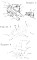
- This assembly is shown in greater details in the cross-section of Figure 4 , in which the same numeric references designate the same elements.
- a hatched part 23' illustrates the deformation of lip 23 due to the force fitting.
- lip 23 and rim 41 may be welded, e.g. by ultrasonic welding, in which case hating 23' would illustrate the welded portions.
- Cup-like body 4 has four spaced apart hooks 45 that are evenly distributed on rim 41 and that cooperate with corresponding passages 25 and hook retaining parts 26 at the periphery of cover body 2 to form a bayonet connection.
- the spacing between the point bearings is not affected by this locking. This spacing is entirely determined by the geometry (and position) of reference surface 42 so that tight tolerances for the bearings can be provided even though they are formed by moulding and not by additional diamonds.
- Each of the moulded bodies 2,4 has a through-opening communicating with measuring chamber 10 for circulating liquid through such flowmeter.
- a tubular inlet 47 is provided in cup-like body 4 and a tubular outlet 27 is provided in cover body 2.
- the inlet and the outlet could of course be switched. Moreover, the inlet and the outlet could be located on the same moulded body.
- cover body 2 has a socket 28 with a cavity 29 for receiving a sensor plug 5 as shown in Fig. 2 , the plug itself being illustrated in greater details in Fig. 3 in which the same numeric references designate the same elements.
- Sensor plug 5 has a housing 51 which may be closed with a lid or otherwise sealed (not shown). Housing 51 has a pair of front hooks 52 for securing plug 5 in cavity 29 and delimits an inner chamber 53.
- Chamber 53 contains a Hall sensor on a PCB 54 with cables 55 for connection to a control unit (not shown), for instance of a beverage preparation machine such as a coffee machine.
- a triple barrier is provided: the walls of socket 28 in cover body 2, housing 51 of plug 5 and a Kapton or other polyimide foil around PCB 54, whereby PCB 54 with the Hall sensor is safely sealed.
- the Hall sensor, PCB 54, housing 51 and cavity 29 are so arranged and positioned that when plug 5 is secured in socket 28, the Hall sensor is situated above extremity 32" with magnets 36.
- PCB 54 may be formed as part of a main board of the control unit to which cables 55 are connected. Hence, PCB 54 may be manufactured together with the control unit and then separated therefrom, e.g. cut away or broken off along a weakened line, before or after assembly of plug 5 before or after connection of cables 55, and then secured with plug 5 into socket 28. Hence, the manufacturing of the sensor device and its control unit can be simplified and optimised.
- the flowmeter may even be mounted directly onto the main board so that PCB 54 is an integral part of the main board and remains an integral part of the main board of the control unit, for instance as illustrated in greater details in WO 2009/043865 and in PCT/EP09/053368 .
- liquid is circulated from inlet 47 to outlet 27 via chamber 10.
- the flow of liquid will be intercepted by blades 31 thus driving shaft 32 in rotation about axis 3' between the point bearings at extremities 32', 32" of shaft 32.
- the speed of rotation of shaft 32 will be proportional to the flow of liquid in chamber 10 and driving measuring body 3.
- magnets 36 are rotated adjacent to the Hall sensor on PCB 54 that will detect the rotating magnetic field generated by the magnets and convert it into a corresponding electric signal having a frequency corresponding to the speed of rotation of shaft 32.
- the information regarding the flow of liquid will then be communicated to a control unit via cables 55.
Landscapes
- Physics & Mathematics (AREA)
- Fluid Mechanics (AREA)
- General Physics & Mathematics (AREA)
- Measuring Volume Flow (AREA)
- Apparatus For Making Beverages (AREA)
Claims (14)
- Débitmètre (1) pour une machine de préparation de boisson, comprenant:- un logement moulé (2, 4) délimitant une chambre de mesure (10) ;- un corps de mesure rotatif (3) avec un arbre rotatif (32) s'étendant à travers la chambre de mesure ; et- des paliers ponctuels (11, 37) pour le montage et le positionnement d'extrémités opposées (32', 32") de l'arbre rotatif dans le logement,chaque palier ponctuel étant formé d'une partie saillante (11) et d'une partie complémentaire renfoncée coopérante faisant face (37), associées respectivement au logement et à une extrémité de l'arbre rotatif, ou inversement,
caractérisé en ce que ladite partie saillante et ladite partie complémentaire renfoncée sont formées en une seule pièce avec le logement moulé et l'arbre rotatif. - Débitmètre selon la revendication 1, dans lequel la partie saillante (11) et la partie complémentaire (37) de chaque palier ponctuel sont respectivement composées de polyoxyméthylène (POM), tel que Schulaform 9A, et de polybutylène-téréphtalate (PBT), tel que Tecdur GK30, ou inversement.
- Débitmètre selon la revendication 1 ou 2, dans lequel le logement (2, 4) et/ou l'arbre (3) sont constitués d'un matériau composite contenant un matériau liant et une charge de stabilisation telle que des billes, en particulier des billes en verre, le matériau composite comprenant typiquement de 10 à 70 % en volume de matériau de charge, en particulier de 15 à 50 % en volume, tel que de 20 à 40 % en volume.
- Débitmètre selon l'une quelconque des revendications précédentes, dans lequel le logement est constitué de deux corps moulés assemblés (2, 4).
- Débitmètre selon la revendication 4, dans lequel le logement a un corps en forme de tasse (4) et un corps de couvercle (2).
- Débitmètre selon la revendication 5, dans lequel l'arbre rotatif (32) a un axe de rotation (3') qui s'étend entre un palier ponctuel situé sur le corps de couvercle (2) et un palier ponctuel faisant face (11) situé dans le corps en forme de tasse (4).
- Débitmètre selon la revendication 6, dans lequel le corps en forme de tasse (4) a un rebord (41) formant une surface de référence (42) perpendiculaire à l'axe de rotation (3') de l'arbre, le corps de couvercle (2) ayant une face interne (22) qui est pressée contre la surface de référence pour définir précisément un espace entre lesdits paliers ponctuels de façon à maintenir et à permettre une rotation libre de l'arbre (32) entre eux.
- Débitmètre selon les revendications 5, 6 ou 7, dans lequel le corps en forme de tasse (4) a un rebord (41) et dans lequel le corps de couvercle (2) a une lèvre d'étanchéité (23) la lèvre d'étanchéité étant sertie dans le rebord, ou inversement, pour sceller le corps de couvercle sur le corps en forme de tasse.
- Débitmètre selon l'une quelconque des revendications 5 à 8, dans lequel les corps (2, 4) sont assemblés par un dispositif de pression, loquet, collier de serrage ou crochet (25, 26, 45).
- Débitmètre selon la revendication 9, dans lequel les corps (2, 4) sont assemblés par une liaison à baïonnette.
- Débitmètre selon l'une quelconque des revendications 5 à 9, dans lequel chacun desdits corps moulés (2, 4) a une ouverture traversante (27, 47) communiquant avec la chambre de mesure (10) pour faire circuler un liquide à travers un tel débitmètre (1).
- Débitmètre selon l'une quelconque des revendications précédentes, dans lequel le logement (2, 4), comprend des parties saillantes faisant face (11) s'étendant dans la chambre (10) pour former les paliers ponctuels.
- Débitmètre selon l'une quelconque des revendications précédentes, dans lequel le logement (2, 4) comprend un dispositif de raccordement (28) pour y raccorder de manière libérable un dispositif de capteur (5).
- Machine de préparation de boisson ayant un circuit de circulation de liquide comprenant un débitmètre (1) tel que défini dans l'une quelconque des revendications précédentes.
Priority Applications (1)
| Application Number | Priority Date | Filing Date | Title |
|---|---|---|---|
| EP10725748.7A EP2446232B1 (fr) | 2009-06-25 | 2010-06-21 | Structure de débitmètre pour distributeur de boissons |
Applications Claiming Priority (3)
| Application Number | Priority Date | Filing Date | Title |
|---|---|---|---|
| EP09163815 | 2009-06-25 | ||
| EP10725748.7A EP2446232B1 (fr) | 2009-06-25 | 2010-06-21 | Structure de débitmètre pour distributeur de boissons |
| PCT/EP2010/058691 WO2010149602A1 (fr) | 2009-06-25 | 2010-06-21 | Structure de débitmètre pour distributeur de boisson |
Publications (2)
| Publication Number | Publication Date |
|---|---|
| EP2446232A1 EP2446232A1 (fr) | 2012-05-02 |
| EP2446232B1 true EP2446232B1 (fr) | 2017-08-23 |
Family
ID=41600423
Family Applications (1)
| Application Number | Title | Priority Date | Filing Date |
|---|---|---|---|
| EP10725748.7A Active EP2446232B1 (fr) | 2009-06-25 | 2010-06-21 | Structure de débitmètre pour distributeur de boissons |
Country Status (6)
| Country | Link |
|---|---|
| US (1) | US8789429B2 (fr) |
| EP (1) | EP2446232B1 (fr) |
| JP (1) | JP2012530920A (fr) |
| CN (1) | CN102460086A (fr) |
| CA (1) | CA2764127C (fr) |
| WO (1) | WO2010149602A1 (fr) |
Families Citing this family (12)
| Publication number | Priority date | Publication date | Assignee | Title |
|---|---|---|---|---|
| US8789429B2 (en) | 2009-06-25 | 2014-07-29 | Nestec S.A. | Flowmeter structure for a beverage machine |
| JP5525604B2 (ja) * | 2009-06-25 | 2014-06-18 | ネステク ソシエテ アノニム | 飲料調製装置用の流量計の材料 |
| DE202013100271U1 (de) * | 2013-01-21 | 2014-04-24 | Nestec S.A. | Durchflussmesseinrichtung für eine Getränkezubereitungsmaschine |
| WO2015048652A1 (fr) | 2013-09-30 | 2015-04-02 | Lincoln Industrial Corporation | Dispositif de mesure d'écoulement pour systèmes de lubrification |
| US20150245731A1 (en) * | 2014-02-28 | 2015-09-03 | Jeff Wu | Heating circulator cooker with openable pump housing |
| JP2019517833A (ja) | 2016-04-12 | 2019-06-27 | ネステク ソシエテ アノニム | 飲料ディスペンサ用のギヤポンプを備える液体圧送デバイス |
| NL2017477B1 (en) * | 2016-09-16 | 2018-03-22 | Leonardus Josephus Petrus Peters Marcel | Detectie-eenheid voor het detecteren van een ronddraaiende meetkogel, alsmede stromingsmeter voorzien van de detectie-eenheid |
| DE102017008401A1 (de) * | 2017-09-07 | 2019-03-07 | Stiebel Eltron Gmbh & Co. Kg | Durchflussmessvorrichtung für ein wasserführendes Haustechnikgerät und Haustechnikgerät |
| JP2019117174A (ja) * | 2017-12-27 | 2019-07-18 | 株式会社A&M | 羽根車式流量センサ及び流量制御システム |
| WO2020064982A1 (fr) | 2018-09-27 | 2020-04-02 | Société des Produits Nestlé SA | Unité de service adaptative d'une machine à boisson |
| EP3628195A1 (fr) | 2018-09-27 | 2020-04-01 | Société des Produits Nestlé S.A. | Machine de préparation de boissons avec détection de récipient |
| IT202000017830A1 (it) | 2020-07-23 | 2022-01-23 | Giorgio Antonio De | Sistema per la misurazione del flusso di un liquido |
Family Cites Families (47)
| Publication number | Priority date | Publication date | Assignee | Title |
|---|---|---|---|---|
| US4101874A (en) | 1976-07-29 | 1978-07-18 | The Perkin-Elmer Corporation | Fluid flow indicator and flow switch |
| DE7738382U1 (de) * | 1977-12-16 | 1978-04-13 | G. Kromschroeder Ag, 4500 Osnabrueck | Einstueckiger gaszaehlerbauteil |
| JPS54177960U (fr) | 1978-06-02 | 1979-12-15 | ||
| US4430901A (en) | 1980-07-24 | 1984-02-14 | Brown Boveri Kent Limited | Fluid meter |
| US4393724A (en) | 1981-06-12 | 1983-07-19 | Vdo Adolf Schindling Ag | Flow meter having a rotary body |
| JPS60106122A (ja) | 1983-11-15 | 1985-06-11 | マルコン電子株式会社 | 電解コンデンサ |
| DE8408445U1 (de) * | 1984-03-20 | 1985-01-03 | Plüss, Heinz, Schöndühl | Messgeraet fuer getraenkeleitungen |
| JPS61219835A (ja) | 1985-03-20 | 1986-09-30 | デイグメ−ザ アクチエンゲゼルシヤフト デイギタ−レ メステヒニク | 飲料配管用の測定計器 |
| JPS63167220U (fr) * | 1987-04-21 | 1988-10-31 | ||
| DE3854815D1 (de) | 1988-09-30 | 1996-02-01 | Siemens Ag | Verfahren zur Bestimmung und Verarbeitung von Korrekturwerten für selbstkalibrierende A/D- und D/A-Wandler und Rechenwerk zur Durchführung des Verfahrens |
| US5473932A (en) | 1991-11-07 | 1995-12-12 | M & Fc Holding Company, Inc. | Tandem rotor turbine meter and field calibration module |
| US5433118A (en) | 1993-12-10 | 1995-07-18 | Contadores De Agua De Zaragoza | Magnetic turbine rotor for low flow fluid meter |
| JPH07167689A (ja) | 1993-12-14 | 1995-07-04 | Omron Corp | 流量センサ |
| FR2721381B1 (fr) | 1994-06-20 | 1996-08-02 | Seb Sa | Dispositif de production d'eau chaude ou de vapeur. |
| DK0718602T3 (da) | 1994-12-20 | 2002-11-25 | Schlumberger Ind S R L | Enkeltstråle-væskemåler med forbedret følsomhed og reguleringseffekt |
| US5679906A (en) | 1995-03-15 | 1997-10-21 | Micro Motion, Inc. | Coriolis effect mass flowmeter using a single rotor having a flexible sensing element |
| DE29614076U1 (de) | 1996-08-15 | 1997-09-11 | Digmesa AG, Biel | Durchflußmeßgerät |
| US5866824A (en) | 1997-01-24 | 1999-02-02 | American Meter Company | Gas turbine meter |
| AU6703798A (en) * | 1997-03-19 | 1998-10-12 | Autotrol Corporation | Elbow mounted turbine flowmeter |
| US5876610A (en) * | 1997-03-19 | 1999-03-02 | Clack Corporation | Method and apparatus for monitoring liquid flow through an enclosed stream |
| US6019003A (en) * | 1997-08-12 | 2000-02-01 | Cito Products, Inc. | Flow sensor turbine assembly with sapphire bearing and metallic insert |
| US6065352A (en) | 1999-06-18 | 2000-05-23 | American Meter Company | Turbine meter with a rotor having accuracy enhancing rotor blades |
| JP2001077920A (ja) | 1999-09-07 | 2001-03-23 | Fujitsu Ltd | 交換機システム |
| JP2001276816A (ja) | 2000-03-30 | 2001-10-09 | Mitsubishi Rayon Co Ltd | 浄水器 |
| JP2002005701A (ja) | 2000-06-20 | 2002-01-09 | Shintoshi Service Center:Kk | 量水検針システム |
| JP2003042819A (ja) | 2001-08-02 | 2003-02-13 | Oval Corp | 渦流量計 |
| JP2005003552A (ja) | 2003-06-12 | 2005-01-06 | Univ Nihon | 回転羽根装置 |
| WO2004111579A1 (fr) * | 2003-06-12 | 2004-12-23 | Nihon University | Debitmetre |
| JP2005105059A (ja) | 2003-09-29 | 2005-04-21 | Mikuni Plast Kk | 地中又は地面敷設用成形品 |
| US7093503B1 (en) * | 2004-11-16 | 2006-08-22 | Energent Corporation | Variable phase turbine |
| DE102005042579B4 (de) | 2005-09-08 | 2007-07-12 | M & Fc Holding Llc | Turbinenzähler |
| EP2005153B1 (fr) * | 2006-04-07 | 2014-11-26 | Actaris Metering Systems | Ensemble d'entraînement magnétique pour compteur de flux de pétrole et de gaz propane liquide |
| DE102006036948A1 (de) * | 2006-08-06 | 2008-02-07 | Akdis, Mustafa, Dipl.-Ing. | Blutpumpe |
| GB2440964B (en) | 2006-08-18 | 2011-08-10 | Abb Ltd | Flow meter |
| JP2008096394A (ja) | 2006-10-16 | 2008-04-24 | Ricoh Elemex Corp | 流量計 |
| JP2008164544A (ja) | 2006-12-29 | 2008-07-17 | Takahata Seiko Kk | 水道メータ |
| JP2008209260A (ja) | 2007-02-27 | 2008-09-11 | Techno Excel Co Ltd | 異物対応型羽根車式流量センサ |
| JP5168944B2 (ja) | 2007-02-28 | 2013-03-27 | 三浦工業株式会社 | 羽根車式流量計 |
| DE202007003419U1 (de) * | 2007-03-07 | 2007-04-26 | Imk Automotive Gmbh | Planetengetriebe |
| DE202008018298U1 (de) * | 2007-07-19 | 2012-09-11 | Gealan Formteile Gmbh | Strömungserfassungsgerät |
| CL2008002963A1 (es) | 2007-10-04 | 2010-01-22 | Nestec Sa | Dispositivo calentador para una maquina para la preparacion de alimento liquido o bebida, que comprende una unidad termica con una masa metalica, a traves de la cual circula el liquido, y acumula calor y lo suministra al liquido, y tiene uno o mas componentes electricos asegurados en forma rigida a la unidad termica; y maquina. |
| EP2070454B1 (fr) | 2007-12-12 | 2015-07-15 | Nestec S.A. | Fabrication modulaire de machines de production de boissons |
| CN102014710B (zh) | 2008-04-22 | 2013-11-13 | 雀巢产品技术援助有限公司 | 饮料制备机的模块化组件 |
| US8006569B2 (en) | 2009-06-12 | 2011-08-30 | Sensus Usa Inc. | Magnetic flow meter |
| JP5525604B2 (ja) * | 2009-06-25 | 2014-06-18 | ネステク ソシエテ アノニム | 飲料調製装置用の流量計の材料 |
| US8789429B2 (en) | 2009-06-25 | 2014-07-29 | Nestec S.A. | Flowmeter structure for a beverage machine |
| US8397586B2 (en) | 2010-03-22 | 2013-03-19 | Honeywell International Inc. | Flow sensor assembly with porous insert |
-
2010
- 2010-06-21 US US13/378,608 patent/US8789429B2/en active Active
- 2010-06-21 WO PCT/EP2010/058691 patent/WO2010149602A1/fr active Application Filing
- 2010-06-21 JP JP2012516679A patent/JP2012530920A/ja active Pending
- 2010-06-21 CN CN2010800280943A patent/CN102460086A/zh active Pending
- 2010-06-21 EP EP10725748.7A patent/EP2446232B1/fr active Active
- 2010-06-21 CA CA2764127A patent/CA2764127C/fr active Active
Non-Patent Citations (1)
| Title |
|---|
| None * |
Also Published As
| Publication number | Publication date |
|---|---|
| US8789429B2 (en) | 2014-07-29 |
| JP2012530920A (ja) | 2012-12-06 |
| CA2764127C (fr) | 2017-08-22 |
| CA2764127A1 (fr) | 2010-12-29 |
| CN102460086A (zh) | 2012-05-16 |
| WO2010149602A1 (fr) | 2010-12-29 |
| US20120090472A1 (en) | 2012-04-19 |
| EP2446232A1 (fr) | 2012-05-02 |
Similar Documents
| Publication | Publication Date | Title |
|---|---|---|
| EP2446232B1 (fr) | Structure de débitmètre pour distributeur de boissons | |
| EP2446231B1 (fr) | Matériaux de débitmètre pour distributeur de boissons | |
| EP2507594B1 (fr) | Distributeur de boissons | |
| EP2507597B1 (fr) | Ensemble de débitmètre pour distributeur de boissons | |
| JP2012530920A5 (fr) | ||
| EP3442383B1 (fr) | Dispositif de pompage de liquide comprenant une pompe à engrenages pour distributeur de boissons |
Legal Events
| Date | Code | Title | Description |
|---|---|---|---|
| PUAI | Public reference made under article 153(3) epc to a published international application that has entered the european phase |
Free format text: ORIGINAL CODE: 0009012 |
|
| 17P | Request for examination filed |
Effective date: 20120125 |
|
| AK | Designated contracting states |
Kind code of ref document: A1 Designated state(s): AL AT BE BG CH CY CZ DE DK EE ES FI FR GB GR HR HU IE IS IT LI LT LU LV MC MK MT NL NO PL PT RO SE SI SK SM TR |
|
| DAX | Request for extension of the european patent (deleted) | ||
| REG | Reference to a national code |
Ref country code: HK Ref legal event code: DE Ref document number: 1170300 Country of ref document: HK |
|
| GRAP | Despatch of communication of intention to grant a patent |
Free format text: ORIGINAL CODE: EPIDOSNIGR1 |
|
| STAA | Information on the status of an ep patent application or granted ep patent |
Free format text: STATUS: GRANT OF PATENT IS INTENDED |
|
| INTG | Intention to grant announced |
Effective date: 20170515 |
|
| RIN1 | Information on inventor provided before grant (corrected) |
Inventor name: ETTER, STEFAN Inventor name: ZIEGLER, MARTIN |
|
| GRAS | Grant fee paid |
Free format text: ORIGINAL CODE: EPIDOSNIGR3 |
|
| GRAA | (expected) grant |
Free format text: ORIGINAL CODE: 0009210 |
|
| STAA | Information on the status of an ep patent application or granted ep patent |
Free format text: STATUS: THE PATENT HAS BEEN GRANTED |
|
| AK | Designated contracting states |
Kind code of ref document: B1 Designated state(s): AL AT BE BG CH CY CZ DE DK EE ES FI FR GB GR HR HU IE IS IT LI LT LU LV MC MK MT NL NO PL PT RO SE SI SK SM TR |
|
| REG | Reference to a national code |
Ref country code: GB Ref legal event code: FG4D |
|
| REG | Reference to a national code |
Ref country code: CH Ref legal event code: EP |
|
| REG | Reference to a national code |
Ref country code: AT Ref legal event code: REF Ref document number: 921839 Country of ref document: AT Kind code of ref document: T Effective date: 20170915 |
|
| REG | Reference to a national code |
Ref country code: IE Ref legal event code: FG4D |
|
| REG | Reference to a national code |
Ref country code: DE Ref legal event code: R096 Ref document number: 602010044612 Country of ref document: DE |
|
| REG | Reference to a national code |
Ref country code: NL Ref legal event code: FP |
|
| REG | Reference to a national code |
Ref country code: LT Ref legal event code: MG4D |
|
| REG | Reference to a national code |
Ref country code: AT Ref legal event code: MK05 Ref document number: 921839 Country of ref document: AT Kind code of ref document: T Effective date: 20170823 |
|
| PG25 | Lapsed in a contracting state [announced via postgrant information from national office to epo] |
Ref country code: NO Free format text: LAPSE BECAUSE OF FAILURE TO SUBMIT A TRANSLATION OF THE DESCRIPTION OR TO PAY THE FEE WITHIN THE PRESCRIBED TIME-LIMIT Effective date: 20171123 Ref country code: SE Free format text: LAPSE BECAUSE OF FAILURE TO SUBMIT A TRANSLATION OF THE DESCRIPTION OR TO PAY THE FEE WITHIN THE PRESCRIBED TIME-LIMIT Effective date: 20170823 Ref country code: FI Free format text: LAPSE BECAUSE OF FAILURE TO SUBMIT A TRANSLATION OF THE DESCRIPTION OR TO PAY THE FEE WITHIN THE PRESCRIBED TIME-LIMIT Effective date: 20170823 Ref country code: LT Free format text: LAPSE BECAUSE OF FAILURE TO SUBMIT A TRANSLATION OF THE DESCRIPTION OR TO PAY THE FEE WITHIN THE PRESCRIBED TIME-LIMIT Effective date: 20170823 Ref country code: HR Free format text: LAPSE BECAUSE OF FAILURE TO SUBMIT A TRANSLATION OF THE DESCRIPTION OR TO PAY THE FEE WITHIN THE PRESCRIBED TIME-LIMIT Effective date: 20170823 Ref country code: AT Free format text: LAPSE BECAUSE OF FAILURE TO SUBMIT A TRANSLATION OF THE DESCRIPTION OR TO PAY THE FEE WITHIN THE PRESCRIBED TIME-LIMIT Effective date: 20170823 |
|
| PG25 | Lapsed in a contracting state [announced via postgrant information from national office to epo] |
Ref country code: GR Free format text: LAPSE BECAUSE OF FAILURE TO SUBMIT A TRANSLATION OF THE DESCRIPTION OR TO PAY THE FEE WITHIN THE PRESCRIBED TIME-LIMIT Effective date: 20171124 Ref country code: LV Free format text: LAPSE BECAUSE OF FAILURE TO SUBMIT A TRANSLATION OF THE DESCRIPTION OR TO PAY THE FEE WITHIN THE PRESCRIBED TIME-LIMIT Effective date: 20170823 Ref country code: ES Free format text: LAPSE BECAUSE OF FAILURE TO SUBMIT A TRANSLATION OF THE DESCRIPTION OR TO PAY THE FEE WITHIN THE PRESCRIBED TIME-LIMIT Effective date: 20170823 Ref country code: IS Free format text: LAPSE BECAUSE OF FAILURE TO SUBMIT A TRANSLATION OF THE DESCRIPTION OR TO PAY THE FEE WITHIN THE PRESCRIBED TIME-LIMIT Effective date: 20171223 Ref country code: PL Free format text: LAPSE BECAUSE OF FAILURE TO SUBMIT A TRANSLATION OF THE DESCRIPTION OR TO PAY THE FEE WITHIN THE PRESCRIBED TIME-LIMIT Effective date: 20170823 Ref country code: BG Free format text: LAPSE BECAUSE OF FAILURE TO SUBMIT A TRANSLATION OF THE DESCRIPTION OR TO PAY THE FEE WITHIN THE PRESCRIBED TIME-LIMIT Effective date: 20171123 |
|
| PG25 | Lapsed in a contracting state [announced via postgrant information from national office to epo] |
Ref country code: CZ Free format text: LAPSE BECAUSE OF FAILURE TO SUBMIT A TRANSLATION OF THE DESCRIPTION OR TO PAY THE FEE WITHIN THE PRESCRIBED TIME-LIMIT Effective date: 20170823 Ref country code: DK Free format text: LAPSE BECAUSE OF FAILURE TO SUBMIT A TRANSLATION OF THE DESCRIPTION OR TO PAY THE FEE WITHIN THE PRESCRIBED TIME-LIMIT Effective date: 20170823 Ref country code: RO Free format text: LAPSE BECAUSE OF FAILURE TO SUBMIT A TRANSLATION OF THE DESCRIPTION OR TO PAY THE FEE WITHIN THE PRESCRIBED TIME-LIMIT Effective date: 20170823 |
|
| REG | Reference to a national code |
Ref country code: FR Ref legal event code: PLFP Year of fee payment: 9 |
|
| REG | Reference to a national code |
Ref country code: DE Ref legal event code: R097 Ref document number: 602010044612 Country of ref document: DE |
|
| PG25 | Lapsed in a contracting state [announced via postgrant information from national office to epo] |
Ref country code: EE Free format text: LAPSE BECAUSE OF FAILURE TO SUBMIT A TRANSLATION OF THE DESCRIPTION OR TO PAY THE FEE WITHIN THE PRESCRIBED TIME-LIMIT Effective date: 20170823 Ref country code: SK Free format text: LAPSE BECAUSE OF FAILURE TO SUBMIT A TRANSLATION OF THE DESCRIPTION OR TO PAY THE FEE WITHIN THE PRESCRIBED TIME-LIMIT Effective date: 20170823 Ref country code: SM Free format text: LAPSE BECAUSE OF FAILURE TO SUBMIT A TRANSLATION OF THE DESCRIPTION OR TO PAY THE FEE WITHIN THE PRESCRIBED TIME-LIMIT Effective date: 20170823 |
|
| PLBE | No opposition filed within time limit |
Free format text: ORIGINAL CODE: 0009261 |
|
| STAA | Information on the status of an ep patent application or granted ep patent |
Free format text: STATUS: NO OPPOSITION FILED WITHIN TIME LIMIT |
|
| 26N | No opposition filed |
Effective date: 20180524 |
|
| PG25 | Lapsed in a contracting state [announced via postgrant information from national office to epo] |
Ref country code: SI Free format text: LAPSE BECAUSE OF FAILURE TO SUBMIT A TRANSLATION OF THE DESCRIPTION OR TO PAY THE FEE WITHIN THE PRESCRIBED TIME-LIMIT Effective date: 20170823 |
|
| REG | Reference to a national code |
Ref country code: HK Ref legal event code: WD Ref document number: 1170300 Country of ref document: HK |
|
| GBPC | Gb: european patent ceased through non-payment of renewal fee |
Effective date: 20180621 |
|
| REG | Reference to a national code |
Ref country code: BE Ref legal event code: MM Effective date: 20180630 |
|
| REG | Reference to a national code |
Ref country code: IE Ref legal event code: MM4A |
|
| PG25 | Lapsed in a contracting state [announced via postgrant information from national office to epo] |
Ref country code: LU Free format text: LAPSE BECAUSE OF NON-PAYMENT OF DUE FEES Effective date: 20180621 Ref country code: MC Free format text: LAPSE BECAUSE OF FAILURE TO SUBMIT A TRANSLATION OF THE DESCRIPTION OR TO PAY THE FEE WITHIN THE PRESCRIBED TIME-LIMIT Effective date: 20170823 |
|
| PG25 | Lapsed in a contracting state [announced via postgrant information from national office to epo] |
Ref country code: IE Free format text: LAPSE BECAUSE OF NON-PAYMENT OF DUE FEES Effective date: 20180621 Ref country code: GB Free format text: LAPSE BECAUSE OF NON-PAYMENT OF DUE FEES Effective date: 20180621 |
|
| PG25 | Lapsed in a contracting state [announced via postgrant information from national office to epo] |
Ref country code: BE Free format text: LAPSE BECAUSE OF NON-PAYMENT OF DUE FEES Effective date: 20180630 |
|
| REG | Reference to a national code |
Ref country code: NL Ref legal event code: PD Owner name: SOCIETE DES PRODUITS NESTLE S.A.; CH Free format text: DETAILS ASSIGNMENT: CHANGE OF OWNER(S), MERGE Effective date: 20190620 |
|
| REG | Reference to a national code |
Ref country code: CH Ref legal event code: PFUS Owner name: SOCIETE DES PRODUITS NESTLE S.A., CH Free format text: FORMER OWNER: NESTEC S.A., CH |
|
| PG25 | Lapsed in a contracting state [announced via postgrant information from national office to epo] |
Ref country code: MT Free format text: LAPSE BECAUSE OF NON-PAYMENT OF DUE FEES Effective date: 20180621 |
|
| REG | Reference to a national code |
Ref country code: DE Ref legal event code: R082 Ref document number: 602010044612 Country of ref document: DE Representative=s name: MITSCHERLICH, PATENT- UND RECHTSANWAELTE PARTM, DE Ref country code: DE Ref legal event code: R081 Ref document number: 602010044612 Country of ref document: DE Owner name: SOCIETE DES PRODUITS NESTLE S.A., CH Free format text: FORMER OWNER: NESTEC S.A., VEVEY, CH |
|
| PG25 | Lapsed in a contracting state [announced via postgrant information from national office to epo] |
Ref country code: TR Free format text: LAPSE BECAUSE OF FAILURE TO SUBMIT A TRANSLATION OF THE DESCRIPTION OR TO PAY THE FEE WITHIN THE PRESCRIBED TIME-LIMIT Effective date: 20170823 |
|
| PG25 | Lapsed in a contracting state [announced via postgrant information from national office to epo] |
Ref country code: PT Free format text: LAPSE BECAUSE OF FAILURE TO SUBMIT A TRANSLATION OF THE DESCRIPTION OR TO PAY THE FEE WITHIN THE PRESCRIBED TIME-LIMIT Effective date: 20170823 Ref country code: HU Free format text: LAPSE BECAUSE OF FAILURE TO SUBMIT A TRANSLATION OF THE DESCRIPTION OR TO PAY THE FEE WITHIN THE PRESCRIBED TIME-LIMIT; INVALID AB INITIO Effective date: 20100621 |
|
| PG25 | Lapsed in a contracting state [announced via postgrant information from national office to epo] |
Ref country code: MK Free format text: LAPSE BECAUSE OF NON-PAYMENT OF DUE FEES Effective date: 20170823 Ref country code: CY Free format text: LAPSE BECAUSE OF FAILURE TO SUBMIT A TRANSLATION OF THE DESCRIPTION OR TO PAY THE FEE WITHIN THE PRESCRIBED TIME-LIMIT Effective date: 20170823 |
|
| PG25 | Lapsed in a contracting state [announced via postgrant information from national office to epo] |
Ref country code: AL Free format text: LAPSE BECAUSE OF FAILURE TO SUBMIT A TRANSLATION OF THE DESCRIPTION OR TO PAY THE FEE WITHIN THE PRESCRIBED TIME-LIMIT Effective date: 20170823 |
|
| P01 | Opt-out of the competence of the unified patent court (upc) registered |
Effective date: 20230527 |
|
| PGFP | Annual fee paid to national office [announced via postgrant information from national office to epo] |
Ref country code: CH Payment date: 20230702 Year of fee payment: 14 |
|
| PGFP | Annual fee paid to national office [announced via postgrant information from national office to epo] |
Ref country code: NL Payment date: 20240515 Year of fee payment: 15 |
|
| PGFP | Annual fee paid to national office [announced via postgrant information from national office to epo] |
Ref country code: DE Payment date: 20240502 Year of fee payment: 15 |
|
| PGFP | Annual fee paid to national office [announced via postgrant information from national office to epo] |
Ref country code: IT Payment date: 20240513 Year of fee payment: 15 Ref country code: FR Payment date: 20240509 Year of fee payment: 15 |