EP2441659A2 - Unterseeboot - Google Patents
Unterseeboot Download PDFInfo
- Publication number
- EP2441659A2 EP2441659A2 EP11184597A EP11184597A EP2441659A2 EP 2441659 A2 EP2441659 A2 EP 2441659A2 EP 11184597 A EP11184597 A EP 11184597A EP 11184597 A EP11184597 A EP 11184597A EP 2441659 A2 EP2441659 A2 EP 2441659A2
- Authority
- EP
- European Patent Office
- Prior art keywords
- lid
- gas
- container
- cover
- submarine
- Prior art date
- Legal status (The legal status is an assumption and is not a legal conclusion. Google has not performed a legal analysis and makes no representation as to the accuracy of the status listed.)
- Granted
Links
Images

Classifications
-
- B—PERFORMING OPERATIONS; TRANSPORTING
- B63—SHIPS OR OTHER WATERBORNE VESSELS; RELATED EQUIPMENT
- B63G—OFFENSIVE OR DEFENSIVE ARRANGEMENTS ON VESSELS; MINE-LAYING; MINE-SWEEPING; SUBMARINES; AIRCRAFT CARRIERS
- B63G8/00—Underwater vessels, e.g. submarines; Equipment specially adapted therefor
- B63G8/04—Superstructure
-
- B—PERFORMING OPERATIONS; TRANSPORTING
- B63—SHIPS OR OTHER WATERBORNE VESSELS; RELATED EQUIPMENT
- B63G—OFFENSIVE OR DEFENSIVE ARRANGEMENTS ON VESSELS; MINE-LAYING; MINE-SWEEPING; SUBMARINES; AIRCRAFT CARRIERS
- B63G8/00—Underwater vessels, e.g. submarines; Equipment specially adapted therefor
- B63G8/04—Superstructure
- B63G8/06—Conning-towers
-
- B—PERFORMING OPERATIONS; TRANSPORTING
- B63—SHIPS OR OTHER WATERBORNE VESSELS; RELATED EQUIPMENT
- B63B—SHIPS OR OTHER WATERBORNE VESSELS; EQUIPMENT FOR SHIPPING
- B63B19/00—Arrangements or adaptations of ports, doors, windows, port-holes, or other openings or covers
- B63B19/12—Hatches; Hatchways
- B63B19/14—Hatch covers
-
- B—PERFORMING OPERATIONS; TRANSPORTING
- B63—SHIPS OR OTHER WATERBORNE VESSELS; RELATED EQUIPMENT
- B63G—OFFENSIVE OR DEFENSIVE ARRANGEMENTS ON VESSELS; MINE-LAYING; MINE-SWEEPING; SUBMARINES; AIRCRAFT CARRIERS
- B63G8/00—Underwater vessels, e.g. submarines; Equipment specially adapted therefor
-
- B—PERFORMING OPERATIONS; TRANSPORTING
- B63—SHIPS OR OTHER WATERBORNE VESSELS; RELATED EQUIPMENT
- B63G—OFFENSIVE OR DEFENSIVE ARRANGEMENTS ON VESSELS; MINE-LAYING; MINE-SWEEPING; SUBMARINES; AIRCRAFT CARRIERS
- B63G8/00—Underwater vessels, e.g. submarines; Equipment specially adapted therefor
- B63G8/28—Arrangement of offensive or defensive equipment
- B63G8/30—Arrangement of offensive or defensive equipment of artillery or missile launching means
-
- B—PERFORMING OPERATIONS; TRANSPORTING
- B63—SHIPS OR OTHER WATERBORNE VESSELS; RELATED EQUIPMENT
- B63G—OFFENSIVE OR DEFENSIVE ARRANGEMENTS ON VESSELS; MINE-LAYING; MINE-SWEEPING; SUBMARINES; AIRCRAFT CARRIERS
- B63G8/00—Underwater vessels, e.g. submarines; Equipment specially adapted therefor
- B63G8/40—Rescue equipment for personnel
Definitions
- the invention relates to a submarine with a container which is lockable to one side, typically to an upper side and to the outside by a pressure-tight closing and pivotally hinged lid.
- Containers for the purposes of this invention for example, be arranged in the tower entrance and exit lock, but also those for dispensing weapons, decoys or other objects.
- These containers which are intended to carry persons or objects under water, are filled on land or from the pressure hull and, if they are not filled with liquid, are filled with air, d. H. filled with gas or a gas mixture. Before opening the lid under water, the container is flooded, d. H. in the container located gas or gas mixture is displaced by inflowing water and passed into a collection container.
- the lid which is typically arranged on the upper side, is convexly convex toward the outside due to the design, a gas bubble remains in the lid even after the flooding, which rises to the water surface when the lid is opened. These rising gas bubbles generate noise and are also visible on the surface, which is often not desired, especially in military operations, but also in other uses of a submarine.
- the invention is based on the object, a submarine, which has such a container with a pressure-tightly sealing to the outside lid, so that the Underwater container can be opened without gas bubbles rise.
- the submarine according to the invention with a container which is lockable to one side and to the outside by a pressure-tight and pivotally hinged lid is provided with means for flooding the sealed container under water and with means for collecting and storing the displaced during flooding from the container Gas or gas mixture equipped.
- it has a gas trap provided on the lid, which ensures that the gas or gas mixture present in the lid when the lid is closed after the container has flooded is collected and stored when the lid is opened so that no gas bubbles rise when the container is opened ,
- the basic idea of the present invention is that with containers of this type, the cover of which is typically arranged on the top and in which, after flooding the container under water due to its outwardly curved formation of gas collects, this capture by means of a so-called gas trap, ie this to collect and store under the lid collecting and virtually non-removable gas in the gas trap located in the lid so that it can not escape from this when you open the lid, but is guided back into the interior of the container during the subsequent closing.
- a so-called gas trap ie this to collect and store under the lid collecting and virtually non-removable gas in the gas trap located in the lid so that it can not escape from this when you open the lid, but is guided back into the interior of the container during the subsequent closing.
- This solution according to the invention not only has the advantage that when opening the lid under water after the flooding of the container no more gas bubbles rise, but also brings under water an effective in the opening direction of the lid buoyancy, which facilitates the opening of the lid and the 90th ° tilted open position of the lid supported and stabilized under water.
- the inventive solution is structurally simple and inexpensive, since such a case can be formed by a simple sheet metal construction on the inside of the lid or by molded parts, for example, glass fiber or carbon fiber reinforced plastic.
- the bag is provided according to a development of the invention, in the container a conduit for discharging the therein to provide located gas or gas mixture, the open end extends into the interior of the lid contour. A part of the gas which collects directly under the cover can already be removed via such a line, so that it is possible to ensure that the remaining quantity of residual gas in the pocket formed in the cover can be reliably collected and stored.
- the bag for collecting the residual gas 8 through the inside of the domed lid 3 on the one hand and the lid 3 (in the closed position) down substantially flat final wall 9 is formed, which has an opening 10 through which when closed Position of the lid 3, the upper end of the pipe 6 projects and surrounds this line end with distance.
- the collecting under the wall 9 during flooding and rising of the liquid gas is passed through the opening 10 in the wall formed by 9 and cover 3 bag.
- the Wall 9 is plate-shaped and consists of a closed lid in the normal operating position of the boat approximately horizontally extending circular wall part and an obliquely to the lid 3 extending flange wall part which is peripherally tight and firmly connected to the lid 3.
- the opening 10 is, as in Fig. 2 recognizable, arranged in the open position of the lid 3 below, so that the gas rising up through them can not escape.
- the pocket is formed by the inside of the lid 3 and the wall 9.
- a hollow body in the lid 3 and a hollow body can be incorporated flush and gap-free, which then forms the pocket as a gas trap, having an opening near the pivot point of the lid 3 and optionally from the lid 3 is removable.
Landscapes
- Engineering & Computer Science (AREA)
- Mechanical Engineering (AREA)
- Aviation & Aerospace Engineering (AREA)
- Chemical & Material Sciences (AREA)
- Combustion & Propulsion (AREA)
- Ocean & Marine Engineering (AREA)
- Closures For Containers (AREA)
- Underground Structures, Protecting, Testing And Restoring Foundations (AREA)
- Pressure Vessels And Lids Thereof (AREA)
Abstract
Description
- Die Erfindung betrifft ein Unterseeboot mit einem Behältnis, das zu einer Seite, typischerweise zu einer Oberseite und nach außen hin durch einen druckdicht verschließenden und schwenkbar angelenkten Deckel abschließbar ist. Behältnisse im Sinne dieser Erfindung können beispielsweise die im Turm angeordnete Ein- und Ausstiegsschleuse, aber auch solche zum Ausbringen von Waffen, Täuschkörpern oder anderen Gegenständen sein. Diese Behältnisse, die zum Ausbringen von Personen oder Gegenständen unter Wasser vorgesehen sind, werden an Land oder vom Druckkörper aus gefüllt und sind, sofern sie nicht flüssigkeitsgefüllt sind, mit Luft, d. h. mit Gas oder einem Gasgemisch gefüllt. Vor dem Öffnen des Deckels unter Wasser wird das Behältnis geflutet, d. h. im Behältnis befindliche Gas oder Gasgemisch wird durch einströmendes Wasser verdrängt und in einen Auffangbehälter geleitet. Da der typischerweise an der Oberseite angeordnete Deckel konstruktionsbedingt nach außen hin konvex gewölbt ausgebildet ist, verbleibt auch nach dem Fluten im Deckel eine Gasblase, die beim Öffnen des Deckels zur Wasseroberfläche aufsteigt. Diese aufsteigenden Gasblasen erzeugen Geräusche und sind auch an der Oberfläche sichtbar, was insbesondere bei militärischen Einsätzen, aber auch bei anderen Einsätzen eines Unterseebootes häufig nicht gewünscht wird.
- Vor diesem Hintergrund liegt der Erfindung die Aufgabe zugrunde, ein Unterseeboot, welches ein solches Behältnis mit einem nach außen druckdicht verschließenden Deckel aufweist, so auszubilden, dass das Behältnis unter Wasser geöffnet werden kann, ohne dass Gasblasen aufsteigen.
- Diese Aufgabe wird gemäß der Erfindung durch ein Unterseeboot mit den in Anspruch 1 angegebenen Merkmalen gelöst. Vorteilhafte Ausgestaltungen der Erfindung ergeben sich aus den Unteransprüchen, der nachfolgenden Beschreibung und der Zeichnung.
- Das erfindungsgemäße Unterseeboot mit einem Behältnis, das zu einer Seite und nach außen hin durch einen druckdicht verschließenden und schwenkbar angelenkten Deckel abschließbar ist, ist mit Mitteln zum Fluten des verschlossenen Behältnisses unter Wasser und mit Mitteln zum Auffangen und Speichern des beim Fluten aus dem Behältnis verdrängten Gases oder Gasgemisches ausgestattet. Gemäß der Erfindung weist es eine am Deckel vorgesehen Gasfalle auf, welche dafür sorgt, dass das in dem Deckel bei geschlossenem Deckel nach dem Fluten des Behältnisses befindliche Gas oder Gasgemisch beim Öffnen des Deckels aufgefangen und gespeichert wird, sodass keine Gasblasen beim Öffnen des Behältnisses aufsteigen.
- Grundgedanke der vorliegenden Erfindung ist es, dass bei Behältnissen dieser Art, deren Deckel typischerweise an der Oberseite angeordnet ist und in dem sich nach Fluten des Behältnisses unter Wasser aufgrund seiner nach außen gewölbten Ausbildung Gas sammelt, dieses mittels einer so genannten Gasfalle einzufangen, d. h. dieses sich unter dem Deckel sammelnde und praktisch nicht entfernbare Gas in dieser im Deckel befindlichen Gasfalle aufzufangen und zu speichern, sodass es beim Öffnen des Deckels nicht aus dieser entweichen kann, sondern beim nachfolgenden Verschließen wieder mit in das Innere des Behältnisses geführt wird.
- Diese erfindungsgemäße Lösung hat nicht nur den Vorteil, dass beim Öffnen des Deckels unter Wasser nach dem Fluten des Behältnisses keine Gasblasen mehr aufsteigen, sondern bringt darüber hinaus unter Wasser eine in Öffnungsrichtung des Deckels wirksame Auftriebskraft, die das Öffnen des Deckels erleichtert und die um 90° geschwenkte Offenstellung des Deckels unter Wasser unterstützt und stabilisiert.
- Die erfindungsgemäße Lösung ist konstruktiv einfach und wenig aufwändig, da eine solche Falle durch eine einfache Blechkonstruktion an der Innenseite des Deckels oder auch durch Formteile, beispielsweise aus glasfaser- oder kohlenstofffaserverstärktem Kunststoff gebildet sein kann.
- Vorteilhaft ist gemäß der Erfindung die Gasfalle bei einem nach außen hin konvex gewölbten Deckel durch eine an der Innenseite des Deckels ausgebildete und nur zur Anlenkseite des Deckels hin offene Tasche gebildet. Dabei richtet sich Form und Umfang der Tasche im Wesentlichen nach der Deckelform, um zu gewährleisten, dass das Gas dort vollständig aufgefangen und beim Öffnen gespeichert werden kann. Dabei genügt regelmäßig eine vergleichsweise kleine Öffnung der Tasche, wenn diese im Übrigen geschlossen ausgebildet ist und das durch die Wölbung an der Innenseite gebildete Volumen des Deckels nahezu vollständige einschließt. Es versteht sich, dass die Öffnung in der Regel zur Anlenkseite des Deckels hin gerichtet sein wird, da derartige Deckel typischerweise so angeordnet sind, dass sie nach oben aufschwenken. Bei Sonderkonstruktionen, die beispielsweise seitlich aufschwenken, versteht es sich, dass die Öffnung so angeordnet sein muss, dass sie möglichst weit unten angeordnet ist.
- Vorteilhaft wird eine solche Tasche durch einen Teil des Deckels selbst sowie eine davon ausgehend, mit Abstand dazu verlaufenden Wandung gebildet. Die Tasche ist dann durch die Innenseite des Deckels und die Wandung gebildet, wobei der von der Anlenkseite abgewandte Teil des Deckels Teil der Tasche bildet. Eine solche Wandung kann kostengünstig und mit konstruktiv einfachen Mitteln im Deckel angebracht werden, sei es bei einem Metalldeckel durch Anschweißen eines entsprechenden Blechformteils oder bei einem Kunststoffdeckel durch Anlaminieren eines entsprechenden Kunststoffformteils. Dabei ist es besonders vorteilhaft, wenn die so gebildete Tasche bei geschlossener Stellung des Deckels eine im Wesentlichen horizontal verlaufende Wandung aufweist, die mit Abstand zur Deckelinnenseite angeordnet ist und den oberen Querschnitt des Behältnisses ausfüllt. Dabei kann diese Wandung zur Anlenkstelle hin leicht nach oben schräg gestellt angeordnet sein, damit die unter der Wandung befindliche Luft vollständig durch das in das Behältnis einströmende Wasser verdrängt wird und sichergestellt ist, dass sich das gesamte Restgas innerhalb der Gasfalle, insbesondere der Tasche, sammelt.
- Gemäß einer vorteilhaften Weiterbildung der Erfindung kann die Tasche auch durch ein Hohlformteil mit Öffnung gebildet sein, das im Deckel derart angeordnet wird, dass die Öffnung des Formteils zur Anlenkseite des Deckels gerichtet ist bzw. bei Deckelkonstruktionen, die nicht nach oben öffnen, nach unten hin. Eine solche Ausbildung hat den Vorteil, dass die Tasche ohne konstruktive Änderung des Deckels gebildet werden kann, d. h., dass auch vorhandene Deckel mit einer solchen Gasfalle nachgerüstet werden können oder die Gasfalle bei Nichtbedarf gegebenenfalls auch entfernt werden kann. Ein solches Hohlformteil kann aus Kunststoff oder Blech gebildet sein und sollte vorteilhaft spaltfrei in den Deckel eingegliedert sein, um sicherzustellen, dass sich zwischen Formteil und Deckel kein Gas fängt. Dies kann gegebenenfalls auch durch Anbringung einer entsprechenden Dichtung am Formteil gewährleistet werden oder durch bündiges Einkleben mit einem geeigneten Kunststoff.
- Um die sich in der Gasfalle sammelnde Gasmenge möglichst gering zu halten, insbesondere so gering zu halten, dass sie durch die Falle, insbesondere die Tasche sicher aufgenommen werden kann, ist gemäß einer Weiterbildung der Erfindung vorgesehen, in dem Behältnis eine Leitung zum Abführen des darin befindlichen Gases oder Gasgemisches vorzusehen, deren offenes Ende bis in das Innere der Deckelkontur hineinreicht. Über eine solche Leitung kann bereits ein Teil des sich unter dem Deckel unmittelbar sammelnden Gases abgeführt werden, sodass sichergestellt werden kann, dass die verbleibende Restgasmenge in der im Deckel gebildeten Tasche zuverlässig aufgefangen und gespeichert werden kann.
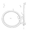
- Die Erfindung ist nachfolgend anhand eines in den Zeichnungen dargestellten Ausführungsbeispiels näher erläutert. Es zeigen:
- Fig. 1
- in stark vereinfachter schematischer Darstellung den Deckel einer Schleuse eines Unterseeboots in geschlossener und geöffneter Stellung jeweils in Seitenansicht, und
- Fig. 2
- den geöffneten Deckel in einer gegenüber
Fig. 1 um etwa 90° gedrehten Ansicht. - Das in den Figuren nicht im Einzelnen dargestellte Unterseeboot weist eine Schleuse auf, die ein Behältnis bildet und die aus einem im normalen Betrieb vertikal angeordneten Schacht 2 mit einem in den Figuren nicht dargestellten, den Schacht 2 nach unten hin verschließenden inneren Deckel sowie einen diesen nach oben hin verschließenden äußeren Deckel 3 aufweist. Der Deckel 3 ist an der Außenhaut 4 des Unterseeboots schwenkbar angelenkt, die Schwenkachse 5 liegt in
Figur 1 senkrecht zur Papierebene. Die Deckel schließen den Schacht 2 druckdicht ab. - Zum Ausschleusen einer Person oder eines Gegenstandes ist der Schacht 2 zunächst gas-, insbesondere luftgefüllt, der Deckel 3 druckdicht verschlossen, so wie dies in
Fig. 1 in der unteren Position dargestellt ist. Zum Ausschleusen der in der Schleuse 1 befindlichen Person oder des darin befindlichen Gegenstandes wird diese bei druckdicht verschlossenen beiden Deckeln unter Wasser durch Herstellen einer entsprechenden Leitungsverbindung geflutet. Das im Schacht 2 befindliche Gas wird in einen im U-Boot befindlichen oder zum System gehörenden Gasspeicher geleitet. Hierzu ist unter anderem eine parallel zum Schacht 2 an der Schachtwandung verlaufende Rohrleitung 6 vorgesehen, deren oberes Ende im Deckel 3, d. h. innerhalb der Deckelkontur, d. h. dem vom Deckel eingeschlossenen Raum mündet. Das im Schacht aufsteigende Wasser verdrängt das Gas solange, bis der Wasserspiegel 7 das obere offene Ende der Rohrleitung 6 erreicht hat. In dem nach außen konvex gewölbten Deckel 3 verbleibt Restgas 8. Dieses Restgas 8 wird durch eine im Deckel 3 integrierte Luftfalle in Form einer zur Anlenkseite des Deckels hin offenen Tasche gebildet, die eine Art Behälter für das Restgas 8 bildet und dafür sorgt, dass beim anschließenden Öffnen des Deckels 3, so wie es inFig. 1 durch den senkrecht stehenden Deckel 3 dargestellt ist, Gas nicht nach oben an die Wasseroberfläche aufsteigt, sondern vielmehr innerhalb dieser Tasche verbleibt. - In dem dargestellten Ausführungsbeispiel ist die Tasche zum Auffangen des Restgases 8 durch die Innenseite des gewölbten Deckels 3 einerseits sowie eine den Deckel 3 (in geschlossener Stellung) nach unten im Wesentlichen plan abschließende Wandung 9 gebildet, die eine Öffnung 10 aufweist, durch welche bei geschlossener Stellung des Deckels 3 das obere Ende der Rohrleitung 6 ragt und die dieses Leitungsende mit Abstand umgibt. Das sich unter der Wandung 9 beim Fluten und Aufsteigen der Flüssigkeit sammelnde Gas wird über die Öffnung 10 in die durch Wandung 9 und Deckel 3 gebildete Tasche geleitet. Die Wandung 9 ist tellerförmig ausgebildet und besteht aus einem bei geschlossenem Deckel in normaler Betriebsstellung des Bootes etwa horizontal verlaufenden kreisrunden Wandungsteil sowie einem schräg zum Deckel 3 hin verlaufenden flanschartigen Wandungsteil, der umfangsseitig dicht und fest mit dem Deckel 3 verbunden ist. Die Öffnung 10 ist, wie in
Fig. 2 erkennbar, in geöffneter Stellung des Deckels 3 unten angeordnet, sodass das nach oben aufsteigende Gas durch diese nicht entweichen kann. - Im vorstehend beschriebenen Ausführungsbeispiel ist die Tasche durch die Innenseite des Deckels 3 und die Wandung 9 gebildet. Alternativ kann in den Deckel 3 auch ein Hohlkörper bündig und spaltfrei eingegliedert werden, der dann die Tasche als Gasfalle bildet, eine Öffnung nahe der Anlenkstelle des Deckels 3 aufweist und gegebenenfalls aus dem Deckel 3 entfernbar ist.
-
- 1 -
- Schleuse
- 2 -
- Schacht
- 3 -
- Deckel
- 4 -
- Außenhaut
- 5 -
- Schwenkachse
- 6 -
- Rohrleitung
- 7 -
- Wasserspiegel
- 8 -
- Restgas
- 9 -
- Wandung
- 10 -
- Öffnung
Claims (9)
- Unterseeboot mit einem Behältnis (2), das zu einer Seite und nach außen hin durch einen druckdicht verschließenden und schwenkbar angelenkten Deckel (3) abschließbar ist, mit Mitteln zum Fluten des verschlossenen Behältnisses (2) unter Wasser und mit Mitteln zum Auffangen und Speichern des beim Fluten aus dem Behältnis (2) verdrängten Gases oder Gasgemisches und mit einer am Deckel (3) vorgesehenen Gasfalle, welche das in dem Deckel (3) befindliche Gas oder Gasgemisch (8) beim Öffnen des Deckels (3) auffängt und speichert.
- Unterseeboot nach Anspruch 1, bei dem der Deckel (3) nach außen hin konvex gewölbt ausgebildet ist und die Gasfalle durch eine an der Innenseite des Deckels (3) ausgebildete und nur zur Anlenkseite des Deckels (3) hin offene Tasche gebildet ist.
- Unterseeboot nach Anspruch 1 oder 2, bei dem die Tasche durch einen von der Anlenkseite abgewandten Teil des Deckels (3) einerseits und einer davon ausgehenden mit Abstand dazu verlaufenden Wandung (9) andererseits gebildet ist.
- Unterseeboot nach Anspruch 2 oder 3, dadurch gekennzeichnet, dass die Tasche eine in geschlossener Stellung des Deckels (3) im Wesentlichen horizontal verlaufende Wandung (9) aufweist, die mit Abstand zur Deckelinnenseite angeordnet ist und den oberen Querschnitt des Behältnisses (2) ausfüllt.
- Unterseeboot nach Anspruch 2 oder 4, bei dem die Tasche durch ein im Deckel (3) angeordnetes Hohlformteil mit einer Öffnung gebildet ist, wobei die Öffnung des Hohlformteils nahe der Anlenkseite des Deckels (3) angeordnet ist.
- Unterseeboot nach Anspruch 4, bei dem das Hohlformteil spaltfrei in den Deckel (3) eingegliedert ist.
- Unterseeboot nach einem der vorhergehenden Ansprüche, bei dem in dem Behältnis (2) eine Leitung (6) zum Abführen des darin befindlichen Gases oder Gasgemisches (8) vorgesehen ist, deren offenes Ende bis ins Innere der Deckelkontur hinein reicht.
- Unterseeboot nach einem der vorhergehenden Ansprüche, bei dem der Deckel (3) den äußeren Verschluss einer in den Druckkörper führenden Schleuse bildet.
- Behältnis als Gasfalle zum Anbringen im Deckel (3) eines Unterseeboots, wobei das Behältnis geschlossen ausgebildet ist und eine Öffnung aufweist, die im montierten Zustand nahe der Anlenkseite des Deckels angeordnet ist.
Applications Claiming Priority (1)
| Application Number | Priority Date | Filing Date | Title |
|---|---|---|---|
| DE102010048628A DE102010048628B3 (de) | 2010-10-15 | 2010-10-15 | Unterseeboot |
Publications (3)
| Publication Number | Publication Date |
|---|---|
| EP2441659A2 true EP2441659A2 (de) | 2012-04-18 |
| EP2441659A3 EP2441659A3 (de) | 2015-08-05 |
| EP2441659B1 EP2441659B1 (de) | 2019-11-06 |
Family
ID=44759585
Family Applications (1)
| Application Number | Title | Priority Date | Filing Date |
|---|---|---|---|
| EP11184597.0A Active EP2441659B1 (de) | 2010-10-15 | 2011-10-11 | Unterseeboot |
Country Status (4)
| Country | Link |
|---|---|
| EP (1) | EP2441659B1 (de) |
| KR (1) | KR101508243B1 (de) |
| DE (1) | DE102010048628B3 (de) |
| ES (1) | ES2770650T3 (de) |
Families Citing this family (1)
| Publication number | Priority date | Publication date | Assignee | Title |
|---|---|---|---|---|
| FR3034745B1 (fr) * | 2015-04-07 | 2017-04-28 | Dcns | Panneau de coque avec trappe de grande dimension |
Family Cites Families (4)
| Publication number | Priority date | Publication date | Assignee | Title |
|---|---|---|---|---|
| FR2560146A1 (fr) * | 1984-02-24 | 1985-08-30 | Wieczorek Julien | Engins pour sous-marins |
| DE102004037951B4 (de) * | 2004-08-05 | 2006-05-04 | Howaldtswerke-Deutsche Werft Gmbh | Unterseeboot |
| KR20090108680A (ko) * | 2006-03-15 | 2009-10-16 | 호발츠벨케 도이췌 벨프트 게엠베하 | 선체와 외피 사이에 저장된 잠수함-구명 용구를 구비한 잠수함 |
| KR100841812B1 (ko) * | 2006-10-11 | 2008-06-26 | 대우조선해양 주식회사 | 잠수함용 통행구 |
-
2010
- 2010-10-15 DE DE102010048628A patent/DE102010048628B3/de active Active
-
2011
- 2011-10-10 KR KR20110103230A patent/KR101508243B1/ko active Active
- 2011-10-11 EP EP11184597.0A patent/EP2441659B1/de active Active
- 2011-10-11 ES ES11184597T patent/ES2770650T3/es active Active
Non-Patent Citations (1)
| Title |
|---|
| None |
Also Published As
| Publication number | Publication date |
|---|---|
| DE102010048628B3 (de) | 2012-03-01 |
| KR20140095598A (ko) | 2014-08-04 |
| KR101508243B1 (ko) | 2015-04-06 |
| EP2441659A3 (de) | 2015-08-05 |
| EP2441659B1 (de) | 2019-11-06 |
| ES2770650T3 (es) | 2020-07-02 |
Similar Documents
| Publication | Publication Date | Title |
|---|---|---|
| EP2441659B1 (de) | Unterseeboot | |
| WO2014072160A1 (de) | Aufsatz für einen flüssigkeitsbehälter | |
| DE19936161C1 (de) | Sicherheitsventil insbesondere für eine Betankungsentlüftungsleitung | |
| DE4322260C2 (de) | Klappe in einem Abwasserrohr | |
| EP2847056B1 (de) | Schienenfahrzeug mit einem innen liegenden tank | |
| DE102010048629B4 (de) | Unterseeboot | |
| DE3142674A1 (de) | "tankcontainer" | |
| DE202015000670U1 (de) | Saugrohr für Dosier- oder Sprühvorrichtung | |
| DE2658896C3 (de) | Altölauffang- und Sammelanlage | |
| DE444013C (de) | Gefaess zur Dickteerausscheidung aus teerhaltigen Ammoniakwaessern | |
| DE102019203075B4 (de) | Deckel mit Entlüftung | |
| DE602004000453T2 (de) | Kraftstoffsbehälter | |
| DE102010041216A1 (de) | Tank eines Dosiersystems zum Einbringen von Reduktionsmittel in das Abgas einer Verbrennungskraftmaschine | |
| DE102009047133A1 (de) | Vorrichtung für das automatisch kontrollierte Restentleeren von Flüssiggas-Drucktanks auf Wasserfahrzeugen | |
| AT502183B1 (de) | Betankungsvorrichtung | |
| DE715834C (de) | Betriebsstoffbehaelter in Fahrzeugen, insbesondere in Luftfahrzeugen | |
| DE3522199A1 (de) | Behaelter zur aufnahme von schadstoffe enthaltenden medien mit hilfe von unterdruck | |
| DE3424934A1 (de) | Fluessigkeitsdaempfer fuer einen kraftstoffbehaelter | |
| DE19807664A1 (de) | Schwimmerventil für ein Sauggerät | |
| DE3031945A1 (de) | Verschluss fuer einen kanister | |
| DE1089083B (de) | Wasser-Sicherheitsvorlage fuer Kernreaktoren | |
| EP0333127B1 (de) | Sammel- und Transporttank | |
| DE202014006596U1 (de) | Behältereinrichtung für Wasser | |
| DE7102473U (de) | Flüssigkeitsbehälter, insbesondere Heiz ölbehälter | |
| DE9204749U1 (de) | Selbstschließender Tankverschluß |
Legal Events
| Date | Code | Title | Description |
|---|---|---|---|
| PUAI | Public reference made under article 153(3) epc to a published international application that has entered the european phase |
Free format text: ORIGINAL CODE: 0009012 |
|
| AK | Designated contracting states |
Kind code of ref document: A2 Designated state(s): AL AT BE BG CH CY CZ DE DK EE ES FI FR GB GR HR HU IE IS IT LI LT LU LV MC MK MT NL NO PL PT RO RS SE SI SK SM TR |
|
| AX | Request for extension of the european patent |
Extension state: BA ME |
|
| RAP1 | Party data changed (applicant data changed or rights of an application transferred) |
Owner name: THYSSENKRUPP MARINE SYSTEMS GMBH |
|
| PUAL | Search report despatched |
Free format text: ORIGINAL CODE: 0009013 |
|
| AK | Designated contracting states |
Kind code of ref document: A3 Designated state(s): AL AT BE BG CH CY CZ DE DK EE ES FI FR GB GR HR HU IE IS IT LI LT LU LV MC MK MT NL NO PL PT RO RS SE SI SK SM TR |
|
| AX | Request for extension of the european patent |
Extension state: BA ME |
|
| RIC1 | Information provided on ipc code assigned before grant |
Ipc: B63B 19/14 20060101AFI20150629BHEP Ipc: B63G 8/00 20060101ALI20150629BHEP |
|
| 17P | Request for examination filed |
Effective date: 20160201 |
|
| RBV | Designated contracting states (corrected) |
Designated state(s): AL AT BE BG CH CY CZ DE DK EE ES FI FR GB GR HR HU IE IS IT LI LT LU LV MC MK MT NL NO PL PT RO RS SE SI SK SM TR |
|
| STAA | Information on the status of an ep patent application or granted ep patent |
Free format text: STATUS: EXAMINATION IS IN PROGRESS |
|
| 17Q | First examination report despatched |
Effective date: 20181105 |
|
| GRAP | Despatch of communication of intention to grant a patent |
Free format text: ORIGINAL CODE: EPIDOSNIGR1 |
|
| STAA | Information on the status of an ep patent application or granted ep patent |
Free format text: STATUS: GRANT OF PATENT IS INTENDED |
|
| INTG | Intention to grant announced |
Effective date: 20190624 |
|
| RBV | Designated contracting states (corrected) |
Designated state(s): AL AT BE BG CH CY CZ DK EE ES FI FR GB GR HR HU IE IS IT LI LT LU LV MC MK MT NL NO PL PT RO RS SE SI SK SM TR |
|
| REG | Reference to a national code |
Ref country code: DE Ref legal event code: R108 |
|
| GRAS | Grant fee paid |
Free format text: ORIGINAL CODE: EPIDOSNIGR3 |
|
| RAP1 | Party data changed (applicant data changed or rights of an application transferred) |
Owner name: THYSSENKRUPP MARINE SYSTEMS GMBH |
|
| GRAA | (expected) grant |
Free format text: ORIGINAL CODE: 0009210 |
|
| STAA | Information on the status of an ep patent application or granted ep patent |
Free format text: STATUS: THE PATENT HAS BEEN GRANTED |
|
| AK | Designated contracting states |
Kind code of ref document: B1 Designated state(s): AL AT BE BG CH CY CZ DK EE ES FI FR GB GR HR HU IE IS IT LI LT LU LV MC MK MT NL NO PL PT RO RS SE SI SK SM TR |
|
| REG | Reference to a national code |
Ref country code: GB Ref legal event code: FG4D Free format text: NOT ENGLISH |
|
| REG | Reference to a national code |
Ref country code: CH Ref legal event code: EP Ref country code: AT Ref legal event code: REF Ref document number: 1198398 Country of ref document: AT Kind code of ref document: T Effective date: 20191115 |
|
| REG | Reference to a national code |
Ref country code: IE Ref legal event code: FG4D Free format text: LANGUAGE OF EP DOCUMENT: GERMAN |
|
| REG | Reference to a national code |
Ref country code: NL Ref legal event code: MP Effective date: 20191106 |
|
| REG | Reference to a national code |
Ref country code: LT Ref legal event code: MG4D |
|
| PG25 | Lapsed in a contracting state [announced via postgrant information from national office to epo] |
Ref country code: PT Free format text: LAPSE BECAUSE OF FAILURE TO SUBMIT A TRANSLATION OF THE DESCRIPTION OR TO PAY THE FEE WITHIN THE PRESCRIBED TIME-LIMIT Effective date: 20200306 Ref country code: SE Free format text: LAPSE BECAUSE OF FAILURE TO SUBMIT A TRANSLATION OF THE DESCRIPTION OR TO PAY THE FEE WITHIN THE PRESCRIBED TIME-LIMIT Effective date: 20191106 Ref country code: LV Free format text: LAPSE BECAUSE OF FAILURE TO SUBMIT A TRANSLATION OF THE DESCRIPTION OR TO PAY THE FEE WITHIN THE PRESCRIBED TIME-LIMIT Effective date: 20191106 Ref country code: PL Free format text: LAPSE BECAUSE OF FAILURE TO SUBMIT A TRANSLATION OF THE DESCRIPTION OR TO PAY THE FEE WITHIN THE PRESCRIBED TIME-LIMIT Effective date: 20191106 Ref country code: GR Free format text: LAPSE BECAUSE OF FAILURE TO SUBMIT A TRANSLATION OF THE DESCRIPTION OR TO PAY THE FEE WITHIN THE PRESCRIBED TIME-LIMIT Effective date: 20200207 Ref country code: NO Free format text: LAPSE BECAUSE OF FAILURE TO SUBMIT A TRANSLATION OF THE DESCRIPTION OR TO PAY THE FEE WITHIN THE PRESCRIBED TIME-LIMIT Effective date: 20200206 Ref country code: BG Free format text: LAPSE BECAUSE OF FAILURE TO SUBMIT A TRANSLATION OF THE DESCRIPTION OR TO PAY THE FEE WITHIN THE PRESCRIBED TIME-LIMIT Effective date: 20200206 Ref country code: LT Free format text: LAPSE BECAUSE OF FAILURE TO SUBMIT A TRANSLATION OF THE DESCRIPTION OR TO PAY THE FEE WITHIN THE PRESCRIBED TIME-LIMIT Effective date: 20191106 Ref country code: FI Free format text: LAPSE BECAUSE OF FAILURE TO SUBMIT A TRANSLATION OF THE DESCRIPTION OR TO PAY THE FEE WITHIN THE PRESCRIBED TIME-LIMIT Effective date: 20191106 Ref country code: NL Free format text: LAPSE BECAUSE OF FAILURE TO SUBMIT A TRANSLATION OF THE DESCRIPTION OR TO PAY THE FEE WITHIN THE PRESCRIBED TIME-LIMIT Effective date: 20191106 |
|
| PG25 | Lapsed in a contracting state [announced via postgrant information from national office to epo] |
Ref country code: RS Free format text: LAPSE BECAUSE OF FAILURE TO SUBMIT A TRANSLATION OF THE DESCRIPTION OR TO PAY THE FEE WITHIN THE PRESCRIBED TIME-LIMIT Effective date: 20191106 Ref country code: HR Free format text: LAPSE BECAUSE OF FAILURE TO SUBMIT A TRANSLATION OF THE DESCRIPTION OR TO PAY THE FEE WITHIN THE PRESCRIBED TIME-LIMIT Effective date: 20191106 Ref country code: IS Free format text: LAPSE BECAUSE OF FAILURE TO SUBMIT A TRANSLATION OF THE DESCRIPTION OR TO PAY THE FEE WITHIN THE PRESCRIBED TIME-LIMIT Effective date: 20200306 |
|
| PG25 | Lapsed in a contracting state [announced via postgrant information from national office to epo] |
Ref country code: AL Free format text: LAPSE BECAUSE OF FAILURE TO SUBMIT A TRANSLATION OF THE DESCRIPTION OR TO PAY THE FEE WITHIN THE PRESCRIBED TIME-LIMIT Effective date: 20191106 |
|
| REG | Reference to a national code |
Ref country code: ES Ref legal event code: FG2A Ref document number: 2770650 Country of ref document: ES Kind code of ref document: T3 Effective date: 20200702 |
|
| PG25 | Lapsed in a contracting state [announced via postgrant information from national office to epo] |
Ref country code: EE Free format text: LAPSE BECAUSE OF FAILURE TO SUBMIT A TRANSLATION OF THE DESCRIPTION OR TO PAY THE FEE WITHIN THE PRESCRIBED TIME-LIMIT Effective date: 20191106 Ref country code: DK Free format text: LAPSE BECAUSE OF FAILURE TO SUBMIT A TRANSLATION OF THE DESCRIPTION OR TO PAY THE FEE WITHIN THE PRESCRIBED TIME-LIMIT Effective date: 20191106 Ref country code: CZ Free format text: LAPSE BECAUSE OF FAILURE TO SUBMIT A TRANSLATION OF THE DESCRIPTION OR TO PAY THE FEE WITHIN THE PRESCRIBED TIME-LIMIT Effective date: 20191106 Ref country code: RO Free format text: LAPSE BECAUSE OF FAILURE TO SUBMIT A TRANSLATION OF THE DESCRIPTION OR TO PAY THE FEE WITHIN THE PRESCRIBED TIME-LIMIT Effective date: 20191106 |
|
| PG25 | Lapsed in a contracting state [announced via postgrant information from national office to epo] |
Ref country code: SM Free format text: LAPSE BECAUSE OF FAILURE TO SUBMIT A TRANSLATION OF THE DESCRIPTION OR TO PAY THE FEE WITHIN THE PRESCRIBED TIME-LIMIT Effective date: 20191106 Ref country code: SK Free format text: LAPSE BECAUSE OF FAILURE TO SUBMIT A TRANSLATION OF THE DESCRIPTION OR TO PAY THE FEE WITHIN THE PRESCRIBED TIME-LIMIT Effective date: 20191106 |
|
| PLBE | No opposition filed within time limit |
Free format text: ORIGINAL CODE: 0009261 |
|
| STAA | Information on the status of an ep patent application or granted ep patent |
Free format text: STATUS: NO OPPOSITION FILED WITHIN TIME LIMIT |
|
| 26N | No opposition filed |
Effective date: 20200807 |
|
| PG25 | Lapsed in a contracting state [announced via postgrant information from national office to epo] |
Ref country code: SI Free format text: LAPSE BECAUSE OF FAILURE TO SUBMIT A TRANSLATION OF THE DESCRIPTION OR TO PAY THE FEE WITHIN THE PRESCRIBED TIME-LIMIT Effective date: 20191106 |
|
| REG | Reference to a national code |
Ref country code: CH Ref legal event code: PL |
|
| PG25 | Lapsed in a contracting state [announced via postgrant information from national office to epo] |
Ref country code: LU Free format text: LAPSE BECAUSE OF NON-PAYMENT OF DUE FEES Effective date: 20201011 Ref country code: MC Free format text: LAPSE BECAUSE OF FAILURE TO SUBMIT A TRANSLATION OF THE DESCRIPTION OR TO PAY THE FEE WITHIN THE PRESCRIBED TIME-LIMIT Effective date: 20191106 |
|
| REG | Reference to a national code |
Ref country code: BE Ref legal event code: MM Effective date: 20201031 |
|
| PG25 | Lapsed in a contracting state [announced via postgrant information from national office to epo] |
Ref country code: CH Free format text: LAPSE BECAUSE OF NON-PAYMENT OF DUE FEES Effective date: 20201031 Ref country code: BE Free format text: LAPSE BECAUSE OF NON-PAYMENT OF DUE FEES Effective date: 20201031 Ref country code: LI Free format text: LAPSE BECAUSE OF NON-PAYMENT OF DUE FEES Effective date: 20201031 |
|
| PG25 | Lapsed in a contracting state [announced via postgrant information from national office to epo] |
Ref country code: IE Free format text: LAPSE BECAUSE OF NON-PAYMENT OF DUE FEES Effective date: 20201011 |
|
| REG | Reference to a national code |
Ref country code: AT Ref legal event code: MM01 Ref document number: 1198398 Country of ref document: AT Kind code of ref document: T Effective date: 20201011 |
|
| PG25 | Lapsed in a contracting state [announced via postgrant information from national office to epo] |
Ref country code: AT Free format text: LAPSE BECAUSE OF NON-PAYMENT OF DUE FEES Effective date: 20201011 |
|
| PG25 | Lapsed in a contracting state [announced via postgrant information from national office to epo] |
Ref country code: TR Free format text: LAPSE BECAUSE OF FAILURE TO SUBMIT A TRANSLATION OF THE DESCRIPTION OR TO PAY THE FEE WITHIN THE PRESCRIBED TIME-LIMIT Effective date: 20191106 Ref country code: MT Free format text: LAPSE BECAUSE OF FAILURE TO SUBMIT A TRANSLATION OF THE DESCRIPTION OR TO PAY THE FEE WITHIN THE PRESCRIBED TIME-LIMIT Effective date: 20191106 Ref country code: CY Free format text: LAPSE BECAUSE OF FAILURE TO SUBMIT A TRANSLATION OF THE DESCRIPTION OR TO PAY THE FEE WITHIN THE PRESCRIBED TIME-LIMIT Effective date: 20191106 |
|
| PG25 | Lapsed in a contracting state [announced via postgrant information from national office to epo] |
Ref country code: MK Free format text: LAPSE BECAUSE OF FAILURE TO SUBMIT A TRANSLATION OF THE DESCRIPTION OR TO PAY THE FEE WITHIN THE PRESCRIBED TIME-LIMIT Effective date: 20191106 |
|
| PGFP | Annual fee paid to national office [announced via postgrant information from national office to epo] |
Ref country code: GB Payment date: 20251022 Year of fee payment: 15 |
|
| PGFP | Annual fee paid to national office [announced via postgrant information from national office to epo] |
Ref country code: IT Payment date: 20251024 Year of fee payment: 15 |
|
| PGFP | Annual fee paid to national office [announced via postgrant information from national office to epo] |
Ref country code: FR Payment date: 20251030 Year of fee payment: 15 |
|
| PGFP | Annual fee paid to national office [announced via postgrant information from national office to epo] |
Ref country code: ES Payment date: 20251210 Year of fee payment: 15 |