EP2441618A2 - Klappbarer Flaschenhalter - Google Patents
Klappbarer Flaschenhalter Download PDFInfo
- Publication number
- EP2441618A2 EP2441618A2 EP11466029A EP11466029A EP2441618A2 EP 2441618 A2 EP2441618 A2 EP 2441618A2 EP 11466029 A EP11466029 A EP 11466029A EP 11466029 A EP11466029 A EP 11466029A EP 2441618 A2 EP2441618 A2 EP 2441618A2
- Authority
- EP
- European Patent Office
- Prior art keywords
- holder
- frame
- bottle
- shaped lid
- Prior art date
- Legal status (The legal status is an assumption and is not a legal conclusion. Google has not performed a legal analysis and makes no representation as to the accuracy of the status listed.)
- Withdrawn
Links
Images

Classifications
-
- B—PERFORMING OPERATIONS; TRANSPORTING
- B60—VEHICLES IN GENERAL
- B60N—SEATS SPECIALLY ADAPTED FOR VEHICLES; VEHICLE PASSENGER ACCOMMODATION NOT OTHERWISE PROVIDED FOR
- B60N3/00—Arrangements or adaptations of other passenger fittings, not otherwise provided for
- B60N3/10—Arrangements or adaptations of other passenger fittings, not otherwise provided for of receptacles for food or beverages, e.g. refrigerated
- B60N3/102—Arrangements or adaptations of other passenger fittings, not otherwise provided for of receptacles for food or beverages, e.g. refrigerated storable or foldable in a non-use position
-
- B—PERFORMING OPERATIONS; TRANSPORTING
- B60—VEHICLES IN GENERAL
- B60N—SEATS SPECIALLY ADAPTED FOR VEHICLES; VEHICLE PASSENGER ACCOMMODATION NOT OTHERWISE PROVIDED FOR
- B60N3/00—Arrangements or adaptations of other passenger fittings, not otherwise provided for
- B60N3/10—Arrangements or adaptations of other passenger fittings, not otherwise provided for of receptacles for food or beverages, e.g. refrigerated
- B60N3/105—Arrangements or adaptations of other passenger fittings, not otherwise provided for of receptacles for food or beverages, e.g. refrigerated for receptables of different size or shape
-
- B—PERFORMING OPERATIONS; TRANSPORTING
- B60—VEHICLES IN GENERAL
- B60N—SEATS SPECIALLY ADAPTED FOR VEHICLES; VEHICLE PASSENGER ACCOMMODATION NOT OTHERWISE PROVIDED FOR
- B60N2/00—Seats specially adapted for vehicles; Arrangement or mounting of seats in vehicles
- B60N2/02—Seats specially adapted for vehicles; Arrangement or mounting of seats in vehicles the seat or part thereof being movable, e.g. adjustable
- B60N2002/0204—Seats specially adapted for vehicles; Arrangement or mounting of seats in vehicles the seat or part thereof being movable, e.g. adjustable characterised by the seat or seat part turning about or moving along a non-standard, particular axis, i.e. an axis different from the axis characterising the conventional movement
- B60N2002/0208—Seats specially adapted for vehicles; Arrangement or mounting of seats in vehicles the seat or part thereof being movable, e.g. adjustable characterised by the seat or seat part turning about or moving along a non-standard, particular axis, i.e. an axis different from the axis characterising the conventional movement the seat or seat part turning about or moving along an inclined axis
Definitions
- the invention relates to a folding bottle holder, which is arranged in the passenger compartment in the foot area of the passenger and attached to the center console of the vehicle, the bottle holder for storage of drinking bottles or any vessels for the needs of the vehicle occupants.
- brackets and complicated fastening systems are used for the attachment of various bottles and bottle-shaped vessels in the driver and passenger area. These brackets are located in the vast majority on the dash panel or on the center tunnel between the driver and the passenger.
- a holding device for the attachment of a drinking vessel in the passenger compartment between the driver and front passenger seat is stated, which can be attached to the center tunnel in the section between the dash panel and the rear seats arbitrarily.
- a connecting part is fixed in this section, on which the bottle holder is placed freely perpendicular to the vertical.
- This connecting part can also be attached to the front of the driver and passenger seat frame in the foot area.
- the connecting part comprises an annular receptacle.
- the bottle cage comprises a holding arm on which an extendable bolt is mounted.
- the actual connection of the bottle holder with the connecting part is designed such that the extendable pin of the bottle holder is inserted into the annular receptacle of the connecting part.
- the holders of various drinking vessels are also arranged on the center console, in its lower portion, in the footwell of the vehicle occupants.
- Such an arrangement of a holder is in DE102004005053 cited.
- a solution of the holder for releasably holding in particular the bottles in the vehicle interior is described, which is attached to the center console.
- the holder comprises a holding part, which holds the bottle in the neck area and has the shape of a hook or a jaw.
- the bottle is held with a support unit, which is designed on the center console as a sliding lid, which supports and fixes the bottle.
- a holding device for receiving and cooling of beverage containers is described in a motor vehicle comprising a housing attached to a flexible wall, which has a space for receiving this vessel and a cooling device including.
- a device for the transmission of cold from the Cooling device comprises on the beverage container.
- This flexible wall is arranged on the panel of the center console in the passenger footwell in the vehicle.
- the object is achieved with a folding bottle holder, which is arranged in the vehicle interior in front of the front seat in the footwell of the occupants and attached to the center console of the vehicle.
- This foldable bottle cage serves to accommodate a vessel serving the needs of the vehicle occupant.
- the illustration of the invention is that the bottle holder is formed by a frame which is inserted and fixed to the center console of the vehicle.
- the frame has a shaft in its lower part.
- the bottle holder further comprises a bag-shaped lid which is connected to the frame via a pivotal attachment to the shaft of the frame.
- the bag-shaped lid is formed by a hinged, arcuate wall, which is formed and configured for inserting and holding the bottle in the hinged holder in the unfolded position.
- the bag-shaped lid further comprises a rear support wall, on which the bottle bottom is supported. After removal of the bottle from the hinged holder of the bag-shaped lid is closed to the frame of the hinged holder and so is the bag-shaped lid in the closed position
- a compression spring On the shaft of the frame, a compression spring is attached, which has two extended legs.
- the first leg of the spring is mounted in the recess of the frame and is supported on the holder frame and the second leg is secured in the recess formed in the bag-shaped lid. Due to the bias of the compression spring of the bag-shaped lid is pressed to the frame.
- the bag-shaped lid may also include a locking tab.
- the frame has a catch in this case.
- the locking tab and the detent are designed so that the locking tab of the rear support wall of the lid engages exactly in the catch of the frame and thus secures the pocket-shaped, closed to the frame lid in the closed position and holds.
- the pocket-shaped lid has in the connecting region with the frame on a Aufsetzkante, which rests in the open position of the pocket-shaped lid on the frame of the folding holder and leans against it.
- the present hinged holder in the closed closed position of the lid does not restrict the passenger footwell.
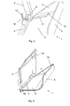
- Fig. 1 is the arrangement of the holder according to the invention and the bottle in a perspective overall view of the passenger footwell, in Fig. 2 the same arrangement of the holder but without the bottle, in Fig. 3 in a perspective view of the detail of the holder in the execution with a spring and in Fig. 4 shown in perspective view of the holder in the embodiment with locking elements.
- FIG. 1 the space is shown in front of the passenger seat, where the center console 8 of the vehicle is arranged.
- a hinged holder 1 is inserted and secured in this center console 8, in which a bottle 6 can be inserted.
- This foldable bottle holder 1 serves to receive a drinking vessel for the needs of the vehicle occupants.
- the foldable holder 1 of the bottle 6 comprises a frame 2 and a pocket-shaped lid 3.
- the frame 2 is inserted into the center console 8 of the vehicle and secured thereto.
- a shaft 4 is arranged in the lower region of the frame 2.
- Another component of the holder 1 of the bottle 6 is the pocket-shaped lid 3, which is pivotally mounted to the shaft 4 of the frame 2.
- the bag-shaped lid 3 comprises a hinged, arc-like wall 5 and rear support wall 7.
- the hinged wall 5 has an open upper portion of the holder, ie the hinged wall 5 is with the arcuate profile for inserting and holding the bottle in the hinged holder first is formed and configured in the unfolded position.
- the bottle bottom 6 leans. After removal of the bottle 6 from the folding holder 1, according to Fig. 2 , the bag-shaped lid 3 folds toward the frame 2 of the hinged holder 1 and the bag-shaped lid 3 is thus in the closed position.
- a compression spring 9 is fixed, which has two elongated legs.
- the first leg 10 of the spring 9 is secured in the recess 13 of the frame and leans against this frame 2 of the hinged holder 1.
- the second leg 11 is secured in the recess 12 which is formed in the pocket-shaped cover 3 of the hinged holder 1.
- the compression spring 9 can be arranged at each end of the shaft 4 mounted in the frame 2.
- this holder 1 After insertion of the bottle 6 in the hinged holder 1, this holder 1 is in the open position and under the influence of the bias of the compression spring 9 presses the bag-shaped lid 3 on the bottle 6. Thereby, the unwanted movement of the bottle 6 in hinged holder 1 avoided, which may be caused by the vibrations while driving.
- the pocket-shaped cover 3 After removal of the bottle 6 from the hinged holder 1, the pocket-shaped cover 3 is closed by the bias of the compression spring 9 to the frame 2 of the folding holder 1 and the bag-shaped cover 3 is thus in the closed position.
- FIG. 3 Another embodiment, according to Fig. 3 , represents the cheaper version with a locking tab 15 and with corresponding catch 14.
- This solution is designed so that the rear support wall 7 of the pocket-shaped lid 3 has a locking tab 15 and the frame 2 has a catch 14.
- the locking tab 15 and the catch 14 are formed so that the locking tab 15 of the rear support wall 7 of the pocket-shaped lid 3 engages exactly in the catch 14 of the frame 2.
- the pocket-shaped lid 3 folded toward the frame 2 is secured and held in the closed position.
- the pocket-shaped cover 3 has in the connecting region with the frame 2 a Aufsetzkante 16 which rests in the open position of the pocket-shaped lid 3 on the frame 2 of the folding holder 1 and is based on it.
- the spread width of the holder 1 in the open position is optimized and adapted to the diameter of the bottle to be used.
- the foldable holder 1 in the closed closed position of the pocket-shaped lid 3 is designed such that does not restrict the passenger footwell.
- the foldable bottle holder can be made of plastic and the bottle corresponds to a commercial PET bottle for drinks, as standard for various drinks such as sodas, mineral water, etc. in different volume sizes (0.5l, 1l, 1.5l, 2l, etc.). is used.
- the foldable bottle holder according to the invention can be used in all automobiles and advantageously arranged for example in the passenger compartment in front of the front seat and front portion of the center tunnel in the foot of the passenger and attached to the center console of the vehicle.
Abstract
Description
- Die Erfindung betrifft einen klappbaren Flaschenhalter, der im Fahrgastraum im Fußbereich des Beifahrers angeordnet und an der Mittelkonsole des Fahrzeuges befestigt ist, wobei der Flaschenhalter zur Aufbewahrung von Trinkflaschen oder beliebigen Gefäße für den Bedarf der Fahrzeuginsassen dient.
- Für die Befestigung verschiedener Flaschen und flaschenförmiger Gefäße im Fahrer- und Beifahrerbereich werden geläufig verschiedene Halterungen und komplizierte Befestigungssysteme verwendet. Diese Halterungen sind in überwiegender Mehrheit an der Schalttafel oder am Mitteltunnel zwischen dem Fahrer und dem Beifahrer angeordnet.
- Im Dokument
DE10223404A1 ist eine Haltevorrichtung für die Befestigung eines Trinkgefäßes im Fahrgastraum zwischen dem Fahrer- und Beifahrersitz angeführt, das beliebig am Mitteltunnel im Abschnitt zwischen der Schalttafel und den Fondsitzen befestigt werden kann. Zum Mitteltunnel ist in diesem Abschnitt ein Verbindungsteil befestigt, auf dem senkrecht zur Vertikale der Flaschenhalter frei aufgesetzt ist. Dieser Verbindungsteil kann auch zur Vorderseite des Fahrer- sowie Beifahrersitzrahmens im Fußbereich befestigt werden. Der Verbindungsteil umfasst eine ringförmige Aufnahme. Der Flaschenhalter umfasst einen Haltearm, auf dem ein ausfahrbarer Bolzen befestigt ist. Die eigentliche Verbindung des Flaschenhalters mit dem Verbindungsteil ist derart ausgeführt, dass der ausfahrbare Bolzen des Flaschenhalters in die ringförmige Aufnahme des Verbindungsteils eingesteckt wird. - Die Halterungen verschiedener Trinkgefäße werden auch an die Mittelkonsole, im ihren unteren Abschnitt, im Fußraum der Fahrzeuginsassen angeordnet. Solche Anordnung einer Halterung ist im
DE102004005053 angeführt. In diesem Dokument ist eine Lösung der Halterung zum lösbaren Halten insbesondere dann der Flaschen im Fahrzeuginnenraum beschrieben, die an der Mittelkonsole befestigt ist. Die Halterung umfasst einen Halteteil, welcher die Flasche im Halsbereich hält und die Form eines Hakens oder einer Backe hat. Im Bodenbereich wird die Flasche mit einer Stützeinheit gehalten, die an der Mittelkonsole als ein verschiebbarer Deckel ausgestaltet ist, welcher die Flasche unterstützt und fixiert. - Im Dokument
DE102007006898 ist eine Haltevorrichtung zur Aufnahme und Kühlung von Getränkebehältern in einem Kraftfahrzeug beschrieben, die ein an flexibler Wandung angebrachtes Gehäuse umfasst, welches einen Raum zur Aufnahme dieses Gefäßes aufweist und eine Kühleinrichtung einschl. einer Einrichtung für die Übertragung der Kälte von der Kühleinrichtung auf den Getränkebehälter umfasst. Diese flexible Wandung ist an der Verkleidung der Mittelkonsole im Beifahrerfußraum im Fahrzeug angeordnet. - Der Nachteil solcher Lösungen liegt darin, dass beim Nichtgebrauch der Halterung diese ständig in den Fußraum der Insassen herausragt und so den Raum für Beifahrer einschränkt oder sogar einen Schaden an der Kleidung oder eine Verletzung verursachen kann.
- Die Aufgabe wird mit einem klappbaren Flaschenhalter gelöst, der im Fahrzeuginnenraum vor dem Vordersitz im Fußraum der Insassen angeordnet und an der Mittelkonsole des Fahrzeuges befestigt ist. Dieser klappbarer Flaschenhalter dient zur Aufnahme eines dem Bedarf der Fahrzeuginsassen dienenden Gefäßes. Die Darstellung der Erfindung liegt darin, dass der Flaschenhalter durch einen Rahmen gebildet wird, der an der Mittelkonsole des Fahrzeuges eingesetzt und befestigt ist. Der Rahmen weist im seinen unteren Bereich eine Welle auf. Der Flaschenhalter umfasst weiter einen taschenförmigen Deckel, der mit dem Rahmen über eine schwenkbare Befestigung mit der Welle des Rahmens verbunden ist. Der taschenförmige Deckel wird durch eine klappbare, bogenartige Wand gebildet, die für das Einsetzen und Halten der Flasche im klappbaren Halter in der aufgeklappten Position gebildet und ausgestaltet ist. Der taschenförmige Deckel umfasst weiter eine hintere Stützwand, an der sich der Flaschenboden abstützt. Nach der Entnahme der Flasche aus dem klappbaren Halter wird der taschenförmige Deckel zum Rahmen des klappbaren Halters zugeklappt und so befindet sich der taschenförmige Deckel in der geschlossenen Position.
- Auf der Welle des Rahmens ist eine Druckfeder befestigt, die zwei verlängerte Schenkel aufweist. Der erste Schenkel der Feder ist in der Aussparung des Rahmens befestigt und stützt sich an dem Halterrahmen ab und der zweite Schenkel ist in dem Einschnitt befestigt, der im taschenförmigen Deckel ausgebildet ist. Durch die Vorspannung der Druckfeder wird der taschenförmige Deckel zum Rahmen gedrückt.
- Der taschenförmige Deckel kann auch eine Sperrlasche umfassen. Der Rahmen weist in diesem Fall eine Raste auf. Die Sperrlasche und die Raste sind so ausgebildet, dass die Sperrlasche der hinteren Stützwand des Deckels genau in die Raste des Rahmens eingreift und so den taschenförmigen, zum Rahmen zugeklappten Deckel in der geschlossenen Stellung sichert und hält. Der taschenförmige Deckel weist im Verbindungsbereich mit dem Rahmen eine Aufsetzkante auf, die in der offenen Stellung des taschenförmigen Deckels auf den Rahmen des klappbaren Halters aufsetzt und sich an ihm anlehnt.
- Im Gegensatz zum oben genannten Stand der Technik schränkt der vorliegende klappbare Halter in der zugeklappten geschlossenen Stellung des Deckels den Beifahrerfußraum nicht ein.
- In der
Fig. 1 ist die Anordnung des erfindungsgemäßen Halters und der Flasche in einer perspektivischen Gesamtansicht des Beifahrerfußraumes, inFig. 2 die gleiche Anordnung des Halters jedoch ohne der Flasche, inFig. 3 in einer perspektivischen Ansicht das Detail des Halters in der Ausführung mit einer Feder und inFig. 4 in perspektivischer Ansicht der Halter in der Ausführung mit Sperrelementen dargestellt. - In der
Fig. 1 ist der Raum vor dem Beifahrersitz abgebildet, wo die Mittelkonsole 8 des Fahrzeuges angeordnet ist. An dieser Stelle ist in diese Mittelkonsole 8 ein klappbarer Halter 1 eingesetzt und befestigt, in den eine Flasche 6 eingelegt werden kann. Dieser klappbarer Flaschenhalter 1 dient zur Aufnahme eines Trinkgefäßes für den Bedarf der Fahrzeuginsassen. Der klappbarer Halter 1 der Flasche 6 umfasst einen Rahmen 2 und einen taschenförmigen Deckel 3. Der Rahmen 2 ist in der Mittelkonsole 8 des Fahrzeuges eingesetzt und zu dieser befestigt. Im unteren Bereich des Rahmens 2 ist eine Welle 4 angeordnet. Weiterer Bestandteil des Halters 1 der Flasche 6 ist der taschenförmige Deckel 3, der schwenkbar zu der Welle 4 des Rahmens 2 befestigt ist. Der taschenförmige Deckel 3 umfasst eine klappbare, bogenartige Wand 5 und hintere Stützwand 7. Die klappbare Wand 5, hat einen offenen oberen Abschnitt des Halters, d.h. die klappbare Wand 5 ist mit dem bogenartigen Profil für das Einsetzen und Halten der Flasche im klappbaren Halter 1 in der aufgeklappten Position gebildet und ausgestaltet ist. An die hintere Stützwand 7 des taschenförmigen Deckels 3 lehnt sich der Flaschenboden 6 an. Nach der Entnahme der Flasche 6 aus dem klappbaren Halter 1, gemäßFig. 2 , klappt der taschenförmige Deckel 3 zum Rahmen 2 des klappbaren Halters 1 zu und der taschenförmige Deckel 3 befindet sich somit in der geschlossenen Stellung. - Ein Ausführungsbeispiel für die geschlossene Stellung des klappbaren Halters 1 der Flasche 6, gemäß
Fig. 3 , ist die Ausführung mit einer Druckfeder 9. Auf der Welle 4 des Rahmens 2 ist eine Druckfeder 9 befestigt, die zwei verlängerte Schenkel aufweist. Der erste Schenkel 10 der Feder 9 ist in der Aussparung 13 des Rahmens befestigt und lehnt sich an diesen Rahmen 2 des klappbaren Halters 1 an. Der zweite Schenkel 11 ist in dem Einschnitt 12 befestigt, der im taschenförmigen Deckel 3 des klappbaren Halters 1 ausgebildet ist. Durch die Vorspannung der Druckfeder 9 wird der taschenförmige Deckel 3 zum Rahmen 2 gedrückt. Vorteilhaft kann die Druckfeder 9 an jedem Ende der im Rahmen 2 gelagerten Welle 4 angeordnet werden. - Nach dem Einsetzen der Flasche 6 in den klappbaren Halter 1 ist dieser Halter 1 in der offenen Stellung und unter dem Einfluss der Vorspannung der Druckfeder 9 drückt der taschenförmige Deckel 3 auf die Flasche 6. Dadurch wird die unerwünschte Bewegung der Flasche 6 im klappbaren Halter 1 vermieden, die durch die Schwingungen während der Fahrt entstehen kann. Nach der Entnahme der Flasche 6 aus dem klappbaren Halter 1 wird durch die Vorspannung der Druckfeder 9 der taschenförmige Deckel 3 zum Rahmen 2 des klappbaren Halters 1 zugeklappt und der taschenförmige Deckel 3 befindet sich somit in der geschlossenen Stellung.
- Ein weiteres Ausführungsbeispiel, gemäß
Fig. 3 , stellt die billigere Ausführung mit einer Sperrlasche 15 und mit korrespondierender Raste 14 dar. Diese Lösung ist so ausgeführt, dass die hintere Stützwand 7 des taschenförmigen Deckels 3 eine Sperrlasche 15 und der Rahmen 2 eine Raste 14 aufweist. Die Sperrlasche 15 und die Raste 14 sind so ausgebildet, dass die Sperrlasche 15 der hinteren Stützwand 7 des taschenförmigen Deckels 3 genau in die Raste 14 des Rahmens 2 eingreift. Somit wird der zum Rahmen 2 zugeklappte taschenförmige Deckel 3 in der geschlossenen Position gesichert und gehalten. Der taschenförmige Deckel 3 weist im Verbindungsbereich mit dem Rahmen 2 eine Aufsetzkante 16 auf, die in der offenen Stellung des taschenförmigen Deckels 3 auf den Rahmen 2 des klappbaren Halters 1 aufsetzt und sich an ihm anlehnt. Die Spreizbreite des Halters 1 in offener Stellung ist optimiert und dem Durchmesser der einzusetzenden Flasche angepasst. - Vorteilhaft können bei dieser Ausführung mehrere am Umlauf des taschenförmigen Deckels 3 beliebig angeordnete Sperrlaschen 15 und dazu an korrespondierenden Stellen die entsprechende Anzahl der Rasten 14 eingesetzt werden.
- Der klappbare Halter 1 in der zugeklappten geschlossenen Stellung des taschenförmigen Deckels 3 ist derart ausgestaltet, dass der den Beifahrerfußraum nicht einschränkt.
- Der klappbare Flaschenhalter kann aus Kunststoff ausgebildet sein und die Flasche entspricht einer handelsüblichen PET-Flasche für Getränke, wie diese standardmäßig für verschiedene Getränke wie Limonaden, Mineralwasser usw. in verschiedenen Volumengrößen (0,5l; 1l; 1,5l; 2l usw.) verwendet wird.
- Der erfindungsgemäße klappbare Flaschenhalter kann in allen Automobilen eingesetzt werden und vorteilhaft beispielsweise im Fahrgastraum vor dem Vordersitz und vorderen Abschnitt des Mitteltunnels im Fußbereich des Beifahrers angeordnet und an der Mittelkonsole des Fahrzeuges befestigt werden.
-
- 1
- klappbarer Flaschenhalter
- 2
- Rahmen des Halters
- 3
- taschenförmiger Deckel des Halters
- 4
- Welle des Rahmens
- 5
- klappbare Wand des taschenförmigen Deckels
- 6
- Flasche
- 7
- hintere Stützwand des taschenförmigen Deckels
- 8
- Mittelkonsole des Fahrzeuges
- 9
- Druckfeder
- 10
- erster Federschenkel
- 11
- zweiter Federschenkel
- 12
- Einschnitt im taschenförmigen Deckel
- 13
- Aussparung im Rahmen
- 14
- Raste im Rahmen
- 15
- Sperrlasche der hinteren Stützwand
- 16
- Aufsetzkante des taschenförmigen Deckels
Claims (4)
- Ein im Fahrgastraum vor dem Vordersitz im Fußraum der Insassen angeordneter und an der Mittelkonsole (8) des Fahrzeuges befestigter klappbarer Halter (1) einer Flasche (6), wobei der klappbare Halter (1) der Flasche (6) zur Aufbewahrung von Trinkflaschen oder beliebigen Gefäße für den Bedarf der Fahrzeuginsassen dient, dadurch gekennzeichnet, dass- der Halter (1) der Flasche (6) umfasst
einen an der Mittelkonsole (8) des Fahrzeuges eingesetzten und befestigten Rahmen (2), der in seinem unteren Abschnitt eine gelagerte Welle (4) aufweist,
sowie einen mit dem Rahmen (2) über eine schwenkbare Befestigung mit der Welle (4) verbundenen taschenförmigen Deckel (3), der durch eine bogenartige klappbare Wand (5), die für das Einsetzen und Halten der Flasche (6) im klappbaren Halter (1) in der aufgeklappten Position ausgestaltet ist und eine hintere Stützwand (7), an der sich der Boden der Flasche (6) abstützt, gebildet wird,
wobei nach der Entnahme der Flasche (6) aus dem klappbaren Halter (1) der taschenförmige Deckel (3) in der geschlossenen Stellung im Rahmen (2) des klappbaren Halters (1) angeordnet ist. - Ein klappbarer Halter (1) nach Anspruch 1 dadurch gekennzeichnet, dass an der Welle (4) mindestens eine Druckfeder (9) angeordnet ist, die einen ersten Schenkel (10) und einen zweiten Schenkel (11) aufweist, wobei der erste Schenkel (10) an die Aussparung (13) im Rahmens (2) des Halters (1) anlehnt und der zweite Schenkel (11) in den Einschnitt (12) eingreift, der an dem taschenförmigen Deckel (3) ausgebildet ist, wobei durch die Vorspannung der Feder (9) der taschenförmige Deckel (3) zum Rahmen (2) gedrückt wird.
- Ein klappbarer Halter (1) nach Anspruch 1 dadurch gekennzeichnet, dass der taschenförmige Deckel (3) mindestens eine Sperrlasche (15) und der Rahmen (2) mindestens eine Raste (14) aufweist, wobei die Sperrlasche (15) und die Raste (14) für genaues Einrasten der Sperrlasche (15) in die Raste (14) ausgestaltet sind, wodurch das Halten des taschenförmigen Deckels (3) am Rahmen (2) in geschlossener Stellung gesichert wird.
- Ein klappbarer Halter (1) nach Ansprüchen 1 und 3 dadurch gekennzeichnet, dass der taschenförmige Deckel (3) des klappbaren Halters (1) im Verbindungsbereich mit dem Rahmen (2) mindestens eine Aufsetzkante (16) aufweist, die in der offenen Stellung des taschenförmigen Deckels (3) an den Rahmen (2) anlehnt.
Applications Claiming Priority (1)
| Application Number | Priority Date | Filing Date | Title |
|---|---|---|---|
| CZ20100757A CZ2010757A3 (cs) | 2010-10-18 | 2010-10-18 | Sklopný držák láhve |
Publications (2)
| Publication Number | Publication Date |
|---|---|
| EP2441618A2 true EP2441618A2 (de) | 2012-04-18 |
| EP2441618A3 EP2441618A3 (de) | 2017-10-18 |
Family
ID=45002877
Family Applications (1)
| Application Number | Title | Priority Date | Filing Date |
|---|---|---|---|
| EP11466029.3A Withdrawn EP2441618A3 (de) | 2010-10-18 | 2011-10-13 | Klappbarer Flaschenhalter |
Country Status (2)
| Country | Link |
|---|---|
| EP (1) | EP2441618A3 (de) |
| CZ (1) | CZ2010757A3 (de) |
Citations (3)
| Publication number | Priority date | Publication date | Assignee | Title |
|---|---|---|---|---|
| DE10223404A1 (de) | 2001-07-26 | 2003-03-13 | Daimler Chrysler Ag | Vorrichtung zum Haltern von Getränkehaltern |
| DE102004005053A1 (de) | 2004-01-30 | 2005-08-18 | Reum Gmbh & Co. Betriebs Kg | Haltevorrichtung zum lösbaren Halten von Gegenständen |
| DE102007006898A1 (de) | 2007-02-13 | 2008-08-21 | Audi Ag | Vorrichtung zur Aufnahme und Kühlung von Getränkebehältern |
Family Cites Families (5)
| Publication number | Priority date | Publication date | Assignee | Title |
|---|---|---|---|---|
| DD147343A1 (de) * | 1979-10-30 | 1981-04-01 | Rolf Starec | Flaschensicherung fuer fahrzeuge |
| JP3644142B2 (ja) * | 1996-07-18 | 2005-04-27 | 日本プラスト株式会社 | カップホルダ |
| FR2863561B1 (fr) * | 2003-12-12 | 2006-02-03 | Renault Sas | Console de vehicule automobile pourvue d'un support de recipient |
| DE102005035273B4 (de) * | 2005-07-28 | 2010-07-01 | Daimler Ag | Haltevorrichtung |
| DE102007048033A1 (de) * | 2007-10-06 | 2009-04-09 | Fischer Automotive Systems Gmbh & Co. Kg | Halter für einen Getränkebehälter |
-
2010
- 2010-10-18 CZ CZ20100757A patent/CZ2010757A3/cs unknown
-
2011
- 2011-10-13 EP EP11466029.3A patent/EP2441618A3/de not_active Withdrawn
Patent Citations (3)
| Publication number | Priority date | Publication date | Assignee | Title |
|---|---|---|---|---|
| DE10223404A1 (de) | 2001-07-26 | 2003-03-13 | Daimler Chrysler Ag | Vorrichtung zum Haltern von Getränkehaltern |
| DE102004005053A1 (de) | 2004-01-30 | 2005-08-18 | Reum Gmbh & Co. Betriebs Kg | Haltevorrichtung zum lösbaren Halten von Gegenständen |
| DE102007006898A1 (de) | 2007-02-13 | 2008-08-21 | Audi Ag | Vorrichtung zur Aufnahme und Kühlung von Getränkebehältern |
Also Published As
| Publication number | Publication date |
|---|---|
| CZ2010757A3 (cs) | 2012-04-25 |
| EP2441618A3 (de) | 2017-10-18 |
Similar Documents
| Publication | Publication Date | Title |
|---|---|---|
| DE19609022C2 (de) | Abnehmbare Vorrichtung zum Halten von Getränkebehältern, Trinkgefäßen oder dergleichen, insbesondere in Kraftfahrzeugen | |
| DE202005003636U1 (de) | Vorrichtung zur Halterung von Gebrauchsgegenständen, beispielsweise Getränkebehältern | |
| DE102008026359A1 (de) | Ablagefach in einem Fahrzeug, insbesondere in einer Instrumententafel eines Fahrzeugs | |
| DE102014113532A1 (de) | Sonnenblende für ein Fahrzeug | |
| EP2435273A1 (de) | Haltevorrichtung, insbesondere für getränkebehälter | |
| DE102014109263A1 (de) | Sonnenblende für ein Fahrzeug | |
| DE102006061615B4 (de) | Aufnahmevorrichtung für ein Zubehörteil in einem Kraftfahrzeug | |
| DE202004008205U1 (de) | DVD-Unterhaltungseinrichtung für ein Kraftfahrzeug | |
| EP2441618A2 (de) | Klappbarer Flaschenhalter | |
| DE102019102721B4 (de) | Abdecksystem für eine fahrzeugtürtasche, fahrzeugtür mit solch einem abdecksystem und einbauverfahren eines ab-decksystems für eine fahrzeugtürtasche | |
| DE102014016230B4 (de) | Ablagefach eines Fahrzeugs | |
| DE102008022417A1 (de) | Multifunktionsablage | |
| DE4327716C1 (de) | Halter für einen Trinkbehälter | |
| EP2452852A2 (de) | Schwenkbarer Flaschenhalter | |
| DE102004029003B4 (de) | Cupholder | |
| DE102016008235A1 (de) | Airbaganordnung für ein Fahrzeug | |
| DE202009000895U1 (de) | Einstellbare Halteeinrichtung für Bordcomputer in Kraftfahrzeugen | |
| DE102004005053A1 (de) | Haltevorrichtung zum lösbaren Halten von Gegenständen | |
| EP2447114A2 (de) | Flaschenhalter in einem Fahrzeug | |
| DE102017010671A1 (de) | Multifunktionstischanordnung und Kraftfahrzeug mit einer solchen Multifunktionstischanordnung | |
| DE102008030219A1 (de) | Halterung für Gegenstände | |
| DE102017008726B4 (de) | Getränkehalter mit Doppelflügel | |
| DE102019007560A1 (de) | Sonnenblende für ein Kraftfahrzeug | |
| DE102009054307A1 (de) | Haltevorrichtung für die Halterung von Gegenständen im Innenraum eines Kraftfahrzeugs sowie Anordnung der Haltevorrichtung in dem Innenraum | |
| DE102006002809A1 (de) | Kraftfahrzeuginneneinrichtung mit einem Ablagefach in der Mittelkonsole |
Legal Events
| Date | Code | Title | Description |
|---|---|---|---|
| PUAI | Public reference made under article 153(3) epc to a published international application that has entered the european phase |
Free format text: ORIGINAL CODE: 0009012 |
|
| AK | Designated contracting states |
Kind code of ref document: A2 Designated state(s): AL AT BE BG CH CY CZ DE DK EE ES FI FR GB GR HR HU IE IS IT LI LT LU LV MC MK MT NL NO PL PT RO RS SE SI SK SM TR |
|
| AX | Request for extension of the european patent |
Extension state: BA ME |
|
| PUAL | Search report despatched |
Free format text: ORIGINAL CODE: 0009013 |
|
| AK | Designated contracting states |
Kind code of ref document: A3 Designated state(s): AL AT BE BG CH CY CZ DE DK EE ES FI FR GB GR HR HU IE IS IT LI LT LU LV MC MK MT NL NO PL PT RO RS SE SI SK SM TR |
|
| AX | Request for extension of the european patent |
Extension state: BA ME |
|
| RIC1 | Information provided on ipc code assigned before grant |
Ipc: B60N 3/10 20060101AFI20170914BHEP |
|
| 17P | Request for examination filed |
Effective date: 20180418 |
|
| RBV | Designated contracting states (corrected) |
Designated state(s): AL AT BE BG CH CY CZ DE DK EE ES FI FR GB GR HR HU IE IS IT LI LT LU LV MC MK MT NL NO PL PT RO RS SE SI SK SM TR |
|
| STAA | Information on the status of an ep patent application or granted ep patent |
Free format text: STATUS: THE APPLICATION IS DEEMED TO BE WITHDRAWN |
|
| 18D | Application deemed to be withdrawn |
Effective date: 20180419 |