EP2438428B1 - Abbildende system mit microlinsen für probenmessung - Google Patents
Abbildende system mit microlinsen für probenmessung Download PDFInfo
- Publication number
- EP2438428B1 EP2438428B1 EP10734785.8A EP10734785A EP2438428B1 EP 2438428 B1 EP2438428 B1 EP 2438428B1 EP 10734785 A EP10734785 A EP 10734785A EP 2438428 B1 EP2438428 B1 EP 2438428B1
- Authority
- EP
- European Patent Office
- Prior art keywords
- sample
- imaging system
- photosensors
- microlenses
- lamina
- Prior art date
- Legal status (The legal status is an assumption and is not a legal conclusion. Google has not performed a legal analysis and makes no representation as to the accuracy of the status listed.)
- Active
Links
Images


Classifications
-
- G—PHYSICS
- G02—OPTICS
- G02B—OPTICAL ELEMENTS, SYSTEMS OR APPARATUS
- G02B3/00—Simple or compound lenses
- G02B3/0006—Arrays
- G02B3/0037—Arrays characterized by the distribution or form of lenses
- G02B3/0056—Arrays characterized by the distribution or form of lenses arranged along two different directions in a plane, e.g. honeycomb arrangement of lenses
-
- C—CHEMISTRY; METALLURGY
- C12—BIOCHEMISTRY; BEER; SPIRITS; WINE; VINEGAR; MICROBIOLOGY; ENZYMOLOGY; MUTATION OR GENETIC ENGINEERING
- C12M—APPARATUS FOR ENZYMOLOGY OR MICROBIOLOGY; APPARATUS FOR CULTURING MICROORGANISMS FOR PRODUCING BIOMASS, FOR GROWING CELLS OR FOR OBTAINING FERMENTATION OR METABOLIC PRODUCTS, i.e. BIOREACTORS OR FERMENTERS
- C12M23/00—Constructional details, e.g. recesses, hinges
- C12M23/02—Form or structure of the vessel
- C12M23/12—Well or multiwell plates
-
- C—CHEMISTRY; METALLURGY
- C12—BIOCHEMISTRY; BEER; SPIRITS; WINE; VINEGAR; MICROBIOLOGY; ENZYMOLOGY; MUTATION OR GENETIC ENGINEERING
- C12M—APPARATUS FOR ENZYMOLOGY OR MICROBIOLOGY; APPARATUS FOR CULTURING MICROORGANISMS FOR PRODUCING BIOMASS, FOR GROWING CELLS OR FOR OBTAINING FERMENTATION OR METABOLIC PRODUCTS, i.e. BIOREACTORS OR FERMENTERS
- C12M41/00—Means for regulation, monitoring, measurement or control, e.g. flow regulation
- C12M41/30—Means for regulation, monitoring, measurement or control, e.g. flow regulation of concentration
- C12M41/36—Means for regulation, monitoring, measurement or control, e.g. flow regulation of concentration of biomass, e.g. colony counters or by turbidity measurements
-
- G—PHYSICS
- G01—MEASURING; TESTING
- G01N—INVESTIGATING OR ANALYSING MATERIALS BY DETERMINING THEIR CHEMICAL OR PHYSICAL PROPERTIES
- G01N21/00—Investigating or analysing materials by the use of optical means, i.e. using sub-millimetre waves, infrared, visible or ultraviolet light
- G01N21/62—Systems in which the material investigated is excited whereby it emits light or causes a change in wavelength of the incident light
- G01N21/63—Systems in which the material investigated is excited whereby it emits light or causes a change in wavelength of the incident light optically excited
- G01N21/64—Fluorescence; Phosphorescence
- G01N21/645—Specially adapted constructive features of fluorimeters
- G01N21/6456—Spatial resolved fluorescence measurements; Imaging
-
- G—PHYSICS
- G01—MEASURING; TESTING
- G01N—INVESTIGATING OR ANALYSING MATERIALS BY DETERMINING THEIR CHEMICAL OR PHYSICAL PROPERTIES
- G01N21/00—Investigating or analysing materials by the use of optical means, i.e. using sub-millimetre waves, infrared, visible or ultraviolet light
- G01N21/62—Systems in which the material investigated is excited whereby it emits light or causes a change in wavelength of the incident light
- G01N21/63—Systems in which the material investigated is excited whereby it emits light or causes a change in wavelength of the incident light optically excited
- G01N21/64—Fluorescence; Phosphorescence
- G01N21/645—Specially adapted constructive features of fluorimeters
- G01N21/6456—Spatial resolved fluorescence measurements; Imaging
- G01N21/6458—Fluorescence microscopy
-
- G—PHYSICS
- G01—MEASURING; TESTING
- G01N—INVESTIGATING OR ANALYSING MATERIALS BY DETERMINING THEIR CHEMICAL OR PHYSICAL PROPERTIES
- G01N33/00—Investigating or analysing materials by specific methods not covered by groups G01N1/00 - G01N31/00
- G01N33/48—Biological material, e.g. blood, urine; Haemocytometers
- G01N33/483—Physical analysis of biological material
- G01N33/487—Physical analysis of biological material of liquid biological material
-
- G—PHYSICS
- G02—OPTICS
- G02B—OPTICAL ELEMENTS, SYSTEMS OR APPARATUS
- G02B21/00—Microscopes
- G02B21/0004—Microscopes specially adapted for specific applications
- G02B21/0008—Microscopes having a simple construction, e.g. portable microscopes
Definitions
- the present invention relates to a microlens imaging system and associated device for the detection and optical characterization of a sample.
- the invention applies in the field of the miniaturization of measuring instruments for chemical or biological analysis.
- a microscope comprises optical lenses (objective, eyepiece), a light source and at least one photosensor.
- the microscopes used daily by researchers are often expensive and restrictive, in particular because of their spatial bulk. Usually, they do not allow images to be produced continuously over time or at predefined times.
- One of the ways of miniaturization currently envisaged is to eliminate the magnification objectives of the microscope and to produce the image of the shadow or the diffraction pattern created on the sensitive surface of the photosensors.
- the image formed by the shadow or the diffraction pattern of the object observed in contact with the photosensors is called a photogram.
- a priori the resolution, defined as the ability to distinguish two very close disks, is in this type of system limited by the size of the pixels and the object / surface distance of the optical sensor. While in a conventional microscope, it is limited by diffraction in the objective lens system.
- the images acquired by such an imaging system show neither the morphology nor the shape in the case where the cells of the sample to be analyzed are adherent.
- the cells in suspension or adhered do not correspond to the same challenge: the cells are objects of low contrast with the culture medium because the optical indices are similar. When adhered, they exhibit a flat, elongated shape, which makes them more difficult to image.
- the aim of the invention is to provide a device of reduced size capable of imaging cells, in particular adherent cells, in order to locate and identify cells, enumerate them and analyze their morphology.
- the small size of the device makes it possible to introduce it directly into an incubator in order to allow proliferation of the cells of the sample.
- the subject of the invention is a system for imaging a sample comprising the characteristics of claim 1.
- the system for imaging a sample comprises one or more of the characteristics of claims 2 to 15.
- this imaging system of reduced size is able to produce images of cells continuously over time or at predefined times in order to quantify the proliferation of cells, individually follow their movement and deduce their trajectory and speed, detect cell divisions and establishing filiations, highlighting and quantifying changes in morphology, identifying cellular events of interest (rare events, etc.).
- the subject of the invention is also a device for detecting and characterizing a sample according to claim 16.
- the device for detecting and characterizing a sample comprises one or more of the characteristics of claims 17 to 19.
- the invention relates to a device 2 for detecting and characterizing a sample 4, an embodiment of which is illustrated in FIG. figure 1 .
- Sample 4 comprises objects 5 to be detected and imaged in order to study their characteristics (morphology, size, etc.).
- the objects 5 are objects of micrometric size (bacteria, yeasts, fungi, pollens, algae, liposomes, etc.) and preferably cells.
- the device 2 comprises at least one imaging system 6 intended to detect and characterize the sample 4 and an electronic controller 8 capable of controlling the imaging system 6.
- the electronic controller 8 comprises a support capable of fixing the system of. imaging 6, for example to plug it in if it includes connection plugs.
- the imaging system 6 is described in detail below.
- the device 2 further comprises a computer system 10 intended to control the electronic controller 8 to which it is connected.
- the computer system 10 comprises a man / machine interface 12 intended to enter information to control the electronic controller 8 and to display information relating to the sample 4.
- the computer system 10 further comprises a calculation unit capable of carrying out processing operations on the images and a storage unit for recording the images acquired of the sample.
- the device 2 comprises an incubation chamber or incubator 14 and means 16 for controlling and regulating the level of CO 2 , the humidity and the temperature inside the incubation chamber.
- the incubator 14 is a standard incubator for cell biology, of dimensions of the order of a cubic meter in a known manner, which may optionally contain several imaging systems 6, or a miniaturized incubator of the dimensions of a system of. Imaging 6.
- the device 2 is easily transportable to be used, for example, near a place of collection of the sample.
- the imaging system 6, the electronic controller 8 and the sample 4 are placed inside the incubation chamber 14.
- the imaging system 6 comprises an optical system 17 intended to analyze the sample 4 and, preferably, the imaging system 6 comprises at least one light source 18 intended to illuminate the sample 4, the latter being arranged between the light source 18 and the optical system 17.
- the light source 18 is located opposite the optical system 17 in order to produce an image in transmission of the sample and at a controlled distance, for example at a distance of a few centimeters.
- the light source 18 is located vertically from the optical system 17.
- the light source 18 is offset with respect to the vertical of the optical system 17, for example at a distance of a few centimeters in an arc of a circle around the optical system 17.
- the light source is not or weakly collimated with a limiting illumination angle of less than 20 °, for example 10 °.
- the light source can be collimated by a system of lenses, diaphragms and / or directional filters or not, polychromatic or monochromatic, polarized or not, extent or point.
- the light source 18 is able to illuminate with a wavelength of between 200 nm and 800 nm, that is to say emitting in the visible and / or the near ultraviolet (UV).
- a wavelength of between 200 nm and 800 nm that is to say emitting in the visible and / or the near ultraviolet (UV).
- UV near ultraviolet
- white light that is to say light emitting a continuous spectrum of wavelength, in particular in the visible range (400 nm to 800 nm).
- the light source 18 comprises a light emitting diode (LED or LED in English), for example, a white LED, an array of LEDs, an incandescent bulb, or an electroluminescent sheet or a flat LED such as a commercial XLamp. by Cree (Durham, USA).
- LED light emitting diode
- Cree Cree (Durham, USA).
- the light source 18 comprises an illumination device of the Kölher type, that is to say an imaging system commonly used in optical microscopes for the illumination of the object or sample.
- Means 20 for controlling the light source 18 are integrated into the device 2 and connected to the computer system 10.
- the light source 18 is positioned above the optical system 17 so that it illuminates the sample at a specific angle (lighting angle) controlled by the operator or by the computer system 10.
- the light source 18 illuminates the object or sample at an intensity and / or for durations and / or at times specified by the operator or by the computer system 10.
- the light source 18 can be common to several samples or only illuminate a single sample.
- the imaging system 6 is connected to the electronic controller 8, for example by inserting the optical system 17 on the support of the device. electronic controller 8.
- the assembly comprising the optical system 17, the sample 4, the electronic controller 8 and the light source 18, is placed in the incubation chamber 14, in particular to allow the normal proliferation of the cell population.
- the incubator 14 regulates the temperature and the level of CO 2 , and maintains a high level of humidity thanks to the control and regulation means 16 previously set by the operator.
- this assembly (imaging system 6 including the light source 18, sample 4 and electronic controller 8) is preferably placed in a dark room in order to reduce parasitic noise associated with ambient lighting.
- the operator enters information through the man / machine interface 12 to adjust the or each light source 18 via the lighting control means 20 and to control the optical system 17 of the imaging system 6 via of the electronic controller 8.
- the operator thus controls remotely, thanks to the computer system 10, the or each imaging system 6, including the or each light source 18.
- the or each light source 18 illuminates the sample 4.
- the light or optical signal (photons) transmitted by the sample 4 is transformed by the optical system 17 of the imaging system 6 into an electrical signal.
- the electrical signal is then transmitted by the electronic controller 8 to the computer system 10.
- the data acquired by the optical system 17 of the imaging system 6 are recorded in the storage unit of the computer system 10. Then, the calculation unit reconstructs the image or sequence of images of the cells 5 of the sample. 4 from the data. Indeed, the device records in a known manner, dynamic events, either by carrying out a continuous acquisition (video mode) to obtain a film, or by acquiring images at regular intervals (photo mode) to obtain a sequence of images, and not only the intensity of the optical signal detected in transmission of the sample.
- the operator controls, via the man / machine interface 12, the calculation unit to carry out other processing of the image or sequence of images in order to characterize the sample 4.
- the unit calculator can spatially locate cells 5 of the sample, identify cells 5 based on analysis of their morphology and / or fluorescent signals and / or specific luminescent agents, count the cells, compare their position with their previous position, record the trajectory and speed of migration of each cell, quantify the proliferation of cells, characterize the morphology of each cell (calculation of the perimeter and the area covered by each cell, criterion of roundness of each cell, texture of the outline), highlight morphological changes on individual cells or a population of cells, segment the image to draw the junctions between cells and calculate the number of cells neighbors, detecting events of interest such as cell divisions or differentiations or calcium bursts , establishing filiations, and / or locating organelles (nuclei, etc.) in cells.
- it can eliminate background noise, for example by producing for each experiment an image in bright background (stray light)
- the device 2 is used without any light source 18.
- the analyzes need to be carried out in total darkness ( in darkroom).
- the intensity of the luminescence is integrated for a period determined by the operator in order to increase the sensitivity of the measurement, for example the integration time of the luminescence is 5 min.
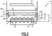
- the figure 2 is a schematic sectional view of the optical system 17 of the imaging system 6 intended to detect and characterize the sample 4.
- the sample 4 comprises objects, for example cells 5 and preferably adhered biological cells 22 in an aqueous medium, in a known manner a culture medium.
- the optical system 17 of the imaging system 6 comprises a matrix 24 of photosensors 26, regularly arranged, of which the photosensitive zone of each photosensor 26 is for example made of silicon.
- the optical system 17 further comprises a first transparent lamella 28 disposed opposite the array 24 of photosensors 26 defining a face 28A for supporting the sample 4.
- the face 28A is preferably flat and transparent.
- the first coverslip 28 has a specific surface treatment to capture and / or promote the adhesion of the cells 22 on the support face 28A of the sample 4, in a known manner by a method of functionalization with appropriate proteins, preferably proteins of the extracellular matrix, for example fibronectin, or with an oxygen plasma.
- appropriate proteins preferably proteins of the extracellular matrix, for example fibronectin, or with an oxygen plasma.
- Another surface treatment prevents adhesion on the face 28B opposite to the face 28A, support for the sample, for example by using polylysine-PEG (polylysine-polyethylene glycol) which gives it properties of hydrophobicity.
- polylysine-PEG polylysine-polyethylene glycol
- the support face 28A of the adhered cells 22 has a surface treatment to increase the adhesion of the cells thereon and the other face 28B has a surface treatment to reduce or eliminate the adhesion of the cells 22.
- the first coverslip 28 serves as a support for the cell culture.
- the first lamella 28 has good qualities in terms of optical transmission, for example it is made of glass or of polystyrene.
- the optical system 17 of the imaging system 6 further comprises an assembly 30 of optical elements disposed between the array 24 of photosensors 26 and the first lamella 28.
- the assembly 30 of optical elements comprises a separator element 37 located opposite and in contact with the matrix 24 of photosensors, and a matrix 32 of microlenses 34 arranged between the separator element 37 and the first lamella 28.
- the array 32 of microlenses 34 is positioned above the array 24 of photosensors 26 such that a microlens is located above each photosensor 26 of the array 24 of photosensors.
- each microlens 34 is associated with a photosensor 26.
- the optical axis of each microlens 34 is substantially coincident with the optical axis of a photosensor 26.
- the optical axis of a microlens 34 and the optical axis of a photosensor 26 may be slightly offset, the offset (angular or in distance) being less than or equal to 20%. This shift is either unintentional resulting from a difficulty in aligning the array of microlenses with the array of microlenses. photosensors, or voluntary in order to reorient an oblique incident optical beam towards the photosensor thanks to the microlens.
- Separator element 37 is formed from one or more optically transparent materials, for example, filters or passivation layers.
- the function of the separator element is to move the array 24 of photosensors 26 away from the array 32 of microlenses 34 so that the light rays are concentrated or focused towards the photosensors.
- the assembly 30 of optical elements further comprises a first medium 36, of refractive index or optical index n, arranged between the array 32 of microlenses and the first lamella 28.
- the first optical medium 36 is intended to modify the focal length of each microlens 34.
- the refractive index of the first optical medium 36 is substantially between 1 and the refractive index of the microlenses 34.
- the medium 36 is a gel or a liquid, for example an oil.
- the optical system 17 of the imaging system 6 further comprises a second coverslip 40 arranged such that the cells 22 are located between the first coverslip 28 and the second coverslip 40 in a second medium 42 delimited by the two coverslips 28, 40.
- the second sipe 40 has a surface treatment among those already described for the first sipe 28.
- the second medium 42 comprises a liquid, for example a biological liquid suitable for cell culture such as conventionally DMEM (for “ Dulbecco's Modified Eagle's Medium ”) or a saline solution such as a phosphate buffered saline or PBS (for “ Phosphate Buffered Saline ”.
- DMEM for “ Dulbecco's Modified Eagle's Medium”
- saline solution such as a phosphate buffered saline or PBS (for “ Phosphate Buffered Saline ”.
- the level of the liquid of the second medium is such that it covers the support face 28A of the sample 4 and the objects 22.
- the first medium 36 is a liquid similar to that of the second medium 42.
- the optical system 17 of the imaging system 6 comprises a sealed cuvette 38 in which the array 30 of optical elements are placed, the first coverslip 28, sample 4 so as to contain the liquids or gels of the first medium 36 and / or of the second medium 42.
- the bottom of the cuvette 38 may coincide with the surface of the photosensors 26.
- the cuvette 38 is drilled at the bottom and glued with the matrix 24 of photosensors 26 in order to guarantee the seal thanks to a biocompatible glue.
- the optical system 17 of the imaging system 6 further comprises separation means 43 capable of separating the first medium 36 from the second medium 42 if the latter are different. These separation means 43 are fixed to the walls of the bowl 38 or to the first strip 28.
- the distance measured along the optical axis Z between the first coverslip 28 and the second coverslip 40 is adjusted in order to obtain, in a known manner, a so-called configuration between slide and coverslip of sample 4.
- the second coverslip 40 is in this configuration in contact with sample 4.
- the second coverslip 40 can promote gas exchange through the second coverslip 40, and / or prevent evaporation through the second coverslip 40 of a part of the second medium 42, for example of the culture medium and of the sample 4.
- the optical system 17 further comprises means 44 for adjusting the distances measured along the optical axis Z between the support face 28A of the sample of the first lamella 28 and the face of the photosensors 26 disposed opposite the first lamella 28 .
- these adjustment means 44 comprise at least one piezoelectric ceramic.
- the adjustment means 44 can be mechanically fixed to the bottom or to the edges of the cuvette 38 or to the support of the matrix 24 of photosensors 26.
- the first blade 28 is fixed at a fixed height to the walls of the cuvette 38 of the imaging system 6 by mechanical, electrostatic, magnetic or equivalent means.
- the first coverslip 28, and therefore the sample 4 and the objects 5, preferably adhered cells 22, can be removed from the optical system 17 of the imaging system 6, depending on the needs of the operator, for example for a characterization of the sample on another instrument or for additional treatment of the sample (coloring, labeling with a fluorophore, etc.).
- the first coverslip 28, and the sample or object, can likewise be repositioned in the imaging system 6.
- the manufacturer or the operator of the imaging system chooses the separator element 37 and the first slide 28 beforehand according to their optical characteristics ( materials, refractive index, thickness %) and the desired use / application.
- the array 32 of microlenses 34 is chosen taking into account the angle of the acceptance cone of the photosensors 26 which is controlled by the presence of the microlenses 34, in particular by the nature (refractive index) and the shape (radius of curvature) of each microlens 34.
- Each microlens 34 comprises a plane diopter and a convex diopter.
- the upper face facing the sample of the microlenses is the convex diopter similar to a spherical cap.
- the microlenses are made of polystyrene, polyimide, AZ4562 photoresist or the like, poly (dimethylsiloxane), SU-8, silicon oxide, boron phosphorus doped silicate glass (BPSG), or a transparent thermoplastic material such as polymethyl methacrylate (PMMA) or polycarbonate.
- each microlens 34 is less than 25 ⁇ m, preferably less than 10 ⁇ m, so as to limit the phenomena of optical cross-talk (or “optical cross-talk” in English) between the microlenses and the associated underlying photosensors.
- the opening diameter of each microlens is at least two times smaller than the smallest lateral dimension of a cell.
- the smallest lateral dimension of a cell is the smallest dimension of the cell passing through its center of gravity and measured in a plane perpendicular to the optical axis of the imaging system, i.e. in a plane parallel to the face 28A of the strip serving as a support for the cell.
- the distance between the optical axes of two neighboring closer microlenses is preferably less than at least 30% of the aperture diameter of a microlens.
- the opening diameter of a microlens is the diameter of the section of intersection of the plane diopter and the convex diopter forming the microlens.
- the photosensors 26 associated with the microlenses 34 are arranged so that an object 5, preferably a cell, is covered by at least two adjacent photosensors in a first direction and two other adjacent photosensors in a second direction perpendicular to the first direction.
- the image of a cell is produced by at least one matrix of 2 x 2 adjacent photosensors.
- the aperture diameter of each microlens is substantially between 0.7 and 10 ⁇ m, preferably between 0.7 ⁇ m and 3.0 ⁇ m, to image objects such as cells whose diameter is substantially between 20 and 30 ⁇ m.
- These values make it possible to avoid a discontinuity in the image of the objects, even if it means that the same portion of the cell contributes to the light intensity of two neighboring photosensors.
- Oversampling the object 5 is preferable to downsampling in order to produce good quality images of the cells.
- Each cell is thus represented in the image by at least 2 side pixels, preferably by at least 6 side pixels, so as to facilitate subsequent computer processing on the images of the cells: the more cells are represented by a large number of pixels, the more the operations of improvement of contrast, filtering and thresholding of intensity carried out during the computer processing of the images will conform to reality.
- the distance between the optical axes of two closer neighboring microlenses is less than 3.0 ⁇ m for microlenses of 10 ⁇ m in aperture diameter, less than 900 nm for microlenses of 3.0 ⁇ m in diameter of aperture, less than 210 nm for microlenses with an aperture diameter of 700 nm.
- the manufacturer or the operator chooses the first medium 36 as a function of its refractive index n in order to modify the focal length of the microlenses 34 and thus the acceptance angle of the photosensors 26.
- the light beams are deflected at the optical interface between the first optical medium 36 and each microlens 34 according to Descartes' law.
- the index of the first medium 36 also makes it possible to adjust the angle of the acceptance cone of the photosensors.
- the selection of the refractive index of the first medium 36 controls the position of the crossings of the acceptance cones of neighboring or adjacent photosensors.
- the angle of the acceptance cone of the photosensors 26 is increased, and consequently the position of the crossings of the acceptance cones of neighboring photosensors is reduced, increasing the refractive index n of the medium 36, and vice versa.
- the refractive index of the first medium 36 is substantially between 1 and the refractive index of the microlenses 34, preferably between 1 and 1.64.
- any optically active material located between the matrix of photosensors and the sample, participates in the modification of the acceptance cone of the photosensors.
- this is the case of the separator element 37 and of the first lamella 28.
- the light beams are deflected at the optical interface between the first lamella 28 and the first optical medium 36 according to the law of Descartes. Therefore the choice of the first slide also adjusts the acceptance cone of the photosensors.
- it is also chosen for its optical qualities (high transmission) and is used as a support for the objects 5 and preferably the adhered cells 22 to be imaged.
- the distance, measured along the optical axis Z, between the face 28A supporting the sample 4 of the first slide 28 and the top of the microlenses 34, is adjusted, and therefore l 'thickness of the first medium 36 also.
- the distance is adjusted so as to be between 0 and 1500 ⁇ m, and preferably between 100 and 500 ⁇ m.
- the claimed distance is between 100 ⁇ m and 1500 ⁇ m.
- this distance is less than or equal to -150 ⁇ F ⁇ n ⁇ 400 ⁇ F, where F is the focal length of the microlenses 34 measured in air and n the refractive index of the first optical medium 36.
- H denotes the distance measured along the optical axis Z, between the face of the first lamella 28 facing the microlenses and the top of the microlenses. The adjustment of the distance H then makes it possible to obtain a more or less clear and / or more or less contrasted image of the cells 5, preferably of the adhered cells 22 of the sample 4 depending on what the operator wishes to observe as cell details 5.
- the optical properties of the faces 28A and 28B of the first lamella 28 can be optimized to reinforce the effects of diffraction, diffusion, interference and dispersion making it possible to visualize the outline of the cells 22.
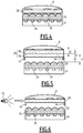
- the face 28A of the first strip is located opposite the matrix 24 of photosensors 26; the sample 4 comprising cells 5, preferably adhered 22 to the face 28A of the first coverslip, is therefore placed between the first coverslip 28 and the array 32 of microlenses 34.
- This embodiment makes it possible to dispense with the thickness of the first lamella 28 in the adjustment of the distance between the objects to be imaged and the top of the microlenses.
- This configuration has the advantage of obtaining very small, almost zero distances between the objects 22 and the microlenses 34, and of producing images as close as possible to the photosensors 26.
- the first lamella 28 is placed on the top of the microlenses 34.
- the distance H between the top of the microlenses and the face 28B facing the microlenses of the first lamella 28 is then zero.
- the adjustment of the distance between the sample support face 28A and the top of the microlenses amounts to choosing a thickness E of the first lamella 28, adapted so that the distance measured, along the optical axis Z photosensors 26, between the support face of the sample 28A and the top of the microlenses 34, ie substantially between 0 and 1500 ⁇ m, and preferably between 100 and 500 ⁇ m.
- the first medium 36 is always present in the interstices between the microlenses 34 and the first lamella 28, and consequently always acts on the acceptance cones of the photosensors 26.
- the first blade 28 comprises a blade 45, of thickness E1, and a removable blade 46, of thickness E2, contiguous to the blade 45 and defining the support face of the sample; the sum of the thicknesses E1 and E2 is consequently equal to the thickness E of the first lamella 28.
- This variant also facilitates the withdrawal of the sample without modifying the distance H between the first lamella 28 and the top of the microlenses 34 previously adjusted .
- the presence of the second coverslip 40 is above all necessary in the case of use in fluorescence, for example for imaging fluorophores or “ quantum dots ”.
- the first and second blades 28, 40 are preferably optical filters.
- the light source 18, then the excitation source is monochromatic.
- the second filter 40 is not necessary if the excitation wavelength is filtered by the first filter 28.
- the absorbance of the glass in the ultraviolet (UV) filters the excitation light if it is in the UV.
- a second example consists of a first strip 28, the face 28A or the face 28B of which is covered with a filter stack, produced by stacking dielectric layers, which absorbs the excitation wavelength.
- the optical system 17 of the imaging system 6 comprises a filter, or an array of dedicated filters, located between the array 24 of photosensors 26 and the array 32 of microlenses 34.
- this filter, or array of microlenses 34. filters is integrated into the separator element 37.
- the filters can be different under adjacent microlenses in order to characterize the same sample 4 according to at least two different wavelengths.
- the second blade 40 is a directional filter in order to compensate for the absence of a collimation system for the light source 18 which causes distortions in the image.
- the light source 18 is arranged so as to pass the light in the first coverslip 28 perpendicular to the optical axis Z so as to illuminate the sample 4 or the objects 22 from inside the coverslip.
- either one of the blades 28, 40 is a polarizer, or the two blades 28, 40 are crossed polarizers.
- the light source 18 emits rectilinearly polarized light.
- the light source 18 is a liquid crystal display (LCD).
- the second case the light source 18 does not emit polarized excitation light, and the excitation light is then polarized by the second polarizer 40.
- the excitation light is stopped by the first. polarizer 28 while the fluorescent emission light coming from sample 4 is polarized and transmitted by the first polarizer 28.
- the second polarizer 40 is in direct contact with the liquid comprising the second medium 42 to avoid depolarization of the excitation light at the air / liquid interface.
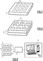
- the first coverslip 28 comprises a plurality of micro-chambers (or wells) 48 communicating or not communicating with each other.
- the micro-chambers 48 are preferably arranged in a matrix, for example the micro-chambers 48 are formed on or etched in the first lamella 28.
- the thickness E intervening in the adjustment of the distance between the face 28A of the first lamella 28 and the top of the microlenses 34 is then the distance measured along the optical axis Z between the bottom of the microchambers 48 and the face 28B of the first lamella 28.
- the microchambers 48 are formed in the entirety of the thickness E2 of the removable blade 46 previously described, and the thickness involved in the adjustment of the distance H between the face 28B of the first blade 28 and the top of the microlenses 34 is then the thickness E1 of the blade 45.
- the plurality of micro-chambers 48 form a plurality of flow zones or microchannels of the sample, intended to circulate a fluid, for example sample 4, by means of fluid actuation means integrated into the system.
- the actuating means are micropumps, microvalves, etc ...
- the plurality of micro-chambers 48 or microchannels is used, for example to carry out screening by parallelizing the observations on the same optical system 17 of the imaging system 6.
- the observations in parallel make it possible to reproduce the experiments, to study several cell types and / or several cell densities, to vary the spatial organization, the concentrations of reagents, the culture conditions, etc.
- optical signal originating from each microchamber 48 or microchannel is then recorded in order to reconstruct the image of each microchamber 48 or microchannel.
- each micro-chamber 48 or microchannel correspond to the entire lower surface of each well or study area 48, unlike the observations made by transmission in conventional optical microscopy.
- the device then comprises a plurality of imaging systems 6 controlled in parallel by the same electronic controller 8.
- the computer system 10 manages the signals from each imaging system 6 synchronously or alternately.
- the device comprises a plurality of imaging systems 6 controlled in parallel by several electronic controllers 8.
- the use of a limited number of electronic controllers 8 makes it possible to centralize the interface function between the imaging systems. according to the invention and the computer system 10.
- the imaging systems 6 are mounted on the same electronic circuit 8 and / or assembled in a housing or on a rack, in order to simplify handling by the operator and limit the space taken up by the device 2 in the rack. incubator 14.
- the first coverslip 28 is respectively the bottom of a well plate or the wall of a flask intended for cell culture.
- the walls of the well plates (or microplates) and of the flasks for cell culture are sterile and have a surface treatment which promotes cell adhesion, for example a deposit of proteins from the extracellular matrix or an oxygen plasma.
- Sterility and surface treatment improve the attachment, spreading and growth of cells on these supports, particularly on the support surface 28A of objects 5, preferably adhered cells 22.
- the figure 10 illustrates the embodiment of a device for characterizing and detecting a sample according to the invention in which the first coverslip 28 is the bottom of a well plate or microplate 50.
- the microplate 50 comprises a base 52, a support 54 comprising a plurality of wells 56 and a cover 58.
- the cover is placed on the support 54, itself placed on the base 52.
- the cover prevents evaporation of the sample. 4, in particular the cell culture medium.
- the support 54 of the microplate 50 comprises a lower extension 68.
- the total height of the support 54, with the lower extension 68, is greater than the height of a well 56.
- the lower extension 68 makes it possible to raise, for example. at least 1 mm, the bottom 60 of the wells 56 in relation to the base 52 of the microplate. This space available between the bottom 60 of the wells 56 and the base 52 is intended for the imaging system 6 and for the electronic controller 8.
- the four outer corners of the lower extension 68 of the holder 54 of the microplate 50 are rounded with a radius of curvature of 3.18 ⁇ 1.6 mm so that microplate handling robots 50 can grip the microplate 50 by them. corners.
- the device further comprises a plurality of imaging system 6 according to the invention in order to carry out studies in parallel of the samples contained in the different wells 56.
- the first coverslip 28 of each imaging system 6 is common to all the imaging systems placed under the support 54 of the microplate.
- the bottoms 60 are preferably flat and transparent to light radiation. transmitted by objects 5 of sample 4.
- the first coverslip 28 is made of glass or plastic and glued under the wells 56 by a biocompatible glue, such as a USP class 6 glue used in biomedical devices, in order to form the bottom 60 of the wells 56.
- a biocompatible glue such as a USP class 6 glue used in biomedical devices
- Metrology marks are deposited or engraved on the first slide 28 constituting the bottom 60 of the wells 56, preferably on the lower face 28B facing the microlenses.
- the metrology marks are preferably 30 ⁇ m crosses with a line thickness of 4 ⁇ m, spaced every millimeter. These marks appear on the images produced.
- the metrology marks provide a reference scale for measuring the size of cells and facilitate the cropping of images during image processing operations using the computer system 10.
- the walls of the microplate 50 (base 52, support 54, walls of the wells 56 and cover 58) other than the bottom of the wells are made of polystyrene or polypropylene.
- microplate 50 and the imaging systems 6 assembled under the microplate 50 are placed in a dark room to avoid external light disturbances.
- all or part of these walls are opaque black or white.
- the microplates whose walls are opaque and white are used more particularly for luminescence experiments.
- the walls of the microplates 50 are opaque and black in color in order to avoid external light disturbances, with the exception of the first lamella 28.
- This first lamella 28 is transparent to the light radiation transmitted by the objects 5 of the sample, for example glass or plastic.
- microplate 50 When the walls are opaque and black in color, it is not necessary to place the microplate 50 covered with its cover in a dark chamber for imaging objects 5. In fact, the walls of the microplate 50 with the cover 58 act as a darkroom. Such microplates 50 are particularly suitable for fluorescence experiments.
- the light source (s) 18 are fixed on the cover 58 facing the samples contained in the wells 56 of the microplate 50.
- each imaging system 6 comprises a light source 18 which is therefore associated with a single well in order to illuminate the sample inside it.
- the light source 18 is an electroluminescent sheet or a flat LED such as an XLamp marketed by Cree (Durham, USA).
- the light source (s) 18 can also be placed on the exterior face if the cover is transparent, or if it is opaque and black with transparent windows above each well 56, so as to illuminate the interior of each well. 56.
- light sources 18 emitting little heat are selected to limit heating and evaporation of sample 4.
- a matrix 24 of photosensors 26 surmounted by a matrix 30 of optical elements is positioned under each well 56 of a microplate 50 in order to visualize the objects 5 placed on the bottom 60 of each well 56 of the microplate 50, in particular in order to be able to produce an image of the sample 4, preferably cellular, in each well 56.
- the thickness E is then l 'thickness of the first strip 28, as in the embodiment shown in figure 4 .
- Each imaging system 6 is assembled on an electronic card 62 or printed circuit making it possible to provide the interface between the imaging systems and the electronic controller (s) 8 of the device.
- the electronic card 62 is common to a plurality of imaging systems and to one or a plurality of electronic controllers 8.
- the imaging systems are connected to a single electronic controller 8 by the electronic card 62, in order to centralize the interface function between the imaging systems according to the invention and the computer system 10.
- the electrical tracks connecting the various electronic components of the electronic card 62 are preferably buried in the printed circuit or covered with a protective varnish in order to protect them from the humid atmosphere.
- the electronic card 62 is connected to the computer system 10 via an electronic port 64, connected to the card 62, and a cable 66, connected to the port on the one hand and to the computer system 10 on the other hand.
- An opening 70 is drilled in the lower extension 68 of the microplate 50 for the passage of the cable 66 connecting the connection port 64 and the computer system 10.
- the imaging systems 6 are connected to one face of the electronic card 62 facing the wells, the port 64 and the electronic controller 8 being on the opposite face.
- each imaging system 6 is connected / assembled on an electronic daughter card connected by a connector to a mother electronic card on which the electronic controller 8 and the connection port 64 are assembled.
- the electronic card (s) 62 are integral with the microplate 50 by means of mechanical fasteners and support points arranged between the microplate 50 and the electronic card (s) 62.
- connection port 64 is a USB2, FireWire, Gigabit Ethernet or CamLink port.
- the bidirectional communications between the computer system 10 and the electronic card 62 are carried out by transmitters and receivers, and the supply of the imaging system (s) 6 is carried out by a cell or a battery near the device. device.
- the dimensions of the array 24 of photosensors 26 make it possible to cover all or only part of the bottom 60 of the well 56 opposite which it is placed.
- the dimensions of the array 30 of optical elements are substantially identical to those of the array 24 of photosensors 26 opposite which it is placed.
- each array 24 of photosensors 26 has an area of 3.6mm x 2.7mm, placed under a circular well 9mm in diameter.
- the array 24 of photodetectors 26 has an area of 6.4mm x 4.6mm placed under an 18mm diameter well.
- an array 24 of photosensors 26 and an array 30 of optical elements of dimensions less than the diameter of the well makes it possible to avoid imaging the cells located on the edge of the well, the behavior of which is often considered to be not representative of the cell population.
- the dimensions of the microplate 50 meet the main ANSI / SBS 1-2004 to 4-2004 specifications recommended by the Society for Biomolecular Screening (SBS for “ Society for Biomolecular Screening ”). More specifically, the microplates have a length of 127.76 ⁇ 0.5mm and a width of 85.48 ⁇ 0.5mm.
- Microplates 50 have an array of 2 x 3, 3 x 4, 4 x 6, 6 x 8, 8 x 12, 16 x 24 or 32 x 48 well.
- the total height of the support 54 of the microplate 50 equipped with the imaging systems 6 is between 14.35 mm and 35.00 mm, that is to say the distance, measured along the optical axis Z of the photosensors 26 , between the end of the wells 56 opposite the end in contact with the first strip 28 and the end of the extension 68 in contact with the base 52.
- the first lamella 28 is for example a glass plate 175 ⁇ m or 210 ⁇ m thick or a transparent polystyrene film 125 ⁇ m thick.
- the 50 microplates integrated with the imaging systems can be used, among others, for studies of cell proliferation, toxicology, morphological analyzes, motility, chemotaxis, viral infection, oncology, pharmaceutical or research screens. molecules influencing cellular behavior.
- the electronic card 62 has a length of 115 mm and a width of 75 mm so as to fit inside the lower extension 68 of the support 54 of the microplate 50. Thus, no component of the electronic card touches the base. 52 of the microplate 50. In addition, this base 52 protects the electronic card 62 from humidity in the incubator 14.
- Imaging systems according to the invention can also be placed against the external wall of one or more vials in order to characterize the objects placed on the internal wall of the vial or of several vials.
- the thickness E is then the thickness of the wall of the bottle.
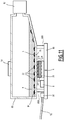
- a cell culture flask 80 is equipped with an imaging system 6 according to the invention in order to follow the proliferation of the cells in the culture flask.
- the culture flask 80 is a bottle with flat polystyrene or polypropylene walls which preferably have a surface treatment promoting cell adhesion.
- the imaging system 6 is placed under the culture flask 80 so as to image the objects, preferably cells 22 adhered to the lower wall 84 of the flask 80, the lower wall 84 being the wall facing the. imaging system 6. It forms the first lamella 28 of the imaging system 6.
- the lower wall 84 or only a part has a thickness E suitable for carrying out cell imaging according to the invention.
- the culture flask is made of polystyrene, with the exception of all or part of the lower wall 84 which is a coverslip or a glass or plastic plate of thickness E. Said coverslip, or glass or plastic plate, is glued to the polystyrene walls of the culture flask using a biocompatible glue such as USP class 6 glue.
- the imaging system 6 is connected to the electronic controller 8 via an electronic card 86.
- An electronic port 90 connected to a cable 92 is assembled to the electronic card 86 in order to connect the electronic controller 8 to the computer system. 10 of the operative part.
- the electronic card 86 is integral with the lower wall 84 of the bottle 80 by means of means 88A, 88B of mechanical fasteners and of support points arranged between the lower wall and the electronic card.
- the light source 18 is fixed on the upper wall of the flask 80.
- the flask comprises a stopper 82 to prevent evaporation of the sample 4, for example from the cell culture medium.
- a very flat light source such as an electroluminescent sheet. is then chosen to illuminate the sample in the culture flask, which facilitates stacking of flasks and imaging systems. If another type of light source is chosen, a space for the light source is reserved above each culture flask using fixing means and support points.
- the images collected by the computer system 10 can be viewed remotely using a computer server.
- the user accessing the cell images remotely can decide whether or not to change the cell culture medium or pass the cells into a new culture flask.
- Microbeads of calibrated size can be introduced into the sample in order to measure the temperature of the medium from the images produced.
- the microbeads appear on the images and the displacement of a microbead between two successive images depends on Brownian motion, that is to say on the temperature.
- the imaging system and the associated device are intended to optically detect and characterize objects, in particular cells.
- the microlenses focus the light coming from the areas of the sample into the corresponding sensitive areas of the silicon in order to collect the maximum amount of light.
- the light intensity is integrated by each photosensor.
- the array of microlenses modifies the division (discretization) of the space produced by the array of photosensors.
- the first lamella 28 generates diffraction and interference effects which promote the visualization of low contrast objects such as cells adhered to the surface of the first lamella, in particular the outline of these objects.
- the field of view of the imaging system 6 corresponds to the dimensions of the array 24 of photosensors 26.
- the field of view is widened compared to a conventional microscope over a rectangle of several mm 2 and up to. several cm 2 of surface.
- the images obtained correspond to a magnification x4 in conventional microscopy but on a larger field of approximately 3.5 x 4.5 mm 2 compared to a conventional numerical aperture objective.
- the magnification of the images differs as a function of the distance between the face 28A, support of the sample, of the first slide 28 and the top of the microlenses 34. Indeed, if the sample 4 or the objects 22 are away from the array 24 of photosensors 26, the image of the sample or objects is spread over an increasing number of photosensors 26.
- the resolution depends on the size of the pixels, however it also depends on the focal length of the microlenses, the distance between the sample 4 or the objects 22 and the photosensor array, and the refractive index n of the medium 36.
- the device has small dimensions, preferably that of a 10 cm cube, and is easily installed in an incubator.
- the reduced dimensions of the device have the advantage of the great portability of the device, considering applications at the patient bed, such as counting blood cells, or being able to be placed directly in an incubator by adding only the presence of a computer in the cell culture room.
- the invention has been described in the context of biological applications with samples comprising cells. It applies to any field with cells, for example to visualize bacteria, yeasts, fungi, pollens, algae.
Landscapes
- Health & Medical Sciences (AREA)
- Chemical & Material Sciences (AREA)
- Physics & Mathematics (AREA)
- Life Sciences & Earth Sciences (AREA)
- Engineering & Computer Science (AREA)
- General Physics & Mathematics (AREA)
- Analytical Chemistry (AREA)
- General Health & Medical Sciences (AREA)
- Biochemistry (AREA)
- Wood Science & Technology (AREA)
- Zoology (AREA)
- Bioinformatics & Cheminformatics (AREA)
- Organic Chemistry (AREA)
- Biomedical Technology (AREA)
- Optics & Photonics (AREA)
- Pathology (AREA)
- Immunology (AREA)
- Nuclear Medicine, Radiotherapy & Molecular Imaging (AREA)
- Microbiology (AREA)
- Genetics & Genomics (AREA)
- General Engineering & Computer Science (AREA)
- Sustainable Development (AREA)
- Biotechnology (AREA)
- Clinical Laboratory Science (AREA)
- Hematology (AREA)
- Biophysics (AREA)
- Molecular Biology (AREA)
- Urology & Nephrology (AREA)
- Food Science & Technology (AREA)
- Medicinal Chemistry (AREA)
- Investigating Or Analysing Materials By Optical Means (AREA)
- Apparatus Associated With Microorganisms And Enzymes (AREA)
- Investigating, Analyzing Materials By Fluorescence Or Luminescence (AREA)
- Microscoopes, Condenser (AREA)
Claims (19)
- System zum Abbilden einer Probe (4), welches aufweist eine Matrix (24) an Photosensoren (26), eine erste Lamelle (28), welche gegenüber von der Matrix (24) an Photosensoren angeordnet ist und welche eine Fläche (28A) zum Tragen der Probe definiert, und eine Gruppe (30) von optischen Elementen, welche zwischen der Matrix (24) an Photosensoren und der ersten Lamelle (28) angeordnet ist, wobei die Gruppe (30) von optischen Elementen eine Matrix (32) an Mikrolinsen (34) aufweist, wobei eine Mikrolinse (34) oberhalb von jedem Photosensor (26) der Matrix (24) an Photosensoren angeordnet ist, und dadurch gekennzeichnet, dass- die Gruppe (30) von optischen Elementen ein optisches Medium (36) aufweist, welches zwischen der Matrix (32) an Mikrolinsen und der ersten Lamelle (28) angeordnet ist, wobei das Medium Luft, Gel oder Flüssigkeit ist und der Brechungsindex des optischen Mediums (36) im Wesentlichen zwischen 1 und dem Brechungsindex der Mikrolinsen (34) liegt,- die entlang der optischen Achse (Z) der Photosensoren (26) gemessene Entfernung zwischen der Fläche zum Tragen der Probe (28A) und dem Scheitelpunkt der Mikrolinsen (34) im Wesentlichen zwischen 100 µm und 1500 µm liegt,- das System zum Abbilden die Probe (4) aufweist, welche biologische Zellen (5) aufweist,- die mit den Mikrolinsen (34) assoziierten Photosensoren (26) angeordnet sind, damit das Bild einer biologischen Zelle (5) von mindestens zwei Photosensoren (26), welche in einer ersten Richtung benachbart sind, und zwei weiteren Fotosensoren (26), welche in einer zweiten Richtung, welche zur ersten Richtung senkrecht ist, benachbart sind, abgedeckt wird,- die Brennweite jeder Mikrolinse (34) kleiner als 25 µm ist, und- die optische Achse jeder Mikrolinse (34) im Wesentlichen mit der optischen Achse eines Photosensors (26) zusammenfällt.
- System zum Abbilden gemäß Anspruch 1, wobei die entlang der optischen Achse (Z) der Photosensoren (26) gemessene Entfernung zwischen der Fläche zum Tragen der Probe (28A) und dem Scheitelpunkt der Mikrolinsen (34) kleiner oder gleich - 150 x F x n + 400 x F ist, wobei F die in der Luft gemessene Brennweite der Mikrolinsen (34) und n der Brechungsindex des optischen Mediums (36) ist, und dadurch, dass der Brechungsindex des optischen Mediums (36) im Wesentlichen zwischen 1 und 1,64 liegt.
- System zum Abbilden gemäß Anspruch 1 oder 2, welches eine Lichtquelle (18) aufweist, welche dazu bestimmt ist, die Probe (4) zu beleuchten, wobei die Lichtquelle (18) oberhalb von der Probe angeordnet ist, um ein Bild in Transmission zu erzeugen.
- System zum Abbilden gemäß Anspruch 1 oder 2, welches eine Lichtquelle (18) aufweist, welche dazu bestimmt ist, die Probe (4) zu beleuchten, wobei die Lichtquelle (18) angeordnet ist, um in die erste Lamelle (28) des Systems zum Abbilden (6) senkrecht zur optischen Achse des Systems zum Abbilden (6) zu leuchten.
- System zum Abbilden gemäß Anspruch 3 oder 4, wobei die Lichtquelle (18) geeignet ist, um mit einer Wellenlänge zu beleuchten, welche zwischen 200 nm und 800 nm liegt.
- System zum Abbilden gemäß Anspruch 5, wobei die Lichtquelle (18) ein weißes Licht ist.
- System zum Abbilden gemäß irgendeinem der Ansprüche 1 bis 6, wobei das optische Medium (36) eine Flüssigkeit ist.
- System zum Abbilden gemäß Anspruch 7, welches eine Küvette (38) aufweist, welche die Flüssigkeit und die Probe enthält.
- System zum Abbilden gemäß irgendeinem der Ansprüche 1 bis 8, welches eine zweite Lamelle (40) aufweist, welche derart angeordnet ist, dass die Probe (4) zwischen der ersten Lamelle (28) und der zweiten Lamelle (40) angeordnet ist.
- System zum Abbilden gemäß irgendeinem der Ansprüche 1 bis 9, wobei die Fläche (28A) zum Tragen der Probe (4) der ersten Lamelle (28) gegenüber von der Matrix an Photosensoren angeordnet ist.
- System zum Abbilden gemäß irgendeinem der Ansprüche 1 bis 10, wobei die erste Lamelle (28) aufweist einen Träger (45) und eine lösbare Lamelle (46), welche mit dem besagten Träger (45) verbunden ist und die Fläche (28A) zum Tragen der Probe (4) definiert.
- System zum Abbilden gemäß irgendeinem der Ansprüche 1 bis 11, welches aufweist Mittel zum Einstellen (44) der entlang der optischen Achse (Z) der Photosensoren (26) gemessenen Entfernung zwischen der Fläche zum Tragen der Probe (28A) und dem Scheitelpunkt der Mikrolinsen (34).
- System zum Abbilden gemäß irgendeinem der Ansprüche 1 bis 12, wobei die erste Lamelle (28) eine Mehrzahl von Mikrokammern (48) oder Mikrokanälen aufweist.
- System zum Abbilden gemäß irgendeinem der Ansprüche 1 bis 13, wobei die Photosensoren (26) imstande sind, ein Licht zu detektieren, welches zwischen 200 nm und 800 nm mittels Biolumineszenz, Chemilumineszenz oder Fluoreszenz emittiert wird.
- System zum Abbilden gemäß irgendeinem der Ansprüche 1 bis 14, wobei der Öffnungsdurchmesser jeder Mikrolinse (34) im Wesentlichen zwischen 0,7 µm und 10 µm liegt.
- Vorrichtung (2) zum Charakterisieren und zum Detektieren einer Probe (4), dadurch gekennzeichnet, dass es aufweist ein System zum Abbilden (6) gemäß irgendeinem der Ansprüche 1 bis 15, eine elektronische Steuereinheit (8) und ein Computersystem (10), welches dazu bestimmt ist, das System zum Abbilden (6) zu steuern.
- Vorrichtung gemäß Anspruch 16, welche zumindest zwei Systeme zum Abbilden (6) gemäß irgendeinem der Ansprüche 1 bis 15 aufweist, welche parallel mittels der elektronischen Steuereinheit (8) gesteuert werden.
- Vorrichtung gemäß Anspruch 17, wobei die erste Lamelle (28) zumindest zwei benachbarten Systemen zum Abbilden (6) gemeinsam ist.
- Vorrichtung gemäß irgendeinem der Ansprüche 16 bis 18, welche eine Inkubationskammer (14) aufweist, in welcher das System zum Abbilden (6) und die Probe (4) angeordnet sind.
Applications Claiming Priority (2)
| Application Number | Priority Date | Filing Date | Title |
|---|---|---|---|
| FR0953631A FR2946157B1 (fr) | 2009-06-02 | 2009-06-02 | Systeme d'imagerie a microlentilles et dispositif associe pour la detection d'un echantillon. |
| PCT/FR2010/051076 WO2010139900A1 (fr) | 2009-06-02 | 2010-06-02 | Système d'imagerie à microlentilles et dispositif associé pour la détection d'un échantillon |
Publications (2)
| Publication Number | Publication Date |
|---|---|
| EP2438428A1 EP2438428A1 (de) | 2012-04-11 |
| EP2438428B1 true EP2438428B1 (de) | 2021-08-18 |
Family
ID=41531857
Family Applications (1)
| Application Number | Title | Priority Date | Filing Date |
|---|---|---|---|
| EP10734785.8A Active EP2438428B1 (de) | 2009-06-02 | 2010-06-02 | Abbildende system mit microlinsen für probenmessung |
Country Status (6)
| Country | Link |
|---|---|
| US (1) | US9256008B2 (de) |
| EP (1) | EP2438428B1 (de) |
| JP (1) | JP5843761B2 (de) |
| KR (1) | KR20120026581A (de) |
| FR (1) | FR2946157B1 (de) |
| WO (1) | WO2010139900A1 (de) |
Families Citing this family (27)
| Publication number | Priority date | Publication date | Assignee | Title |
|---|---|---|---|---|
| EP2557414B1 (de) * | 2009-12-21 | 2015-03-25 | C.R.F. Società Consortile per Azioni | Optisches Detektionssystem für Kraftfahrzeuge mit mehreren Funktionen, einschließlich Detektion des Fahrbahnzustands |
| DE102011117228A1 (de) * | 2011-10-28 | 2013-05-02 | Fraunhofer-Gesellschaft zur Förderung der angewandten Forschung e.V. | Mikroskopiesystem zur Zustandsbestimmung von Zellen |
| JP5856831B2 (ja) * | 2011-12-13 | 2016-02-10 | 浜松ホトニクス株式会社 | 光計測装置 |
| JP5789724B2 (ja) | 2011-12-16 | 2015-10-07 | リ−コール インコーポレーティッド | ルミネッセンス撮像スキャナ |
| USD721704S1 (en) * | 2013-06-06 | 2015-01-27 | Li-Cor, Inc. | Chemiluminescence compact imaging scanner lid |
| WO2015174356A1 (ja) * | 2014-05-14 | 2015-11-19 | オリンパス株式会社 | 培養観察装置 |
| JP6320870B2 (ja) * | 2014-07-31 | 2018-05-09 | 株式会社東芝 | 顕微撮影装置を用いた観察方法 |
| JP6470008B2 (ja) * | 2014-10-17 | 2019-02-13 | オリンパス株式会社 | 培養観察装置および培養観察システム |
| JP6756098B2 (ja) * | 2014-10-28 | 2020-09-16 | デクセリアルズ株式会社 | フィラー充填フィルム、枚葉フィルム、積層フィルム、貼合体、及びフィラー充填フィルムの製造方法 |
| US10119915B2 (en) | 2015-04-09 | 2018-11-06 | Visera Technologies Company Limited | Detection device for specimens |
| JP2017099377A (ja) * | 2015-11-25 | 2017-06-08 | パナソニックIpマネジメント株式会社 | 細胞培養容器、細胞撮影方法、及び細胞培養システム |
| CN105301869A (zh) * | 2015-12-04 | 2016-02-03 | 山西医科大学第一医院 | 一种细胞平板克隆形成图像采集仪 |
| FR3047077B1 (fr) | 2016-01-25 | 2020-01-10 | Commissariat A L'energie Atomique Et Aux Energies Alternatives | Procede d’observation d’un echantillon par imagerie sans lentille |
| CN106018343B (zh) * | 2016-06-15 | 2019-02-12 | 暨南大学 | 一种微透镜或微透镜阵列成像检测板 |
| DE102016008854A1 (de) * | 2016-07-25 | 2018-01-25 | Universität Duisburg-Essen | System zur gleichzeitigen videografischen oder fotografischen Erfassung von mehreren Bilder |
| US10983325B2 (en) * | 2016-12-12 | 2021-04-20 | Molecular Devices, Llc | Trans-illumination imaging with an array of light sources |
| JP2020532993A (ja) * | 2017-09-07 | 2020-11-19 | コーニング インコーポレイテッド | 光学的細胞培養監視及び検体測定システム |
| JP6462837B2 (ja) * | 2017-12-01 | 2019-01-30 | 株式会社東芝 | 顕微撮影装置を用いた観察方法 |
| JP2020008682A (ja) * | 2018-07-06 | 2020-01-16 | 株式会社Iddk | 顕微観察装置、顕微観察方法および顕微観察装置の製造方法 |
| CN109337814B (zh) * | 2018-11-07 | 2024-05-14 | 深圳大学 | 细胞孔板 |
| JP6692404B2 (ja) * | 2018-12-13 | 2020-05-13 | 株式会社東芝 | 観察システム |
| WO2021011944A2 (en) * | 2019-07-18 | 2021-01-21 | Essenlix Corporation | Imaging based homogeneous assay |
| CN112094743A (zh) * | 2020-08-21 | 2020-12-18 | 南京大学 | 一种活细胞培养和实时观测系统及方法 |
| JP7644958B2 (ja) * | 2020-12-14 | 2025-03-13 | ナノティス株式会社 | 試料中の被検出物質を検出する方法 |
| EP4137865A1 (de) * | 2021-08-18 | 2023-02-22 | Leica Microsystems CMS GmbH | Automatisiertes inkubations- und mikroskopsystem |
| CN116626000A (zh) * | 2023-05-19 | 2023-08-22 | 西安理工大学 | 基于微透镜的荧光成像装置及荧光图像采集方法 |
| DE102023122869B3 (de) * | 2023-08-25 | 2025-02-20 | Freistaat Bayern (Universität Augsburg) | Autonome mikrofluidische Zellkulturplattform |
Citations (3)
| Publication number | Priority date | Publication date | Assignee | Title |
|---|---|---|---|---|
| US20010021534A1 (en) * | 1995-03-10 | 2001-09-13 | Meso Scale Technologies, Llc | Multi-array, multi-specific electrochemiluminescence testing |
| US20080290383A1 (en) * | 2005-11-30 | 2008-11-27 | Stmicroelectronics Rousset Sas | Cmos imaging device comprising a microlens array exhibiting a high filling rate |
| WO2009056065A1 (en) * | 2007-10-25 | 2009-05-07 | Industrial Technology Research Institute | Bioassay system including optical detection apparatuses, and method for detecting biomolecules |
Family Cites Families (19)
| Publication number | Priority date | Publication date | Assignee | Title |
|---|---|---|---|---|
| JP2897027B2 (ja) * | 1988-10-27 | 1999-05-31 | スズキ株式会社 | 免疫学的凝集反応検出装置 |
| US5846708A (en) * | 1991-11-19 | 1998-12-08 | Massachusetts Institiute Of Technology | Optical and electrical methods and apparatus for molecule detection |
| JPH0850100A (ja) * | 1994-08-04 | 1996-02-20 | Sony Corp | 微小物体観察装置 |
| US5694478A (en) * | 1994-12-15 | 1997-12-02 | Minnesota Mining And Manufacturing Company | Method and apparatus for detecting and identifying microbial colonies |
| US6287871B1 (en) * | 1996-03-19 | 2001-09-11 | University Of Utah Research Foundation | System for determining analyte concentration |
| JPH11173987A (ja) * | 1997-12-12 | 1999-07-02 | Hamamatsu Photonics Kk | マイクロタイタビューア |
| FR2797053B1 (fr) * | 1999-07-13 | 2001-08-31 | Commissariat Energie Atomique | Support d'analyse a transmission de lumiere de fluorescence |
| FR2812943A1 (fr) * | 2000-12-20 | 2002-02-15 | Commissariat Energie Atomique | Dispositif d'imagerie par fluorescence |
| US20020182111A1 (en) * | 2001-06-02 | 2002-12-05 | Ilya Feygin | Method and apparatus for visible spectrum imaging |
| EP2332651A3 (de) * | 2001-10-25 | 2011-08-31 | Bar Ilan University | Interaktiver transparenter Biochip-Prozessor für einzeln adressierbare Zellen |
| WO2004034477A1 (en) * | 2002-10-11 | 2004-04-22 | Smal Camera Technologies | Optical system comprising a solid-state image sensor with microlenses and a non-telecentric taking lens |
| US7170605B2 (en) * | 2003-08-25 | 2007-01-30 | Evan Francis Cromwell | Active sensor and method for optical illumination and detection |
| US7489401B2 (en) * | 2004-03-01 | 2009-02-10 | National Institute Of Advanced Industrial Science And Technology | Device for detecting emission light of micro-object |
| JP2005245288A (ja) * | 2004-03-03 | 2005-09-15 | Olympus Corp | 培養観察方法および倒立顕微鏡 |
| JP4581498B2 (ja) * | 2004-06-15 | 2010-11-17 | カシオ計算機株式会社 | 生体高分子分析チップ |
| JP2006000052A (ja) * | 2004-06-17 | 2006-01-05 | Olympus Corp | 生体試料観察システム |
| JP4731847B2 (ja) * | 2004-07-15 | 2011-07-27 | オリンパス株式会社 | ペトリディッシュ、チャンバー装置、光学顕微鏡観察方法及び試料分析方法 |
| JP2007166982A (ja) * | 2005-12-22 | 2007-07-05 | Olympus Corp | 生体試料培養観察装置 |
| JP2008237064A (ja) * | 2007-03-26 | 2008-10-09 | Tsuru Gakuen | 細胞観察装置および細胞観察方法 |
-
2009
- 2009-06-02 FR FR0953631A patent/FR2946157B1/fr not_active Expired - Fee Related
-
2010
- 2010-06-02 US US13/376,129 patent/US9256008B2/en active Active
- 2010-06-02 JP JP2012513660A patent/JP5843761B2/ja active Active
- 2010-06-02 KR KR1020117031633A patent/KR20120026581A/ko not_active Ceased
- 2010-06-02 WO PCT/FR2010/051076 patent/WO2010139900A1/fr not_active Ceased
- 2010-06-02 EP EP10734785.8A patent/EP2438428B1/de active Active
Patent Citations (3)
| Publication number | Priority date | Publication date | Assignee | Title |
|---|---|---|---|---|
| US20010021534A1 (en) * | 1995-03-10 | 2001-09-13 | Meso Scale Technologies, Llc | Multi-array, multi-specific electrochemiluminescence testing |
| US20080290383A1 (en) * | 2005-11-30 | 2008-11-27 | Stmicroelectronics Rousset Sas | Cmos imaging device comprising a microlens array exhibiting a high filling rate |
| WO2009056065A1 (en) * | 2007-10-25 | 2009-05-07 | Industrial Technology Research Institute | Bioassay system including optical detection apparatuses, and method for detecting biomolecules |
Non-Patent Citations (1)
| Title |
|---|
| CHUMIN ZHAO ET AL: "Large area CMOS active pixel sensor x-ray imager for digital breast tomosynthesis: Analysis, modeling, and characterization", MEDICAL PHYSICS, 1 November 2008 (2008-11-01), United States, pages 6294 - 6308, XP055561856, Retrieved from the Internet <URL:http://ericfossum.com/Presentations/2008%20Jan%20CMOS%20Image%20Sensors%20Past%20Present%20and%20Future.pdf> [retrieved on 20190226], DOI: 10.1118/1.4932368 * |
Also Published As
| Publication number | Publication date |
|---|---|
| JP2012529025A (ja) | 2012-11-15 |
| JP5843761B2 (ja) | 2016-01-13 |
| FR2946157A1 (fr) | 2010-12-03 |
| FR2946157B1 (fr) | 2015-03-27 |
| KR20120026581A (ko) | 2012-03-19 |
| WO2010139900A1 (fr) | 2010-12-09 |
| EP2438428A1 (de) | 2012-04-11 |
| US9256008B2 (en) | 2016-02-09 |
| US20120142086A1 (en) | 2012-06-07 |
Similar Documents
| Publication | Publication Date | Title |
|---|---|---|
| WO2010139900A1 (fr) | Système d'imagerie à microlentilles et dispositif associé pour la détection d'un échantillon | |
| AU2010286499B2 (en) | Compact automated cell counter | |
| CN104797925B (zh) | 用于不需要光学透镜而光学分析样品的容器及系统 | |
| US9995623B2 (en) | Ambient light assisted spectroscopy | |
| US20190323944A1 (en) | Image forming cytometer | |
| CA2778725C (en) | Microscopy imaging | |
| JP6513802B2 (ja) | ナノ粒子検出のためのレーザー光結合 | |
| CN102803930B (zh) | 具有聚焦光学器件的光生物传感器 | |
| US20160265974A1 (en) | Glass waveguide spectrophotometer | |
| JP2009204616A5 (de) | ||
| WO2010063936A9 (fr) | Procede et dispositif de cytometrie en flux sans fluide de gainage | |
| CN107430263B (zh) | 具有平均照明路径和平均收集路径的共焦检查系统 | |
| FR2993988A1 (fr) | Dispositif et procede de caracterisation d'un echantillon par des mesures localisees | |
| US20100182606A1 (en) | Apparatus and method for multi-parameter optical measurements | |
| CN108449968A (zh) | 手持野外便携式表面等离子体共振装置及其在化学和生物试剂的检测中的应用 | |
| CN102928419A (zh) | 荧光传感器 | |
| WO2020157265A1 (fr) | Dispositifs d'analyse de front d'onde et systemes d'imagerie microscopique comprenant de tels dispositifs d'analyse | |
| FR3051251A1 (fr) | Systeme d'observation d'une plaque a puits | |
| US20050103973A1 (en) | Fluorescence observation apparatus | |
| WO2021009465A1 (fr) | Dispositif d'observation d'une cellule ou d'un ensemble de cellules vivantes | |
| WO2010106289A1 (fr) | Dispositif de microscopie de fluorescence et methode d'observation associee | |
| WO2019141951A1 (fr) | Dispositif d'observation d'une cellule ou d'un ensemble de cellules vivantes | |
| CN102660456A (zh) | 无透镜阴影成像血细胞检测计数的装置及方法 | |
| FR2889081A1 (fr) | Dispositif microfluidique pour mesure de fluorescence et procede de mesure mettant en oeuvre un tel dispositif |
Legal Events
| Date | Code | Title | Description |
|---|---|---|---|
| PUAI | Public reference made under article 153(3) epc to a published international application that has entered the european phase |
Free format text: ORIGINAL CODE: 0009012 |
|
| 17P | Request for examination filed |
Effective date: 20111201 |
|
| AK | Designated contracting states |
Kind code of ref document: A1 Designated state(s): AL AT BE BG CH CY CZ DE DK EE ES FI FR GB GR HR HU IE IS IT LI LT LU LV MC MK MT NL NO PL PT RO SE SI SK SM TR |
|
| DAX | Request for extension of the european patent (deleted) | ||
| 17Q | First examination report despatched |
Effective date: 20150921 |
|
| STAA | Information on the status of an ep patent application or granted ep patent |
Free format text: STATUS: EXAMINATION IS IN PROGRESS |
|
| GRAP | Despatch of communication of intention to grant a patent |
Free format text: ORIGINAL CODE: EPIDOSNIGR1 |
|
| STAA | Information on the status of an ep patent application or granted ep patent |
Free format text: STATUS: GRANT OF PATENT IS INTENDED |
|
| INTG | Intention to grant announced |
Effective date: 20210329 |
|
| GRAS | Grant fee paid |
Free format text: ORIGINAL CODE: EPIDOSNIGR3 |
|
| GRAA | (expected) grant |
Free format text: ORIGINAL CODE: 0009210 |
|
| STAA | Information on the status of an ep patent application or granted ep patent |
Free format text: STATUS: THE PATENT HAS BEEN GRANTED |
|
| AK | Designated contracting states |
Kind code of ref document: B1 Designated state(s): AL AT BE BG CH CY CZ DE DK EE ES FI FR GB GR HR HU IE IS IT LI LT LU LV MC MK MT NL NO PL PT RO SE SI SK SM TR |
|
| REG | Reference to a national code |
Ref country code: GB Ref legal event code: FG4D Free format text: NOT ENGLISH |
|
| REG | Reference to a national code |
Ref country code: CH Ref legal event code: EP |
|
| REG | Reference to a national code |
Ref country code: DE Ref legal event code: R096 Ref document number: 602010067452 Country of ref document: DE |
|
| REG | Reference to a national code |
Ref country code: IE Ref legal event code: FG4D Free format text: LANGUAGE OF EP DOCUMENT: FRENCH Ref country code: AT Ref legal event code: REF Ref document number: 1422080 Country of ref document: AT Kind code of ref document: T Effective date: 20210915 |
|
| REG | Reference to a national code |
Ref country code: LT Ref legal event code: MG9D |
|
| REG | Reference to a national code |
Ref country code: NL Ref legal event code: MP Effective date: 20210818 |
|
| REG | Reference to a national code |
Ref country code: AT Ref legal event code: MK05 Ref document number: 1422080 Country of ref document: AT Kind code of ref document: T Effective date: 20210818 |
|
| PG25 | Lapsed in a contracting state [announced via postgrant information from national office to epo] |
Ref country code: SE Free format text: LAPSE BECAUSE OF FAILURE TO SUBMIT A TRANSLATION OF THE DESCRIPTION OR TO PAY THE FEE WITHIN THE PRESCRIBED TIME-LIMIT Effective date: 20210818 Ref country code: HR Free format text: LAPSE BECAUSE OF FAILURE TO SUBMIT A TRANSLATION OF THE DESCRIPTION OR TO PAY THE FEE WITHIN THE PRESCRIBED TIME-LIMIT Effective date: 20210818 Ref country code: PT Free format text: LAPSE BECAUSE OF FAILURE TO SUBMIT A TRANSLATION OF THE DESCRIPTION OR TO PAY THE FEE WITHIN THE PRESCRIBED TIME-LIMIT Effective date: 20211220 Ref country code: NO Free format text: LAPSE BECAUSE OF FAILURE TO SUBMIT A TRANSLATION OF THE DESCRIPTION OR TO PAY THE FEE WITHIN THE PRESCRIBED TIME-LIMIT Effective date: 20211118 Ref country code: FI Free format text: LAPSE BECAUSE OF FAILURE TO SUBMIT A TRANSLATION OF THE DESCRIPTION OR TO PAY THE FEE WITHIN THE PRESCRIBED TIME-LIMIT Effective date: 20210818 Ref country code: ES Free format text: LAPSE BECAUSE OF FAILURE TO SUBMIT A TRANSLATION OF THE DESCRIPTION OR TO PAY THE FEE WITHIN THE PRESCRIBED TIME-LIMIT Effective date: 20210818 Ref country code: LT Free format text: LAPSE BECAUSE OF FAILURE TO SUBMIT A TRANSLATION OF THE DESCRIPTION OR TO PAY THE FEE WITHIN THE PRESCRIBED TIME-LIMIT Effective date: 20210818 Ref country code: BG Free format text: LAPSE BECAUSE OF FAILURE TO SUBMIT A TRANSLATION OF THE DESCRIPTION OR TO PAY THE FEE WITHIN THE PRESCRIBED TIME-LIMIT Effective date: 20211118 Ref country code: AT Free format text: LAPSE BECAUSE OF FAILURE TO SUBMIT A TRANSLATION OF THE DESCRIPTION OR TO PAY THE FEE WITHIN THE PRESCRIBED TIME-LIMIT Effective date: 20210818 |
|
| PG25 | Lapsed in a contracting state [announced via postgrant information from national office to epo] |
Ref country code: PL Free format text: LAPSE BECAUSE OF FAILURE TO SUBMIT A TRANSLATION OF THE DESCRIPTION OR TO PAY THE FEE WITHIN THE PRESCRIBED TIME-LIMIT Effective date: 20210818 Ref country code: LV Free format text: LAPSE BECAUSE OF FAILURE TO SUBMIT A TRANSLATION OF THE DESCRIPTION OR TO PAY THE FEE WITHIN THE PRESCRIBED TIME-LIMIT Effective date: 20210818 Ref country code: GR Free format text: LAPSE BECAUSE OF FAILURE TO SUBMIT A TRANSLATION OF THE DESCRIPTION OR TO PAY THE FEE WITHIN THE PRESCRIBED TIME-LIMIT Effective date: 20211119 |
|
| PG25 | Lapsed in a contracting state [announced via postgrant information from national office to epo] |
Ref country code: NL Free format text: LAPSE BECAUSE OF FAILURE TO SUBMIT A TRANSLATION OF THE DESCRIPTION OR TO PAY THE FEE WITHIN THE PRESCRIBED TIME-LIMIT Effective date: 20210818 |
|
| PG25 | Lapsed in a contracting state [announced via postgrant information from national office to epo] |
Ref country code: DK Free format text: LAPSE BECAUSE OF FAILURE TO SUBMIT A TRANSLATION OF THE DESCRIPTION OR TO PAY THE FEE WITHIN THE PRESCRIBED TIME-LIMIT Effective date: 20210818 |
|
| REG | Reference to a national code |
Ref country code: DE Ref legal event code: R097 Ref document number: 602010067452 Country of ref document: DE |
|
| PG25 | Lapsed in a contracting state [announced via postgrant information from national office to epo] |
Ref country code: SM Free format text: LAPSE BECAUSE OF FAILURE TO SUBMIT A TRANSLATION OF THE DESCRIPTION OR TO PAY THE FEE WITHIN THE PRESCRIBED TIME-LIMIT Effective date: 20210818 Ref country code: SK Free format text: LAPSE BECAUSE OF FAILURE TO SUBMIT A TRANSLATION OF THE DESCRIPTION OR TO PAY THE FEE WITHIN THE PRESCRIBED TIME-LIMIT Effective date: 20210818 Ref country code: RO Free format text: LAPSE BECAUSE OF FAILURE TO SUBMIT A TRANSLATION OF THE DESCRIPTION OR TO PAY THE FEE WITHIN THE PRESCRIBED TIME-LIMIT Effective date: 20210818 Ref country code: EE Free format text: LAPSE BECAUSE OF FAILURE TO SUBMIT A TRANSLATION OF THE DESCRIPTION OR TO PAY THE FEE WITHIN THE PRESCRIBED TIME-LIMIT Effective date: 20210818 Ref country code: CZ Free format text: LAPSE BECAUSE OF FAILURE TO SUBMIT A TRANSLATION OF THE DESCRIPTION OR TO PAY THE FEE WITHIN THE PRESCRIBED TIME-LIMIT Effective date: 20210818 Ref country code: AL Free format text: LAPSE BECAUSE OF FAILURE TO SUBMIT A TRANSLATION OF THE DESCRIPTION OR TO PAY THE FEE WITHIN THE PRESCRIBED TIME-LIMIT Effective date: 20210818 |
|
| PLBE | No opposition filed within time limit |
Free format text: ORIGINAL CODE: 0009261 |
|
| STAA | Information on the status of an ep patent application or granted ep patent |
Free format text: STATUS: NO OPPOSITION FILED WITHIN TIME LIMIT |
|
| 26N | No opposition filed |
Effective date: 20220519 |
|
| PG25 | Lapsed in a contracting state [announced via postgrant information from national office to epo] |
Ref country code: IT Free format text: LAPSE BECAUSE OF FAILURE TO SUBMIT A TRANSLATION OF THE DESCRIPTION OR TO PAY THE FEE WITHIN THE PRESCRIBED TIME-LIMIT Effective date: 20210818 |
|
| PG25 | Lapsed in a contracting state [announced via postgrant information from national office to epo] |
Ref country code: SI Free format text: LAPSE BECAUSE OF FAILURE TO SUBMIT A TRANSLATION OF THE DESCRIPTION OR TO PAY THE FEE WITHIN THE PRESCRIBED TIME-LIMIT Effective date: 20210818 |
|
| PG25 | Lapsed in a contracting state [announced via postgrant information from national office to epo] |
Ref country code: MC Free format text: LAPSE BECAUSE OF FAILURE TO SUBMIT A TRANSLATION OF THE DESCRIPTION OR TO PAY THE FEE WITHIN THE PRESCRIBED TIME-LIMIT Effective date: 20210818 |
|
| GBPC | Gb: european patent ceased through non-payment of renewal fee |
Effective date: 20220602 |
|
| PG25 | Lapsed in a contracting state [announced via postgrant information from national office to epo] |
Ref country code: LU Free format text: LAPSE BECAUSE OF NON-PAYMENT OF DUE FEES Effective date: 20220602 Ref country code: IE Free format text: LAPSE BECAUSE OF NON-PAYMENT OF DUE FEES Effective date: 20220602 |
|
| PG25 | Lapsed in a contracting state [announced via postgrant information from national office to epo] |
Ref country code: GB Free format text: LAPSE BECAUSE OF NON-PAYMENT OF DUE FEES Effective date: 20220602 |
|
| PG25 | Lapsed in a contracting state [announced via postgrant information from national office to epo] |
Ref country code: HU Free format text: LAPSE BECAUSE OF FAILURE TO SUBMIT A TRANSLATION OF THE DESCRIPTION OR TO PAY THE FEE WITHIN THE PRESCRIBED TIME-LIMIT; INVALID AB INITIO Effective date: 20100602 |
|
| PG25 | Lapsed in a contracting state [announced via postgrant information from national office to epo] |
Ref country code: MK Free format text: LAPSE BECAUSE OF FAILURE TO SUBMIT A TRANSLATION OF THE DESCRIPTION OR TO PAY THE FEE WITHIN THE PRESCRIBED TIME-LIMIT Effective date: 20210818 Ref country code: CY Free format text: LAPSE BECAUSE OF FAILURE TO SUBMIT A TRANSLATION OF THE DESCRIPTION OR TO PAY THE FEE WITHIN THE PRESCRIBED TIME-LIMIT Effective date: 20210818 |
|
| PG25 | Lapsed in a contracting state [announced via postgrant information from national office to epo] |
Ref country code: TR Free format text: LAPSE BECAUSE OF FAILURE TO SUBMIT A TRANSLATION OF THE DESCRIPTION OR TO PAY THE FEE WITHIN THE PRESCRIBED TIME-LIMIT Effective date: 20210818 |
|
| PG25 | Lapsed in a contracting state [announced via postgrant information from national office to epo] |
Ref country code: MT Free format text: LAPSE BECAUSE OF FAILURE TO SUBMIT A TRANSLATION OF THE DESCRIPTION OR TO PAY THE FEE WITHIN THE PRESCRIBED TIME-LIMIT Effective date: 20210818 |
|
| PGFP | Annual fee paid to national office [announced via postgrant information from national office to epo] |
Ref country code: DE Payment date: 20250618 Year of fee payment: 16 |
|
| PGFP | Annual fee paid to national office [announced via postgrant information from national office to epo] |
Ref country code: BE Payment date: 20250624 Year of fee payment: 16 |
|
| PGFP | Annual fee paid to national office [announced via postgrant information from national office to epo] |
Ref country code: FR Payment date: 20250623 Year of fee payment: 16 |
|
| PGFP | Annual fee paid to national office [announced via postgrant information from national office to epo] |
Ref country code: CH Payment date: 20250701 Year of fee payment: 16 |
|
| REG | Reference to a national code |
Ref country code: CH Ref legal event code: R18 Free format text: ST27 STATUS EVENT CODE: U-0-0-R10-R18 (AS PROVIDED BY THE NATIONAL OFFICE) Effective date: 20260106 |