EP2437634B1 - Sitzmöbel - Google Patents
Sitzmöbel Download PDFInfo
- Publication number
- EP2437634B1 EP2437634B1 EP11743823.4A EP11743823A EP2437634B1 EP 2437634 B1 EP2437634 B1 EP 2437634B1 EP 11743823 A EP11743823 A EP 11743823A EP 2437634 B1 EP2437634 B1 EP 2437634B1
- Authority
- EP
- European Patent Office
- Prior art keywords
- frame
- seating surface
- seat
- seat according
- frame upper
- Prior art date
- Legal status (The legal status is an assumption and is not a legal conclusion. Google has not performed a legal analysis and makes no representation as to the accuracy of the status listed.)
- Active
Links
Images


Classifications
-
- A—HUMAN NECESSITIES
- A47—FURNITURE; DOMESTIC ARTICLES OR APPLIANCES; COFFEE MILLS; SPICE MILLS; SUCTION CLEANERS IN GENERAL
- A47C—CHAIRS; SOFAS; BEDS
- A47C3/00—Chairs characterised by structural features; Chairs or stools with rotatable or vertically-adjustable seats
- A47C3/14—Chairs characterised by structural features; Chairs or stools with rotatable or vertically-adjustable seats of asymmetrical shape
-
- A—HUMAN NECESSITIES
- A47—FURNITURE; DOMESTIC ARTICLES OR APPLIANCES; COFFEE MILLS; SPICE MILLS; SUCTION CLEANERS IN GENERAL
- A47C—CHAIRS; SOFAS; BEDS
- A47C3/00—Chairs characterised by structural features; Chairs or stools with rotatable or vertically-adjustable seats
- A47C3/02—Rocking chairs
- A47C3/021—Rocking chairs having elastic frames
- A47C3/023—Rocking chairs having elastic frames made of tubular material
-
- A—HUMAN NECESSITIES
- A47—FURNITURE; DOMESTIC ARTICLES OR APPLIANCES; COFFEE MILLS; SPICE MILLS; SUCTION CLEANERS IN GENERAL
- A47C—CHAIRS; SOFAS; BEDS
- A47C3/00—Chairs characterised by structural features; Chairs or stools with rotatable or vertically-adjustable seats
- A47C3/04—Stackable chairs or nesting chairs
-
- A—HUMAN NECESSITIES
- A47—FURNITURE; DOMESTIC ARTICLES OR APPLIANCES; COFFEE MILLS; SPICE MILLS; SUCTION CLEANERS IN GENERAL
- A47C—CHAIRS; SOFAS; BEDS
- A47C3/00—Chairs characterised by structural features; Chairs or stools with rotatable or vertically-adjustable seats
- A47C3/12—Chairs characterised by structural features; Chairs or stools with rotatable or vertically-adjustable seats with shell-shaped seat and back-rest unit, e.g. having arm-rests
-
- A—HUMAN NECESSITIES
- A47—FURNITURE; DOMESTIC ARTICLES OR APPLIANCES; COFFEE MILLS; SPICE MILLS; SUCTION CLEANERS IN GENERAL
- A47C—CHAIRS; SOFAS; BEDS
- A47C5/00—Chairs of special materials
- A47C5/04—Metal chairs, e.g. tubular
-
- A—HUMAN NECESSITIES
- A47—FURNITURE; DOMESTIC ARTICLES OR APPLIANCES; COFFEE MILLS; SPICE MILLS; SUCTION CLEANERS IN GENERAL
- A47C—CHAIRS; SOFAS; BEDS
- A47C7/00—Parts, details, or accessories of chairs or stools
Definitions
- the invention relates to a chair, in particular a chair, with a resilient frame on which a seat can be arranged.
- a cantilever is a chair without hind legs, whose seat under the weight of a person yielding resiliently and sinks slightly backwards.
- a cantilever has a supporting frame, wherein the front legs forming parts of the frame in each case buckle down and back to top. At the bottom, the frame continues on the floor to the rear edge of the chair. At the top, the frame runs parallel to the parts of the frame that run along the floor to the rear edge of the chair, and the two sides of the frame are also in parallel planes. In the side view, the frame of such a cantilever on a substantially U-shape.
- the upper parts of the frame serve as a support for the seat surface, wherein the upper parts of the frame are substantially parallel to each other and wherein the seat surface is arranged substantially between the two upper parts of the frame.
- the chair has a frame top, two frame bottoms and two frame middle parts each connecting a frame bottom to the frame top.
- the frame upper part extends from a rear region of a seat surface which can be arranged on the frame upper part into a front region of the seat surface.
- the frame bases form at least partially parallel to the seat and from the front of the seat in the rear of the seat extending floor skids.
- the frame middle parts each extend from the respective frame lower part in the rear region of the seat surface obliquely upwards to the frame upper part in the front region of the seat surface.
- a chair is known with a frame that forms a floor support and has a lower part that extends from the front side upwards. At the top of the lower part, two rearwardly extending seat support join, which run parallel to each other.
- Object of the present invention was to provide a chair, in particular a chair, with a resilient frame, which avoids the known from the prior art disadvantages and in particular a offers high seating comfort and flexibility.
- a chair in particular a chair, with a resiliently shaped frame, which in the side view is substantially Z-shaped and which comprises a frame top, two frame bases and two frame middle parts each connecting a frame base to the frame top.
- the frame upper part extends from a rear region of a seat surface which can be arranged on the frame upper part into a front one Area of the seat.
- the frame bases form at least partially parallel to the seat and from the front of the seat in the rear of the seat extending floor skids.
- the frame middle parts each extend from the respective frame lower part in the rear region of the seat surface obliquely upwards to the frame upper part in the front region of the seat surface, whereby in a preferred embodiment the lateral distance between the frame middle parts and the frame upper part and thus the seat surface decreases.
- the distance of the frame center parts to each other on the frame top corresponds to a maximum of two-thirds, preferably a maximum of half the width of the seat in the front area to allow an at least partially lateral, ergonomically advantageous movement of the frame shell against the frame bases when using the chair without them the frame bases lift off the ground substantially.
- the present invention in the region of the frame shell, ie in the region of the seat, small distance between the middle parts of the frame rocking the seat is allowed to the right and to the left, which gives a particularly comfortable sitting. Because the Z-shaped configuration of the frame and a rocking forward and forward is possible, the seat can be tilted almost in any direction.
- the substantially Z-shaped configuration of the upwardly converging frame also achieves improved stackability of the seat, since the central frame parts in the stacked state are not exactly in front of each other, as in the case of free-swinging devices known in the art, but partly overlap. As a result, a certain degree of self-centering of the stacked seating furniture is achieved.
- the overlap ensures that the upper seating furniture is not offset, as in the prior art, by at least the thickness of the frame central part in two stacked seats, but only by a portion of this thickness.
- This allows more seating to be stacked on top of one another until the stack becomes unstable due to the center of gravity moving forward with increasing altitude.
- by the of the respective frame lower part in the rear area of the seat obliquely upward to the frame upper part in the front region of the seat extending frame middle parts achieved a particularly good freedom of movement in the leg and foot area.
- the distance between the middle parts of the frame on the upper frame part can correspond to a maximum of one third of the width of the seat surface in the front region.
- the frame bases may be substantially parallel to each other.
- the frame upper part can be substantially trapezoidal in shape and become wider towards the rear region of the seat so that a stable arrangement of the seat surface on the frame upper part is ensured.
- a connecting element which is inclined against the surface formed by the upper frame part.
- the connecting element may on the one hand be provided to increase the stability of the frame in the upper region, on the other hand, the connecting element may be used to connect the seat to the frame.
- the connecting element preferably has a fastening device, so that arm supports and / or writing supports can be attached to the connecting element.
- the frame may be configured in one piece.
- the frame metal preferably steel, on, wherein the frame has a round, preferably circular profile.
- the frame may also comprise a durable plastic.
- a transverse strut may be provided, which connects the frame bases together.
- the transverse strut is preferably arranged in the middle or in the rear region of the frame lower parts. This increases the stability of the frame even further.
- Fig. 1 shows a seating furniture according to the invention, here a chair, with a resilient frame 10.
- the frame 10 comprises two frame bases 12a, 12b, a frame top 11 and two each frame frame 12a, 12b with the frame top 11 connecting termemitteilmaschine 13a, 13b.
- the frame has a substantially Z-shape.
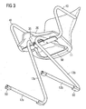
- the Z-shaped configuration of the frame in the side view is in Fig. 3 particularly easy to recognize.
- the frame center parts 13a, 13b each run from the rear, laterally outer region of the frame bases 12a, 12b obliquely upwards to the frame top 11 in the front region of the seat surface 20, where their lateral distance is less.
- the stability of the frame 10 is given despite the lack of front legs in that the force that arises from the sitting down of a person on the chair, is derived via the tension in the middle frame parts 13a, 13b obliquely backwards to the frame bases 12a, 12b.
- the frame central parts 13a, 13b converge towards the frame upper part 11, so that the distance between the frame middle parts 13a, 13b to each other in the front region of the seat surface 20 is smaller than in the rear region of the seat surface 20, ie where the middle frame parts 13a, 13b on the frame bases 12a, 12b meet.
- the convergence of the frame center parts to the frame top 11 out is special good at Fig. 4 can be seen and referred to Fig. 4 described in more detail.
- the frame top 11 is designed trapezoidal here and is wider to the rear of the seat 20. This ensures that the seat 20 can be stably arranged on the frame upper part 11.
- a transverse strut may be provided between the frame bases 12a, 12b and / or the frame middle parts 13a, 13b (not shown here).
- the transverse strut is arranged in the rear region of the frame lower parts 12a, 12b. It essentially prevents the frame bases from moving against each other when loaded.
- this may also be designed substantially rectangular or circular.
- the frame lower parts 12a, 12b run essentially parallel to the seat surface 20 and have floor protectors at the front and at the rear end, respectively.
- the two frame bases 12a, 12b can each be designed as floor skids, the floor skids in the front area and in the rear area may have an upward curvature and extend substantially straight in the central region.
- a seat with a configuration of the frame bases 12a, 12b as floor skids is used in the middle, straight area for normal sitting, while the seating furniture follows the movement of the user when it leans forward or backward.
- Armrests 40 are attached to the frame upper part 11, which are guided laterally outwards below the seat surface 20 and are guided upwards outside the seat surface 20.
- a writing pad or writing support On one of the armrests 40 may alternatively be arranged a writing pad or writing support, which is preferably designed to be pivotable.
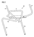
- Fig. 2 shows a frame of a chair according to the invention in an isometric view with attached to the frame armrests.
- a connecting element 30 is arranged, which is fixedly connected to the frame upper part 11.
- the connecting element 30 or a part of the connecting element 30 is inclined against the surface formed by the frame upper part 11.
- the inclined part of the connecting element 30 is provided to connect the seat surface 20, for example by means of a screw connection with the frame 10.
- the fastening device 30 may additionally be provided to increase the stability of the frame in the upper region.
- the connecting element 30 also has a fastening device, so that the armrest and / or writing supports or writing pads can be attached to the connecting element.
- a plate can be attached to the connecting element which extends substantially laterally beyond the frame top.
- an armrest 40 can be attached to the protruding parts.
- the armrests 40 can also be attached to the plate in such a way that, for example, they can be pivoted forward into the region below the seat surface.
- a locking mechanism may additionally be provided to lock the armrest 40 in use.
- Fig. 3 shows a seating according to the invention in an isometric view substantially from below.
- Clearly recognizable here is the side view substantially Z-shaped frame configured.
- the seat surface 20 has in the rear area a recess or a depression 50 into which the portion of the substantially trapezoidal frame upper part running in the rear region of the seat surface 20 can be arranged in a form-fitting manner.
- this has on the underside a stable surface 35, on which the seat 20 can be connected to the connecting element 30.
- the stable surface 35 corresponds to the inclined surface of the connecting element 30.
- the inclined surface may have a plurality of boreholes for connecting the frame to the seating surface 20 to provide a threaded connection of the connecting element 30 to the seating surface 20.
- the stable surface 35 together with the recess or recess 50 allows a particularly simple yet secure connection of the seat surface 20 with the frame 10.
- a force is applied, which in the recess or Deepening 50 arranged part of the frame upper part 11 clamped against the recess or recess 50.
- the recess 50 preferably has a recess running on the front side wall into which the frame part arranged in the recess 50 is drawn when connecting the stable surface 35 with the connecting element 30. This simultaneously prevents that the rear portion of the seat 20 can be pivoted away from the frame 11 upwards.
- the assembly of the seat is considerably simplified, since ultimately only the stable surface 35 must be connected to the connecting element 30.
- the recess 50 may also each extend laterally on the underside of the seat surface 20 into the front region of the seat surface 20, so that the side parts of the substantially trapezoidally shaped frame upper part can be arranged in the recess 50 preferably form-fitting manner. Thus, a displacement of the seat 20 in the lateral direction can be prevented.
- the stable surface 35 or the connecting element 30 can provide pins which can each latch into corresponding recesses on the connecting element 30 or on the stable surface 35.
- the seat can be connected to the frame, without the need screw or tool would be necessary.
- the seat 20 can then be suspended with its recess 50 in the rear region of the trapezoidal frame upper part 11. Subsequently, the seat surface 20 or the arranged on the underside of the seat 20 stable surface 35 can be pressed against the connecting element 30 until the pins engage in the respective recesses.
- a subsequent release of the seat 20 from the frame can be ensured by the fact that the stable surface 35 has a certain flexibility in order to release the pins from the corresponding recesses.
- Fig. 4 shows a seating furniture according to the invention in a top view from the front, wherein the seat 20 is shown only schematically.
- the distance a of the frame central parts 13a, 13b from one another in the front region of the seat surface 20 is smaller than the width A of the seat surface 20 in the front region of the seat surface 20. It is particularly advantageous if the distance a corresponds to a maximum of half the width A. It has proven to be particularly advantageous to choose the distance a between the two frame middle parts 13a, 13b in the front region of the seat surface 20 such that it is at most one third of the width A of the seat surface 20 in the front region equivalent.
- a rocking of the seat to the left and to the right is possible, which can be effected by simple weight shift to the left or to the right.
- the frame is designed in one piece in the embodiment shown here, wherein the frame metal, preferably steel, and wherein the frame has a round, preferably a circular profile.
- the frame can also be designed in several parts.
- the frame may be configured in two parts, with the right part and the left part of the frame each forming part of the two-part frame.
- the frame can also have a durable plastic.
- the frame may also have another suitable profile for this purpose.
- the arranged on the frame top seat 20 may comprise plastic or wood.
- the top of the seat 20 may also be provided with a padding.
- the armrests 40 may have a padding.
Landscapes
- Chair Legs, Seat Parts, And Backrests (AREA)
- Chairs Characterized By Structure (AREA)
- Chairs For Special Purposes, Such As Reclining Chairs (AREA)
Description
- Die Erfindung betrifft ein Sitzmöbel, insbesondere einen Stuhl, mit einem federnd ausgebildeten Rahmen, auf welchem eine Sitzfläche anordenbar ist.
- Sitzmöbel, insbesondere Stühle, mit einem federnd ausgebildeten Rahmen sind aus dem Stand der Technik als sogenannte Freischwinger bekannt. Ein Freischwinger ist ein Stuhl ohne Hinterbeine, dessen Sitzfläche unter dem Gewicht einer Person federnd nachgibt und leicht nach hinten absinkt. Ein Freischwinger weist einen tragenden Rahmen auf, wobei die die Vorderbeine bildenden Teile des Rahmens jeweils unten und oben nach hinten wegknicken. Unten verläuft der Rahmen jeweils auf dem Boden weiter bis zum hinteren Rand des Stuhls. Oben verläuft der Rahmen jeweils parallel zu den am Boden verlaufenden Teile des Rahmens bis zum hinteren Rand des Stuhls, die beiden Seiten des Rahmens liegen ebenfalls in parallelen Ebenen. In der Seitenansicht weist der Rahmen eines solchen Freischwingers im Wesentlichen eine U-Form auf. Die oberen Teile des Rahmens dienen als Träger für die Sitzfläche, wobei die oberen Teile des Rahmens im Wesentlichen parallel zueinander verlaufen und wobei die Sitzfläche im Wesentlichen zwischen den beiden oberen Teilen des Rahmens angeordnet ist.
- Aus der
AT 128771 - Aus der
US 2008/0100120 A1 ist ein Stuhl mit einem federnd ausgebildeten Rahmen bekannt. Der Stuhl weist ein Rahmenoberteil, zwei Rahmenunterteile und zwei jeweils ein Rahmenunterteil mit dem Rahmenoberteil verbindende Rahmenmittelteile auf. Das Rahmenoberteil verläuft von einem hinteren Bereich einer an das Rahmenoberteil anordenbaren Sitzfläche in einen vorderen Bereich der Sitzfläche. Die Rahmenunterteile bilden zumindest teilweise parallel zur Sitzfläche und vom vorderen Bereich der Sitzfläche in den hinteren Bereich der Sitzfläche verlaufende Bodenkufen. Die Rahmenmittelteile verlaufen jeweils von dem jeweiligen Rahmenunterteil im hinteren Bereich der Sitzfläche schräg nach oben zum Rahmenoberteil im vorderen Bereich der Sitzfläche. - Aus der
DE 93 00 705 U1 ist ein Sitzmöbel mit einem Rahmen bekannt, der eine Bodenauflage bildet und ein sich von der Vorderseite nach oben erstreckendes Unterteil aufweist. An der Oberseite des Unterteils schließen sich zwei nach hinten erstreckende Sitzträger an, die parallel zueinander verlaufen. - Die aus dem Stand der Technik bekannten Freischwinger weisen den Nachteil auf, dass die Sitzfläche zwar nach hinten federnd, ein Schwingen in seitliche Richtung aber nicht möglich ist. Ein weiterer Nachteil vor allem der Freischwinger in U-Form besteht darin, dass sie aufgrund der Ausgestaltung des Rahmens nicht ideal stapelbar sind.
- Aufgabe der vorliegenden Erfindung war es, ein Sitzmöbel, insbesondere einen Stuhl, mit einem federnd ausgebildeten Rahmen bereitzustellen, welcher die aus dem Stand der Technik bekannten Nachteile vermeidet und insbesondere einen hohen Sitzkomfort und Flexibilität bietet.
- Diese Aufgabe wird erfindungsgemäß durch ein Sitzmöbel, insbesondere einen Stuhl, mit einem federnd ausgebildeten Rahmen nach dem unabhängigen Anspruch gelöst. Vorteilhafte Ausgestaltungen der Erfindung ergeben sich aus den abhängigen Ansprüchen.
- Bereitgestellt wird demnach ein Sitzmöbel, insbesondere ein Stuhl, mit einem federnd ausgebildeten Rahmen, welcher in der Seitenansicht im Wesentlichen Z-förmig ausgestaltet ist und welcher ein Rahmenoberteil, zwei Rahmenunterteile und zwei jeweils ein Rahmenunterteil mit dem Rahmenoberteil verbindende Rahmenmittelteile umfasst. Das Rahmenoberteil verläuft von einem hinteren Bereich einer an dem Rahmenoberteil anordenbaren Sitzfläche in einen vorderen Bereich der Sitzfläche. Die Rahmenunterteile bilden zumindest teilweise parallel zur Sitzfläche und vom vorderen Bereich der Sitzfläche in den hinteren Bereich der Sitzfläche verlaufende Bodenkufen. Die Rahmenmittelteile verlaufen jeweils von dem jeweiligen Rahmenunterteil im hinteren Bereich der Sitzfläche schräg nach oben zum Rahmenoberteil im vorderen Bereich der Sitzfläche, wobei sich bei einer bevorzugten Ausführungsform der seitliche Abstand der Rahmenmittelteile zum Rahmenoberteil und damit zur Sitzfläche hin verringert. Der Abstand der Rahmenmittelteile zueinander am Rahmenoberteil entspricht maximal zwei Drittel, vorzugsweise maximal der Hälfte der Breite der Sitzfläche im vorderen Bereich, um eine zumindest teilweise seitliche, ergonomisch vorteilhafte Bewegung des Rahmenoberteils gegen die Rahmenunterteile bei Benutzung des Sitzmöbels zu ermöglichen, ohne dass sie die Rahmenunterteile wesentlich vom Boden abheben.
- Durch den erfindungsgemäß im Bereich des Rahmenoberteils, also im Bereich der Sitzfläche, geringen Abstand der Rahmenmittelteile zueinander wird ein Wippen der Sitzfläche nach rechts und nach links ermöglicht, was ein besonders angenehmes Sitzen vermittelt. Weil durch die Z-förmige Ausgestaltung des Rahmens auch ein Wippen nach hinten und nach vorne möglich ist, kann die Sitzfläche nahezu in jede Richtung gewippt werden. Durch die im Wesentlichen Z-förmige Ausgestaltung des nach oben zusammenlaufenden Rahmens wird zudem eine verbesserte Stapelbarkeit des Sitzmöbels erreicht, da die Rahmenmittelteile im gestapelten Zustand nicht genau voreinander liegen, wie bei im Stand der Technik bekannten Freischwingern, sondern zum Teil überlappen. Dadurch wird eine gewisse Selbstzentrierung der gestapelten Sitzmöbel erreicht. Gleichzeitig sorgt die Überlappung dafür, dass das obere Sitzmöbel bei zwei gestapelten Sitzmöbeln nicht, wie im Stand der Technik, um mindestens die Dicke des Rahmenmittelteils nach vorne versetzt ist, sondern nur um einen Teil dieser Dicke. Damit können mehr Sitzmöbel übereinander gestapelt werden, bis der Stapel wegen des mit steigender Höhe nach vorne wandernden Schwerpunktes instabil wird. Zusätzlich wird durch die von dem jeweiligen Rahmenunterteil im hinteren Bereich der Sitzfläche schräg nach oben zum Rahmenoberteil im vorderen Bereich der Sitzfläche verlaufenden Rahmenmittelteile eine besonders gute Bewegungsfreiheit im Bein-und Fußbereich erzielt.
- In einer Ausgestaltung des erfindungsgemäßen Sitzmöbels kann der Abstand der Rahmenmittelteile zueinander am Rahmenoberteil maximal einem Drittel der Breite der Sitzfläche im vorderen Bereich entsprechen. Damit kann ein Wippen der Sitzfläche nach links und nach rechts noch weiter verbessert werden.
- In einer Ausgestaltung der Erfindung können die Rahmenunterteile im Wesentlichen parallel zueinander verlaufen.
- Das Rahmenoberteil kann im Wesentlichen trapezförmig ausgestaltet sein und zum hinteren Bereich der Sitzfläche breiter werden, so dass eine stabile Anordnung der Sitzfläche an dem Rahmenoberteil gewährleistet ist. In einer Ausgestaltung der Erfindung kann am Rahmenoberteil im vorderen Bereich der Sitzfläche ein Verbindungselement angeordnet sein, welches gegen die durch das Rahmenoberteil gebildete Fläche geneigt ist. Das Verbindungselement kann einerseits dazu vorgesehen sein, die Stabilität des Rahmens im oberen Bereich zu erhöhen, andererseits kann das Verbindungselement verwendet werden, um die Sitzfläche mit dem Rahmen zu verbinden.
- Das Verbindungselement weist vorzugsweise eine Befestigungseinrichtung auf, so dass an dem Verbindungselement Armstützen und/oder Schreibstützen angebracht werden können.
- Als vorteilhaft hat sich herausgestellt, an der Unterseite der Sitzfläche eine Aussparung vorzusehen, in welche der im hinteren Bereich der Sitzfläche verlaufende Teil des Rahmenoberteils zumindest teilweise im Wesentlichen formschlüssig angeordnet werden kann. Ebenfalls als vorteilhaft hat sich herausgestellt, an der Unterseite der Sitzfläche eine mit dem Verbindungselement korrespondierende stabile Fläche vorzusehen, an welcher die Sitzfläche mit dem Verbindungselement verbindbar ist. Bei einer Verbindung, bevorzugt einer Schraubenverbindung, der stabilen Fläche mit dem Verbindungselement kann eine Kraft ausgeübt werden, welche den in der Aussparung angeordneten Teil des Rahmenoberteils gegen die Aussparung verspannt. Damit kann auf besonders einfache Art und Weise die Sitzfläche mit dem Rahmen verbunden werden, wobei gleichzeitig eine hohe Stabilität der Sitzfläche auf dem Rahmen gewährleistet ist.
- Vorzugsweise kann der Rahmen einteilig ausgestaltet sein.
- Vorzugsweise weist der Rahmen Metall, bevorzugt Stahl, auf, wobei der Rahmen ein rundes, bevorzugt kreisförmiges Profil aufweist. In einer weiteren Ausführungsform der Erfindung kann der Rahmen auch einen strapazierfähigen Kunststoff aufweisen.
- Zwischen den Rahmenunterteilen, aber auch im Rahmenmittelteil kann eine Querstrebe vorgesehen sein, welche die Rahmenunterteile miteinander verbindet. Die Querstrebe ist vorzugsweise im mittleren oder im hinteren Bereich der Rahmenunterteile angeordnet. Damit wird die Stabilität des Rahmens noch weiter erhöht.
- Weitere Einzelheiten und Merkmale der Erfindung ergeben sich aus der nachfolgenden Beschreibung in Verbindung mit den Zeichnungen. Es zeigen:
- Fig. 1
- einen Rahmen eines erfindungsgemäßen Sitzmöbels in einer isometrischen Ansicht, wobei die Sitzfläche lediglich schemenhaft dargestellt ist;
- Fig. 2
- den Rahmen eines erfindungsgemäßen Sitzmöbels in einer isometrischen Ansicht mit an dem Rahmen angeordneten Armlehnen;
- Fig. 3
- ein erfindungsgemäßes Sitzmöbel in einer isometrischen Ansicht von unten, zur Verdeutlichung der Anordnung der Sitzfläche an dem Rahmen; und
- Fig. 4
- das erfindungsgemäße Sitzmöbel in einer Ansicht von oben, wobei die Sitzfläche lediglich schemenhaft dargestellt ist.
-
Fig. 1 zeigt ein erfindungsgemäßes Sitzmöbel, hier einen Stuhl, mit einem federnd ausgebildeten Rahmen 10. Der Rahmen 10 umfasst zwei Rahmenunterteile 12a, 12b, ein Rahmenoberteil 11 und zwei jeweils ein Rahmenunterteil 12a, 12b mit dem Rahmenoberteil 11 verbindende Rahmenmitteilteile 13a, 13b. In der Seitenansicht weist der Rahmen im Wesentlichen eine Z-Form auf. Die Z-förmige Ausgestaltung des Rahmens in der Seitenansicht ist inFig. 3 besonders gut zu erkennen. Die Rahmenmittelteile 13a, 13b laufen jeweils von dem hinteren, seitlich äußeren Bereich der Rahmenunterteile 12a, 12b schräg nach oben zum Rahmenoberteil 11 im vorderen Bereich der Sitzfläche 20, wo ihr seitlicher Abstand geringer ist. Die Stabilität des Rahmens 10 ist trotz fehlender Vorderbeine dadurch gegeben, dass die Kraft, welche durch das Hinsetzen einer Person auf das Sitzmöbel entsteht, über die Spannung in den Rahmenmittelteilen 13a, 13b schräg nach hinten an die Rahmenunterteile 12a, 12b abgeleitet wird. - Durch die Z-förmige Ausgestaltung des Rahmens 10 ist sowohl ein Wippen nach hinten als auch ein Wippen nach vorne möglich, ohne dass dabei die kufenförmigen Rahmenunterteile 12a, 12b angehoben werden.
- Die Rahmenmittelteile 13a, 13b laufen zum Rahmenoberteil 11 hin zusammen, so dass der Abstand der Rahmenmittelteile 13a, 13b zueinander im vorderen Bereich der Sitzfläche 20 kleiner ist als im hinteren Bereich der Sitzfläche 20, d.h. dort, wo die Rahmenmittelteile 13a, 13b auf die Rahmenunterteile 12a, 12b treffen. Das Zusammenlaufen der Rahmenmittelteile zum Rahmenoberteil 11 hin ist besonders gut in
Fig. 4 ersichtlich und wird mit Bezug aufFig. 4 näher beschrieben. Diese, im vorderen Bereich der Sitzfläche zusammenlaufenden Rahmenmittelteile 13a, 13b gewährleisten zudem, dass die Sitzfläche 20 leicht nach links und nach rechts gewippt werden kann, was durch Gewichtsverlagerung einer auf dem Stuhl sitzenden Person nach links oder nach rechts einfach bewirkt werden kann. Da der Abstand der Rahmenunterteile 12a, 12b zueinander im Wesentlichen der Breite der Sitzfläche 20 entspricht (vgl. auchFig. 4 ) ist trotz der Möglichkeit, die Sitzfläche nach links und nach rechts zu wippen, ein ausreichend sicherer Stand gewährleistet, d.h. ein Umkippen des Stuhls wird verhindert. Wegen der so erreichten seitlichen Flexibilität im oberen Bereich, führt ein seitliches Wippen auch nicht so schnell zum Abheben einer der Kufen vom Boden, wie dies bei einem seitlich starren System, also auch bei einem Freischwinger nach dem Stand der Technik, der Fall wäre. - Das Rahmenoberteil 11 ist hier trapezförmig ausgestaltet und wird zum hinteren Bereich der Sitzfläche 20 breiter. Damit wird gewährleistet, dass die Sitzfläche 20 stabil am Rahmenoberteil 11 angeordnet werden kann.
- Um die Stabilität des Rahmens zu erhöhen, kann zwischen den Rahmenunterteilen 12a, 12b und/oder den Rahmenmittelteilen 13a, 13b eine Querstrebe vorgesehen sein (hier nicht gezeigt). Vorzugsweise wird die Querstrebe im hinteren Bereich der Rahmenunterteile 12a, 12b angeordnet. Sie verhindert im Wesentlichen, dass sich die Rahmenunterteile bei Belastung gegeneinander bewegen.
- Anstelle einer trapezförmigen Ausgestaltung des Rahmensoberteils 11 kann dieser auch im Wesentlichen rechteckig oder kreisförmig ausgestaltet sein.
- Die Rahmenunterteile 12a, 12b verlaufen hier im Wesentlichen parallel zur Sitzfläche 20 und weisen jeweils am vorderen und am hinteren Ende Bodenschoner auf. Die beiden Rahmenunterteile 12a, 12b können jeweils als Bodenkufen ausgestaltet sein, wobei die Bodenkufen im vorderen Bereich und im hinteren Bereich eine nach oben verlaufende Krümmung aufweisen können und im mittleren Bereich im Wesentlichen gerade verlaufen. Ein Sitzmöbel mit einer Ausgestaltung der Rahmenunterteile 12a, 12b als Bodenkufen dient im mittleren, geraden Bereich zum normalen Sitzen, während das Sitzmöbel der Bewegung des Nutzers folgt, wenn dieser sich nach vorne oder nach hinten lehnt.
- Am Rahmenoberteil 11 sind Armstützen 40 angebracht, welche unterhalb der Sitzfläche 20 seitlich nach außen geführt und außerhalb der Sitzfläche 20 nach oben geführt werden. An einer der Armlehnen 40 kann alternativ eine Schreibunterlage bzw. Schreibstütze angeordnet sein, welche vorzugsweise schwenkbar ausgestaltet ist.
-
Fig. 2 zeigt einen Rahmen eines erfindungsgemäßen Sitzmöbels in einer isometrischen Ansicht mit an dem Rahmen angebrachten Armlehnen. Im vorderen Bereich des im Wesentlichen trapezförmig ausgestalteten Rahmenoberteils 11 ist ein Verbindungselement 30 angeordnet, welches fest mit dem Rahmenoberteil 11 verbunden ist. Das Verbindungselement 30 bzw. ein Teil des Verbindungselements 30 ist gegen die durch den Rahmenoberteil 11 gebildete Fläche geneigt. Der geneigte Teil des Verbindungselements 30 ist dazu vorgesehen, die Sitzfläche 20 beispielsweise mittels einer Schraubverbindung mit dem Rahmen 10 zu verbinden. Die Befestigungseinrichtung 30 kann zusätzlich auch dazu vorgesehen sein, die Stabilität des Rahmens im oberen Bereich zu erhöhen. - Das Verbindungselement 30 weist zudem eine Befestigungseinrichtung auf, so dass an dem Verbindungselement die Armstützen und/oder Schreibstützen bzw. Schreibunterlagen angebracht werden können. Wie aus
Fig. 2 ersichtlich, kann an dem Verbindungselement eine Platte angebracht werden, welche sich im Wesentlichen seitlich über das Rahmenoberteil hinaus erstreckt. An den überstehenden Teilen kann dann jeweils eine Armstütze 40 angebracht werden. Die Armstützen 40 können zudem derart an der Platte angebracht werden, dass sie beispielsweise nach vorne bis in den Bereich unterhalb der Sitzfläche verschwenkt werden können. Bei schwenkbar angeordneten Armlehnen 40 kann zusätzlich ein Arretiermechanismus vorgesehen werden, um die Armlehne 40 bei Benutzung zu arretieren. -
Fig. 3 zeigt ein erfindungsgemäßes Sitzmöbel in einer isometrischen Ansicht im Wesentlichen von unten. Deutlich erkennbar ist hier der in der Seitenansicht im Wesentlichen Z-förmig ausgestaltete Rahmen. - Die Sitzfläche 20 weist im hinteren Bereich eine Aussparung bzw. eine Vertiefung 50 auf, in welche der im hinteren Bereich der Sitzfläche 20 verlaufende Teil des im Wesentlichen trapezförmigen Rahmenoberteils formschlüssig angeordnet werden kann. Im vorderen Bereich der Sitzfläche 20 weist diese an der Unterseite eine stabile Fläche 35 auf, an welcher die Sitzfläche 20 mit dem Verbindungselement 30 verbunden werden kann. Vorzugsweise korrespondiert die stabile Fläche 35 mit der geneigten Fläche des Verbindungselement 30. Die geneigte Fläche kann zwecks Verbindung des Rahmens mit der Sitzfläche 20 mehrere Bohrlöcher aufweisen, um eine Schraubverbindung des Verbindungselements 30 mit der Sitzfläche 20 herzustellen.
- Die stabile Fläche 35 ermöglicht zusammen mit der Aussparung bzw. Vertiefung 50 ein besonders einfaches und dennoch sicheres Verbinden der Sitzfläche 20 mit dem Rahmen 10. Beim Verschrauben der stabilen Fläche 35 mit dem Verbindungselement 30 wird eine Kraft ausgeübt, welche den in der Aussparung bzw. Vertiefung 50 angeordneten Teil des Rahmensoberteils 11 gegen die Aussparung bzw. Vertiefung 50 verspannt. Die Aussparung 50 weist dabei vorzugsweise eine an der vorderen Seitenwand verlaufende Vertiefung auf, in welche der in der Aussparung 50 angeordnete Rahmenteil beim Verbinden der stabilen Fläche 35 mit dem Verbindungselement 30 hineingezogen wird. Damit wird gleichzeitig verhindert, dass der hintere Bereich der Sitzfläche 20 von dem Rahmen 11 nach oben weggeschwenkt werden kann. Zudem wird die Montage des Sitzmöbels wesentlich vereinfacht, da letztlich nur die stabile Fläche 35 mit dem Verbindungselement 30 verbunden werden muss.
- Die Aussparung 50 kann sich auch jeweils seitlich an der Unterseite der Sitzfläche 20 bis in den vorderen Bereich der Sitzfläche 20 erstrecken, so dass auch die Seitenteile des im Wesentlichen trapezförmig ausgestalteten Rahmenoberteils in der Aussparung 50 vorzugsweise formschlüssig angeordnet werden können. Damit kann ein Verschieben der Sitzfläche 20 in seitlicher Richtung verhindert werden.
- Anstelle von Schraubverbindungen zum Verbinden der stabilen Fläche 35 mit dem Verbindungselement 30 können die stabile Fläche 35 oder das Verbindungselement 30 Zapfen vorsehen, welche jeweils in entsprechende Aussparungen an dem Verbindungselement 30 bzw. an der stabilen Fläche 35 einrasten können. Damit kann die Sitzfläche mit dem Rahmen verbunden werden, ohne dass hierfür Schraubverbindungen oder Werkzeug notwendig wären. Die Sitzfläche 20 kann dann mit ihrer Aussparung 50 in dem hinteren Bereich des trapezförmigen Rahmenoberteils 11 eingehängt werden. Anschließend kann die Sitzfläche 20 bzw. die an der Unterseite der Sitzfläche 20 angeordnete stabile Fläche 35 gegen das Verbindungselement 30 gedrückt werden, bis die Zapfen in die jeweiligen Aussparungen einrasten. Ein anschließendes Lösen der Sitzfläche 20 von dem Rahmen kann dadurch gewährleistet werden, dass die stabile Fläche 35 eine gewisse Flexibilität aufweist, um die Zapfen von den entsprechenden Aussparungen zu lösen.
-
Fig. 4 zeigt ein erfindungsgemäßes Sitzmöbel in einer Ansicht von oben vorne, wobei die Sitzfläche 20 lediglich schematisch dargestellt ist. - Deutlich erkennbar ist in
Fig. 4 , dass der Abstand a der Rahmenmittelteile 13a, 13b zueinander im vorderen Bereich der Sitzfläche 20 kleiner ist als die Breite A der Sitzfläche 20 im vorderen Bereich der Sitzfläche 20. Besonders vorteilhaft ist es, wenn der Abstand a maximal der Hälfte der Breite A entspricht. Als besonders vorteilhaft hat sich herausgestellt, den Abstand a zwischen den beiden Rahmenmittelteilen 13a, 13b im vorderen Bereich der Sitzfläche 20 so zu wählen, dass dieser maximal einem Drittel der Breite A der Sitzfläche 20 im vorderen Bereich entspricht. Damit wird ein Wippen der Sitzfläche nach links und nach rechts möglich, welches durch einfache Gewichtsverlagerung nach links oder nach rechts bewirkt werden kann. - Wie in
Fig. 4 erkennbar, ist der Abstand der Rahmenmittelteile 13a, 13b zueinander im unteren Bereich, d.h. dort, wo die Rahmenmittelteile auf die Rahmenunterteile 12a bzw. 12b treffen, wesentlich breiter als der Abstand a der Rahmenmittelteile im vorderen Bereich der Sitzfläche 20. Damit wird eine besonders gute Stapelbarkeit der erfindungsgemäßen Sitzmöbel erreicht, wobei durch die sich nach oben verjüngenden Rahmenmittelteile eine gewisse Zentrierung der zu stapelnden Sitzmöbel unterstützt wird. - Der Rahmen ist in der hier gezeigten Ausführungsform einteilig ausgestaltet, wobei der Rahmen Metall, vorzugsweise Stahl, aufweist und wobei der Rahmen ein rundes, bevorzugt ein kreisförmiges, Profil aufweist.
- In einer anderen, hier nicht gezeigten, Ausführungsform kann der Rahmen auch mehrteilig ausgestaltet sein. Beispielsweise kann der Rahmen zweiteilig ausgestaltet sein, wobei der rechte Teil und der linke Teil des Rahmens jeweils einen Teil des zweiteilig ausgestalteten Rahmens bilden. Anstelle von Metall kann der Rahmen auch einen strapazierfähigen Kunststoff aufweisen. Ebenso kann der Rahmen auch ein anderes hierfür geeignetes Profil aufweisen.
- Die an dem Rahmenoberteil angeordnete Sitzfläche 20 kann Kunststoff oder Holz aufweisen. Die Oberseite der Sitzfläche 20 kann auch mit einer Polsterung versehen sein. Ebenfalls können die Armlehnen 40 eine Polsterung aufweisen.
Claims (14)
- Sitzmöbel, insbesondere Stuhl mit einem federnd ausgebildeten Rahmen (10), welcher in der Seitenansicht im Wesentlichen Z-förmig ausgestaltet ist und welcher ein Rahmenoberteil (11), zwei Rahmenunterteile (12a, 12b) und zwei jeweils ein Rahmenunterteil (12a, 12b) mit dem Rahmenoberteil (11) verbindende Rahmenmittelteile (13a, 13b) umfasst, wobei
das Rahmenoberteil (11) von einem hinteren Bereich einer an das Rahmenoberteil (11) anordenbaren Sitzfläche (20) in einem vorderen Bereich der Sitzfläche verläuft,
die Rahmenunterteile (12a, 12b) zumindest teilweise parallel zur Sitzfläche (20) und vom vorderen Bereich der Sitzfläche in den hinteren Bereich der Sitzfläche verlaufende Bodenkufen bilden, und
die Rahmenmittelteile (13a, 13b) jeweils von dem jeweiligen Rahmenunterteil (12a, 12b) im hinteren Bereich der Sitzfläche (20) schräg nach oben zum Rahmenoberteil (11) im vorderen Bereich der Sitzfläche (20) verlaufen,
dadurch gekennzeichnet, dass
der Abstand (a) der Rahmenmittelteile (13a, 13b) zueinander am Rahmenoberteil (11) maximal die Hälfte, vorzugsweise maximal ein Drittel der Breite (A) der Sitzfläche (20) im vorderen Bereich entspricht, um eine zumindest teilweise seitliche, ergonomisch vorteilhafte Bewegung des Rahmenoberteils gegen die Rahmenunterteile bei Benutzung des Sitzmöbels zu ermöglichen, ohne dass sie die Rahmenunterteile wesentlich vom Boden abheben. - Sitzmöbel nach Anspruch 1, wobei der Abstand (a) der Rahmenmittelteile (13a, 13b) zueinander am Rahmenoberteil (11) weniger als ein Viertel der Breite (A) der Sitzfläche (20) im vorderen Bereich entspricht.
- Sitzmöbel nach Anspruch 1, wobei die Rahmenmittelteile (13a, 13b) von einer hinteren äußeren Position der Rahmenunterteile zu der vorderen mittleren Position zum Rahmenoberteil (11) hin zusammenlaufen.
- Sitzmöbel nach einem der vorhergehenden Ansprüche, wobei die Rahmenunterteile (12a, 12b) im Wesentlichen parallel zueinander verlaufen.
- Sitzmöbel nach einem der vorhergehenden Ansprüche, wobei das Rahmenoberteil (11) im Wesentlichen trapezförmig ausgestaltet ist und zum hinteren Bereich der Sitzfläche (20) breiter wird.
- Sitzmöbel nach einem der vorhergehenden Ansprüche, wobei am Rahmenoberteil (11) im vorderen Bereich der Sitzfläche (20) ein Verbindungselement (30) angeordnet ist, welches im vorderen Bereich gegen die durch das Rahmenoberteil (11) gebildete Fläche geneigt ist.
- Sitzmöbel nach dem vorhergehenden Anspruch, wobei das Verbindungselement (30) eine Befestigungseinrichtung aufweist, so dass an dem Verbindungselement (30) Zubehör, insbesondere Arm- (40) und/oder Schreibstützen anbringbar ist.
- Sitzmöbel nach einem der vorhergehenden Ansprüche, wobei die Unterseite der Sitzfläche (20) eine Aussparung (50) aufweist, in welche der im hinteren Bereich der Sitzfläche (20) verlaufende Teil des Rahmenoberteils (11) zumindest teilweise im Wesentlichen formschlüssig anordenbar ist.
- Sitzmöbel nach einem der Ansprüche 6 bis 8, wobei die Unterseite der Sitzfläche (20) eine mit dem Verbindungselement (30) korrespondierende stabile Fläche (35) aufweist, an welcher die Sitzfläche (20) mit dem Verbindungselement (30) verbindbar ist.
- Sitzmöbel nach dem vorhergehenden Anspruch, wobei bei einer Verbindung, bevorzugt einer Schraubverbindung, der stabilen Fläche (35) mit dem Verbindungselement (30) eine Kraft ausgeübt wird, welche den in der Aussparung angeordneten Teil des Rahmenoberteils (11) gegen die Aussparung (50) verspannt.
- Sitzmöbel nach einem der vorhergehenden Ansprüche, wobei der Rahmen (10) einteilig ausgestaltet ist.
- Sitzmöbel nach einem der vorhergehenden Ansprüche, wobei die Rahmenunterteile (12a, 12b) im hinteren Bereich durch eine Querstrebe verbunden sind.
- Sitzmöbel nach einem der vorhergehenden Ansprüche, wobei die Rahmenmittelteile (13a, 13b) durch eine Querstrebe verbunden sind.
- Sitzmöbel nach einem der vorhergehenden Ansprüche, wobei der Rahmen (10) Metall, bevorzugt Stahl, aufweist und wobei der Rahmen (10) ein rundes, bevorzugt kreisförmiges Profil aufweist.
Applications Claiming Priority (2)
| Application Number | Priority Date | Filing Date | Title |
|---|---|---|---|
| DE102010039170 | 2010-08-10 | ||
| PCT/EP2011/063800 WO2012020071A1 (de) | 2010-08-10 | 2011-08-10 | Sitzmöbel |
Publications (2)
| Publication Number | Publication Date |
|---|---|
| EP2437634A1 EP2437634A1 (de) | 2012-04-11 |
| EP2437634B1 true EP2437634B1 (de) | 2014-01-08 |
Family
ID=44630325
Family Applications (1)
| Application Number | Title | Priority Date | Filing Date |
|---|---|---|---|
| EP11743823.4A Active EP2437634B1 (de) | 2010-08-10 | 2011-08-10 | Sitzmöbel |
Country Status (7)
| Country | Link |
|---|---|
| US (1) | US8757725B2 (de) |
| EP (1) | EP2437634B1 (de) |
| JP (1) | JP5843860B2 (de) |
| DK (1) | DK2437634T3 (de) |
| ES (1) | ES2455979T3 (de) |
| RU (1) | RU2571023C2 (de) |
| WO (1) | WO2012020071A1 (de) |
Families Citing this family (16)
| Publication number | Priority date | Publication date | Assignee | Title |
|---|---|---|---|---|
| US9185983B1 (en) * | 2011-05-12 | 2015-11-17 | Rio Brands, Llc | Folding lounge chair with backpack straps |
| EP2887836B1 (de) * | 2012-08-24 | 2016-07-27 | Johann Niklas | Sitzmöbel |
| USD720148S1 (en) * | 2013-01-14 | 2014-12-30 | B&B Italia S.P.A. | Sofa |
| US9260879B1 (en) * | 2013-06-17 | 2016-02-16 | Fatma-Zohra Benhacene | Swimming pool chair device |
| JP6367536B2 (ja) * | 2013-11-01 | 2018-08-01 | 株式会社オカムラ | 椅子 |
| USD814205S1 (en) * | 2016-04-04 | 2018-04-03 | Kartell S.P.A. | Chair |
| USD811789S1 (en) * | 2016-10-05 | 2018-03-06 | Virco Manufacturing Corporation | Stackable cantilever chair frame |
| USD836929S1 (en) | 2016-10-05 | 2019-01-01 | Virco Manufacturing Corporation | Stackable cantilever chair |
| RU172591U1 (ru) * | 2016-10-18 | 2017-07-13 | Федеральное государственное казенное военное образовательное учреждение высшего образования "ВОЕННАЯ АКАДЕМИЯ МАТЕРИАЛЬНО-ТЕХНИЧЕСКОГО ОБЕСПЕЧЕНИЯ имени генерала армии А.В. Хрулева" | Защитный протектор для мебели |
| US11266244B2 (en) * | 2018-02-16 | 2022-03-08 | Barrett Studios, Inc. | Chair assembly |
| CN108323983A (zh) * | 2018-04-13 | 2018-07-27 | 震旦(中国)有限公司 | 一种座椅骨架以及座椅 |
| DE102019110296A1 (de) * | 2018-11-23 | 2020-05-28 | VS Vereinigte Spezialmöbelfabriken GmbH & Co. KG | Stuhl |
| USD861405S1 (en) * | 2019-04-02 | 2019-10-01 | Gary Platt Manufacturing, Llc | Seating device |
| US11510495B1 (en) * | 2021-05-14 | 2022-11-29 | Steelcase Inc. | Chair having an accessory hook |
| US12396563B2 (en) * | 2023-06-06 | 2025-08-26 | Krueger International, Inc. | Flexing chair shell with flexible elements |
| CN220631601U (zh) * | 2023-09-08 | 2024-03-22 | 长沙安享医疗科技有限公司 | 一种座椅 |
Family Cites Families (18)
| Publication number | Priority date | Publication date | Assignee | Title |
|---|---|---|---|---|
| AT128771B (de) | 1929-12-20 | 1932-06-25 | Ludwig Mies Van Der Rohe | Sitzmöbel mit federndem Gestell. |
| CH181769A (de) * | 1935-03-27 | 1936-01-15 | August Schaedler Friedrich | In vertikaler Richtung stapelbarer Stuhl. |
| US2981315A (en) * | 1956-06-15 | 1961-04-25 | Schaffer Harvey | Resilient chair |
| AT249308B (de) * | 1964-06-23 | 1966-09-12 | Reinhold Adolf | Schwingsessel |
| US3558729A (en) | 1968-05-16 | 1971-01-26 | Universal Oil Prod Co | Dealkylation of alkylaromatic hydrocarbons |
| US3746394A (en) * | 1971-08-23 | 1973-07-17 | J Speidel | Seat and back structure for chairs |
| JPS5819661U (ja) * | 1981-07-29 | 1983-02-07 | 株式会社ホウトク | 積重ね可能な簡易椅子における座体の下部構造 |
| JPS58168248U (ja) * | 1982-05-04 | 1983-11-09 | 山内 陸平 | いすの座板 |
| IL73031A (en) * | 1984-09-19 | 1986-11-30 | Yaacov Kaufman | Improved self adjusting chair |
| DE3617298A1 (de) * | 1986-05-23 | 1987-11-26 | Ver Spezialmoebel Verwalt | Sitzmoebel, insbesondere stuhl |
| DE9300705U1 (de) | 1993-01-20 | 1993-11-11 | Gubalke, Wolfgang, 80538 München | Sitzmöbel |
| RU2103898C1 (ru) * | 1996-06-11 | 1998-02-10 | Константин Владимирович Фролов | Кресло |
| US7147284B2 (en) * | 2004-06-10 | 2006-12-12 | Virco Mgmt. Corporation | Student desk chair with rockers rails |
| DE102006043006B4 (de) | 2006-09-07 | 2015-10-29 | GfP (Gesellschaft für Produktivitätsplanung und Produktentwicklung) mbH | Stuhl |
| US7380879B2 (en) | 2006-10-30 | 2008-06-03 | Virco Mgmt. Corporation | Self-leveling furniture leg foot |
| TR200704739A2 (tr) * | 2007-07-06 | 2009-01-21 | Mesa İmalat Sanayi̇ Ve Ti̇caret Anoni̇m Şi̇rketi̇ | Bir kalıp taşıyıcı platform sistemi |
| DE202009003927U1 (de) | 2009-03-23 | 2009-06-10 | Oranje Meubel B.V. | Stuhl mit Rastmitteln |
| USD683572S1 (en) * | 2012-06-07 | 2013-06-04 | American Seating Company | Chair arm |
-
2011
- 2011-08-10 WO PCT/EP2011/063800 patent/WO2012020071A1/de not_active Ceased
- 2011-08-10 DK DK11743823.4T patent/DK2437634T3/da active
- 2011-08-10 EP EP11743823.4A patent/EP2437634B1/de active Active
- 2011-08-10 RU RU2013110322/12A patent/RU2571023C2/ru not_active IP Right Cessation
- 2011-08-10 US US13/703,172 patent/US8757725B2/en active Active
- 2011-08-10 JP JP2013523613A patent/JP5843860B2/ja not_active Expired - Fee Related
- 2011-08-10 ES ES11743823.4T patent/ES2455979T3/es active Active
Also Published As
| Publication number | Publication date |
|---|---|
| US20130082505A1 (en) | 2013-04-04 |
| JP5843860B2 (ja) | 2016-01-13 |
| ES2455979T3 (es) | 2014-04-16 |
| RU2571023C2 (ru) | 2015-12-20 |
| JP2013533072A (ja) | 2013-08-22 |
| US8757725B2 (en) | 2014-06-24 |
| DK2437634T3 (da) | 2014-04-07 |
| RU2013110322A (ru) | 2014-09-20 |
| WO2012020071A1 (de) | 2012-02-16 |
| EP2437634A1 (de) | 2012-04-11 |
Similar Documents
| Publication | Publication Date | Title |
|---|---|---|
| WO2012020071A1 (de) | Sitzmöbel | |
| EP2921080B1 (de) | Stuhl | |
| EP1325693B1 (de) | Stuhl | |
| DE102012107778B4 (de) | Stuhl, insbesondere Bürostuhl | |
| DE102005016943B4 (de) | Ottomane | |
| DE102013110621A1 (de) | Zusammenklappbarer Schaukelstuhl | |
| DE202020101493U1 (de) | Winkelverstellanordnung eines Toiletten- und Duschstuhls | |
| EP2465386B1 (de) | Sitzmöbel | |
| DE60304314T2 (de) | "bewegliches gelenk mit mehreren festen positionen, geeignet für die verwendung bei möbeln" | |
| EP1632152A2 (de) | Sitzmöbel | |
| EP1549179B1 (de) | Schaukelsessel | |
| EP2206452B1 (de) | Sitzmöbel mit zusätzlicher Kippelfunktion | |
| EP3102069B1 (de) | Stuhl | |
| WO2013189489A1 (de) | Höhenverstellbarer stuhl mit kippelfunktion | |
| EP2887836B1 (de) | Sitzmöbel | |
| DE4137488A1 (de) | Sitzmoebel | |
| DE202019102205U1 (de) | Anordnung zur Verbindung von Möbelelementen | |
| DE202012100257U1 (de) | Sitzmöbel, Freischwinger | |
| DE202024106316U1 (de) | Als Strandkorb nutzbares Möbel | |
| DE9203687U1 (de) | Liege mit Beinauflage | |
| DE19743806C2 (de) | Sitzmöbel | |
| DE19620099C2 (de) | Schaukelstuhl | |
| DE202011000384U1 (de) | Stuhl mit Kippfunktion | |
| EP2543281B1 (de) | Stuhl und Stehsitz-Möbel | |
| DE202007000291U1 (de) | Stuhl |
Legal Events
| Date | Code | Title | Description |
|---|---|---|---|
| PUAI | Public reference made under article 153(3) epc to a published international application that has entered the european phase |
Free format text: ORIGINAL CODE: 0009012 |
|
| 17P | Request for examination filed |
Effective date: 20111209 |
|
| AK | Designated contracting states |
Kind code of ref document: A1 Designated state(s): AL AT BE BG CH CY CZ DE DK EE ES FI FR GB GR HR HU IE IS IT LI LT LU LV MC MK MT NL NO PL PT RO RS SE SI SK SM TR |
|
| RIN1 | Information on inventor provided before grant (corrected) |
Inventor name: SCHEIDER, STEFAN Inventor name: MUELLER-URI, THORSTEN Inventor name: KUEHNAU, LUTZ Inventor name: WELSCH, JOHANNES |
|
| GRAP | Despatch of communication of intention to grant a patent |
Free format text: ORIGINAL CODE: EPIDOSNIGR1 |
|
| DAX | Request for extension of the european patent (deleted) | ||
| INTG | Intention to grant announced |
Effective date: 20130802 |
|
| GRAS | Grant fee paid |
Free format text: ORIGINAL CODE: EPIDOSNIGR3 |
|
| GRAA | (expected) grant |
Free format text: ORIGINAL CODE: 0009210 |
|
| AK | Designated contracting states |
Kind code of ref document: B1 Designated state(s): AL AT BE BG CH CY CZ DE DK EE ES FI FR GB GR HR HU IE IS IT LI LT LU LV MC MK MT NL NO PL PT RO RS SE SI SK SM TR |
|
| REG | Reference to a national code |
Ref country code: GB Ref legal event code: FG4D Free format text: NOT ENGLISH |
|
| REG | Reference to a national code |
Ref country code: CH Ref legal event code: EP |
|
| REG | Reference to a national code |
Ref country code: IE Ref legal event code: FG4D Free format text: LANGUAGE OF EP DOCUMENT: GERMAN |
|
| REG | Reference to a national code |
Ref country code: AT Ref legal event code: REF Ref document number: 648113 Country of ref document: AT Kind code of ref document: T Effective date: 20140215 |
|
| REG | Reference to a national code |
Ref country code: DE Ref legal event code: R096 Ref document number: 502011002014 Country of ref document: DE Effective date: 20140220 |
|
| REG | Reference to a national code |
Ref country code: NL Ref legal event code: T3 |
|
| REG | Reference to a national code |
Ref country code: DK Ref legal event code: T3 Effective date: 20140404 |
|
| REG | Reference to a national code |
Ref country code: ES Ref legal event code: FG2A Ref document number: 2455979 Country of ref document: ES Kind code of ref document: T3 Effective date: 20140416 |
|
| REG | Reference to a national code |
Ref country code: SE Ref legal event code: TRGR |
|
| REG | Reference to a national code |
Ref country code: NO Ref legal event code: T2 Effective date: 20140108 |
|
| REG | Reference to a national code |
Ref country code: LT Ref legal event code: MG4D |
|
| PG25 | Lapsed in a contracting state [announced via postgrant information from national office to epo] |
Ref country code: IS Free format text: LAPSE BECAUSE OF FAILURE TO SUBMIT A TRANSLATION OF THE DESCRIPTION OR TO PAY THE FEE WITHIN THE PRESCRIBED TIME-LIMIT Effective date: 20140508 Ref country code: LT Free format text: LAPSE BECAUSE OF FAILURE TO SUBMIT A TRANSLATION OF THE DESCRIPTION OR TO PAY THE FEE WITHIN THE PRESCRIBED TIME-LIMIT Effective date: 20140108 |
|
| PG25 | Lapsed in a contracting state [announced via postgrant information from national office to epo] |
Ref country code: CY Free format text: LAPSE BECAUSE OF FAILURE TO SUBMIT A TRANSLATION OF THE DESCRIPTION OR TO PAY THE FEE WITHIN THE PRESCRIBED TIME-LIMIT Effective date: 20140108 Ref country code: PT Free format text: LAPSE BECAUSE OF FAILURE TO SUBMIT A TRANSLATION OF THE DESCRIPTION OR TO PAY THE FEE WITHIN THE PRESCRIBED TIME-LIMIT Effective date: 20140508 Ref country code: FI Free format text: LAPSE BECAUSE OF FAILURE TO SUBMIT A TRANSLATION OF THE DESCRIPTION OR TO PAY THE FEE WITHIN THE PRESCRIBED TIME-LIMIT Effective date: 20140108 |
|
| PG25 | Lapsed in a contracting state [announced via postgrant information from national office to epo] |
Ref country code: LV Free format text: LAPSE BECAUSE OF FAILURE TO SUBMIT A TRANSLATION OF THE DESCRIPTION OR TO PAY THE FEE WITHIN THE PRESCRIBED TIME-LIMIT Effective date: 20140108 Ref country code: HR Free format text: LAPSE BECAUSE OF FAILURE TO SUBMIT A TRANSLATION OF THE DESCRIPTION OR TO PAY THE FEE WITHIN THE PRESCRIBED TIME-LIMIT Effective date: 20140108 Ref country code: RS Free format text: LAPSE BECAUSE OF FAILURE TO SUBMIT A TRANSLATION OF THE DESCRIPTION OR TO PAY THE FEE WITHIN THE PRESCRIBED TIME-LIMIT Effective date: 20140108 |
|
| REG | Reference to a national code |
Ref country code: DE Ref legal event code: R097 Ref document number: 502011002014 Country of ref document: DE |
|
| PG25 | Lapsed in a contracting state [announced via postgrant information from national office to epo] |
Ref country code: CZ Free format text: LAPSE BECAUSE OF FAILURE TO SUBMIT A TRANSLATION OF THE DESCRIPTION OR TO PAY THE FEE WITHIN THE PRESCRIBED TIME-LIMIT Effective date: 20140108 Ref country code: RO Free format text: LAPSE BECAUSE OF FAILURE TO SUBMIT A TRANSLATION OF THE DESCRIPTION OR TO PAY THE FEE WITHIN THE PRESCRIBED TIME-LIMIT Effective date: 20140108 Ref country code: EE Free format text: LAPSE BECAUSE OF FAILURE TO SUBMIT A TRANSLATION OF THE DESCRIPTION OR TO PAY THE FEE WITHIN THE PRESCRIBED TIME-LIMIT Effective date: 20140108 |
|
| PLBE | No opposition filed within time limit |
Free format text: ORIGINAL CODE: 0009261 |
|
| STAA | Information on the status of an ep patent application or granted ep patent |
Free format text: STATUS: NO OPPOSITION FILED WITHIN TIME LIMIT |
|
| PG25 | Lapsed in a contracting state [announced via postgrant information from national office to epo] |
Ref country code: PL Free format text: LAPSE BECAUSE OF FAILURE TO SUBMIT A TRANSLATION OF THE DESCRIPTION OR TO PAY THE FEE WITHIN THE PRESCRIBED TIME-LIMIT Effective date: 20140108 Ref country code: SK Free format text: LAPSE BECAUSE OF FAILURE TO SUBMIT A TRANSLATION OF THE DESCRIPTION OR TO PAY THE FEE WITHIN THE PRESCRIBED TIME-LIMIT Effective date: 20140108 |
|
| 26N | No opposition filed |
Effective date: 20141009 |
|
| REG | Reference to a national code |
Ref country code: DE Ref legal event code: R097 Ref document number: 502011002014 Country of ref document: DE Effective date: 20141009 |
|
| PG25 | Lapsed in a contracting state [announced via postgrant information from national office to epo] |
Ref country code: MC Free format text: LAPSE BECAUSE OF FAILURE TO SUBMIT A TRANSLATION OF THE DESCRIPTION OR TO PAY THE FEE WITHIN THE PRESCRIBED TIME-LIMIT Effective date: 20140108 |
|
| REG | Reference to a national code |
Ref country code: IE Ref legal event code: MM4A |
|
| PG25 | Lapsed in a contracting state [announced via postgrant information from national office to epo] |
Ref country code: SI Free format text: LAPSE BECAUSE OF FAILURE TO SUBMIT A TRANSLATION OF THE DESCRIPTION OR TO PAY THE FEE WITHIN THE PRESCRIBED TIME-LIMIT Effective date: 20140108 |
|
| PG25 | Lapsed in a contracting state [announced via postgrant information from national office to epo] |
Ref country code: IE Free format text: LAPSE BECAUSE OF NON-PAYMENT OF DUE FEES Effective date: 20140810 |
|
| PG25 | Lapsed in a contracting state [announced via postgrant information from national office to epo] |
Ref country code: SM Free format text: LAPSE BECAUSE OF FAILURE TO SUBMIT A TRANSLATION OF THE DESCRIPTION OR TO PAY THE FEE WITHIN THE PRESCRIBED TIME-LIMIT Effective date: 20140108 |
|
| PG25 | Lapsed in a contracting state [announced via postgrant information from national office to epo] |
Ref country code: MT Free format text: LAPSE BECAUSE OF FAILURE TO SUBMIT A TRANSLATION OF THE DESCRIPTION OR TO PAY THE FEE WITHIN THE PRESCRIBED TIME-LIMIT Effective date: 20140108 Ref country code: GR Free format text: LAPSE BECAUSE OF FAILURE TO SUBMIT A TRANSLATION OF THE DESCRIPTION OR TO PAY THE FEE WITHIN THE PRESCRIBED TIME-LIMIT Effective date: 20140409 Ref country code: BG Free format text: LAPSE BECAUSE OF FAILURE TO SUBMIT A TRANSLATION OF THE DESCRIPTION OR TO PAY THE FEE WITHIN THE PRESCRIBED TIME-LIMIT Effective date: 20140108 Ref country code: IT Free format text: LAPSE BECAUSE OF FAILURE TO SUBMIT A TRANSLATION OF THE DESCRIPTION OR TO PAY THE FEE WITHIN THE PRESCRIBED TIME-LIMIT Effective date: 20140108 |
|
| PG25 | Lapsed in a contracting state [announced via postgrant information from national office to epo] |
Ref country code: HU Free format text: LAPSE BECAUSE OF FAILURE TO SUBMIT A TRANSLATION OF THE DESCRIPTION OR TO PAY THE FEE WITHIN THE PRESCRIBED TIME-LIMIT; INVALID AB INITIO Effective date: 20110810 |
|
| REG | Reference to a national code |
Ref country code: FR Ref legal event code: PLFP Year of fee payment: 6 |
|
| REG | Reference to a national code |
Ref country code: FR Ref legal event code: PLFP Year of fee payment: 7 |
|
| PG25 | Lapsed in a contracting state [announced via postgrant information from national office to epo] |
Ref country code: MK Free format text: LAPSE BECAUSE OF FAILURE TO SUBMIT A TRANSLATION OF THE DESCRIPTION OR TO PAY THE FEE WITHIN THE PRESCRIBED TIME-LIMIT Effective date: 20140108 |
|
| REG | Reference to a national code |
Ref country code: FR Ref legal event code: PLFP Year of fee payment: 8 |
|
| PG25 | Lapsed in a contracting state [announced via postgrant information from national office to epo] |
Ref country code: AL Free format text: LAPSE BECAUSE OF FAILURE TO SUBMIT A TRANSLATION OF THE DESCRIPTION OR TO PAY THE FEE WITHIN THE PRESCRIBED TIME-LIMIT Effective date: 20140108 |
|
| PGFP | Annual fee paid to national office [announced via postgrant information from national office to epo] |
Ref country code: LU Payment date: 20190821 Year of fee payment: 9 |
|
| PGFP | Annual fee paid to national office [announced via postgrant information from national office to epo] |
Ref country code: ES Payment date: 20190919 Year of fee payment: 9 Ref country code: FR Payment date: 20190822 Year of fee payment: 9 |
|
| PGFP | Annual fee paid to national office [announced via postgrant information from national office to epo] |
Ref country code: BE Payment date: 20190821 Year of fee payment: 9 |
|
| PGFP | Annual fee paid to national office [announced via postgrant information from national office to epo] |
Ref country code: GB Payment date: 20190827 Year of fee payment: 9 |
|
| PGFP | Annual fee paid to national office [announced via postgrant information from national office to epo] |
Ref country code: CH Payment date: 20190826 Year of fee payment: 9 |
|
| REG | Reference to a national code |
Ref country code: CH Ref legal event code: PL |
|
| GBPC | Gb: european patent ceased through non-payment of renewal fee |
Effective date: 20200810 |
|
| PG25 | Lapsed in a contracting state [announced via postgrant information from national office to epo] |
Ref country code: LI Free format text: LAPSE BECAUSE OF NON-PAYMENT OF DUE FEES Effective date: 20200831 Ref country code: CH Free format text: LAPSE BECAUSE OF NON-PAYMENT OF DUE FEES Effective date: 20200831 Ref country code: LU Free format text: LAPSE BECAUSE OF NON-PAYMENT OF DUE FEES Effective date: 20200810 |
|
| REG | Reference to a national code |
Ref country code: BE Ref legal event code: MM Effective date: 20200831 |
|
| PG25 | Lapsed in a contracting state [announced via postgrant information from national office to epo] |
Ref country code: FR Free format text: LAPSE BECAUSE OF NON-PAYMENT OF DUE FEES Effective date: 20200831 |
|
| PG25 | Lapsed in a contracting state [announced via postgrant information from national office to epo] |
Ref country code: BE Free format text: LAPSE BECAUSE OF NON-PAYMENT OF DUE FEES Effective date: 20200831 Ref country code: GB Free format text: LAPSE BECAUSE OF NON-PAYMENT OF DUE FEES Effective date: 20200810 |
|
| REG | Reference to a national code |
Ref country code: ES Ref legal event code: FD2A Effective date: 20220110 |
|
| PG25 | Lapsed in a contracting state [announced via postgrant information from national office to epo] |
Ref country code: ES Free format text: LAPSE BECAUSE OF NON-PAYMENT OF DUE FEES Effective date: 20200811 |
|
| PGFP | Annual fee paid to national office [announced via postgrant information from national office to epo] |
Ref country code: NL Payment date: 20250821 Year of fee payment: 15 |
|
| PGFP | Annual fee paid to national office [announced via postgrant information from national office to epo] |
Ref country code: DK Payment date: 20250821 Year of fee payment: 15 Ref country code: DE Payment date: 20250819 Year of fee payment: 15 |
|
| PGFP | Annual fee paid to national office [announced via postgrant information from national office to epo] |
Ref country code: NO Payment date: 20250820 Year of fee payment: 15 |
|
| PGFP | Annual fee paid to national office [announced via postgrant information from national office to epo] |
Ref country code: TR Payment date: 20250805 Year of fee payment: 15 |
|
| PGFP | Annual fee paid to national office [announced via postgrant information from national office to epo] |
Ref country code: AT Payment date: 20250819 Year of fee payment: 15 |
|
| PGFP | Annual fee paid to national office [announced via postgrant information from national office to epo] |
Ref country code: SE Payment date: 20250821 Year of fee payment: 15 |