EP2437221A2 - Dispositif, procédé et support de stockage lisible par ordinateur pour une opération de mouvement tridimensionnel d'un objet virtuel - Google Patents
Dispositif, procédé et support de stockage lisible par ordinateur pour une opération de mouvement tridimensionnel d'un objet virtuel Download PDFInfo
- Publication number
- EP2437221A2 EP2437221A2 EP11183767A EP11183767A EP2437221A2 EP 2437221 A2 EP2437221 A2 EP 2437221A2 EP 11183767 A EP11183767 A EP 11183767A EP 11183767 A EP11183767 A EP 11183767A EP 2437221 A2 EP2437221 A2 EP 2437221A2
- Authority
- EP
- European Patent Office
- Prior art keywords
- coordinate system
- target object
- axis
- move
- local coordinate
- Prior art date
- Legal status (The legal status is an assumption and is not a legal conclusion. Google has not performed a legal analysis and makes no representation as to the accuracy of the status listed.)
- Granted
Links
Images


Classifications
-
- G—PHYSICS
- G06—COMPUTING OR CALCULATING; COUNTING
- G06T—IMAGE DATA PROCESSING OR GENERATION, IN GENERAL
- G06T19/00—Manipulating 3D models or images for computer graphics
- G06T19/20—Editing of 3D images, e.g. changing shapes or colours, aligning objects or positioning parts
-
- G—PHYSICS
- G06—COMPUTING OR CALCULATING; COUNTING
- G06F—ELECTRIC DIGITAL DATA PROCESSING
- G06F3/00—Input arrangements for transferring data to be processed into a form capable of being handled by the computer; Output arrangements for transferring data from processing unit to output unit, e.g. interface arrangements
- G06F3/01—Input arrangements or combined input and output arrangements for interaction between user and computer
- G06F3/048—Interaction techniques based on graphical user interfaces [GUI]
- G06F3/0481—Interaction techniques based on graphical user interfaces [GUI] based on specific properties of the displayed interaction object or a metaphor-based environment, e.g. interaction with desktop elements like windows or icons, or assisted by a cursor's changing behaviour or appearance
- G06F3/04815—Interaction with a metaphor-based environment or interaction object displayed as three-dimensional, e.g. changing the user viewpoint with respect to the environment or object
-
- G—PHYSICS
- G06—COMPUTING OR CALCULATING; COUNTING
- G06T—IMAGE DATA PROCESSING OR GENERATION, IN GENERAL
- G06T2219/00—Indexing scheme for manipulating 3D models or images for computer graphics
- G06T2219/20—Indexing scheme for editing of 3D models
- G06T2219/2016—Rotation, translation, scaling
Definitions
- the embodiments discussed herein relate to an object operation device, an object operation method, and a computer-readable storage medium for storing an object operation program.
- a target object It has been conventional to operate an object (hereinafter, referred to as a "target object") which is displayed on a two-dimensional screen of a display device to three-dimensionally move the target object using an input device such as a mouse or the like.
- An operation of three-dimensionally moving the target object is applied when an observed object (hereinafter, referred to as a "reference object”) is observed from various positions, for example, by using a virtual camera as a target object. That is, the reference object is allowed to be viewed from various positions by moving three-dimensionally the virtual camera around or within the reference object and by changing the view point position.
- a target object When a target object is to be operated to move three-dimensionally by a two-dimensional input device such as a mouse or the like, it is known to operate the target object to move by using two screens of an x-y plane and an x-z plane, for example.
- the target object In the above operation, the target object is displayed respectively on the x-y plane and the x-z plane, and the target object is operated to move two-dimensionally first on the x-y plane and to move two-dimensionally then on the x-z plane thereby to realize a three-dimensional moving operation.
- the method described above is suited to accurately operate a target object.
- the operation amount may be greatly increased and the time taken for the operation may increase in particular when a target object is to be operated so as to move complicatedly.
- the related art since the related art operates the target object to move simply along a path for movement that has been set and fixed in advance, it may be difficult for the related art to move the target object to a position deviating from the path. Therefore, it may be difficult for the related art to observe the reference object from various positions by three-dimensionally moving the target object to an arbitrary position around or within the reference object on a two-dimensional screen.
- a technique disclosed herein has been made in view of the above mentioned circumstances and aims to provide an object operation device, an object operation method, and a computer-readable storage medium for storing an object operation program that allow the degree of freedom of three-dimensional movement of a target object to increase by a simple operation.
- Patent Document 1 Japanese Laid-open Patent Publication No. 10-232943
- an object operation device for operating an object displayed on a display device, the object operation device includes a coordinate system generation unit that generates a local coordinate system for each of a plurality of points set around a reference object that is a reference of an operation when a target object is moved three-dimensionally by the operation, a move destination coordinates calculation unit that calculates move destination coordinates of the target object corresponding to a move command value of the target object inputted through an input device based on the local coordinate system of each of the generated plurality of points, and a moving process unit that moves the target object to the calculated move destination coordinates.
- FIG. 1 illustrates an example general configuration of an object operation device according to an embodiment of the present invention
- FIG. 2 illustrates an example of an input device
- FIG. 3 illustrates an observation example of a main wing when a reference object is an airplane and a target object is a virtual camera;
- FIG. 4 illustrates an example of a scene graph
- FIG. 5 illustrates an example flowchart of a general process of an object operation method
- FIG. 6 illustrates an example flowchart of a local coordinate system generating process
- FIG. 7 illustrates an example of calculation of a potential value using an influence function
- FIG. 8 illustrates an example flowchart of a local coordinate system calculating process
- FIG. 9 illustrates an example of potential values and isosurfaces on a structured grid
- FIG. 10 illustrates an example of calculation of a Z'-axis vector at each point on a structured grid
- FIG. 11 illustrates an example of calculation of an X'-axis vector at each point on a structured grid
- FIG. 12 illustrates an example flowchart of a process of calculating the coordinates of a move destination of a target object
- FIG. 13 illustrates an example of a virtual organ and a virtual endoscope
- FIG. 14 illustrates an example flowchart of a local coordinate system calculating process when a reference object is line data
- FIG. 15 illustrates an example of a local coordinate system when a reference object is line data
- FIG. 16 illustrates an example flowchart of a process of calculating the coordinates of a move destination of a virtual endoscope.
- FIG. 1 illustrates an example general configuration of an object operation device according to an embodiment.
- an object operation device 100 includes a coordinate system generation unit 110, a move destination coordinates calculation unit 112, a moving process unit 114, and an object setting unit 115.
- the object operation device 100 also includes a graphic process unit 116, a communication interface unit 118, a hard disk drive (HDD) 120, a memory 122, and an input/output interface unit 124.
- HDD hard disk drive
- the coordinate system generation unit 110, the move destination coordinates calculation unit 112, the moving process unit 114, the object setting unit 115, the graphic process unit 116, the communication interface unit 118, the HDD 120, the memory 122 and the input/output interface unit 124 are connected with one another via a communication bus 126.
- an input device 200 and a display device 300 are connected with the object operation device 100 via communication cables 128.
- the coordinate system generation unit 110 generates a local coordinate system for each of a plurality of points set around a reference object that serves as a reference when a target object is to be target to move three-dimensionally.
- the move destination coordinates calculation unit 112 calculates the coordinates of a move destination of the target object that corresponds to a move command value of the target object which is input through the input device 200 based on the local coordinate system for each of the plurality of points that the coordinate system generation unit 110 has generated.
- the moving process unit 114 moves the target object to the move destination coordinates that the move destination coordinates calculation unit 112 has calculated.
- the object setting unit 115 sets the target object and also sets the reference object. Details of the coordinate system generation unit 110, the move destination coordinates calculation unit 112, the moving process unit 114 and the object setting unit 115 will be described later.
- the graphic process unit 116 displays the target object and the reference object on the display device 300 and also displays an image that a virtual camera or a virtual endoscope takes in a direction of its line of sight when the target object is the virtual camera or the virtual endoscope.
- the communication interface unit 118 is an interface for wire communications or radio communications of the object operation device 100 with another device.
- the HDD 120 and the memory 122 are storage media that store an object operation program that the object operation device 100 executes, other various software programs, and data used in execution of the object operation program and various software programs.
- the input/output interface unit 124 is an input interface for various commands which are input through the input device 200 and an output interface that outputs image data to be displayed on the display device 300 to the display device 300.
- the input device 200 may include various types of input devices, each inputting a command value for three-dimensionally moving the target object.
- the display device 300 may be a two-dimensional display device that displays various images that the graphic process unit 116 has generated.
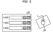
- FIG. 2 illustrates an example of the input device 200. As illustrated in FIG. 2 , it is allowed to display an image for operation 202 on the display device 300 so as to input the moving amount of each of an X-axis, a Y-axis and a Z-axis using an input device such as a keyboard or the like. In addition, it is allowed to input the moving amount of each of the X-axis, the Y-axis and the Z-axis using a mouse 204.
- an inputting method is set in advance for each of the X-axis, the Y-axis and the Z-axis so as to input the moving amounts of the X-axis, the Y-axis and the Z-axis independently of one another.
- the object may be set to move in the X-axis direction by dragging while left-clicking the mouse 204, to move in the Y-axis direction by dragging while right-clicking the mouse 204, and to move in the Z-axis direction by dragging while center-wheel-clicking the mouse 204.
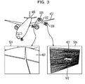
- FIG. 3 illustrates an observation example of a main wing when the reference object is an airplane and the target object is a virtual camera.
- the embodiment is an example in which the reference object is an airplane 400 and the target object is a virtual camera 500 as illustrated in FIG. 3 .
- the embodiment is not limited to the above example and a virtual object to be observed by the virtual camera 500 may be arbitrarily set as the reference object.
- the target object is not limited to the virtual camera 500 and a virtual object which is operated to move three-dimensionally around or within the reference object such as, for example, illumination that illuminates the reference object may be arbitrarily set as the target object.
- the virtual camera 500 displays the observed images 504 of the main wing 402 which are taken at various angles and distances while moving three-dimensionally around the main wing 402. For example, it is allowed to observe the main wing 402 from various directions while turning the virtual camera 500 on an orbit which is separated from the main wing 402 by a fixed distance.
- the main wing 402 it is allowed to observe a specific part of the main wing 402 in detail or to observe the entire of the main wing 402 by moving the virtual camera 500 in a direction that it comes near or goes away from the main wing 402 off the orbit. Further, it is allowed to analyze the flow of a fluid such as air or the like for the main wing 402 by a fluid analysis tool and display an analyzed image 506 on the display device 300 while operating the virtual camera 500 so as to move three-dimensionally around the main wing 402 as illustrate in FIG. 3 . A result of analysis of the flow of the air on a section 502 of the main wing 402 is displayed on the display device 300 as illustrated in FIG. 3 .
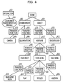
- FIG. 4 is a diagram illustrating an example of a scene graph.
- a scene graph has a tree structure which may materialize a concept for managing a displaying object in visualizing a reference object while operating the virtual camera 500 to move and is used by the developer of the object operation device 100.
- a lump of information on a camera, illumination, an airplane and the like is called an object and a parent object and a child object are connected together subordinately.
- an environment 602 is the parent object
- a camera 606 and illumination 608 will serve as the child objects.
- an object 604 is the parent object
- an airplane 610 and a background 612 will serve as the child objects.
- a main body 614, a main wing 616 and a tail wing 618 will serve as the child objects.
- a main wing body 620, a flap 620, a spoiler 624 and an aileron 626 will serve as the child objects.
- An operation performed on the parent object influences the child objects, for example, such that the positions of the main body 614, the main wing 616 and the tail wing 618 change with changing the position of the airplane 610. Therefore, the parent object and each of the child objects are connected together via a transfer function 630 (a coordinate transformation function) and the position coordinates of another object change with changing the position coordinates of one object.
- a transfer function 630 a coordinate transformation function
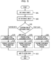
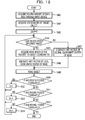
- FIG. 5 illustrates an example flowchart of the entire process of an object operation method.
- the object setting unit 115 sets a target object (S101). Specifically, the object setting unit 115 sets an object that has been selected from objects displayed on the display device 300 via the input device 200 in a target object setting mode as the target object.
- the virtual camera 500 has been selected and set as the target object.
- the object setting unit 115 sets a reference object (S102). Specifically, the object setting unit 115 sets an object which has been selected from objects displayed on the display device 300 via the input device 200 in a reference object setting mode as the reference object.
- the airplane 400 has been selected and surface data of the airplane 400 has been set as the reference object.
- the coordinate system generation unit 110 confirms whether the kind of the set reference object is surface data, line data or point data (S103). Since the kind of the reference object is the surface data in this embodiment, the coordinate system generation unit 110 generates a local coordinate system for the surface data (S104). Then, the move destination coordinates calculation unit 112 prepares a coordinate transformation module for the surface data (S105). Then, the move destination coordinates calculation unit 112 adds the prepared coordinate transformation module to the scene graph (S110). Incidentally, when the reference object is the line data, the coordinate system generation unit 110 generates a local coordinate system for the line data (S106) and the move destination coordinates calculation unit 112 prepares a coordinate transformation module for the line data (S107). When the reference object is the point data, the coordinate system generation unit 110 generates a local coordinate system for the point data (S108) and the move destination coordinates calculation unit 112 prepares a coordinate transformation module for the point data (S109).
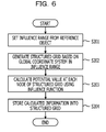
- FIG. 6 illustrates an example flowchart of a local coordinate system generating process.
- the coordinate system generation unit 110 sets an influence range from a reference object (S201).
- the influence range is a range indicating that a local coordinate system is generated so as to cover a domain which is separated from around the reference object by an amount.
- An initial value of the influence range may be set in advance or it may be arbitrarily set via the input device 200.
- the coordinate system generation unit 110 generates a structured grid based on a global coordinate system in the influence range (S202).
- the structured grid is a three-dimensional grid which is set around a reference object.
- the structured grid is generated so as to cover the influence range.
- the coordinate system generation unit 110 obtains a potential value at each node (a grid point) of the structured grid by using an influence function for the reference object (S203).
- the potential value is a value which is calculated according to the distance from the reference object. For example, the potential value "1" is obtained at a position which is the nearest the reference object and the value approaches "0" as the node goes away from the reference object and is reduced to "0" at an extension of the influence range.
- the coordinate system generation unit 110 stores the calculated potential value into each node of the structured grid (S204).
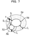
- FIG. 7 illustrates an example of calculation of a potential value using an influence function.
- FIG. 7 illustrates an example of calculating a potential value at a certain point P around two reference objects 700 and 702.
- a potential value ⁇ 1 for the reference object 700 at the point P is obtained by the following numerical formula 1 by using an influence function f 1 for the reference object 700.
- D 1 > C 1 f 1 is reduced to "0".
- a potential value ⁇ 2 for the reference object 702 at the point P is obtained by the following numerical formula 2 by using an influence function f 2 for the reference object 702.
- D 2 is a minimum Euclidean distance between the point P and the reference object 702
- C 2 is a distance between the reference object 702 and an extension 706 of the influence range for the reference object 702.
- f 2 is reduced to "0".
- a potential value ⁇ at the point P is obtained by the following numerical formula 3 by using an influence function f for the reference object 700 and the reference object 702.
- any influence function may be adopted as long as it is a decay function with which the potential value is reduced as the distance between the point P and the reference object approaches the distance up to the extension of the influence range.
- a fast marching method of generating a potential value according to a distance from a reference object may be used.
- the fast marching method is a method of obtaining an interface which is a phase-changeable dynamic profile model and is at a certain time t in a density distribution space. (see J. A. Sethian, Level set method and fast marching method, Cambridge University Press (1999 )).
- FIG. 8 illustrates an example flowchart of a process of calculating a local coordinate system.
- the coordinate system generation unit 110 generates a local coordinate system for each of n nodes (grid points) of a structured grid. For this purpose, the coordinate system generation unit 110 first initializes a variable i for performing looping n times to "0" (S301). Then, the coordinate system generation unit 110 judges whether i ⁇ n (S302). When i ⁇ n (Yes at S302), that is, when all the n nodes of the structured grid are not yet processed, the coordinate system generation unit 110 sets the potential value of the node i of the structured grid as a threshold value (S303).
- the coordinate system generation unit 110 selects eight nodes around the node i (S304). Then, the coordinate system generation unit 110 generates a surface for the threshold value using a marching cube method. As a result, an isosurface that links together the nodes of the equal potential values of the structured grid is formed.
- the coordinate system generation unit 110 judges whether one or more isosurfaces have been calculated (S306). When any isosurface is not calculated (No at S306), the coordinate system generation unit 110 generates a surface which is orthogonal to a line segment that links the node concerned with the reference object with a shortest distance as an isosurface (S307).
- the coordinate system generation unit 110 selects an isosurface which is the nearest to the reference object (S308). Then, the coordinate system generation unit 110 generates an X'-axis vector, a Y'-axis vector and a Z'-axis vector based on a first axis which is orthogonal to the isosurface, and second and third axes which are orthogonal to each other on the isosurface (S309). Specifically, the coordinate system generation unit 110 sets the first axis orthogonal to the isosurface as the Z'-axis vector.
- the coordinate system generation unit 110 sets a direction of an intersection between an X-Y plane and the isosurface in a global coordinate system as the X'-axis vector. Further, the coordinate system generation unit 110 sets a direction orthogonal to the X'-axis on the isosurface as the Y'-axis vector.
- the global coordinate system will be called the X-axis, Y-axis and Z-axis and the local coordinate system will be called the X'-axis, Y'-axis and Z'-axis in order to distinguish the global coordinate system from the local coordinate system.
- the coordinate system generation unit 110 stores the X'-axis, Y'-axis and Z'-axis vectors at the node i into the structured grid (S310). Then, the coordinate system generation unit 110 increments i (S311) and returns to S302 to perform a process for the next node of the structured grid.
- i ⁇ n is not established at S302 (No at S302), that is, all the n nodes of the structured grid have been processed, the coordinate system generation unit 110 terminates execution of the process.
- the X'-axis, Y'-axis and Z'-axis vectors are stored into each of the plurality of nodes of the structured grid.
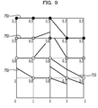
- FIG. 9 illustrates an example of potential values and isosurfaces on a structured grid.
- FIG. 9 illustrates an X-Y plane in the global coordinate system of a structured grid.
- potential values such as, for example, "0.3", “0.5", "1” and the like are stored into the respective nodes on the structured grid.
- an isosurface 750 is generated by linking nodes of equal potential values with each other.
- a continuous surface need not necessarily be generated.
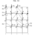
- FIG. 10 illustrates an example of a calculation of a Z'-axis vector at each point on a structured grid
- FIG. 11 illustrates an example of a calculation of an X'-axis vector at each point on a structured grid.
- a Z'-axis vector 752 is generated in a direction orthogonal to the isosurface 750 for each node of the structured grid.
- an X'-axis vector 754 is generated in a direction of an intersection between the isosurface 750 and the X-Y plane in the global coordinate system.
- the Y'-axis vector is generated in a direction orthogonal to the X'-axis vector on the isosurface 750.
- FIG. 12 illustrates an example flowchart of a process of calculating coordinates of a move destination of a target object.
- the move destination coordinates calculation unit 112 acquires a moving amount for each of the X'-axis, the Y'-axis and the Z'-axis through the input device 200 (S401). Then, the move destination coordinates calculation unit 112 acquires the current coordinates of a target object (S402). Then, the move destination coordinates calculation unit 112 executes the following moving process in order of the X'-axis, the Y'-axis and the Z'-axis.
- the move destination coordinates calculation unit 112 initializes each of a variable j for looping the X'-axis, a variable k for looping the Y'-axis and a variable m for looping the Z'-axis to "0" (S403).
- the move destination coordinates calculation unit 112 judges whether the coordinates of the operated object are within an influence range (S404).
- the move destination coordinates calculation unit 112 acquires a node of the structured grid which is the nearest to the coordinates of the operated object (S405). Since the operated object may not be positioned on the node of the structured grid in some cases, the nearest node of the structured grid is acquired. If the operated object is positioned on a node of the structured grid, the node of the structured grid on which the operated object is positioned will be acquired.
- the move destination coordinates calculation unit 112 generates a unit vector of a local coordinate system of the acquired node of the structured grid (S406). Specifically, the move destination coordinates calculation unit 112 generates the unit vector oriented in the direction of the X'-axis vector of the local coordinate system.
- the move destination coordinates calculation unit 112 when the coordinates of the operated object are not within the influence range at S404 (No at S404), since the operated object is positioned at a place deviating from the structured grid and any local coordinate system is not present, the move destination coordinates calculation unit 112 generates the unit vector of the global coordinate system (S407). Specifically, the move destination coordinates calculation unit 112 generates the unit vector oriented in the direction of the X-axis vector of the global coordinate system. Then, the moving process unit 114 moves the operated object according to the unit vector generated at S406 or S407 (S408).
- the move destination coordinates calculation unit 112 judges whether execution of an X'-axis moving process has been terminated (S409). Specifically, when the variable j has become larger than the amount of movement in the X'-axis direction, the move destination coordinates calculation unit 112 judges that execution of the X'-axis moving process has been terminated. When execution of the X'-axis moving process is not terminated (No at S409), the move destination coordinates calculation unit 112 increments j (S410) and returns to S404. That is, the move destination coordinates calculation unit 112 does not move the operated object far at one time and moves again and again the operated object by the amount corresponding to the unit vector each time until execution of the X'-axis moving process is terminated.
- the move destination coordinates calculation unit 112 judges whether execution of a Y'-axis moving process has been terminated (S411). When execution of the Y'-axis moving process is not terminated (No at S411), the move destination coordinates calculation unit 112 increments k (S412), returns to S404 and executes again the processes at S404 to S408.
- the move destination coordinates calculation unit 112 judges whether execution of a Z'-axis moving process has been terminated (S413).
- execution of the Z'-axis moving process is not terminated (No at S413), the move destination coordinates calculation unit 112 increments m (S414), returns to S404 and executes again the processes at S404 to S408 as in the case of the X'-axis moving process.
- execution of the Z'-axis moving process has been terminated (Yes at S413), the move destination coordinates calculation unit 112 terminates execution of the operated object moving process.
- the sight line direction of the virtual camera which is the operated object may be set to the negative direction of the Z'-axis.
- the sight line direction of the virtual camera is not fixed to a certain direction and may be arbitrarily set.
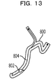
- FIG. 13 illustrates an example of a virtual organ and a virtual endoscope.
- a virtual endoscopic technique tubular data on a blood vessel or the large intestine of a subject is imaged by a medical imaging device such as a CT (Computed Tomography) device or an MRI (Magnetic Resonance Imaging) device.
- CT Computer Tomography
- MRI Magnetic Resonance Imaging
- an inner wall surface or the like of a blood vessel or the large intestine that a virtual endoscope 802 takes in its sight line direction is observed while operating the virtual endoscope 802 to move along a central axis 804 passing through, for example, the center of a tube within a virtual organ 800 which is the tubular data as illustrated in FIG. 13 .
- the virtual endoscope 802 which is the target object walks through along a fine tube of a blood vessel or the large intestine, it may be desirable to operate the target object simply and highly freely.
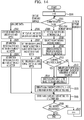
- FIG. 14 is an example flowchart of a local coordinate system calculating process executed when the reference object is line data.
- the virtual endoscope 802 is operated to move three-dimensionally not around the virtual organ 800 but within the virtual organ 800.
- the object setting unit 115 sets the line data passing through the tube center of the virtual organ 800 as the reference object.
- the potential value of each of nodes of a structured grid is obtained and stored into each node as in the case of the processes at S201 to S204 in FIG. 6 .
- the coordinate system generation unit 110 generates a local coordinate system for each of n nodes of the structured grid. For this purpose, first, the coordinate system generation unit 110 initializes a variable r for performing looping n times to "0" (S500). Then, the coordinate system generation unit 110 confirms whether a node i of the structured grid is positioned on the line data, on a tube boundary surface, in the tube boundary surface, or on the outside of the tube boundary (S501). When the node i is positioned on the line data, the coordinate system generation unit 110 sets the positive direction of the Line Data as the X'-axis vector (S502).
- the coordinate system generation unit 110 sets a direction orthogonal to the X'-axis vector on the X-Y plane of a global coordinate system as the Y'-axis vector (S503). Then, the coordinate system generation unit 110 sets a direction orthogonal to both the X'-axis vector and the Y'-axis vector as the Z'-axis vector (S504). Then, the coordinate system generation unit 110 stores the set X'-axis, Y'-axis and Z'-axis vectors into the corresponding node of the structured grid (S505).
- the coordinate system generation unit 110 sets the positive direction of the line data as the X'-axis vector (S506). Then, the coordinate system generation unit 110 sets a tangential direction of the tube boundary surface on an orthogonal surface orthogonal to the X'-axis vector as the Y'-axis vector (S507). Then, the coordinate system generation unit 110 sets a normal direction of the tube boundary surface as the Z'-axis vector (S508). Then, the coordinate system generation unit 110 stores the set X'-axis, Y'-axis and Z'-axis vectors into the corresponding node of the structured grid (S505).
- the coordinate system generation unit 110 sets the potential value of the node i as a threshold value (S509). Then, the coordinate system generation unit 110 selects eight nodes around the node i (S510). Then, the coordinate system generation unit 110 generates a surface for the threshold value using a marching cube method (S511). As a result, an isosurface that links together respective nodes having equal potential values of the structure grid is formed.
- the coordinate system generation unit 110 judges whether one or more isosurfaces have been calculated (S512). When any isosurface is not calculated (No at S512), the coordinate system generation unit 110 generates a surface orthogonal to a line segment that links the node with the reference object with a shortest distance as the isosurface (S513).
- the coordinate system generation unit 110 selects an isosurface which is the nearest to the reference object (S514). Then, the coordinate system generation unit 110 generates the local coordinate system of the X'-, Y'- and Z'-axes based on the first axis orthogonal to the isosurface and the second and third axes which are orthogonal to each other on the isosurface (S515). Specifically, the coordinate system generation unit 110 sets the first axis orthogonal to the isosurface as the Z'-axis vector.
- the coordinate system generation unit 110 sets a direction of an intersection between the X-Y plane and the isosurface in the global coordinate system as the X'-axis vector. Further, the coordinate system generation unit 110 sets a direction which is orthogonal to the X'-axis on the isosurface as the Y'-axis vector. Then, the coordinate system generation unit 110 stores the set X'-axis, Y'-axis and Z'-axis vectors into the corresponding node of the structured grid (S505).
- the coordinate system generation unit 110 judges whether execution of the local coordinate system generating process for all the nodes of the structured grid has been terminated (S518). Specifically, the coordinate system generation unit 110 judges whether r ⁇ n. When execution of the local coordinate system generating process for all the nodes of the structured grid is not terminated (No at S518), the coordinate system generation unit 110 increments r (S519) and returns to S501. On the other hand, when execution of the local coordinate system generating process for all the nodes of the structured grid has been terminated (Yes at S518), the coordinate system generation unit 110 terminates execution of the local coordinate system generating process.
- FIG. 15 illustrates an example of a local coordinate system when the reference object is line data.
- a direction along the line data is set as an X'-axis vector 804 for a node other than a node which is present on the line data and a node which is present on the outside of the tube boundary in nodes of a structured grid.
- a direction that the target object goes away from the line data on an orthogonal surface orthogonal to the X'-axis vector is set as a Z'-axis vector 808.
- a direction that the target object rotates around the line data on the orthogonal surface is set as a Y'-axis vector 806.
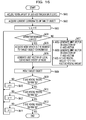
- FIG. 16 illustrates an example flowchart of a process of calculating the coordinates of a move destination of a virtual endoscope.
- the move destination coordinates calculation unit 112 acquires a moving amount for each of the X'-axis, Y'-axis and Z'-axis through the input device 200 (S601). Then, the move destination coordinates calculation unit 112 acquires the current coordinates of the target object (the endoscope 802) (S602).
- the move destination coordinates calculation unit 112 initializes each of a variable s for looping the X'-axis, a variable u for looping the Y'-axis and a variable v for looping the Z'-axis to "0" in order to execute the following moving process in order of the X'-axis, the Y'-axis and the Z'-axis (S603).
- the move destination coordinates calculation unit 112 judges whether the coordinates of the target object are within a tube boundary surface (S604).
- the move destination coordinates calculation unit 112 acquires a node of the structured grid which is the nearest to the coordinates of the target object (S605). Since the target object may not be positioned on the node of the structured grid in some cases, the node of the structured grid which is the nearest the coordinates is acquired. If the target object is positioned on a node of the structured grid, the node of the structured grid on which the target object is positioned will be acquired.
- the move destination coordinates calculation unit 112 generates a unit vector of the local coordinate system of the acquired node of the structured grid (S606).
- the move destination coordinates calculation unit 112 when the coordinates of the target object are not within the tube boundary surface (No at S604), the move destination coordinates calculation unit 112 generates the unit vector in the direction of the X'-axis vector of the local coordinate system at the node of the structured grid as for the X'-axis vector (S607).
- the moving process unit 114 moves the target object according to the unit vector generated at S606 or S607 (S608). That is, the move destination coordinates calculation unit 112 calculates the coordinates of the move destination of the target object based on the local coordinate system set for each node of the structured grid, and the moving process unit 114 moves the target object based on the calculated move destination coordinates.
- the move destination coordinate calculation unit 112 judges whether execution of the X'-axis moving process has been terminated (S609). Specifically, when s has became larger than the amount of movement in the X'-axis direction, the move destination coordinates calculation unit 112 judges that execution of the X'-axis moving process has been terminated. When execution of the X'-axis moving process is not terminated (No at S609), the move destination coordinates calculation unit 112 increments s (S610) and returns to S604. That is, the move destination coordinate calculation unit 112 does not move the target object far at one time and moves again and again the target object by the amount corresponding to the unit vector each time until execution of the X'-axis moving process has been terminated.
- the move destination coordinates calculation unit 112 judges whether execution of a Y'-axis moving process has been terminated (S611). When execution of the Y'-axis moving process is not terminated (No at S611), the move destination coordinates calculation unit 112 increments u (S612), returns to S604 and executes again the processes at S604 to S608 as in the case of the X'-axis moving process.
- the move destination coordinates calculation unit 112 judges whether a Z'-axis moving process has been executed (S613).
- the move destination coordinates calculation unit 112 increments V (S614), returns to S604, and executes again the processes at S604 to S608 as in the case of the X'-axis moving process.
- the process at S607 is different from the processes for the X'-axis and the Y'-axis.
- the move destination coordinates calculation unit 112 reduces the moving amount to "0" in order to prevent the target object from going away from the tube which is the virtual organ 800 due to positive movement in the Z'-axis direction.
- the move destination coordinates calculation unit 112 retains the moving amount (the negative moving amount) as it is in order to move the target object in a direction that it approaches the tube.
- the object operation device generates a local coordinate system for each of a plurality of points which are set around a reference object and moves a target object three-dimensionally based on the local coordinate system of each point. Therefore, according to the object operation device of the embodiment, since it may not be necessary to operate the target object on two screens, it may become possible to simply operate the target object to move three-dimensionally. In addition, according to the object operation device of the embodiment, since a path along which the target object moves is not set in advance and the local coordinate system of each of the plurality of points around the reference object is generated instead, it may become possible to move the target object three-dimensionally to an arbitrary position.
- the object operation device of the embodiment generates the local coordinate system based on the first axis which is orthogonal to the isosurface which has been formed based on the potential value of each of the plurality of points around the reference object, and the second and third axes which are orthogonal to each other on the isosurface. That is, the first axis is the axis directed such that the target object comes near or goes away from the reference object and the second and third axes are axes along which the target object moves on a surface separated from the reference object with a fixed distance. Therefore, according to the object operation device of the embodiment, it may become possible to observe the reference object from various directions while moving the target object such as the virtual camera or the like on a surface separated from the reference object with a fixed distance. In addition, it may become also possible to observe in details a specific part of the reference object or to observe the entire of the reference object while moving the target object in a direction it comes near or goes away from the reference object.
- the object operation device of the embodiment When the reference object is line data, the object operation device of the embodiment generates a local coordinate system for each of a plurality of points around the reference object based on a first axis directed along the line data, a second axis directed such that the target object goes away from the line data on an orthogonal surface which is orthogonal to the line data, and a third axis directed such that the target object rotates around the line data on the orthogonal surface. Therefore, according to the object operation device of the embodiment, when a virtual endoscope is to be moved three-dimensionally within tubular data, for example, on a blood vessel, the large intestine or the like, it may become possible to simply and highly freely operate it to move three-dimensionally.
- the object operation device of the embodiment converts a move command value in the local coordinate system of a target object which is input through the input device to a move command value in the global coordinate system and calculates the coordinates of a move destination of the target object based on the converted move command value. Therefore, according to the object operation device of the embodiment, it may become possible to operate the target object to move three-dimensionally by an intuitive operation.
- the invention is not limited to the above and functions which are substantially the same as those in the above mentioned embodiments may be implemented by executing an object operation program that has been prepared in advance by a computer. That is, the object operation program makes a computer execute a process of generating a local coordinate system for each of a plurality of points set around a reference object which will be a reference in operating a target object to move three-dimensionally.
- the object operation program makes the computer execute a process of calculating the coordinates of a move destination of the target object corresponding to a move command value of the target object which is input through the input device, based on the local coordinate system of each of the plurality of points generated by executing the local coordinate system generating process. Further, the object operation program makes the computer execute a process of moving the target object to the move destination coordinates that has been calculated by executing the move destination coordinates calculating process.
- the object operation program may be distributed to a computer via a communication network such as Internet or the like.
- the object operation program may be stored in a memory which is built into a computer or in a computer-readable recording medium such as a hard disk and the like and may be read out of the recording medium by the computer to be executed.
Landscapes
- Engineering & Computer Science (AREA)
- Theoretical Computer Science (AREA)
- General Engineering & Computer Science (AREA)
- Physics & Mathematics (AREA)
- General Physics & Mathematics (AREA)
- Computer Hardware Design (AREA)
- Software Systems (AREA)
- Computer Graphics (AREA)
- Architecture (AREA)
- Human Computer Interaction (AREA)
- Processing Or Creating Images (AREA)
- Image Generation (AREA)
- User Interface Of Digital Computer (AREA)
Applications Claiming Priority (1)
| Application Number | Priority Date | Filing Date | Title |
|---|---|---|---|
| JP2010225243A JP5609508B2 (ja) | 2010-10-04 | 2010-10-04 | オブジェクト操作装置、オブジェクト操作方法、およびオブジェクト操作プログラム |
Publications (3)
| Publication Number | Publication Date |
|---|---|
| EP2437221A2 true EP2437221A2 (fr) | 2012-04-04 |
| EP2437221A3 EP2437221A3 (fr) | 2017-01-25 |
| EP2437221B1 EP2437221B1 (fr) | 2017-12-27 |
Family
ID=45002571
Family Applications (1)
| Application Number | Title | Priority Date | Filing Date |
|---|---|---|---|
| EP11183767.0A Not-in-force EP2437221B1 (fr) | 2010-10-04 | 2011-10-04 | Dispositif, procédé et support de stockage lisible par ordinateur pour une opération de mouvement tridimensionnel d'un objet virtuel |
Country Status (3)
| Country | Link |
|---|---|
| US (1) | US8823700B2 (fr) |
| EP (1) | EP2437221B1 (fr) |
| JP (1) | JP5609508B2 (fr) |
Cited By (1)
| Publication number | Priority date | Publication date | Assignee | Title |
|---|---|---|---|---|
| CN103700145A (zh) * | 2013-12-25 | 2014-04-02 | 北京像素软件科技股份有限公司 | 一种实现图像仿真的方法 |
Families Citing this family (6)
| Publication number | Priority date | Publication date | Assignee | Title |
|---|---|---|---|---|
| DE102009058802B4 (de) * | 2009-12-18 | 2018-03-29 | Airbus Operations Gmbh | Anordnung zur kombinierten Darstellung eines realen und eines virtuellen Modells |
| JP5586648B2 (ja) | 2012-03-30 | 2014-09-10 | 株式会社東芝 | 永久磁石とそれを用いたモータおよび発電機 |
| DE102014009299B4 (de) * | 2014-06-26 | 2025-10-16 | Audi Ag | Verfahren zum Betreiben einer Virtual-Reality-Brille und System mit einer Virtual-Reality-Brille |
| US10777018B2 (en) * | 2017-05-17 | 2020-09-15 | Bespoke, Inc. | Systems and methods for determining the scale of human anatomy from images |
| CN108629847A (zh) * | 2018-05-07 | 2018-10-09 | 网易(杭州)网络有限公司 | 虚拟对象移动路径生成方法、装置、存储介质及电子设备 |
| US11900822B2 (en) * | 2020-12-18 | 2024-02-13 | The Boeing Company | Dynamic approach procedure system |
Citations (1)
| Publication number | Priority date | Publication date | Assignee | Title |
|---|---|---|---|---|
| JPH10232943A (ja) | 1997-02-18 | 1998-09-02 | Konami Co Ltd | ポリゴンの張付け方法、その装置及びシミュレータ |
Family Cites Families (9)
| Publication number | Priority date | Publication date | Assignee | Title |
|---|---|---|---|---|
| JP3830188B2 (ja) * | 1995-12-18 | 2006-10-04 | 株式会社バンダイナムコゲームス | ゲーム用画像合成装置 |
| US6657627B1 (en) * | 1997-02-18 | 2003-12-02 | Konami Co., Ltd. | Video simulation system for calculating distance between characters and applying polygon to polygon plane |
| JP3928229B2 (ja) * | 1997-11-28 | 2007-06-13 | ソニー株式会社 | 表示制御装置および表示制御方法、並びに記録媒体 |
| US6421048B1 (en) * | 1998-07-17 | 2002-07-16 | Sensable Technologies, Inc. | Systems and methods for interacting with virtual objects in a haptic virtual reality environment |
| JP4349932B2 (ja) * | 2004-02-26 | 2009-10-21 | 株式会社バンダイナムコゲームス | プログラム、情報記憶媒体及びゲーム装置 |
| JP4863435B2 (ja) * | 2005-05-13 | 2012-01-25 | 任天堂株式会社 | ゲームプログラム、ゲーム装置、ゲームシステム、およびゲーム処理方法 |
| JP4776978B2 (ja) * | 2005-05-18 | 2011-09-21 | 株式会社バンダイナムコゲームス | プログラム、情報記憶媒体及びゲーム装置 |
| JP5095122B2 (ja) * | 2006-05-01 | 2012-12-12 | 任天堂株式会社 | ゲームプログラムおよびゲーム装置 |
| AU2009282724B2 (en) * | 2008-08-22 | 2014-12-04 | Google Inc. | Navigation in a three dimensional environment on a mobile device |
-
2010
- 2010-10-04 JP JP2010225243A patent/JP5609508B2/ja not_active Expired - Fee Related
-
2011
- 2011-09-29 US US13/248,504 patent/US8823700B2/en not_active Expired - Fee Related
- 2011-10-04 EP EP11183767.0A patent/EP2437221B1/fr not_active Not-in-force
Patent Citations (1)
| Publication number | Priority date | Publication date | Assignee | Title |
|---|---|---|---|---|
| JPH10232943A (ja) | 1997-02-18 | 1998-09-02 | Konami Co Ltd | ポリゴンの張付け方法、その装置及びシミュレータ |
Non-Patent Citations (1)
| Title |
|---|
| J. A. SETHIAN: "Level set method and fast marching method", 1999, CAMBRIDGE UNIVERSITY PRESS |
Cited By (1)
| Publication number | Priority date | Publication date | Assignee | Title |
|---|---|---|---|---|
| CN103700145A (zh) * | 2013-12-25 | 2014-04-02 | 北京像素软件科技股份有限公司 | 一种实现图像仿真的方法 |
Also Published As
| Publication number | Publication date |
|---|---|
| US20120081365A1 (en) | 2012-04-05 |
| JP2012079182A (ja) | 2012-04-19 |
| EP2437221A3 (fr) | 2017-01-25 |
| JP5609508B2 (ja) | 2014-10-22 |
| EP2437221B1 (fr) | 2017-12-27 |
| US8823700B2 (en) | 2014-09-02 |
Similar Documents
| Publication | Publication Date | Title |
|---|---|---|
| EP2437221B1 (fr) | Dispositif, procédé et support de stockage lisible par ordinateur pour une opération de mouvement tridimensionnel d'un objet virtuel | |
| CN101166470B (zh) | 图像显示装置及图像显示方法 | |
| JP5355074B2 (ja) | 3次元形状データ処理装置、3次元形状データ処理方法及びプログラム | |
| US9214139B2 (en) | Image display apparatus and image display method | |
| JP6359868B2 (ja) | 3次元データ表示装置、3次元データ表示方法、及び3次元データ表示プログラム | |
| US10395380B2 (en) | Image processing apparatus, image processing method, and storage medium | |
| WO2015010745A1 (fr) | Segmentation de données d'images à partir de plusieurs modalités | |
| JP2009072317A (ja) | 医療用チューブ操作支援システム | |
| EP2168492A1 (fr) | Appareil d'affichage d'image médicale, procédé d'affichage d'image médicale, et programme d'affichage d'image médicale | |
| US20100305908A1 (en) | Harness verification apparatus, harness verification method and storage medium | |
| WO2013171779A1 (fr) | Dispositif d'assistance à l'installation d'une tuyauterie ou d'un câblage | |
| WO2017180097A1 (fr) | Alignement déformable d'entrées peropératoire et préopératoire à l'aide de modèles de mélange génératifs et d'une déformation biomécanique | |
| CN102356408A (zh) | 场景视图的可视化 | |
| CN101889284B (zh) | 导航引导 | |
| EP2727078B1 (fr) | Zoom sur des images médicales | |
| JP2016157174A (ja) | 3次元空間データ補間プログラム、ならびに、それを組み合わせて実現する形状発生プログラム | |
| JP2009266251A (ja) | 電子関数グラフ表示装置、座標取得装置、電子関数グラフ表示方法、座標取得方法、及びプログラム | |
| US12168299B2 (en) | Information processing device, control method, and storage medium | |
| EP3866120A1 (fr) | Système de segmentation d'images | |
| JP2007098028A (ja) | モデリング装置、モデリング方法、領域抽出装置、およびプログラム | |
| CN113749680B (zh) | 扫描定位方法、装置、存储介质及计算机设备 | |
| Audette et al. | A topologically faithful, tissue-guided, spatially varying meshing strategy for computing patient-specific head models for endoscopic pituitary surgery simulation | |
| JP5290138B2 (ja) | メッシュ変更装置、メッシュ変更方法、およびプログラム | |
| JP4736755B2 (ja) | モデリング装置、領域抽出装置、モデリング方法及びプログラム | |
| JP2007159927A (ja) | モデリング装置、モデリング方法、領域抽出装置、領域抽出方法及びプログラム |
Legal Events
| Date | Code | Title | Description |
|---|---|---|---|
| PUAI | Public reference made under article 153(3) epc to a published international application that has entered the european phase |
Free format text: ORIGINAL CODE: 0009012 |
|
| AK | Designated contracting states |
Kind code of ref document: A2 Designated state(s): AL AT BE BG CH CY CZ DE DK EE ES FI FR GB GR HR HU IE IS IT LI LT LU LV MC MK MT NL NO PL PT RO RS SE SI SK SM TR |
|
| AX | Request for extension of the european patent |
Extension state: BA ME |
|
| PUAL | Search report despatched |
Free format text: ORIGINAL CODE: 0009013 |
|
| AK | Designated contracting states |
Kind code of ref document: A3 Designated state(s): AL AT BE BG CH CY CZ DE DK EE ES FI FR GB GR HR HU IE IS IT LI LT LU LV MC MK MT NL NO PL PT RO RS SE SI SK SM TR |
|
| AX | Request for extension of the european patent |
Extension state: BA ME |
|
| RIC1 | Information provided on ipc code assigned before grant |
Ipc: G06T 19/20 20110101AFI20161216BHEP Ipc: G06F 3/048 20130101ALI20161216BHEP |
|
| 17P | Request for examination filed |
Effective date: 20170330 |
|
| RBV | Designated contracting states (corrected) |
Designated state(s): AL AT BE BG CH CY CZ DE DK EE ES FI FR GB GR HR HU IE IS IT LI LT LU LV MC MK MT NL NO PL PT RO RS SE SI SK SM TR |
|
| GRAP | Despatch of communication of intention to grant a patent |
Free format text: ORIGINAL CODE: EPIDOSNIGR1 |
|
| INTG | Intention to grant announced |
Effective date: 20170926 |
|
| RIN1 | Information on inventor provided before grant (corrected) |
Inventor name: NAKAGAWA, MACHIKO |
|
| GRAS | Grant fee paid |
Free format text: ORIGINAL CODE: EPIDOSNIGR3 |
|
| GRAA | (expected) grant |
Free format text: ORIGINAL CODE: 0009210 |
|
| AK | Designated contracting states |
Kind code of ref document: B1 Designated state(s): AL AT BE BG CH CY CZ DE DK EE ES FI FR GB GR HR HU IE IS IT LI LT LU LV MC MK MT NL NO PL PT RO RS SE SI SK SM TR |
|
| REG | Reference to a national code |
Ref country code: GB Ref legal event code: FG4D |
|
| REG | Reference to a national code |
Ref country code: CH Ref legal event code: EP |
|
| REG | Reference to a national code |
Ref country code: AT Ref legal event code: REF Ref document number: 958904 Country of ref document: AT Kind code of ref document: T Effective date: 20180115 |
|
| REG | Reference to a national code |
Ref country code: IE Ref legal event code: FG4D |
|
| REG | Reference to a national code |
Ref country code: DE Ref legal event code: R096 Ref document number: 602011044519 Country of ref document: DE |
|
| PG25 | Lapsed in a contracting state [announced via postgrant information from national office to epo] |
Ref country code: LT Free format text: LAPSE BECAUSE OF FAILURE TO SUBMIT A TRANSLATION OF THE DESCRIPTION OR TO PAY THE FEE WITHIN THE PRESCRIBED TIME-LIMIT Effective date: 20171227 Ref country code: NO Free format text: LAPSE BECAUSE OF FAILURE TO SUBMIT A TRANSLATION OF THE DESCRIPTION OR TO PAY THE FEE WITHIN THE PRESCRIBED TIME-LIMIT Effective date: 20180327 Ref country code: FI Free format text: LAPSE BECAUSE OF FAILURE TO SUBMIT A TRANSLATION OF THE DESCRIPTION OR TO PAY THE FEE WITHIN THE PRESCRIBED TIME-LIMIT Effective date: 20171227 |
|
| REG | Reference to a national code |
Ref country code: NL Ref legal event code: MP Effective date: 20171227 |
|
| REG | Reference to a national code |
Ref country code: LT Ref legal event code: MG4D |
|
| REG | Reference to a national code |
Ref country code: AT Ref legal event code: MK05 Ref document number: 958904 Country of ref document: AT Kind code of ref document: T Effective date: 20171227 |
|
| PG25 | Lapsed in a contracting state [announced via postgrant information from national office to epo] |
Ref country code: BG Free format text: LAPSE BECAUSE OF FAILURE TO SUBMIT A TRANSLATION OF THE DESCRIPTION OR TO PAY THE FEE WITHIN THE PRESCRIBED TIME-LIMIT Effective date: 20180327 Ref country code: GR Free format text: LAPSE BECAUSE OF FAILURE TO SUBMIT A TRANSLATION OF THE DESCRIPTION OR TO PAY THE FEE WITHIN THE PRESCRIBED TIME-LIMIT Effective date: 20180328 Ref country code: LV Free format text: LAPSE BECAUSE OF FAILURE TO SUBMIT A TRANSLATION OF THE DESCRIPTION OR TO PAY THE FEE WITHIN THE PRESCRIBED TIME-LIMIT Effective date: 20171227 Ref country code: RS Free format text: LAPSE BECAUSE OF FAILURE TO SUBMIT A TRANSLATION OF THE DESCRIPTION OR TO PAY THE FEE WITHIN THE PRESCRIBED TIME-LIMIT Effective date: 20171227 Ref country code: HR Free format text: LAPSE BECAUSE OF FAILURE TO SUBMIT A TRANSLATION OF THE DESCRIPTION OR TO PAY THE FEE WITHIN THE PRESCRIBED TIME-LIMIT Effective date: 20171227 |
|
| PG25 | Lapsed in a contracting state [announced via postgrant information from national office to epo] |
Ref country code: NL Free format text: LAPSE BECAUSE OF FAILURE TO SUBMIT A TRANSLATION OF THE DESCRIPTION OR TO PAY THE FEE WITHIN THE PRESCRIBED TIME-LIMIT Effective date: 20171227 |
|
| PG25 | Lapsed in a contracting state [announced via postgrant information from national office to epo] |
Ref country code: CZ Free format text: LAPSE BECAUSE OF FAILURE TO SUBMIT A TRANSLATION OF THE DESCRIPTION OR TO PAY THE FEE WITHIN THE PRESCRIBED TIME-LIMIT Effective date: 20171227 Ref country code: SK Free format text: LAPSE BECAUSE OF FAILURE TO SUBMIT A TRANSLATION OF THE DESCRIPTION OR TO PAY THE FEE WITHIN THE PRESCRIBED TIME-LIMIT Effective date: 20171227 Ref country code: EE Free format text: LAPSE BECAUSE OF FAILURE TO SUBMIT A TRANSLATION OF THE DESCRIPTION OR TO PAY THE FEE WITHIN THE PRESCRIBED TIME-LIMIT Effective date: 20171227 Ref country code: CY Free format text: LAPSE BECAUSE OF FAILURE TO SUBMIT A TRANSLATION OF THE DESCRIPTION OR TO PAY THE FEE WITHIN THE PRESCRIBED TIME-LIMIT Effective date: 20171227 Ref country code: ES Free format text: LAPSE BECAUSE OF FAILURE TO SUBMIT A TRANSLATION OF THE DESCRIPTION OR TO PAY THE FEE WITHIN THE PRESCRIBED TIME-LIMIT Effective date: 20171227 |
|
| REG | Reference to a national code |
Ref country code: FR Ref legal event code: PLFP Year of fee payment: 8 |
|
| PG25 | Lapsed in a contracting state [announced via postgrant information from national office to epo] |
Ref country code: IT Free format text: LAPSE BECAUSE OF FAILURE TO SUBMIT A TRANSLATION OF THE DESCRIPTION OR TO PAY THE FEE WITHIN THE PRESCRIBED TIME-LIMIT Effective date: 20171227 Ref country code: AT Free format text: LAPSE BECAUSE OF FAILURE TO SUBMIT A TRANSLATION OF THE DESCRIPTION OR TO PAY THE FEE WITHIN THE PRESCRIBED TIME-LIMIT Effective date: 20171227 Ref country code: PL Free format text: LAPSE BECAUSE OF FAILURE TO SUBMIT A TRANSLATION OF THE DESCRIPTION OR TO PAY THE FEE WITHIN THE PRESCRIBED TIME-LIMIT Effective date: 20171227 Ref country code: SM Free format text: LAPSE BECAUSE OF FAILURE TO SUBMIT A TRANSLATION OF THE DESCRIPTION OR TO PAY THE FEE WITHIN THE PRESCRIBED TIME-LIMIT Effective date: 20171227 Ref country code: IS Free format text: LAPSE BECAUSE OF FAILURE TO SUBMIT A TRANSLATION OF THE DESCRIPTION OR TO PAY THE FEE WITHIN THE PRESCRIBED TIME-LIMIT Effective date: 20180427 Ref country code: RO Free format text: LAPSE BECAUSE OF FAILURE TO SUBMIT A TRANSLATION OF THE DESCRIPTION OR TO PAY THE FEE WITHIN THE PRESCRIBED TIME-LIMIT Effective date: 20171227 |
|
| REG | Reference to a national code |
Ref country code: DE Ref legal event code: R097 Ref document number: 602011044519 Country of ref document: DE |
|
| PLBE | No opposition filed within time limit |
Free format text: ORIGINAL CODE: 0009261 |
|
| STAA | Information on the status of an ep patent application or granted ep patent |
Free format text: STATUS: NO OPPOSITION FILED WITHIN TIME LIMIT |
|
| PG25 | Lapsed in a contracting state [announced via postgrant information from national office to epo] |
Ref country code: DK Free format text: LAPSE BECAUSE OF FAILURE TO SUBMIT A TRANSLATION OF THE DESCRIPTION OR TO PAY THE FEE WITHIN THE PRESCRIBED TIME-LIMIT Effective date: 20171227 |
|
| 26N | No opposition filed |
Effective date: 20180928 |
|
| PG25 | Lapsed in a contracting state [announced via postgrant information from national office to epo] |
Ref country code: SI Free format text: LAPSE BECAUSE OF FAILURE TO SUBMIT A TRANSLATION OF THE DESCRIPTION OR TO PAY THE FEE WITHIN THE PRESCRIBED TIME-LIMIT Effective date: 20171227 |
|
| REG | Reference to a national code |
Ref country code: CH Ref legal event code: PL |
|
| REG | Reference to a national code |
Ref country code: BE Ref legal event code: MM Effective date: 20181031 |
|
| PG25 | Lapsed in a contracting state [announced via postgrant information from national office to epo] |
Ref country code: LU Free format text: LAPSE BECAUSE OF NON-PAYMENT OF DUE FEES Effective date: 20181004 Ref country code: MC Free format text: LAPSE BECAUSE OF FAILURE TO SUBMIT A TRANSLATION OF THE DESCRIPTION OR TO PAY THE FEE WITHIN THE PRESCRIBED TIME-LIMIT Effective date: 20171227 |
|
| REG | Reference to a national code |
Ref country code: IE Ref legal event code: MM4A |
|
| PG25 | Lapsed in a contracting state [announced via postgrant information from national office to epo] |
Ref country code: CH Free format text: LAPSE BECAUSE OF NON-PAYMENT OF DUE FEES Effective date: 20181031 Ref country code: LI Free format text: LAPSE BECAUSE OF NON-PAYMENT OF DUE FEES Effective date: 20181031 Ref country code: BE Free format text: LAPSE BECAUSE OF NON-PAYMENT OF DUE FEES Effective date: 20181031 |
|
| PG25 | Lapsed in a contracting state [announced via postgrant information from national office to epo] |
Ref country code: IE Free format text: LAPSE BECAUSE OF NON-PAYMENT OF DUE FEES Effective date: 20181004 |
|
| PG25 | Lapsed in a contracting state [announced via postgrant information from national office to epo] |
Ref country code: MT Free format text: LAPSE BECAUSE OF NON-PAYMENT OF DUE FEES Effective date: 20181004 |
|
| PG25 | Lapsed in a contracting state [announced via postgrant information from national office to epo] |
Ref country code: TR Free format text: LAPSE BECAUSE OF FAILURE TO SUBMIT A TRANSLATION OF THE DESCRIPTION OR TO PAY THE FEE WITHIN THE PRESCRIBED TIME-LIMIT Effective date: 20171227 |
|
| PG25 | Lapsed in a contracting state [announced via postgrant information from national office to epo] |
Ref country code: PT Free format text: LAPSE BECAUSE OF FAILURE TO SUBMIT A TRANSLATION OF THE DESCRIPTION OR TO PAY THE FEE WITHIN THE PRESCRIBED TIME-LIMIT Effective date: 20171227 |
|
| PG25 | Lapsed in a contracting state [announced via postgrant information from national office to epo] |
Ref country code: MK Free format text: LAPSE BECAUSE OF NON-PAYMENT OF DUE FEES Effective date: 20171227 Ref country code: HU Free format text: LAPSE BECAUSE OF FAILURE TO SUBMIT A TRANSLATION OF THE DESCRIPTION OR TO PAY THE FEE WITHIN THE PRESCRIBED TIME-LIMIT; INVALID AB INITIO Effective date: 20111004 Ref country code: SE Free format text: LAPSE BECAUSE OF FAILURE TO SUBMIT A TRANSLATION OF THE DESCRIPTION OR TO PAY THE FEE WITHIN THE PRESCRIBED TIME-LIMIT Effective date: 20171227 |
|
| PG25 | Lapsed in a contracting state [announced via postgrant information from national office to epo] |
Ref country code: AL Free format text: LAPSE BECAUSE OF FAILURE TO SUBMIT A TRANSLATION OF THE DESCRIPTION OR TO PAY THE FEE WITHIN THE PRESCRIBED TIME-LIMIT Effective date: 20171227 |
|
| PGFP | Annual fee paid to national office [announced via postgrant information from national office to epo] |
Ref country code: GB Payment date: 20200925 Year of fee payment: 10 Ref country code: FR Payment date: 20200914 Year of fee payment: 10 |
|
| REG | Reference to a national code |
Ref country code: DE Ref legal event code: R082 Ref document number: 602011044519 Country of ref document: DE Representative=s name: HL KEMPNER PATENTANWALT, RECHTSANWALT, SOLICIT, DE |
|
| PGFP | Annual fee paid to national office [announced via postgrant information from national office to epo] |
Ref country code: DE Payment date: 20200922 Year of fee payment: 10 |
|
| REG | Reference to a national code |
Ref country code: DE Ref legal event code: R119 Ref document number: 602011044519 Country of ref document: DE |
|
| GBPC | Gb: european patent ceased through non-payment of renewal fee |
Effective date: 20211004 |
|
| PG25 | Lapsed in a contracting state [announced via postgrant information from national office to epo] |
Ref country code: GB Free format text: LAPSE BECAUSE OF NON-PAYMENT OF DUE FEES Effective date: 20211004 Ref country code: DE Free format text: LAPSE BECAUSE OF NON-PAYMENT OF DUE FEES Effective date: 20220503 |
|
| PG25 | Lapsed in a contracting state [announced via postgrant information from national office to epo] |
Ref country code: FR Free format text: LAPSE BECAUSE OF NON-PAYMENT OF DUE FEES Effective date: 20211031 |