EP2436858B1 - Schließzylinder für ein Schloss - Google Patents
Schließzylinder für ein Schloss Download PDFInfo
- Publication number
- EP2436858B1 EP2436858B1 EP11007989.4A EP11007989A EP2436858B1 EP 2436858 B1 EP2436858 B1 EP 2436858B1 EP 11007989 A EP11007989 A EP 11007989A EP 2436858 B1 EP2436858 B1 EP 2436858B1
- Authority
- EP
- European Patent Office
- Prior art keywords
- shaft
- housing
- coupling
- locking
- recess
- Prior art date
- Legal status (The legal status is an assumption and is not a legal conclusion. Google has not performed a legal analysis and makes no representation as to the accuracy of the status listed.)
- Active
Links
Images
Classifications
-
- E—FIXED CONSTRUCTIONS
- E05—LOCKS; KEYS; WINDOW OR DOOR FITTINGS; SAFES
- E05B—LOCKS; ACCESSORIES THEREFOR; HANDCUFFS
- E05B17/00—Accessories in connection with locks
- E05B17/04—Devices for coupling the turning cylinder of a single or a double cylinder lock with the bolt operating member
- E05B17/047—Devices for coupling the turning cylinder of a single or a double cylinder lock with the bolt operating member with rotating output elements forming part of cylinder locks, e.g. locking cams of double cylinder locks
-
- E—FIXED CONSTRUCTIONS
- E05—LOCKS; KEYS; WINDOW OR DOOR FITTINGS; SAFES
- E05B—LOCKS; ACCESSORIES THEREFOR; HANDCUFFS
- E05B47/00—Operating or controlling locks or other fastening devices by electric or magnetic means
- E05B47/06—Controlling mechanically-operated bolts by electro-magnetically-operated detents
- E05B47/0611—Cylinder locks with electromagnetic control
- E05B47/0615—Cylinder locks with electromagnetic control operated by handles, e.g. by knobs
-
- E—FIXED CONSTRUCTIONS
- E05—LOCKS; KEYS; WINDOW OR DOOR FITTINGS; SAFES
- E05B—LOCKS; ACCESSORIES THEREFOR; HANDCUFFS
- E05B47/00—Operating or controlling locks or other fastening devices by electric or magnetic means
- E05B47/06—Controlling mechanically-operated bolts by electro-magnetically-operated detents
- E05B47/0611—Cylinder locks with electromagnetic control
- E05B47/0638—Cylinder locks with electromagnetic control by disconnecting the rotor
- E05B47/0642—Cylinder locks with electromagnetic control by disconnecting the rotor axially, i.e. with an axially disengaging coupling element
-
- E—FIXED CONSTRUCTIONS
- E05—LOCKS; KEYS; WINDOW OR DOOR FITTINGS; SAFES
- E05B—LOCKS; ACCESSORIES THEREFOR; HANDCUFFS
- E05B9/00—Lock casings or latch-mechanism casings ; Fastening locks or fasteners or parts thereof to the wing
- E05B9/04—Casings of cylinder locks
- E05B9/041—Double cylinder locks
-
- E—FIXED CONSTRUCTIONS
- E05—LOCKS; KEYS; WINDOW OR DOOR FITTINGS; SAFES
- E05B—LOCKS; ACCESSORIES THEREFOR; HANDCUFFS
- E05B47/00—Operating or controlling locks or other fastening devices by electric or magnetic means
- E05B47/0001—Operating or controlling locks or other fastening devices by electric or magnetic means with electric actuators; Constructional features thereof
- E05B2047/0014—Constructional features of actuators or power transmissions therefor
- E05B2047/0018—Details of actuator transmissions
- E05B2047/0023—Nuts or nut-like elements moving along a driven threaded axle
-
- E—FIXED CONSTRUCTIONS
- E05—LOCKS; KEYS; WINDOW OR DOOR FITTINGS; SAFES
- E05B—LOCKS; ACCESSORIES THEREFOR; HANDCUFFS
- E05B47/00—Operating or controlling locks or other fastening devices by electric or magnetic means
- E05B47/0001—Operating or controlling locks or other fastening devices by electric or magnetic means with electric actuators; Constructional features thereof
- E05B2047/0014—Constructional features of actuators or power transmissions therefor
- E05B2047/0018—Details of actuator transmissions
- E05B2047/0026—Clutches, couplings or braking arrangements
- E05B2047/0031—Clutches, couplings or braking arrangements of the elastic type
-
- E—FIXED CONSTRUCTIONS
- E05—LOCKS; KEYS; WINDOW OR DOOR FITTINGS; SAFES
- E05B—LOCKS; ACCESSORIES THEREFOR; HANDCUFFS
- E05B47/00—Operating or controlling locks or other fastening devices by electric or magnetic means
- E05B47/0001—Operating or controlling locks or other fastening devices by electric or magnetic means with electric actuators; Constructional features thereof
- E05B47/0012—Operating or controlling locks or other fastening devices by electric or magnetic means with electric actuators; Constructional features thereof with rotary electromotors
Definitions
- the present invention relates to a lock cylinder for a lock, in particular for a mortise lock for a door, with a housing and aligned in the longitudinal direction of the housing bore for receiving a shaft and with a housing dividing the housing into two sections recess, in which recess a with respect to the Housing rotatable locking lug is arranged.
- the invention relates to a lock cylinder for a lock, in particular for a mortise lock for a door, with a housing and a rotatably mounted in a longitudinal bore of the housing shaft, with respect to the housing about a, defined by the shaft axis of rotation locking nose and with a by means of a drive operable coupling, by means of which a rotationally fixed coupling between the shaft and the locking lug can be produced as a function of the verification of an authorization code.
- Locks with generic lock cylinders are known from the prior art basically, both in the embodiment as a purely mechanically operating lock and in the embodiment as an electronically operating lock or combinations thereof, so that it is not a separate printed evidence at this point requirement.
- Locks with generic lock cylinders are used, inter alia, in the entrance door area in door leaves, via a shaft of the lock cylinder, the opening and closing of the door, that is, the movement of a trap and / or a bolt is performed.
- the shaft on a door outside a handle in particular a freely rotatable knob, which only allows actuation of the case or the bolt when previously an authorization code has been verified by the lock cylinder.
- Door inside is also arranged a handle whose operation allows the operation of the case or the bolt regardless of the presence of the verification of an authorization code. This ensures that the door can always be opened from the inside, regardless of the presence of a valid authorization code.
- the authorization code can be entered mechanically or electronically. For example, it is the secret of a conventional mechanical or electronic key.
- the authorization code can be entered in the case of electronic locks, for example wirelessly via radio, via an input keyboard or the like. Such locks are for example from the DE 10 2004 056 988 A1 or from the EP 0 588 209 A1 known.
- a construction is known for a lock cylinder, wherein the shaft of the lock cylinder is divided into two sections and has a first and a second section.
- the two sections of the shaft can be brought into operative connection with each other by means of a coupling.
- the coupling between two coaxially arranged parts of the first portion of the shaft is arranged and has two guided in recesses of the second part of the first portion of the shaft rolling body, which is used to establish the operative connection between the first part and the second part of the first portion Shaft by means of a movable slide in the circumferential direction of the first part of the first portion of the shaft extending recesses are inserted.
- the slide is actuated by means of a drive.
- the disclosure DE 20 2008 013 172 U1 a generic lock cylinder, which has made it its business, a lock, as it is from the DE 102 25 490 A1 is known to improve in terms of assembly.
- the drive for actuating the clutch is arranged in the shaft.
- the shaft has a shaft journal which engages in a bore of the locking lug.
- the shaft journal comprises a radially movable pin by means of the drive, which is guided in a bore of the shaft journal. In the coupled state, the pin is moved radially outward and engages for the purpose of coupling in a recess in the wall of the bore of the locking lug.
- the assembly of a generic lock cylinder should be further simplified.
- the invention proposes a lock cylinder for a lock, in particular for a mortise lock for a door, with a housing and a rotatably mounted in a longitudinal bore of the housing shaft, with respect to the housing about a defined axis defined by the axis of rotation locking nose and with a by means of a drive operable clutch, by means of which a rotationally fixed coupling between the shaft and the locking lug can be produced in dependence on the verification of an authorization code, wherein the clutch rotatably connected to the shaft, formed by the drive as a rotating electric machine axially movable to the shaft slide comprises, which slide is connected via an energy storage device, in particular a spring element to the drive and engages in the coupled state of the coupling in the locking nose, wherein the energy storage by the drive for a coupling operation and for a Entku buffers stored energy and drives the slide during the coupling and uncoupling process.
- the invention makes it possible to reduce the number of required components in a coupling, which preferably allows a direct coupling between the shaft and the locking lug. Costs such as component costs, assembly costs and the like can be reduced. Characterized in that instead of a complex coupling assembly in the prior art according to the invention, only a slider and a power storage are provided, the number of parts to be mounted can be significantly reduced. This not only reduces costs, but it simplifies the construction of the lock cylinder and also increases the reliability of the lock cylinder or the lock. Elaborate constructions for power diversion to mechanically realize the coupling can be avoided. So it is only necessary in the invention to provide the slide, which can engage in a corresponding recess of the locking lug.
- the slide can be driven by the mediation of the energy storage. This makes it possible to temporarily store the energy provided by the drive for a coupling process or for a decoupling operation, until the coupling process or the decoupling process can actually be carried out.
- a relative Preferred position between the locking lug and the shaft is required, the energy for the actuation of the clutch in the energy storage can be stored until the achievement of this preferred position.
- the preferred position may be formed by one or more relative rotational positions.
- the drive therefore does not need to remain activated until the actual operation of coupling or uncoupling is carried out. This type of drive thus allows a very low energy consumption.
- the invention proves in electronic locks, which are powered by a battery with electrical energy.
- the lock cylinder according to the invention allows a long service life of the electronic lock without battery change. Furthermore, it proves to be advantageous that only a few components for coupling or decoupling must be operated. A further reduction in energy consumption can be achieved. Due to the small number of components at the same time increases the reliability of the lock cylinder.
- the energy accumulator can be formed by a spring element.
- the slide and / or the energy accumulator are preferably arranged on the shaft. This arrangement can also be combined particularly advantageously with the arrangement of the drive on the shaft. Of course, an arrangement can be provided elsewhere, for example in the housing of the lock cylinder.
- the slide can be moved substantially axially relative to the shaft.
- its function can be decoupled from a rotational movement of the shaft, in particular when arranged on the shaft, because the coupling state can only be achieved by an axial displacement of the slide.
- a coupling effect may possibly be unintentionally achieved. This problem is completely avoided in the embodiment according to the invention.
- the slider may be axially guided on the shaft, so that it does not depend on accelerations due to rotation of the shaft with respect to its function.
- the slide can be acted upon by the force storage with a force so that it can automatically engage in the case of reaching a predetermined rotational position of the shaft relative to the locking lug in this to produce the coupled state.
- a function of a latching is realized.
- the engagement only in one or more selected relative rotational positions or rotational positions of the shaft relative to the locking lug possible. This allows a coupling state can then be taken up very quickly automatically when the slider or the shaft and the locking lug are arranged in a lockable rotational position relative to each other.
- a re-actuation of the drive is not required because the energy required to produce the coupling state and the uncoupling state can be provided by the energy store. This has previously received and stored the energy from the drive.
- the slide is connected via a spring element to the drive.
- the spring element may for example be a leaf spring, a coil spring, a plate spring or the like. This biases the slider in the event that the authorization code has been verified and a coupled condition is to be established.
- the drive is actuated accordingly, wherein the slide due to the relative rotational position of the shaft relative to the locking nose can not yet take the coupling position.
- an electric drive is provided, so that an electronic lock can be realized.
- a further embodiment of the invention provides that the shaft has two mutually rotatable sections, wherein a first of the sections rotatably connected to the locking lug and the slider is arranged on a second of the sections of the shaft.
- the two sections of the shaft are preferably freely rotatable against each other as long as there is no coupled state.
- This embodiment is particularly suitable for door locks, in which an actuation of the Lock is provided from both sides of the door, wherein a permanent operation possibility is provided regardless of the presence of an authorization code from one side, which is for example a door inner side.
- the locking lug may also be integrally formed with the first portion. Only in the coupled state can be achieved by coupling the second portion of the shaft with the locking nose at the same time a coupling of the two shaft sections with each other.
- first section of the shaft is decoupled from the closing nose in such a way that in the coupled state the second section of the shaft merely couples the closing nose and at the same time decouples the closing lug from the first section of the shaft.
- first section of the shaft is decoupled from the closing nose in such a way that in the coupled state the second section of the shaft merely couples the closing nose and at the same time decouples the closing lug from the first section of the shaft.
- the shaft passes through the lock cylinder and the locking nose and is provided at both ends with a handle. In this way it can be achieved that the presence of a valid authorization code is required in both actuating directions of the door.
- the housing is formed with a recess dividing the housing into two sections, in which recess a locking lug rotatable relative to the housing is arranged, wherein the locking lug has a projection which projects into the bore, and wherein in the recess adjacent to the locking lug The projection opposite a spacer element is arranged, by means of which projection the locking lug in the recess is fixed independently of its rotational position relative to the housing in the axial direction of the bore.
- the shaft and the locking lug must be mounted at the same time and together on the lock cylinder. This results from the fact that it is no longer necessary in the invention that the shaft must pass through the locking lug.
- the shaft also passes through the locking lug.
- the components closing nose and shaft during assembly of the Locking cylinder can be arranged separately from each other in the lock cylinder. This also expands the design area, because, for example, the locking lug can also be arranged at one end of the lock cylinder.
- the locking lug can be mounted on the lock cylinder, without it being necessary that the closing nose is fixed relative to the lock cylinder by simultaneous insertion of the shaft.
- the assembly steps can be decoupled in this way from each other.
- the locking lug on a projection in the axial direction of the bore or longitudinal bore so that in a simple manner, a fixation of the locking lug on a Schrönasen lake end face of the bore or longitudinal bore of the lock cylinder is possible.
- a plurality of projections may be provided so that at the same time a centering of the locking lug relative to the lock cylinder can be achieved.
- the locking lug can be mounted on the lock cylinder with a simple assembly step.
- the projection may be provided a plurality of projections on the locking lug.
- the projection may also be annular.
- the projection is formed by a circumferential shoulder. This allows a particularly simple installation and at the same time a particularly reliable function. Through the shoulder at the same time large forces can be transmitted when operating the lock.
- a spacer element adjacent to the locking lug is additionally arranged opposite the projection.
- the closing nose can be fixed relative to the housing in the axial direction of the bore, so that the closing nose can indeed be held by the housing, but rotated relative to the housing.
- the spacer prevents the locking lug can be released from its connection position with the lock cylinder again.
- the spacer element can be formed, for example, by a metal and / or plastic element which can be inserted in the free space between the closing nose and the recess.
- the Distance element may be formed for example by fingers, which are supported both on a wall of the recess, as well as on the locking lug.
- the closing nose has a bore which is arranged coaxially to the bore of the housing. This makes it possible that in the mounted state, the shaft extends through not only the bore or longitudinal bore of the housing but also the locking lug itself. This is advantageous, for example, if the operation of the door requires the presence of a valid authorization for both directions, so that a one-piece shaft could be provided. But also the power transmission can be further improved during normal operation.
- a projection of the closing nose facing end face of the recess has a circumferential shoulder or a circumferential recess.
- the projection or the circumferential shoulder can be accommodated, so that the bore of the housing and a bore of the closing nose can form a common, aligned bore for the shaft.
- the spacer element is disc-shaped.
- the spacer element can act substantially uniformly, so that tilting of the closing lug in the region of the recess can be largely avoided.
- a disk-shaped spacer element can be produced easily.
- a further embodiment of the invention provides that the spacer element has an opening into which the shaft can be inserted.
- the spacer element can be fixed simultaneously relative to the lock cylinder.
- this configuration makes it possible for the shaft to fully protrude the lock cylinder.
- the spacer element may also have a spring element which engages in the bore.
- the spring element may be provided, for example, on the surface of the side facing away from the locking lug, so that the spacer element can be fixed to the lock cylinder.
- the spring element can engage in the bore or longitudinal bore of the housing. This further facilitates the assembly.
- the spring element can, for example, by a spring tongue, a locking lug or the like may be formed. Particularly advantageously, the spring element is formed integrally with the spacer element.
- a lock in particular a mortise lock for a door, with a lock cylinder of the invention is also proposed, wherein the shaft end carries a handle, preferably a knob or a pawl.
- the shaft carries not only at one end, but at both ends a handle.
- the lock with the lock cylinder according to the invention can be not only simple and inexpensive to produce, but it is also characterized by a high reliability during normal operation. This is achieved, inter alia, that the number of moving parts is reduced.
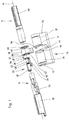
- the single FIGURE shows a lock cylinder 10 for a not-shown mortise lock for a door.
- the lock cylinder 10 has a housing 54 and a shaft 14 rotatably mounted in a longitudinal bore 12 of the housing 54.
- the longitudinal bore 12 is aligned in the longitudinal direction of the housing 54.
- the lock cylinder 10 further includes a locking nose 18 rotatable relative to the housing 54 about an axis of rotation 16 defined by the shaft 14.
- the locking nose 18 serves conventionally for driving a bolt and / or a latch of a lock, not shown, for opening or closing the door.
- the lock cylinder 10 comprises an actuatable by means of a drive 20 clutch 22, by means of which a coupling between the shaft 14 and the locking lug 18 can be produced in dependence on the verification of an authorization code.
- the verification of the authorization code is realized by means of an electronic circuit not shown in detail, which controls the drive 20 accordingly.
- the lock cylinder 10 is thus part of an electronic lock or an electronic locking system.
- the housing 54 is further divided by a recess 36 into two sections 32, 34.
- rotatable locking lug 18 is arranged in the recess 36 relative to the housing 54 .
- the longitudinal bore 12 is divided into two non-designated sections. In each case a portion of the longitudinal bore 12 is located in one of the housing sections 32, 34th
- the locking lug 18 also has a bore 42, so that in the assembled state of the lock cylinder 10, the shaft 14 not only the longitudinal bore 12, but also the bore 42 of the locking lug 18 can protrude. In the assembled state, the bore 42 in the lock cylinder 10 is arranged coaxially to the longitudinal bore 12.
- the drive 20 is formed by an electric motor 62, which is designed as a rotating electric machine.
- the electronic circuit that verifies the authorization code is designed for wireless entry of the authorization code.
- the authorization code is transmitted from a suitable electronic key via radio to the electronic circuit, the electronic circuit verifies the authorization code and drives the drive 20 accordingly with positive verification of the authorization code, so that the clutch 22 is actuated and by means of the shaft 14, the locking lug 18 can be actuated in the desired manner.
- the shaft 14 has at both ends of the shaft 14 each have a rotary knob, with which the shaft 14 is manually actuated.
- rotary knobs omitted and instead rotary drives are provided which allow automatic actuation of the shaft 14.
- the shaft 14 has two mutually rotatable sections 28, 30, wherein a first portion 28 of the sections rotatably connected to the locking lug 18 and in the uncoupled state against a second portion 30 of the shaft portion 14 is freely rotatable.
- This allows that with the first Section 28, the locking lug 18 can be operated independently of the coupling state of the clutch 22. This is advantageous for example for entrance doors, which should always be able to be operated from the inside usually.
- the second portion 30 is arranged on the outside, so that actuation is only possible if a valid authorization recognized and the clutch 22 is then actuated.
- the clutch 22 comprises a rotatably connected to the shaft 14, by the drive 20 parallel to the axis of rotation 16 movable slider 24.
- the slider 24 is mounted axially displaceable in a substantially parallel to the axis of rotation 16 recess of the second portion 30 of the shaft 14.
- the slider 24 is connected via a spring element 26 to the drive 20.
- the spring element 26 is formed in this embodiment by a spring pin.
- the second portion 30 of the shaft 14 has a cavity 56 in which the drive 20, the slider 24 and the spring element 26 are arranged.
- the slider 24 engages in the locking lug 18 a coupling.
- the slide 24 has a driver 50, which engages in the coupling state in a corresponding recess 52 of the locking lug 18.
- the driver 50 and the recess 52 are disengaged, so that the locking lug 18 and the second portion 30 of the shaft 14 can move freely relative to each other.
- the electric motor 62 has a motor shaft 58 protruding from the electric motor 62, which is coupled via an unillustrated worm wheel with a threaded sleeve 60 with an internal thread, not shown, whose internal thread meshes with the thread of the worm wheel.
- the motor shaft 58 and the threaded sleeve 60 are aligned coaxially with one another and axially parallel to the axis of rotation 16.
- the threaded sleeve 60 has a radial bore 64 into which the spring pin 26 is inserted, so that the spring pin 26 projects through the threaded sleeve 60 radially.
- one end of the spring pin 26 is fixedly connected to the slide 24.
- the threaded sleeve 60 is secured against rotation. A rotation of the motor shaft 58 thus leads to an axial displacement of the threaded sleeve 60 relative to the second portion 30 of the shaft 14th
- a displacement of the threaded sleeve 60 acts at the same time on the spring element 26, so that either a bias on the slider 24 in the coupling or in the non-coupling position is possible. As far as the slider 24 is axially free to move, this will follow the movement of the threaded sleeve 60.
- the clutch 22 comprises, in addition to the driver 50 of the slider 24 and the spring element 26, the recess 52 of the locking lug 18.
- the spring element 26 can be driven with the drive 20 in such a way that the driver 50 of the slider 24 moves in the direction of the recess 52 of the locking lug 18 is biased in the coupling state.
- the spring element 26 thus serves to store drive energy.
- the driver 50 engages in the corresponding recess 52 of the locking lug 18.
- the driver 50 and the recess 52 are in the production of the desired state of the coupling, the driver 50 and the recess 52 is not arranged cursing against each other, it can be achieved by manually rotating the second portion 30 of the shaft 14 relative to the housing 54, that the aligned state is achieved and by the bias of the spring element 26th the slide 24 automatically engages with its driver 50 in the recess 52 of the locking lug 18 and thus produces the coupling state.
- the drive 20 need not be activated in this case.
- the locking lug 18 can be actuated in a desired manner, so that the lock releases the door for opening.
- the drive 20 is driven accordingly.
- the bias voltage is reduced to the spring element 26 or vice versa, so that on the slider 24, a tensile force is applied.
- Characterized the slider 24 is moved away from the locking lug 18, wherein the driver 50 of the slider 24 is moved out of the recess 52 of the locking lug 18, so that the locking lug 18 against the second portion 30 of the shaft 14 is free to move again.
- the locking lug 18 has a projection 38, which is circumferentially annular in the present case.
- the projection 38 protrudes into the longitudinal bore 12 in the mounted state of the lock cylinder 10.
- the recess 36 has for this purpose on its front side 44 a circumferential recess 46, which also with the longitudinal bore 12 may be integrally formed.
- a spacer 40 is arranged in the recess 36.
- the spacer 40 prevents that in the partially assembled state, in which the locking lug 18 is already arranged on the housing 54 but the shaft 14 is not yet mounted, the locking lug 18 from its connection with the housing 54 can solve again. So that an assembly of the locking lug 18 in the recess 36 is possible, it must have a clear width, which is greater than the axial dimension of the locking lug 18 together with its projection 38.
- Engages in the assembled state of the locking lug 18 on the housing 54 of the projection 38 in the circumferential recess 46 arises on the opposite side of a free space that would allow the locking lug 18 to be released from their connection to the housing 54 again. This is prevented by the spacer 40.
- the spacer 40 After insertion of a displacement of the locking lug 18 in the axial direction with respect to the axis of rotation 16 is substantially reduced so far that the projection 38 is in constant attack with the circumferential recess 46.
- the closing lug 18 is rotatably connected to the housing 54.
- the locking lug 18 is thereby in the recess 36 regardless of its rotational position relative to the housing 54 in the axial direction set such that a rotation of the locking lug 18 relative to the housing 54 about the axis of rotation 16 is possible.
- the spacer 40 is presently designed as a plastic stamped part and has an opening 48, which allows that in the assembled state of the lock cylinder 10, the shaft 14, the lock cylinder 10 not only in the longitudinal bore 12, but also in the locking lug 18 and the spacer 40 completely can penetrate.
- the embodiment is merely illustrative of the invention and is not limitative of it.
- the locking lug 18 has a corresponding recess.
Landscapes
- Physics & Mathematics (AREA)
- Electromagnetism (AREA)
- Engineering & Computer Science (AREA)
- Mechanical Engineering (AREA)
- Lock And Its Accessories (AREA)
Description
- Die vorliegende Erfindung betrifft einen Schließzylinder für ein Schloss, insbesondere für ein Einsteckschloss für eine Tür, mit einem Gehäuse und einer in Längsrichtung des Gehäuses ausgerichteten Bohrung zur Aufnahme einer Welle und mit einer das Gehäuse in zwei Abschnitte aufteilenden Ausnehmung, in welcher Ausnehmung eine gegenüber dem Gehäuse verdrehbare Schließnase angeordnet ist. Weiterhin betrifft die Erfindung einen Schließzylinder für ein Schloss, insbesondere für ein Einsteckschloss für eine Tür, mit einem Gehäuse und einer in einer Längsbohrung des Gehäuses drehbar gelagerten Welle, mit einer gegenüber dem Gehäuse um eine, durch die Welle definierte Drehachse verdrehbaren Schließnase und mit einer mittels eines Antriebs betätigbaren Kupplung, mittels der in Abhängigkeit der Verifikation eines Berechtigungscodes eine drehfeste Kopplung zwischen der Welle und der Schließnase herstellbar ist.
- Schlösser mit gattungsgemäßen Schließzylindern sind aus dem Stand der Technik dem Grunde nach bekannt, und zwar sowohl in der Ausgestaltung als rein mechanisch arbeitendes Schloss als auch in der Ausgestaltung als elektronisch arbeitendes Schloss oder Kombinationen hiervon, so dass es eines gesonderten druckschriftlichen Nachweises an dieser Stelle nicht bedarf. Schlösser mit gattungsgemäßen Schließzylindern werden unter anderem im Eingangstürbereich in Türblätter eingesetzt, wobei über eine Welle des Schließzylinders das Öffnen und Schließen der Tür, das heißt, das Bewegen einer Falle und/oder eines Riegels ausgeführt wird. Zu diesem Zweck weist die Welle auf einer Türaußenseite eine Handhabe, insbesondere einen frei drehbaren Drehknauf auf, der nur dann eine Betätigung der Falle beziehungsweise des Riegels erlaubt, wenn zuvor durch den Schließzylinder ein Berechtigungscode verifiziert worden ist. Türinnenseitig ist ebenfalls eine Handhabe angeordnet, deren Betätigung unabhängig vom Vorliegen der Verifikation eines Berechtigungscodes die Betätigung der Falle beziehungsweise des Riegels ermöglicht. Dadurch kann gewährleistet werden, dass die Tür von der Innenseite her immer geöffnet werden kann, und zwar unabhängig vom Vorhandensein eines gültigen Berechtigungscodes. Der Berechtigungscode kann mechanisch oder elektronisch eingegeben werden. Beispielsweise ist er das Schließgeheimnis eines herkömmlichen mechanischen oder elektronischen Schlüssels. Der Berechtigungscode kann bei elektronischen Schlössern beispielsweise drahtlos über Funk, über eine Eingabetastatur oder dergleichen eingegeben werden. Solche Schlösser sind z.B. aus der
DE 10 2004 056 988 A1 oder aus derEP 0 588 209 A1 bekannt. - Aus der
DE 102 25 490 A1 ist eine Konstruktion für einen Schließzylinder bekannt, bei der die Welle des Schließzylinders in zwei Abschnitte unterteilt ist und über einen ersten und einen zweiten Abschnitt verfügt. Die beiden Abschnitte der Welle können mittels einer Kupplung in Wirkverbindung miteinander gebracht werden. Dabei ist die Kupplung zwischen zwei koaxial ineinander angeordneten Teilen des ersten Abschnitts der Welle angeordnet und verfügt über zwei in Ausnehmungen des zweiten Teils des ersten Abschnitts der Welle geführte Rollkörper, die zur Herstellung der Wirkverbindung zwischen dem ersten Teil und dem zweiten Teil des ersten Abschnitts der Welle mittels eines bewegbaren Schiebers in Umfangsrichtung des ersten Teils des ersten Abschnitts der Welle verlaufende Ausnehmungen einschiebbar sind. Der Schieber wird mittels eines Antriebs betätigt. - Weiterhin offenbart die
DE 20 2008 013 172 U1 einen gattungsgemäßen Schließzylinder, der es sich zur Aufgabe gemacht hat, ein Schloss, wie es aus derDE 102 25 490 A1 bekannt ist, hinsichtlich der Montage zu verbessern. Bei dieser Konstruktion ist der Antrieb zum Betätigen der Kupplung in der Welle angeordnet. Die Welle weist einen Wellenzapfen auf, der in eine Bohrung der Schließnase eingreift. Der Wellenzapfen umfasst einen mittels des Antriebs radial bewegbaren Stift, der in einer Bohrung des Wellenzapfens geführt ist. Im gekuppelten Zustand ist der Stift radial nach außen verfahren und greift zum Zwecke des Kuppelns in eine Ausnehmung in der Wand der Bohrung der Schließnase ein. - Auch wenn sich diese Konstruktion bewährt hat, besteht weiterhin Verbesserungsbedarf, da sich die vorgenannte Konstruktion immer noch als vergleichsweise aufwändig hinsichtlich der Montage herausgestellt hat.
- Es ist die Aufgabe der Erfindung, bei hoher Reaktionsgeschwindigkeit und geringem Energieverbrauch die Herstellkosten des Schließzylinders zu reduzieren und die Zuverlässigkeit des Schließzylinders zu verbessern. Insbesondere soll die Montage eines gattungsgemäßen Schließzylinders weiter vereinfacht werden.
- Als Lösung schlägt die Erfindung einen Schließzylinder für ein Schloss, insbesondere für ein Einsteckschloss für eine Tür, mit einem Gehäuse und einer in einer Längsbohrung des Gehäuses drehbar gelagerten Welle, mit einer gegenüber dem Gehäuse um eine durch die Welle definierte Drehachse verdrehbaren Schließnase und mit einer mittels eines Antriebs betätigbaren Kupplung vor, mittels der in Abhängigkeit der Verifikation eines Berechtigungscodes eine drehfeste Kopplung zwischen der Welle und der Schließnase herstellbar ist, wobei die Kupplung einen mit der Welle drehfest verbundenen, durch den als rotierende elektrische Maschine ausgebildeten Antrieb axial zur Welle bewegbaren Schieber umfasst, welcher Schieber über einen Kraftspeicher, insbesondere ein Federelement mit dem Antrieb verbunden ist und der im gekuppelten Zustand der Kupplung in die Schließnase kuppelnd eingreift, wobei der Kraftspeicher die durch den Antrieb für einen Kupplungsvorgang und für einen Entkupplungsvorgang bereit gestellte Energie zwischenspeichert und den Schieber beim Kupplungs- und Entkupplungsvorgang antreibt.
- Die Erfindung ermöglicht es, bei einer Kupplung, die vorzugsweise eine direkte Kopplung zwischen der Welle und der Schließnase ermöglicht, die Anzahl erforderlicher Bauelemente zu reduzieren. Kosten wie Bauteilekosten, Montageaufwand und dergleichen können dadurch reduziert werden. Dadurch, dass anstelle einer aufwändigen Kupplungsbaugruppe beim Stand der Technik gemäß der Erfindung lediglich ein Schieber und ein Kraftspeicher vorgesehen sind, kann die Anzahl der zu montierenden Teile deutlich reduziert werden. Dies reduziert nicht nur Kosten, sondern es vereinfacht den Aufbau des Schließzylinders und erhöht darüber hinaus die Zuverlässigkeit des Schließzylinders beziehungsweise des Schlosses. Aufwändige Konstruktionen zur Kraftumlenkung, um die Kupplung mechanisch zu realisieren, können vermieden werden. So ist es bei der Erfindung lediglich erforderlich, den Schieber vorzusehen, der in eine entsprechende Ausnehmung der Schließnase eingreifen kann.
- Dabei erweist es sich als vorteilhaft, dass der Schieber unter Vermittlung des Kraftspeichers angetrieben werden kann. Hierdurch ist es möglich, die durch den Antrieb für einen Kupplungsvorgang beziehungsweise für einen Entkupplungsvorgang bereitgestellte Energie zwischenzuspeichern, bis der Kupplungsvorgang beziehungsweise der Entkupplungsvorgang tatsächlich ausgeführt werden kann. Insbesondere wenn für den Kupplungsvorgang beziehungsweise den Entkupplungsvorgang eine relative Vorzugsstellung zwischen der Schließnase und der Welle erforderlich ist, kann die Energie für die Betätigung der Kupplung im Kraftspeicher bis zur Erreichung dieser Vorzugsstellung gespeichert werden. Die Vorzugsstellung kann durch eine oder mehrere relative Verdrehstellungen gebildet sein. Der Antrieb braucht deshalb nicht bis zur Ausführung des tatsächlichen Vorgangs des Kuppeln beziehungsweise des Entkuppeln aktiviert zu bleiben. Diese Art des Antriebs ermöglicht somit einen sehr geringen Energieverbrauch. Besonders vorteilhaft erweist sich die Erfindung bei elektronischen Schlössern, die durch eine Batterie mit elektrischer Energie versorgt werden. Der erfindungsgemäße Schließzylinder ermöglicht eine lange Betriebsdauer des elektronischen Schlosses ohne Batteriewechsel. Weiterhin erweist es sich als vorteilhaft, dass nur wenige Bauelemente zum Kuppeln beziehungsweise Entkuppeln betätigt werden müssen. Eine weitere Reduktion des Energieverbrauchs kann erreicht werden. Durch die geringe Anzahl der Bauelemente erhöht sich zugleich auch die Zuverlässigkeit des Schließzylinders. Der Kraftspeicher kann durch ein Federelement gebildet sein.
- Der Schieber und/oder der Kraftspeicher sind vorzugsweise an der Welle angeordnet. Besonders vorteilhaft lässt sich diese Anordnung auch mit der Anordnung des Antriebs an der Welle kombinieren. Natürlich kann auch eine Anordnung an anderer Stelle, beispielsweise im Gehäuse des Schließzylinders vorgesehen sein.
- Besonders vorteilhaft erweist es sich, wenn der Schieber im Wesentlichen axial zur Welle bewegbar ist. Dadurch kann dessen Funktion insbesondere bei Anordnung an der Welle von einer Rotationsbewegung der Welle entkoppelt werden, weil der Kupplungszustand nur durch eine Axialverschiebung des Schiebers erreicht werden kann. Bei der Konstruktion der
DE 20 2008 013 172 U1 kann dagegen aufgrund von Beschleunigungsbewegungen beim Drehen der Welle unter Umständen ungewollt ein Kupplungseffekt erreicht werden. Dieses Problem wird bei der erfindungsgemäßen Ausgestaltung vollständig vermieden. Der Schieber kann an der Welle axial geführt sein, so dass es auf Beschleunigungen aufgrund von Rotation der Welle bezüglich seiner Funktion nicht ankommt. - Der Schieber kann durch den Kraftspeicher mit einer Kraft beaufschlagt werden, so dass er im Falle des Erreichens einer vorgebbaren Verdrehstellung der Welle gegenüber der Schließnase in diese automatisch eingreifen kann, um den gekuppelten Zustand herzustellen. Hierdurch wird eine Funktion eines Einrastens realisiert. Vorzugsweise ist das Einrasten nur in einer oder mehreren ausgewählten relativen Verdrehstellungen beziehungsweise Verdrehpositionen der Welle gegenüber der Schließnase möglich. Dies erlaubt es, dass ein Kupplungszustand dann sehr schnell automatisch eingenommen werden kann, wenn der Schieber beziehungsweise die Welle und die Schließnase in einer verrastbaren Verdrehstellung gegenüber einander angeordnet sind. Einer erneuten Betätigung des Antriebs bedarf es nicht, weil die zum Herstellen des Kupplungszustands und des Entkupplungszustands erforderliche Energie durch den Kraftspeicher bereitgestellt werden kann. Dieser hat die Energie zuvor vom Antrieb erhalten und gespeichert.
- Um ein derartiges Einrasten bei einem Antrieb mittels eines Elektromotors in Form einer rotierenden elektrischen Maschine erreichen zu können, ist vorgesehen, dass der Schieber über ein Federelement mit dem Antrieb verbunden ist. Das Federelement kann beispielsweise eine Blattfeder, eine Spiralfeder, eine Tellerfeder oder dergleichen sein. Diese spannt den Schieber in dem Fall vor, dass der Berechtigungscode verifiziert worden ist und ein gekuppelter Zustand hergestellt werden soll. Der Antrieb wird entsprechend betätigt, wobei der Schieber aufgrund der relativen Verdrehstellung der Welle gegenüber der Schließnase noch nicht die kuppelnde Stellung einnehmen kann. Erst durch beispielsweise manuelles Verdrehen der Welle gegenüber der Schließnase schnappt der Schieber bei Erreichen der vorgegebenen Verdrehstellung in die kuppelnde Stellung automatisch ein, sobald die entsprechende relative Verdrehstellung der Welle gegenüber der Schließnase zum Einnehmen des kuppelnden Zustands erreicht ist. Die hierfür erforderliche Energie wird in dem Federelement als Kraftspeicher zwischengespeichert.
- Als Antrieb für die Kupplung ist ein elektrischer Antrieb vorgesehen, so dass ein elektronisches Schloss realisiert werden kann.
- Eine weitere Ausgestaltung der Erfindung sieht vor, dass die Welle zwei gegeneinander verdrehbare Abschnitte aufweist, wobei ein erster der Abschnitte drehfest mit der Schließnase verbunden und der Schieber an einem zweiten der Abschnitte der Welle angeordnet ist. Die beiden Abschnitte der Welle sind vorzugsweise dem Grunde frei gegeneinander verdrehbar, solange kein gekuppelter Zustand vorliegt. Diese Ausgestaltung eignet sich insbesondere für Türschlösser, bei denen eine Betätigung des Schlosses von beiden Seiten der Tür vorgesehen ist, wobei eine permanente Betätigungsmöglichkeit unabhängig vom Vorliegen eines Berechtigungscodes von einer Seite, die beispielsweise eine Türinnenseite ist, vorgesehen ist. Die Schließnase kann mit dem ersten Abschnitt auch einstückig ausgebildet sein. Erst im gekuppelten Zustand kann durch Kuppeln des zweiten Abschnitts der Welle mit der Schließnase zugleich ein Kuppeln der beiden Wellenabschnitte miteinander erreicht werden. Darüber hinaus kann aber auch - vorgesehen sein, dass der erste Abschnitt der Welle von der Schließnase derart entkoppelt ist, dass im gekuppelten Zustand der zweite Abschnitt der Welle lediglich die Schließnase kuppelt und die Schließnase zugleich von dem ersten Abschnitt der Welle entkuppelt. Unterschiedliche Gestaltungsmöglichkeiten sind je nach Funktionsbedarf realisierbar.
- Insbesondere kann vorgesehen sein, dass die Welle den Schließzylinder und die Schließnase durchgreift und an beiden Enden mit einer Handhabe versehen ist. Auf diese Weise kann erreicht werden, dass in beiden Betätigungsrichtungen der Tür das Vorliegen eines gültigen Berechtigungscodes erforderlich ist.
- In einem Ausführungsbeispiel ist das Gehäuse mit einer das Gehäuse in zwei Abschnitte aufteilenden Ausnehmung ausgebildet, in welcher Ausnehmung eine gegenüber dem Gehäuse verdrehbare Schließnase angeordnet ist, wobei die Schließnase einen Vorsprung aufweist, der in die Bohrung ragt, und wobei in der Ausnehmung benachbart zur Schließnase dem Vorsprung gegenüberliegend ein Distanzelement angeordnet ist, mittels welchem Vorsprung die Schließnase in der Ausnehmung unabhängig von ihrer Verdrehstellung gegenüber dem Gehäuse in Axialrichtung der Bohrung festgelegt ist.
- Im Unterschied zur Konstruktion der
DE 20 2008 013 172 U1 ist es bei diesem Ausführungsbeispiel nicht mehr erforderlich, dass während der Montage des Schließzylinders die Welle und die Schließnase zugleich und gemeinsam am Schließzylinder montiert werden müssen. Dies ergibt sich dadurch, dass es bei der Erfindung nicht mehr erforderlich ist, dass die Welle die Schließnase durchgreifen muss. Optional kann natürlich vorgesehen sein, dass im montierten Zustand die Welle auch die Schließnase durchgreift. Insbesondere erweist es sich als vorteilhaft, dass die Bauteile Schließnase und Welle bei der Montage des Schließzylinders getrennt voneinander im Schließzylinder angeordnet werden können. Hierdurch erweitert sich auch der Konstruktionsbereich, weil beispielsweise die Schließnase auch an einem Ende des Schließzylinders angeordnet sein kann. - Diese Ausgestaltung ermöglicht es, die Montage des Schließzylinders weiter zu vereinfachen. So kann die Schließnase am Schließzylinder montiert werden, ohne dass es erforderlich ist, dass die Schließnase gegenüber dem Schließzylinder durch gleichzeitiges Einführen der Welle fixiert wird. Die Montageschritte lassen sich auf diese Weise voneinander entkoppeln. Vorzugsweise weist die Schließnase einen Vorsprung in axialer Richtung der Bohrung beziehungsweise Längsbohrung auf, so dass auf eine einfache Weise eine Fixierung der Schließnase an einer schließnasenseitigen Stirnseite der Bohrung beziehungsweise Längsbohrung des Schließzylinders möglich ist. Besonders vorteilhaft können mehrere Vorsprünge vorgesehen sein, so dass zugleich eine Zentrierung der Schließnase gegenüber dem Schließzylinder erreicht werden kann. Um insbesondere bei mehreren Vorsprüngen eine einfache Montage erreichen zu können, ist vorzugsweise für die Ausnehmung des Gehäuses eine mindestens um die axialen Abmessungen des Vorsprungs in der Bohrung beziehungsweise Längsbohrung hinausgehende lichte Weite vorzusehen. Dadurch kann die Schließnase mit einem einfachen Montageschritt am Schließzylinder montiert werden.
- Es können mehrere Vorsprünge an der Schließnase vorgesehen sein. Der Vorsprung kann auch ringförmig ausgebildet sein. Besonders vorteilhaft ist der Vorsprung durch eine umlaufende Schulter gebildet. Dies erlaubt eine besonders einfache Montage und zugleich eine besonders zuverlässige Funktion. Durch die Schulter können zugleich große Kräfte beim Betätigen des Schlosses übertragen werden.
- Um die Schließnase in ihrer montierten Stellung gegenüber dem Schließzylinder zu halten, ist zusätzlich ein Distanzelement benachbart zur Schließnase dem Vorsprung gegenüberliegend angeordnet. Mit dem Distanzelement kann die Schließnase gegenüber dem Gehäuse in Axialrichtung der Bohrung festgelegt werden, sodass die Schließnase zwar durch das Gehäuse gehalten jedoch gegenüber dem Gehäuse verdreht werden kann. Das Distanzelement verhindert, dass die Schließnase sich aus ihrer Verbindungsstellung mit dem Schließzylinder wieder lösen kann. Das Distanzelement kann beispielsweise durch ein Metall- und/oder Kunststoffelement gebildet sein, welches in dem freien Raum zwischen Schließnase und Ausnehmung einsetzbar ist. Das Distanzelement kann beispielsweise durch Finger gebildet sein, die sich sowohl an einer Wand der Ausnehmung, als auch an der Schließnase abstützen.
- Weiterhin kann vorgesehen sein, dass die Schließnase eine Bohrung aufweist, die koaxial zur Bohrung des Gehäuses angeordnet ist. Dadurch ist es möglich, dass im montierten Zustand die Welle nicht nur die Bohrung beziehungsweise Längsbohrung des Gehäuses sondern auch die Schließnase selbst durchragt. Vorteilhaft ist dies beispielsweise, wenn die Betätigung der Tür das Vorliegen einer gültigen Berechtigung für beide Richtungen erfordert, weshalb eine einstückige Welle vorgesehen sein könnte. Aber auch die Kraftübertragung kann dadurch beim bestimmungsgemäßen Betrieb weiter verbessert werden.
- Weiterhin kann vorgesehen sein, dass eine dem Vorsprung der Schließnase zugewandte Stirnseite der Ausnehmung einen umlaufenden Absatz oder eine umlaufende Ausnehmung aufweist. Hierdurch kann der Vorsprung beziehungsweise die umlaufende Schulter aufgenommen werden, so dass die Bohrung des Gehäuses und eine Bohrung der Schließnase eine gemeinsame, fluchtende Bohrung für die Welle bilden können.
- Besonders vorteilhaft erweist es sich, wenn das Distanzelement scheibenförmig ausgebildet ist. Dadurch kann das Distanzelement im Wesentlichen gleichmäßig wirken, so dass ein Verkanten der Schließnase im Bereich der Ausnehmung weitgehend vermieden werden kann. Darüber hinaus lässt sich ein scheibenförmiges Distanzelement einfach herstellen.
- Eine Weiterbildung sieht der Erfindung vor, dass das Distanzelement eine Öffnung aufweist, in die die Welle einsetzbar ist. Dadurch kann das Distanzelement gleichzeitig gegenüber dem Schließzylinder fixiert werden. Weiterhin ermöglicht es diese Ausgestaltung, dass die Welle den Schließzylinder vollständig duchragen kann.
- Darüber hinaus kann das Distanzelement auch ein Federelement aufweisen, welches in die Bohrung eingreift. Das Federelement kann beispielsweise auf der Oberfläche der der Schließnase abgewandten Seite vorgesehen sein, damit das Distanzelement am Schließzylinder festgelegt werden kann. Das Federelement kann in die Bohrung beziehungsweise Längsbohrung des Gehäuses eingreifen. Dies erleichtert weiter die Montage. Das Federelement kann beispielsweise durch eine Federzunge, eine Rastnase oder dergleichen gebildet sein. Besonders vorteilhaft ist das Federelement einstückig mit dem Distanzelement ausgebildet.
- Mit der Erfindung wird ferner ein Schloss, insbesondere ein Einsteckschloss für eine Tür, mit einem Schließzylinder der Erfindung vorgeschlagen, wobei die Welle endseitig eine Handhabe, vorzugsweise einen Drehknauf oder eine Klinke trägt. Insbesondere kann vorgesehen sein, dass die Welle nicht nur an einem Ende, sondern an beiden Enden eine Handhabe trägt. Dies ermöglicht es, eine Vielzahl von Schlosskonstruktionen für die unterschiedlichsten Funktionsanforderungen an Türen zu realisieren. Das Schloss mit dem erfindungsgemäßen Schließzylinder lässt sich nicht nur einfach und kostengünstig herstellen, sondern es zeichnet auch durch eine hohe Zuverlässigkeit während des bestimmungsgemäßen Betriebs aus. Dies wird unter anderem dadurch erreicht, dass die Anzahl der beweglichen Teile reduziert ist.
- Weitere Vorteile und Merkmale sind der folgenden Beschreibung von Ausführungsbeispielen zu entnehmen. Das Ausführungsbeispiel dient lediglich der weiteren Erläuterung der Erfindung.
- Es zeigt die einzige Figur einen Schließzylinder gemäß der Erfindung in perspektivischer Explosionsdarstellung.
- Die einzige Figur zeigt einen Schließzylinder 10 für ein nicht näher dargestelltes Einsteckschloss für eine Tür. Der Schließzylinder 10 weist ein Gehäuse 54 und eine in einer Längsbohrung 12 des Gehäuses 54 drehbar gelagerten Welle 14 auf. Die Längsbohrung 12 ist in Längsrichtung des Gehäuses 54 ausgerichtet. Der Schließzylinder 10 umfasst ferner eine gegenüber dem Gehäuse 54 um eine durch die Welle 14 definierte Drehachse 16 verdrehbare Schließnase 18. Die Schließnase 18 dient in herkömmlicherweise zum Antrieb eines Riegels und/oder einer Falle eines nicht dargestellten Schlosses zum Öffnen beziehungsweise Verschließen der Tür.
- Ferner umfasst der Schließzylinder 10 eine mittels eines Antriebs 20 betätigbare Kupplung 22, mittels der in Abhängigkeit der Verifikation eines Berechtigungscodes eine Kopplung zwischen der Welle 14 und der Schließnase 18 herstellbar ist. Vorliegend ist die Verifikation des Berechtigungscodes mittels einer nicht näher dargestellten elektronischen Schaltung realisiert, die den Antrieb 20 entsprechend ansteuert. In dieser Ausgestaltung ist der Schließzylinder 10 somit Teil eines elektronischen Schlosses beziehungsweise einer elektronischen Schließanlage.
- Das Gehäuse 54 ist ferner durch eine Ausnehmung 36 in zwei Abschnitte 32, 34 aufgeteilt. In der Ausnehmung 36 ist die gegenüber dem Gehäuse 54 verdrehbare Schließnase 18 angeordnet. Entsprechend ist die Längsbohrung 12 in zwei nicht bezeichnete Abschnitte unterteilt. Jeweils ein Abschnitt der Längsbohrung 12 befindet sich in einem der Gehäuseabschnitte 32, 34.
- Die Schließnase 18 weist darüber hinaus eine Bohrung 42 auf, so dass im montierten Zustand des Schließzylinders 10 die Welle 14 nicht nur die Längsbohrung 12, sondern auch die Bohrung 42 der Schließnase 18 durchragen kann. Im montierten Zustand ist die Bohrung 42 im Schließzylinder 10 koaxial zur Längsbohrung 12 angeordnet.
- In der vorliegenden Ausgestaltung ist vorgesehen, dass der Antrieb 20 durch einen Elektromotor 62 gebildet ist, der als rotierende elektrische Maschine ausgebildet ist. Die elektronische Schaltung, die die Verifikation des Berechtigungscodes vornimmt, ist für eine drahtlose Eingabe des Berechtigungscodes ausgelegt. In dieser Ausgestaltung ist vorgesehen, dass der Berechtigungscode von einem geeigneten elektronischen Schlüssel über Funk an die elektronische Schaltung übermittelt wird, die elektronische Schaltung den Berechtigungscode verifiziert und bei positiver Verifikation des Berechtigungscodes den Antrieb 20 entsprechend ansteuert, so dass die Kupplung 22 betätigt wird und mittels der Welle 14 die Schließnase 18 in gewünschter Weise betätigt werden kann.
- Für die Betätigung der Welle 18 zum Öffnen beziehungsweise Schließen der Tür ist der Schließzylinder 10 Bestandteil des nicht dargestellten Schlosses. Die Welle 14 weist an beiden Enden der Welle 14 jeweils einen Drehknauf auf, mit dem die Welle 14 manuell betätigbar ist. Alternativ kann auch vorgesehen sein, dass einer oder beide Drehknäufe entfallen und stattdessen rotierende Antriebe vorgesehen sind, die ein automatisches Betätigen der Welle 14 ermöglichen.
- In dieser Ausgestaltung weist die Welle 14 zwei gegeneinander verdrehbare Abschnitte 28, 30 auf, wobei ein erster Abschnitt 28 der Abschnitte drehfest mit der Schließnase 18 verbunden und im nicht gekuppelten Zustand gegenüber einem zweiten Abschnitt 30 der der Abschnitte Welle 14 frei verdrehbar ist. Dies ermöglicht es, dass mit dem ersten Abschnitt 28 die Schließnase 18 unabhängig vom Kupplungszustand der Kupplung 22 betätigt werden kann. Vorteilhaft ist dies beispielsweise für Eingangstüren, die von der Innenseite in der Regel immer betätigt werden können sollen. Dagegen ist der zweite Abschnitt 30 außenseitig angeordnet, so dass eine Betätigung nur dann möglich ist, wenn eine gültige Berechtigung erkannt und die Kupplung 22 daraufhin betätigt wird.
- Die Kupplung 22 umfasst einen mit der Welle 14 drehfest verbundenen, durch den Antrieb 20 parallel zur Drehachse 16 bewegbaren Schieber 24. Der Schieber 24 ist in einer zur Drehachse 16 im Wesentlichen parallelen Ausnehmung des zweiten Abschnitts 30 der Welle 14 axial verschiebbar gelagert. Der Schieber 24 ist über ein Federelement 26 mit dem Antrieb 20 verbunden. Das Federelement 26 ist in dieser Ausgestaltung durch einen Federstift gebildet. Der zweite Abschnitt 30 der Welle 14 weist einen Hohlraum 56 auf, in welchem der Antrieb 20, der Schieber 24 sowie das Federelement 26 angeordnet sind.
- Im gekuppelten Zustand der Kupplung 22 greift der Schieber 24 in die Schließnase 18 kuppelnd ein. Dazu weist der Schieber 24 einen Mitnehmer 50 auf, der im kuppelnden Zustand in eine korrespondierende Ausnehmung 52 der Schließnase 18 eingreift. Im nicht kuppelnden Zustand sind der Mitnehmer 50 und die Ausnehmung 52 außer Eingriff, so dass sich die Schließnase 18 und der zweite Abschnitt 30 der Welle 14 frei gegenüber einander bewegen können.
- Zum Antrieb des Schiebers 24 weist der Elektromotor 62 eine aus dem Elektromotor 62 herausragende Motorwelle 58 auf, die über ein nicht dargestelltes Schneckenrad mit einer Gewindehülse 60 mit einem nicht dargestellten Innengewinde gekoppelt ist, deren Innengewinde mit dem Gewinde des Schneckenrades kämmt. Die Motorwelle 58 sowie die Gewindehülse 60 sind koaxial zueinander und achsparallel zur Drehachse 16 ausgerichtet.
- An einem dem Elektromotor 62 gegenüberliegenden Ende der Gewindehülse 60 weist die Gewindehülse 60 eine radiale Bohrung 64 auf, in die der Federstift 26 eingesetzt ist, so dass der Federstift 26 die Gewindehülse 60 radial durchragt. Zugleich ist ein Ende des Federstifts 26 mit dem Schieber 24 fest verbunden. Dadurch ist die Gewindehülse 60 gegen Verdrehen gesichert. Eine Rotation der Motorwelle 58 führt somit zu einer Axialverschiebung der Gewindehülse 60 gegenüber dem zweiten Abschnitt 30 der Welle 14.
- Eine Verschiebung der Gewindehülse 60 wirkt zugleich auf das Federelement 26 ein, so dass entweder eine Vorspannung auf den Schieber 24 in die kuppelnde oder auch in die nicht kuppelnde Stellung möglich ist. Soweit der Schieber 24 axial frei beweglich ist, wird dieser der Bewegung der Gewindehülse 60 folgen.
- Die Kupplung 22 umfasst neben dem Mitnehmer 50 des Schiebers 24 und dem Federelement 26 die Ausnehmung 52 der Schließnase 18. Mit dem Antrieb 20 kann im Falle des herzustellenden Kupplungszustands das Federelement 26 derart angetrieben werden, dass der Mitnehmer 50 des Schiebers 24 in Richtung der Ausnehmung 52 der Schließnase 18 in den kuppelnden Zustand vorgespannt ist. Das Federelement 26 dient somit zur Speicherung von Antriebsenergie. Im gekuppelten Zustand greift der Mitnehmer 50 in die entsprechende Ausnehmung 52 der Schließnase 18 ein. Sind beim Herstellen des gewünschten Kupplungszustands der Mitnehmer 50 und die Ausnehmung 52 nicht fluchend gegenübereinander angeordnet, so kann durch manuelles Verdrehen des zweiten Abschnitts 30 der Welle 14 gegenüber dem Gehäuse 54 erreicht werden, dass der fluchtende Zustand erreicht wird und durch die Vorspannung des Federelements 26 der Schieber 24 mit seinem Mitnehmer 50 in die Ausnehmung 52 der Schließnase 18 automatisch eingreift und somit den kuppelnden Zustand herstellt. Der Antrieb 20 braucht hierbei nicht weiter aktiviert zu sein. In diesem Zustand kann durch Betätigen des zweiten Abschnitts 30 der Welle 14 die Schließnase 18 in gewünschter Weise betätigt werden, so dass das Schloss die Tür zum Öffnen freigibt.
- Wird hingegen gewünscht, dass der kuppelnde Zustand beendet wird, so wird der Antrieb 20 entsprechend angesteuert. Mittels des Antriebs 20 wird die Vorspannung auf das Federelement 26 zurückgefahren beziehungsweise umgekehrt, so dass auf den Schieber 24 eine Zugkraft ausgeübt wird. Dadurch wird der Schieber 24 von der Schließnase 18 fortbewegt, wobei der Mitnehmer 50 des Schiebers 24 aus der Ausnehmung 52 der Schließnase 18 herausgefahren wird, so dass die Schließnase 18 gegenüber dem zweiten Abschnitt 30 der Welle 14 wieder frei beweglich ist. Mit wenigen robusten Bauelementen lässt sich folglich eine zuverlässige Kupplung realisieren.
- Weiterhin weist die Schließnase 18 einen Vorsprung 38 auf, der vorliegend umlaufend ringförmig ausgebildet ist. Der Vorsprung 38 ragt im montierten Zustand des Schließzylinders 10 in die Längsbohrung 12 hinein. Die Ausnehmung 36 weist hierfür an ihrer Stirnseite 44 eine umlaufende Ausnehmung 46 auf, die auch mit der Längsbohrung 12 einstückig ausgebildet sein kann.
- Aus der Figur ist ferner ersichtlich, dass dem Vorsprung 38 gegenüberliegend an der Schließnase 18 eine Distanzscheibe 40 in der Ausnehmung 36 angeordnet ist. Die Distanzscheibe 40 verhindert, dass sich im teilmontierten Zustand, bei dem die Schließnase 18 bereits am Gehäuse 54 angeordnet aber die Welle 14 noch nicht montiert ist, die Schließnase 18 aus ihrer Verbindung mit dem Gehäuse 54 wieder lösen kann. Damit nämlich eine Montage der Schließnase 18 in der Ausnehmung 36 möglich ist, muss diese eine lichte Weite haben, die größer ist, als die axiale Abmessung der Schließnase 18 zusammen mit ihrem Vorsprung 38. Greift im montierten Zustand der Schließnase 18 am Gehäuse 54 der Vorsprung 38 in die umlaufende Ausnehmung 46, entsteht auf der gegenüberliegenden Seite ein freier Raum, der es der Schließnase 18 erlauben würde, sich aus ihrer Verbindung mit dem Gehäuse 54 wieder zu lösen. Dies wird durch die Distanzscheibe 40 verhindert. Nach deren Einsetzen ist ein Verschieben der Schließnase 18 in axialer Richtung in Bezug zur Drehachse 16 im Wesentlichen soweit reduziert, dass der Vorsprung 38 in ständigem Angriff mit der umlaufenden Ausnehmung 46 ist. Dadurch ist die Schließnase 18 verdrehbar mit dem Gehäuse 54 verbunden. Die Schließnase 18 ist hierdurch in der Ausnehmung 36 unabhängig von ihrer Verdrehstellung gegenüber dem Gehäuse 54 in Axialrichtung derart festgelegt, dass ein Verdrehen der Schließnase 18 gegenüber dem Gehäuse 54 um die Drehachse 16 möglich ist.
- Die Distanzscheibe 40 ist vorliegend als Kunststoffstanzteil ausgebildet und weist eine Öffnung 48 auf, die es erlaubt, dass im montierten Zustand des Schließzylinders 10 die Welle 14 den Schließzylinder 10 nicht nur in der Längsbohrung 12, sondern auch in der Schließnase 18 sowie der Distanzscheibe 40 vollständig durchragen kann.
- Das Ausführungsbeispiel dient lediglich zur Erläuterung der Erfindung und ist für diese nicht beschränkend. Selbstverständlich kann natürlich vorgesehen sein, dass in einer dualen Ausgestaltung der Vorsprung nicht an der Schließnase, sondern stattdessen an der Stirnseite 44 angeordnet ist und korrespondierend hierzu die Schließnase 18 eine entsprechende Ausnehmung aufweist.
Bezugszeichen: 10 Schließzylinder 40 Distanzscheibe 12 Längsbohrung 42 Bohrung 14 Welle 44 Stirnseite 16 Drehachse 46 umlaufende Ausnehmung 18 Schließnase 48 Öffnung 20 Antrieb 50 Mitnehmer 22 Kupplung 52 Ausnehmung 24 Schieber 54 Gehäuse 26 Federelement 56 Hohlraum 28 erster Abschnitt 58 Motorwelle 30 zweiter Abschnitt 60 Gewindehülse 32 erster Abschnitt 62 Elektromotor 34 zweiter Abschnitt 64 Radialbohrung 36 Ausnehmung 38 Umlaufender ringförmiger Vorsprung
Claims (9)
- Schließzylinder (10) für ein Schloss, insbesondere für ein Einsteckschloss für eine Tür, mit einem Gehäuse (54) und einer in einer Längsbohrung (12) des Gehäuses (54) drehbar gelagerten Welle (14), mit einer gegenüber dem Gehäuse (54) um eine, durch die Welle (14) definierte Drehachse (16) verdrehbaren Schließnase (18) und mit einer mittels eines Antriebs (20) betätigbaren Kupplung (22), mittels der in Abhängigkeit der Verifikation eines Berechtigungscodes eine drehfeste Kopplung zwischen der Welle (14) und der Schließnase (18) herstellbar ist, wobei die Kupplung (22) einen mit der Welle (14) drehfest verbundenen, durch den als rotierende elektrische Maschine ausgebildeten Antrieb (20) axial zur Welle (14) bewegbaren Schieber (24) umfasst, welcher Schieber (24) über einen Kraftspeicher, insbesondere ein Federelement (26) mit dem Antrieb (20) verbunden ist und der im gekuppelten Zustand der Kupplung (22) in die Schließnase (18) kuppelnd eingreift, wobei der Kraftspeicher die durch den Antrieb (20) für einen Kupplungsvorgang und für einen Entkupplungsvorgang bereit gestellte Energie zwischenspeichert und den Schieber (24) beim Kupplungs- und Entkupplungsvorgang antreibt.
- Schließzylinder nach Anspruch 1, dadurch gekennzeichnet, dass die Welle (14) zwei gegeneinander verdrehbare Abschnitte (28, 30) aufweist, wobei ein erster der Abschnitte (28) drehfest mit der Schließnase (18) verbunden und der Schieber (24) an einem zweiten der Abschnitte (30) der Welle (14) angeordnet ist.
- Schließzylinder (10) nach Anspruch 1 oder 2, dadurch gekennzeichnet, dass das Gehäuse (54) mit einer das Gehäuse (54) in zwei Abschnitte (32, 34) aufteilenden Ausnehmung (36) ausgebildet ist, in welcher Ausnehmung (36) die gegenüber dem Gehäuse (54) verdrehbare Schließnase (18) angeordnet ist, wobei die Schließnase (18) einen Vorsprung (38) aufweist, der in die Längsbohrung (12) ragt, und wobei in der Ausnehmung (36) benachbart zur Schließnase (18) dem Vorsprung (38) gegenüberliegend ein Distanzelement (40) angeordnet ist, mittels welchem Vorsprung (38) die Schließnase (18) in der Ausnehmung (36) unabhängig von ihrer Verdrehstellung gegenüber dem Gehäuse (54) in Axialrichtung der Bohrung (12) festgelegt ist.
- Schließzylinder nach Anspruch 3, dadurch gekennzeichnet, dass der Vorsprung (38) durch eine umlaufende Schulter gebildet ist.
- Schließzylinder nach Anspruch 3 oder 4, dadurch gekennzeichnet, dass die Schließnase (18) eine Bohrung (42) aufweist, die koaxial zur Bohrung (12) des Gehäuses (54) angeordnet ist.
- Schließzylinder nach einem der Ansprüche 3 bis 5, dadurch gekennzeichnet, dass eine dem Vorsprung (38) der Schließnase (18) zugewandte Stirnseite (44) der Ausnehmung (36) einen umlaufenden Absatz (46) oder eine umlaufende Ausnehmung aufweist.
- Schließzylinder nach einem der Ansprüche 3 bis 6, dadurch gekennzeichnet, dass das Distanzelement (40) scheibenförmig ausgebildet ist.
- Schließzylinder nach einem der Ansprüche 3 bis 7, dadurch gekennzeichnet, dass das Distanzelement (40) eine Öffnung (48) aufweist, in die die Welle (14) einsetzbar ist.
- Schließzylinder nach einem der Ansprüche 3 bis 8, dadurch gekennzeichnet, dass das Distanzelement (40) ein Federelement aufweist, welches in die Bohrung (12) eingreift.
Applications Claiming Priority (1)
| Application Number | Priority Date | Filing Date | Title |
|---|---|---|---|
| DE202010013859 | 2010-10-01 |
Publications (3)
| Publication Number | Publication Date |
|---|---|
| EP2436858A2 EP2436858A2 (de) | 2012-04-04 |
| EP2436858A3 EP2436858A3 (de) | 2016-03-02 |
| EP2436858B1 true EP2436858B1 (de) | 2019-04-17 |
Family
ID=44759372
Family Applications (1)
| Application Number | Title | Priority Date | Filing Date |
|---|---|---|---|
| EP11007989.4A Active EP2436858B1 (de) | 2010-10-01 | 2011-09-30 | Schließzylinder für ein Schloss |
Country Status (2)
| Country | Link |
|---|---|
| EP (1) | EP2436858B1 (de) |
| DE (1) | DE202011106208U1 (de) |
Families Citing this family (14)
| Publication number | Priority date | Publication date | Assignee | Title |
|---|---|---|---|---|
| CN104963560B (zh) * | 2012-08-17 | 2017-09-26 | 东隆五金工业股份有限公司 | 一种电子锁的传动机构 |
| CN103711365B (zh) * | 2012-10-02 | 2016-01-20 | 盖恩斯伯勒硬件工业有限公司 | 锁组件及将装置在非可闭锁与钥匙可闭锁之间转换的方法 |
| DE102012020451A1 (de) | 2012-10-17 | 2014-04-17 | Dorma Gmbh + Co. Kg | System mit Türbetätigungsteil und Schließzylinder |
| DE102012020450A1 (de) | 2012-10-17 | 2014-04-17 | Dorma Gmbh + Co. Kg | Kupplungsmechanismus für ein Türbetätigungsteil |
| CN103174334A (zh) * | 2013-04-08 | 2013-06-26 | 湘潭市豪巍发展有限公司 | 一种离合式电子锁 |
| DE102013019662A1 (de) * | 2013-11-20 | 2015-05-21 | Assa Abloy Sicherheitstechnik Gmbh | Knaufzylinder |
| CN103670037B (zh) * | 2013-12-12 | 2016-01-20 | 江门市科裕智能科技有限公司 | 一种带隐藏机械锁芯的游离电子锁头 |
| CN106121383A (zh) * | 2016-08-30 | 2016-11-16 | 刘勇 | 电子锁及其智能锁芯 |
| CN106761002A (zh) * | 2016-12-30 | 2017-05-31 | 北京初创未来科技有限公司 | 一种智能锁 |
| CN107956327B (zh) * | 2017-10-25 | 2023-04-07 | 浙江浦江梅花锁业集团有限公司 | 一种锁芯 |
| WO2019237912A1 (zh) * | 2018-06-11 | 2019-12-19 | 武汉旭新通通信科技有限公司 | 一种具有空转特性的防非法开锁的电子锁芯及其控制方法和具有电子锁芯的系统 |
| WO2023114909A1 (en) | 2021-12-17 | 2023-06-22 | Spectrum Brands, Inc. | Electronic lock with mortise insert |
| US11655653B1 (en) | 2022-04-15 | 2023-05-23 | Digilock Asia Ltd. | Electronically operated lock cylinder |
| US12152409B2 (en) | 2022-04-15 | 2024-11-26 | Security People, Inc. | Electronic mortise lock cylinder |
Citations (11)
| Publication number | Priority date | Publication date | Assignee | Title |
|---|---|---|---|---|
| EP0413964A1 (de) | 1989-08-23 | 1991-02-27 | Gretsch Unitas GmbH Baubeschläge | Betätigungsvorrichtung für einen Riegel eines Schlosses |
| DE19831846A1 (de) | 1998-07-16 | 2000-01-20 | Winkhaus Fa August | Schließzylinder |
| DE19854454A1 (de) | 1998-11-13 | 2000-06-08 | Ulf Klenk | Schließzylinder |
| DE10225490A1 (de) | 2002-03-16 | 2003-10-09 | Burg Waechter Kg | Schloss |
| DE10235201A1 (de) | 2002-08-01 | 2004-02-19 | Günter Uhlmann | Türschließystem |
| DE102004056988A1 (de) | 2004-11-25 | 2006-06-01 | Keyowa Gmbh | Schließvorrichtung und Verfahren zum Betätigen einer Schließvorrichtung |
| DE102006020614A1 (de) | 2005-04-29 | 2006-11-02 | Mehmet Sancak | Schloss mit automatischer Rückstellung des Schließbarts |
| DE102006001266B3 (de) | 2006-01-10 | 2007-05-03 | Seccor High Security Gmbh | Motor und Koppeleinheit mitdrehend in der Achse elektronischer Schließzylinder |
| EP1953314A1 (de) | 2007-01-29 | 2008-08-06 | Günter Uhlmann | Elektromechanisches Schließsystem |
| DE102008001693B3 (de) | 2008-05-09 | 2009-12-10 | Uhlmann & Zacher Gmbh | Kupplung für ein elektromechanisches Schließsystem |
| WO2011022855A1 (de) | 2009-08-31 | 2011-03-03 | Kaba Ag | Schliesseinrichtung |
Family Cites Families (4)
| Publication number | Priority date | Publication date | Assignee | Title |
|---|---|---|---|---|
| IT1258149B (it) * | 1992-09-15 | 1996-02-20 | Italiana Serrature Affini | Serratura ad abilitazione elettrica |
| US8375753B2 (en) * | 2007-02-08 | 2013-02-19 | Knock N'lock Ltd. | Solenoid-operated electromechanical lock |
| ES2331865B1 (es) * | 2008-07-15 | 2010-10-28 | Salto Systems, S.L. | Mecanismo de embrague aplicable a cilindros electromecanicos de cerraduras. |
| DE202008013172U1 (de) | 2008-10-06 | 2010-02-25 | Burg-Wächter Kg | Schloss, insbesondere Einsteckschloss für eine Tür |
-
2011
- 2011-09-30 EP EP11007989.4A patent/EP2436858B1/de active Active
- 2011-09-30 DE DE202011106208U patent/DE202011106208U1/de not_active Expired - Lifetime
Patent Citations (11)
| Publication number | Priority date | Publication date | Assignee | Title |
|---|---|---|---|---|
| EP0413964A1 (de) | 1989-08-23 | 1991-02-27 | Gretsch Unitas GmbH Baubeschläge | Betätigungsvorrichtung für einen Riegel eines Schlosses |
| DE19831846A1 (de) | 1998-07-16 | 2000-01-20 | Winkhaus Fa August | Schließzylinder |
| DE19854454A1 (de) | 1998-11-13 | 2000-06-08 | Ulf Klenk | Schließzylinder |
| DE10225490A1 (de) | 2002-03-16 | 2003-10-09 | Burg Waechter Kg | Schloss |
| DE10235201A1 (de) | 2002-08-01 | 2004-02-19 | Günter Uhlmann | Türschließystem |
| DE102004056988A1 (de) | 2004-11-25 | 2006-06-01 | Keyowa Gmbh | Schließvorrichtung und Verfahren zum Betätigen einer Schließvorrichtung |
| DE102006020614A1 (de) | 2005-04-29 | 2006-11-02 | Mehmet Sancak | Schloss mit automatischer Rückstellung des Schließbarts |
| DE102006001266B3 (de) | 2006-01-10 | 2007-05-03 | Seccor High Security Gmbh | Motor und Koppeleinheit mitdrehend in der Achse elektronischer Schließzylinder |
| EP1953314A1 (de) | 2007-01-29 | 2008-08-06 | Günter Uhlmann | Elektromechanisches Schließsystem |
| DE102008001693B3 (de) | 2008-05-09 | 2009-12-10 | Uhlmann & Zacher Gmbh | Kupplung für ein elektromechanisches Schließsystem |
| WO2011022855A1 (de) | 2009-08-31 | 2011-03-03 | Kaba Ag | Schliesseinrichtung |
Non-Patent Citations (7)
| Title |
|---|
| ANONYMOUS: "Clex Prime CX6122 / CX6123", UHLMANN & ZACHER - GEBRAUCHSANWEISUNG, 14 March 2007 (2007-03-14), pages 1 - 4, XP055674074 |
| ANONYMOUS: "Feder (Technik)", WIKIPEDIA, 26 September 2010 (2010-09-26), XP055674044, Retrieved from the Internet <URL:https://de.wikipedia.org/w/index.php?title=Feder_(Technik)&oldid=79580908> |
| ANONYMOUS: "Passchreiben", WIKIPEDIA, 15 April 2010 (2010-04-15), XP055674053, Retrieved from the Internet <URL:https://de.wikipedia.org/w/index.php?title=Passscheib e&oldid=73168891> |
| ANONYMOUS: "Systembeschreibung Clex Prime", UHLMANN & ZACHER - KATALOG, 5 May 2004 (2004-05-05), pages 1 - 30, XP055674082 |
| BEITZ W. ET AL: "DUBBEL. Taschenbuch für Maschinenbau", 2001, SPRINGER, article "Federnde Verbindungen", pages: 50 - 59, 78-79, XP055674056 |
| HERBERT WITTEL ET AL.: "ROLOFF / MATEK MASCHINENELEMENTE", vol. 19, 2009, VIEWEG + TEUBNER |
| MEYERS: "Meyers Lexikon der Technik und der exakten Naturwis- senschaften", 1970, BIBLIOGRAPHISCHES INSTITUT AG, article "Passchreiben", pages: 1910, XP055674051 |
Also Published As
| Publication number | Publication date |
|---|---|
| DE202011106208U1 (de) | 2012-01-12 |
| EP2436858A3 (de) | 2016-03-02 |
| EP2436858A2 (de) | 2012-04-04 |
Similar Documents
| Publication | Publication Date | Title |
|---|---|---|
| EP2436858B1 (de) | Schließzylinder für ein Schloss | |
| EP1636454B1 (de) | Elektromechanischer schliesszylinder | |
| DE69417530T2 (de) | Gegen Einbruch widerstandsfähiges Zylinderschloss | |
| DE10320873B4 (de) | Bewegungsübertragungsvorrichtung und -verfahren | |
| EP1155427B1 (de) | Vorrichtung zur aufnahme und halterung eines identifikationsgebers, wie eines elektronischen schlüssels, insbesondere für einen züdanlassschalter | |
| EP0819810B1 (de) | Beschlag für ein Schloss | |
| DE102018202563B4 (de) | Knauf für einen elektronischen Schließzylinder | |
| EP1310618A2 (de) | Kupplungsmechanismus für Schliesssysteme | |
| EP1072741A1 (de) | Schliesszylinder | |
| WO2017021410A1 (de) | Betätigungselement für ein kastenschloss | |
| AT507583B1 (de) | Sperrvorrichtung | |
| DE102010018243A1 (de) | Schließzylinderanordnung | |
| DE102007011554B4 (de) | Koppeleinheit für elektronische Schließ-Systeme | |
| DE112007002578B4 (de) | Schließzylinder | |
| EP1736620A1 (de) | Schliesszylinder mit gesperrter Knaufwelle | |
| EP3535463B1 (de) | Schliesseinheit für ein kraftfahrzeug | |
| DE102005059384B4 (de) | Schloss | |
| EP4112856B1 (de) | Schloss mit einem von einem betätigungselement drehbaren riegel | |
| DE102011102140B4 (de) | Schließzylinder für ein Schloss | |
| EP4191000B1 (de) | Elektromechanische sperrvorrichtung | |
| EP4441317B1 (de) | Elektromechanische sperrvorrichtung | |
| EP4086414B1 (de) | Schliesszylinderanordnung mit knauf-kupplung | |
| EP2169152B1 (de) | Schlüssel mit einem ersten und einem zweiten Teil | |
| EP1960621B1 (de) | Elektrisches Schloss mit manueller Notfallbetätigung | |
| EP4509681A1 (de) | Zylinderschloss |
Legal Events
| Date | Code | Title | Description |
|---|---|---|---|
| PUAI | Public reference made under article 153(3) epc to a published international application that has entered the european phase |
Free format text: ORIGINAL CODE: 0009012 |
|
| AK | Designated contracting states |
Kind code of ref document: A2 Designated state(s): AL AT BE BG CH CY CZ DE DK EE ES FI FR GB GR HR HU IE IS IT LI LT LU LV MC MK MT NL NO PL PT RO RS SE SI SK SM TR |
|
| AX | Request for extension of the european patent |
Extension state: BA ME |
|
| RIC1 | Information provided on ipc code assigned before grant |
Ipc: E05B 47/00 20060101ALN20151008BHEP Ipc: E05B 17/04 20060101ALI20151008BHEP Ipc: E05B 47/06 20060101AFI20151008BHEP Ipc: E05B 9/04 20060101ALI20151008BHEP |
|
| PUAL | Search report despatched |
Free format text: ORIGINAL CODE: 0009013 |
|
| AK | Designated contracting states |
Kind code of ref document: A3 Designated state(s): AL AT BE BG CH CY CZ DE DK EE ES FI FR GB GR HR HU IE IS IT LI LT LU LV MC MK MT NL NO PL PT RO RS SE SI SK SM TR |
|
| AX | Request for extension of the european patent |
Extension state: BA ME |
|
| RIC1 | Information provided on ipc code assigned before grant |
Ipc: E05B 47/00 20060101ALN20160127BHEP Ipc: E05B 17/04 20060101ALI20160127BHEP Ipc: E05B 47/06 20060101AFI20160127BHEP Ipc: E05B 9/04 20060101ALI20160127BHEP |
|
| 17P | Request for examination filed |
Effective date: 20160614 |
|
| RBV | Designated contracting states (corrected) |
Designated state(s): AL AT BE BG CH CY CZ DE DK EE ES FI FR GB GR HR HU IE IS IT LI LT LU LV MC MK MT NL NO PL PT RO RS SE SI SK SM TR |
|
| STAA | Information on the status of an ep patent application or granted ep patent |
Free format text: STATUS: EXAMINATION IS IN PROGRESS |
|
| 17Q | First examination report despatched |
Effective date: 20180314 |
|
| GRAP | Despatch of communication of intention to grant a patent |
Free format text: ORIGINAL CODE: EPIDOSNIGR1 |
|
| STAA | Information on the status of an ep patent application or granted ep patent |
Free format text: STATUS: GRANT OF PATENT IS INTENDED |
|
| RIC1 | Information provided on ipc code assigned before grant |
Ipc: E05B 47/06 20060101AFI20181024BHEP Ipc: E05B 47/00 20060101ALN20181024BHEP Ipc: E05B 9/04 20060101ALI20181024BHEP Ipc: E05B 17/04 20060101ALI20181024BHEP |
|
| INTG | Intention to grant announced |
Effective date: 20181122 |
|
| GRAS | Grant fee paid |
Free format text: ORIGINAL CODE: EPIDOSNIGR3 |
|
| GRAA | (expected) grant |
Free format text: ORIGINAL CODE: 0009210 |
|
| STAA | Information on the status of an ep patent application or granted ep patent |
Free format text: STATUS: THE PATENT HAS BEEN GRANTED |
|
| AK | Designated contracting states |
Kind code of ref document: B1 Designated state(s): AL AT BE BG CH CY CZ DE DK EE ES FI FR GB GR HR HU IE IS IT LI LT LU LV MC MK MT NL NO PL PT RO RS SE SI SK SM TR |
|
| REG | Reference to a national code |
Ref country code: GB Ref legal event code: FG4D Free format text: NOT ENGLISH |
|
| REG | Reference to a national code |
Ref country code: CH Ref legal event code: EP |
|
| REG | Reference to a national code |
Ref country code: DE Ref legal event code: R096 Ref document number: 502011015597 Country of ref document: DE |
|
| REG | Reference to a national code |
Ref country code: AT Ref legal event code: REF Ref document number: 1121720 Country of ref document: AT Kind code of ref document: T Effective date: 20190515 Ref country code: IE Ref legal event code: FG4D Free format text: LANGUAGE OF EP DOCUMENT: GERMAN |
|
| REG | Reference to a national code |
Ref country code: NL Ref legal event code: MP Effective date: 20190417 |
|
| REG | Reference to a national code |
Ref country code: LT Ref legal event code: MG4D |
|
| PG25 | Lapsed in a contracting state [announced via postgrant information from national office to epo] |
Ref country code: NL Free format text: LAPSE BECAUSE OF FAILURE TO SUBMIT A TRANSLATION OF THE DESCRIPTION OR TO PAY THE FEE WITHIN THE PRESCRIBED TIME-LIMIT Effective date: 20190417 |
|
| PG25 | Lapsed in a contracting state [announced via postgrant information from national office to epo] |
Ref country code: SE Free format text: LAPSE BECAUSE OF FAILURE TO SUBMIT A TRANSLATION OF THE DESCRIPTION OR TO PAY THE FEE WITHIN THE PRESCRIBED TIME-LIMIT Effective date: 20190417 Ref country code: ES Free format text: LAPSE BECAUSE OF FAILURE TO SUBMIT A TRANSLATION OF THE DESCRIPTION OR TO PAY THE FEE WITHIN THE PRESCRIBED TIME-LIMIT Effective date: 20190417 Ref country code: PT Free format text: LAPSE BECAUSE OF FAILURE TO SUBMIT A TRANSLATION OF THE DESCRIPTION OR TO PAY THE FEE WITHIN THE PRESCRIBED TIME-LIMIT Effective date: 20190817 Ref country code: AL Free format text: LAPSE BECAUSE OF FAILURE TO SUBMIT A TRANSLATION OF THE DESCRIPTION OR TO PAY THE FEE WITHIN THE PRESCRIBED TIME-LIMIT Effective date: 20190417 Ref country code: LT Free format text: LAPSE BECAUSE OF FAILURE TO SUBMIT A TRANSLATION OF THE DESCRIPTION OR TO PAY THE FEE WITHIN THE PRESCRIBED TIME-LIMIT Effective date: 20190417 Ref country code: HR Free format text: LAPSE BECAUSE OF FAILURE TO SUBMIT A TRANSLATION OF THE DESCRIPTION OR TO PAY THE FEE WITHIN THE PRESCRIBED TIME-LIMIT Effective date: 20190417 Ref country code: NO Free format text: LAPSE BECAUSE OF FAILURE TO SUBMIT A TRANSLATION OF THE DESCRIPTION OR TO PAY THE FEE WITHIN THE PRESCRIBED TIME-LIMIT Effective date: 20190717 Ref country code: FI Free format text: LAPSE BECAUSE OF FAILURE TO SUBMIT A TRANSLATION OF THE DESCRIPTION OR TO PAY THE FEE WITHIN THE PRESCRIBED TIME-LIMIT Effective date: 20190417 |
|
| PG25 | Lapsed in a contracting state [announced via postgrant information from national office to epo] |
Ref country code: PL Free format text: LAPSE BECAUSE OF FAILURE TO SUBMIT A TRANSLATION OF THE DESCRIPTION OR TO PAY THE FEE WITHIN THE PRESCRIBED TIME-LIMIT Effective date: 20190417 Ref country code: LV Free format text: LAPSE BECAUSE OF FAILURE TO SUBMIT A TRANSLATION OF THE DESCRIPTION OR TO PAY THE FEE WITHIN THE PRESCRIBED TIME-LIMIT Effective date: 20190417 Ref country code: BG Free format text: LAPSE BECAUSE OF FAILURE TO SUBMIT A TRANSLATION OF THE DESCRIPTION OR TO PAY THE FEE WITHIN THE PRESCRIBED TIME-LIMIT Effective date: 20190717 Ref country code: RS Free format text: LAPSE BECAUSE OF FAILURE TO SUBMIT A TRANSLATION OF THE DESCRIPTION OR TO PAY THE FEE WITHIN THE PRESCRIBED TIME-LIMIT Effective date: 20190417 |
|
| PG25 | Lapsed in a contracting state [announced via postgrant information from national office to epo] |
Ref country code: IS Free format text: LAPSE BECAUSE OF FAILURE TO SUBMIT A TRANSLATION OF THE DESCRIPTION OR TO PAY THE FEE WITHIN THE PRESCRIBED TIME-LIMIT Effective date: 20190817 |
|
| REG | Reference to a national code |
Ref country code: DE Ref legal event code: R026 Ref document number: 502011015597 Country of ref document: DE |
|
| PLBI | Opposition filed |
Free format text: ORIGINAL CODE: 0009260 |
|
| PLAX | Notice of opposition and request to file observation + time limit sent |
Free format text: ORIGINAL CODE: EPIDOSNOBS2 |
|
| PG25 | Lapsed in a contracting state [announced via postgrant information from national office to epo] |
Ref country code: DK Free format text: LAPSE BECAUSE OF FAILURE TO SUBMIT A TRANSLATION OF THE DESCRIPTION OR TO PAY THE FEE WITHIN THE PRESCRIBED TIME-LIMIT Effective date: 20190417 Ref country code: SK Free format text: LAPSE BECAUSE OF FAILURE TO SUBMIT A TRANSLATION OF THE DESCRIPTION OR TO PAY THE FEE WITHIN THE PRESCRIBED TIME-LIMIT Effective date: 20190417 Ref country code: RO Free format text: LAPSE BECAUSE OF FAILURE TO SUBMIT A TRANSLATION OF THE DESCRIPTION OR TO PAY THE FEE WITHIN THE PRESCRIBED TIME-LIMIT Effective date: 20190417 Ref country code: CZ Free format text: LAPSE BECAUSE OF FAILURE TO SUBMIT A TRANSLATION OF THE DESCRIPTION OR TO PAY THE FEE WITHIN THE PRESCRIBED TIME-LIMIT Effective date: 20190417 Ref country code: EE Free format text: LAPSE BECAUSE OF FAILURE TO SUBMIT A TRANSLATION OF THE DESCRIPTION OR TO PAY THE FEE WITHIN THE PRESCRIBED TIME-LIMIT Effective date: 20190417 |
|
| 26 | Opposition filed |
Opponent name: UHLMANN & ZACHER GMBH Effective date: 20200117 |
|
| PG25 | Lapsed in a contracting state [announced via postgrant information from national office to epo] |
Ref country code: SM Free format text: LAPSE BECAUSE OF FAILURE TO SUBMIT A TRANSLATION OF THE DESCRIPTION OR TO PAY THE FEE WITHIN THE PRESCRIBED TIME-LIMIT Effective date: 20190417 Ref country code: IT Free format text: LAPSE BECAUSE OF FAILURE TO SUBMIT A TRANSLATION OF THE DESCRIPTION OR TO PAY THE FEE WITHIN THE PRESCRIBED TIME-LIMIT Effective date: 20190417 |
|
| PG25 | Lapsed in a contracting state [announced via postgrant information from national office to epo] |
Ref country code: TR Free format text: LAPSE BECAUSE OF FAILURE TO SUBMIT A TRANSLATION OF THE DESCRIPTION OR TO PAY THE FEE WITHIN THE PRESCRIBED TIME-LIMIT Effective date: 20190417 |
|
| PG25 | Lapsed in a contracting state [announced via postgrant information from national office to epo] |
Ref country code: SI Free format text: LAPSE BECAUSE OF FAILURE TO SUBMIT A TRANSLATION OF THE DESCRIPTION OR TO PAY THE FEE WITHIN THE PRESCRIBED TIME-LIMIT Effective date: 20190417 Ref country code: MC Free format text: LAPSE BECAUSE OF FAILURE TO SUBMIT A TRANSLATION OF THE DESCRIPTION OR TO PAY THE FEE WITHIN THE PRESCRIBED TIME-LIMIT Effective date: 20190417 |
|
| PLAF | Information modified related to communication of a notice of opposition and request to file observations + time limit |
Free format text: ORIGINAL CODE: EPIDOSCOBS2 |
|
| REG | Reference to a national code |
Ref country code: CH Ref legal event code: PL |
|
| PLBB | Reply of patent proprietor to notice(s) of opposition received |
Free format text: ORIGINAL CODE: EPIDOSNOBS3 |
|
| PG25 | Lapsed in a contracting state [announced via postgrant information from national office to epo] |
Ref country code: CH Free format text: LAPSE BECAUSE OF NON-PAYMENT OF DUE FEES Effective date: 20190930 Ref country code: LI Free format text: LAPSE BECAUSE OF NON-PAYMENT OF DUE FEES Effective date: 20190930 Ref country code: LU Free format text: LAPSE BECAUSE OF NON-PAYMENT OF DUE FEES Effective date: 20190930 Ref country code: IE Free format text: LAPSE BECAUSE OF NON-PAYMENT OF DUE FEES Effective date: 20190930 |
|
| REG | Reference to a national code |
Ref country code: BE Ref legal event code: MM Effective date: 20190930 |
|
| PG25 | Lapsed in a contracting state [announced via postgrant information from national office to epo] |
Ref country code: BE Free format text: LAPSE BECAUSE OF NON-PAYMENT OF DUE FEES Effective date: 20190930 |
|
| REG | Reference to a national code |
Ref country code: AT Ref legal event code: MM01 Ref document number: 1121720 Country of ref document: AT Kind code of ref document: T Effective date: 20190930 |
|
| PG25 | Lapsed in a contracting state [announced via postgrant information from national office to epo] |
Ref country code: AT Free format text: LAPSE BECAUSE OF NON-PAYMENT OF DUE FEES Effective date: 20190930 |
|
| PG25 | Lapsed in a contracting state [announced via postgrant information from national office to epo] |
Ref country code: CY Free format text: LAPSE BECAUSE OF FAILURE TO SUBMIT A TRANSLATION OF THE DESCRIPTION OR TO PAY THE FEE WITHIN THE PRESCRIBED TIME-LIMIT Effective date: 20190417 |
|
| PG25 | Lapsed in a contracting state [announced via postgrant information from national office to epo] |
Ref country code: GR Free format text: LAPSE BECAUSE OF FAILURE TO SUBMIT A TRANSLATION OF THE DESCRIPTION OR TO PAY THE FEE WITHIN THE PRESCRIBED TIME-LIMIT Effective date: 20190417 |
|
| PG25 | Lapsed in a contracting state [announced via postgrant information from national office to epo] |
Ref country code: MT Free format text: LAPSE BECAUSE OF FAILURE TO SUBMIT A TRANSLATION OF THE DESCRIPTION OR TO PAY THE FEE WITHIN THE PRESCRIBED TIME-LIMIT Effective date: 20190417 Ref country code: HU Free format text: LAPSE BECAUSE OF FAILURE TO SUBMIT A TRANSLATION OF THE DESCRIPTION OR TO PAY THE FEE WITHIN THE PRESCRIBED TIME-LIMIT; INVALID AB INITIO Effective date: 20110930 |
|
| REG | Reference to a national code |
Ref country code: DE Ref legal event code: R100 Ref document number: 502011015597 Country of ref document: DE |
|
| PLCK | Communication despatched that opposition was rejected |
Free format text: ORIGINAL CODE: EPIDOSNREJ1 |
|
| PLBN | Opposition rejected |
Free format text: ORIGINAL CODE: 0009273 |
|
| STAA | Information on the status of an ep patent application or granted ep patent |
Free format text: STATUS: OPPOSITION REJECTED |
|
| 27O | Opposition rejected |
Effective date: 20210927 |
|
| PG25 | Lapsed in a contracting state [announced via postgrant information from national office to epo] |
Ref country code: MK Free format text: LAPSE BECAUSE OF FAILURE TO SUBMIT A TRANSLATION OF THE DESCRIPTION OR TO PAY THE FEE WITHIN THE PRESCRIBED TIME-LIMIT Effective date: 20190417 |
|
| PGFP | Annual fee paid to national office [announced via postgrant information from national office to epo] |
Ref country code: FR Payment date: 20241002 Year of fee payment: 15 |
|
| REG | Reference to a national code |
Ref country code: DE Ref legal event code: R081 Ref document number: 502011015597 Country of ref document: DE Owner name: BURG-WAECHTER GMBH & CO. KG, DE Free format text: FORMER OWNER: BURG-WAECHTER KG, 58540 MEINERZHAGEN, DE |
|
| PGFP | Annual fee paid to national office [announced via postgrant information from national office to epo] |
Ref country code: DE Payment date: 20250930 Year of fee payment: 15 |
|
| PGFP | Annual fee paid to national office [announced via postgrant information from national office to epo] |
Ref country code: GB Payment date: 20250902 Year of fee payment: 15 |