EP2435284B1 - Schienenschaumstoffbalken - Google Patents
Schienenschaumstoffbalken Download PDFInfo
- Publication number
- EP2435284B1 EP2435284B1 EP10781279.4A EP10781279A EP2435284B1 EP 2435284 B1 EP2435284 B1 EP 2435284B1 EP 10781279 A EP10781279 A EP 10781279A EP 2435284 B1 EP2435284 B1 EP 2435284B1
- Authority
- EP
- European Patent Office
- Prior art keywords
- foam body
- rail
- applicator
- rubber foam
- elongate polymeric
- Prior art date
- Legal status (The legal status is an assumption and is not a legal conclusion. Google has not performed a legal analysis and makes no representation as to the accuracy of the status listed.)
- Active
Links
Images






Classifications
-
- B—PERFORMING OPERATIONS; TRANSPORTING
- B61—RAILWAYS
- B61K—AUXILIARY EQUIPMENT SPECIALLY ADAPTED FOR RAILWAYS, NOT OTHERWISE PROVIDED FOR
- B61K3/00—Wetting or lubricating rails or wheel flanges
-
- E—FIXED CONSTRUCTIONS
- E01—CONSTRUCTION OF ROADS, RAILWAYS, OR BRIDGES
- E01B—PERMANENT WAY; PERMANENT-WAY TOOLS; MACHINES FOR MAKING RAILWAYS OF ALL KINDS
- E01B7/00—Switches; Crossings
- E01B7/26—Lubricating of switches
Definitions
- the present invention relates to an apparatus for lubricating railroad rails or for applying friction modifiers to railroad rails.
- grease or friction modifier materials are applied onto railroad rails, such as to the top of rails or sides of the rails at curves, turnouts, switches, in some cases, the sections of the track immediately before a switch, and periodically spaced along the length of the track.
- Such lubricants and friction modifying materials can either reduce or increase the friction where necessary to improve train performance and reduce wear on both the rails and the train wheels.
- the practice has been to apply the friction modifier material to the top of the rail to contact the train wheels. Oftentimes, the friction modifying material does not reach the center of the rail or substantial amounts of friction modifying material are wasted by dripping or pouring to a position where the material is not needed.
- US6,971,479 discloses an applicator device comprising an applicator pad, such as a foam body, and a dispenser housing.
- the dispenser housing includes a flow chamber and a bottom distribution plate to which the applicator pad is affixed or otherwise attached.
- US2004/228672 discloses an application system for applying a friction modifying material to the top of railroad rails comprising an applicator bar with a D-shaped seal.
- the D-shaped seal sits on a front blade and a distribution blade, and has a plurality of holes through which friction modifying material flows.
- the applicator bar is configured so that the friction modifying material is distributed along the length within the applicator bar prior to exiting the applicator bar.
- WO2008/096109 discloses an applicator for distributing a friction modifying material on a gauge surface of a rail, wherein the friction modifying material is extruded from the applicator and the extruded column of the friction modifying material is contacted and spread along the rail by the passing wheel flanges.
- a rail applicator assembly in one embodiment, includes a rail having a head portion, a base portion, and a web portion extending between the head portion and the base portion. The head portion defines a field surface.
- the rail applicator assembly also includes an applicator for applying a friction modifying material to the field surface of the rail.
- the applicator includes an elongate polymeric or rubber foam body and an applicator support.
- the elongate polymeric or rubber foam body is secured to the applicator support and defines a flow passageway consisting of one conduit that extends through the elongate polymeric or rubber foam body for friction modifying material to flow through.
- the applicator is mounted against the field surface with a top surface of the elongate polymeric or rubber foam body inclined downwardly toward the field surface. The elongate polymeric or rubber foam body compresses when contacted by a passing rail wheel and then returns to its original form.
- the flow passageway may extend from a bottom surface to a top surface of the foam body with the top surface of the foam body defining an exit port of the flow passageway.
- the flow passageway may be angled towards a front surface of the foam body and the flow passageway may be wider at a top portion of the foam body than a lower portion of the foam body.
- the exit port of the flow passageway may be substantially slot-shaped.
- the flow passageway may also be substantially circular-shaped.
- the applicator support may include a generally C-shaped elongate body and may include a pair of extensions that extend from the generally C-shaped elongate body.
- a top surface of the foam body may include a rib generally extending in a longitudinal direction of the foam body. The rib may include at least one curved portion that extends towards the rail.
- a rail applicator in a further embodiment, includes an elongate polymeric or rubber foam body configured to apply friction modifying material to a field surface of a head portion of a rail.
- the elongate polymeric or rubber foam body defines a flow passageway consisting of one conduit that extends through the elongate polymeric or rubber foam body for friction modifying material to flow through.
- the applicator also includes an applicator support with the elongate polymeric or rubber foam body being secured to the applicator support. The elongate polymeric or rubber foam body compresses when contact by a passing rail wheel and then returns to its original form.
- a method of applying friction modifying material to a rail includes engaging a field surface of a head portion of a rail with an applicator.
- the applicator includes an elongate polymeric or rubber foam body and an applicator support.
- the elongate polymeric or rubber foam body is secured to the applicator support and defines a flow passageway consisting of one conduit that extends through the foam body.
- the method also includes applying friction modifying material to the field surface of the head portion of the rail by distributing the friction modifying material through the flow passageway and exiting the flow passageway via an exit port.
- the method may also include compressing the applicator such that the exit port is substantially closed prior to friction modifying material exiting through the exit port.
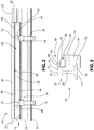
- the rail applicator assembly 10 includes a railroad rail 15 and an applicator 40 for applying a friction modifying material to the rail 15.
- the rail 15 includes a base portion 17 with flanges 19 extending therefrom and a head portion 21 having a web portion 23, which extends between the head portion 21 and the base portion 17.
- the head portion 21 of the rail 15 has an outer surface 25 defining a crown 27.
- the applicator 40 is configured to apply friction modifying material to the head portion 21 of the rail 15.
- the applicator 40 includes a polymeric or rubber foam body 42 having a front surface 44 and a rear surface 46 and an applicator support 50 for positioning and supporting the applicator 40 adjacent to the head portion 21.
- the foam body 42 is an elongate member generally having a rectangular shape, although other suitable shapes may be utilized for the foam body 42.
- the foam body 42 defines a flow passageway 55 that extends through the foam body 42 for the friction modifying material to flow through.
- the flow passageway 55 may be directly formed in the foam body 42.
- the flow passageway 55 may be defined by a separate insert (now shown) positioned within the foam body 42.
- the foam body 42 may be constructed of open-cell neoprene foam, although other suitable polymeric or rubber materials may be used, such as closed-cell foam or a combination of open-cell and closed-cell foam.
- a hollow rubber member having sufficient resiliency and flexibility may used instead of the foam body 42.
- the applicator support 50 includes a generally C-shaped elongate body 58 having an upper surface 60 and a lower surface 62. Further, a pair of extensions 64 extends from the elongate body 58 away from the rail 15.
- the foam body 42 is secured to the upper surface 60 of the applicator support 50. In particular, the foam body 42 may be directly formed on or bonded to the applicator support 50.
- the applicator 40 and applicator support 50 are mounted to the rail 15 through two mounting clamps 70. Each of the mounting clamps 70 have a recess 71 configured to receive the flange 19 of the rail 15.
- Each mounting clamp 70 also includes a bolt (not shown) having a J-shaped end configured to receive the flange 19 and a threaded end that passes through the mounting clamp 70.
- the mounting clamp 70 may be the same mounting clamp arrangement disclosed in U.S. Patent No. 7,273,131 .
- the extensions 64 of the applicator support 50 are secured to respective mounting clamps 70 via fasteners 72 with spacers 74 being provided between an upper surface of the mounting clamps 70 and the extensions 64.
- the fasteners 72 such as bolts, are inserted through respective openings 76 in the extensions 64 and are threadably secured to the mounting clamps 70 thereby securing the applicator support 50 to the mounting clamps 70.
- the openings 76 in the extensions 64 are generally slot-shaped to allow adjustment of the applicator 40 and support 50 relative to the rail 15, although other suitably shaped openings in each extension 64 may be utilized.
- the applicator 40 is arranged to provide friction modifying material adjacent the field surface or outside surface of the rail head 21 as opposed to the gauge surface or inside surface of the rail head 21.
- the applicator 40 is inclined downwardly toward the head portion 21 of the rail 15 to reduce the flow of friction modifying material in a direction opposite from the rail head 21.
- the front surface 44 of the foam body 42 which engages the head 21, has a lower position than the rear surface 46 of the foam body 42 relative to the rail head 21.
- the friction modifying material is provided through the flow passageway 55 of the foam body 42 and is maintained at a position adjacent to the outer surface 25 of the rail head 21 by the foam body 42.
- the foam body 42 deflects out of the way when contacted by a rail wheel and subsequently returns to its original position due to the resiliency and flexibility of the foam body 42.
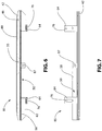
- the flow passageway 55 extends from a bottom surface 78 of the foam body 42 to a top surface 80 of the foam body 42.
- An inlet port 81 is defined by the applicator support 50 and the foam body 42.
- the inlet port 81 is in fluid communication with the flow passageway 55.
- the inlet port 81 is generally positioned at a central portion of the applicator support 50 and foam body 42, although other suitable positions for the inlet port 81 may be used.
- the top surface 80 of the foam body 42 defines an exit port 82 of the flow passageway 55.
- the exit port 82 of the flow passageway 55 is substantially slot-shaped, although other suitably shapes for the exit port 82 may be utilized.
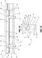
- the exit port 82 may be a slit in the foam body 42 or may be substantially circular-shaped (as shown in Figs. 13-15 ).
- the substantially slot-shaped exit port 82 closes at the top surface 80 of the foam body 42 due to the compression of the foam body 42 in the mounting position thereby allowing more free flow through the flow passageway 55 while sealing air from the exit port 82 at the top surface 80.
- the flow passageway 55 is also angled towards the front surface 44 of the foam body 42 as it extends from the bottom surface 78 to the top surface 80.
- the flow passageway 55 may extend in a direction that is perpendicular with the top surface 80 of the foam body 42 or any other suitable direction through the foam body 42. Although a single flow passageway 55 in the foam body 42 is disclosed, the applicator 40 may include a number of flow passageways 55.
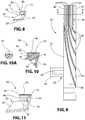
- a further embodiment of a rail applicator 85 is shown.
- the rail applicator is similar to the rail applicator 40 shown in Figs. 1-3 and described above.
- the applicator 85 also includes a polymeric or rubber foam body 42 having a front surface 44 and a rear surface 46 and an applicator support 50 for positioning and supporting the applicator 85.
- the foam body 42 defines a flow passageway 55 that extends through the foam body 42 for the friction modifying material to flow through.
- the applicator support 50 includes an elongate body 58 having an upper surface 60 and a lower surface 62. A pair of extensions 64 extends from the elongate body 58.
- friction modifying material is provided to the flow passageway 55 via an inlet port 87 defined by the applicator support 50 and the foam body 42.
- the inlet port 87 is generally positioned at a central portion of the applicator support 50 and foam body 42, although other suitable positions for the inlet port 87 may be used.
- the inlet port 87 is in fluid communication with the flow passageway 55.
- the friction modifying material may be supplied to the inlet port 87 via piping or tubing (not shown) that leads to a reservoir (not shown) containing the friction modifying material.
- a pump actuator (not shown) is secured to the rail and includes a pump that is in fluid communication with the reservoir.
- the flow passageway 55 is wider at a top portion 89 of the foam body 42 than a lower portion 91 of the foam body 42.
- the flow passageway 55 tapers outward as it extends from the bottom surface 78 to the top surface 80 of the foam body 42.
- the top surface 80 of the foam body 42 defines a plurality of ribs 93 generally extending in a longitudinal direction of the foam body 42.
- the ribs 93 extend outward from the top surface 80 of the foam body 42.
- Each of the ribs 93 include curved portions 95 at their ends that extend toward the front surface 44 of the foam body 42.
- the ribs 93 are configured to direct friction modifying material towards the front surface 44 of the foam body 42.
- FIG. 13-15 another embodiment of a rail applicator assembly 97 is shown.
- the rail applicator assembly 97 is similar to the rail applicator assembly 10 shown in Figs. 1-3 .
- the exit port 82 defined by the top surface 80 of the foam body 42 is substantially circular-shaped.
- the applicator 40 is positioned adjacent to the head portion 21 of the rail 15 in order to apply friction modifying material to the rail 15.
- the foam body 42 of the applicator 40 engages the head portion 21 of the rail, which compresses the foam body 42.
- Friction modifying material 99 is applied to the head portion 21 of the rail 15 by distributing the friction modifying material 99 through the flow passageway 55 and exiting the flow passageway 55 via the exit port 82.
- the foam body 42 contains the friction modifying material and directs the friction modifying material toward the crown 27 of the rail 15. As shown in Fig.
- the wheel 101 engages and compresses the foam body 42 to define a depressed portion 103.
- the foam body 42 of the applicator 40 is configured to conform to the profile of the rail wheel 101 such that the applicator 40 accommodates new rail wheels or worn rail wheels having varying dimensions.
- the depressed portion 103 of the foam body 42 caused by the passing wheel 101 expands and the foam body 42 returns to its original form. Further, as shown more clearly in Figs.
- the foam body 42 of the applicator 40 is compressed against the rail 15 such that the exit port 82 is substantially closed when friction modifying material is not exiting through the exit port 82.
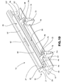
- FIG. 19-21 yet another embodiment of a rail applicator assembly 105 is shown.
- the rail applicator assembly 105 is similar to the rail applicator assembly 10 shown in Figs. 1-3 .
- the applicator support 50 of the present embodiment further includes an upward flange 107 extending from the upper surface of the elongate body 58.
- the upward flange 107 is positioned adjacent the rear surface 46 of the foam body 42 and is configured to provide support for the foam body 42 during compression by a passing rail wheel.
Landscapes
- Engineering & Computer Science (AREA)
- Mechanical Engineering (AREA)
- Architecture (AREA)
- Civil Engineering (AREA)
- Structural Engineering (AREA)
- Coating Apparatus (AREA)
- Platform Screen Doors And Railroad Systems (AREA)
- Machines For Laying And Maintaining Railways (AREA)
Claims (15)
- Schienenapplikatoranordnung, umfassend
eine Schiene (15), welche einen Kopfabschnitt (21), einen Basisabschnitt (17) und Stegabschnitt (23) aufweist, welcher sich zwischen dem Kopfabschnitt (21) und dem Basisabschnitt (17) erstreckt, wobei der Kopfabschnitt (21) eine Feldoberfläche definiert; und
einen Applikator (40) zum Aufbringen eines reibungsmodifizierenden Materials auf die Feldoberfläche von der Schiene (15), wobei der Applikator (40) einen länglichen Polymer- oder Schaumgummi-Körper (42) und einen Applikatorträger (50) umfasst, wobei der längliche Polymer- oder Schaumgummi-Körper (42) an dem Applikatorträger (50) gesichert ist und einen Strömungsdurchgang (55) definiert, welcher aus einem Kanal besteht, welcher sich durch den länglichen Polymer- oder Schaumgummi-Körper (42) hindurch erstreckt, damit das reibungsmodifizierende Material dadurch hindurch fließen kann, wobei der Applikator (40) gegen die Feldoberfläche montiert ist, wobei eine obere Oberfläche (80) von dem länglichen Polymer- oder Schaumgummi-Körper (42) nach unten in Richtung zu der Feldoberfläche geneigt ist,
wobei der längliche Polymer- oder Schaumgummi-Körper komprimiert wird, wenn er durch ein Passieren des Schienenrads kontaktiert wird, und dann zu seiner Originalform zurückkehrt. - Schienenapplikatoranordnung gemäß Anspruch 1, wobei sich der Strömungsdurchgang (55) von einer unteren Oberfläche (78) zu der oberen Oberfläche (80) von dem länglichen Polymer- oder Schaumgummi-Körper (42) erstreckt, wobei die obere Oberfläche (80) des länglichen Polymer- oder Schaumgummi-Körpers (42) eine Ausgangsöffnung (82) von dem Strömungsdurchgang (500) definiert.
- Schienenapplikatoranordnung gemäß Anspruch 2, wobei der Strömungsdurchgang (55) in Richtung zu einer vorderen Oberfläche (44) von dem länglichen Polymer- oder Schaumgummi-Körper (42) abgewinkelt ist, wobei der Strömungsdurchgang (55) an einem oberen Abschnitt (89) von dem länglichen Polymer- oder Schaumgummi-Körper (42) breiter ist als ein unterer Abschnitt (91) von dem länglichen Polymer- oder Schaumgummi-Körper (42), oder eine Kombination davon.
- Schienenapplikatoranordnung gemäß Anspruch 2, wobei die Ausgangsöffnung (82) von dem Strömungsdurchgang (55) im Wesentlichen schlitzförmig oder kreisförmig ist.
- Schienenapplikatoranordnung gemäß irgendeinem der Ansprüche 1 bis 4, wobei der Applikatorträger (50) einen im Allgemeinen C-förmigen länglichen Körper (58) mit einem Paar von Verlängerungen (64) umfasst, welche sich von dem im Allgemeinen C-förmigen länglichen Körper (58) erstrecken.
- Schienenapplikatoranordnung gemäß irgendeinem der Ansprüche 1 bis 5, wobei die obere Oberfläche (80) von dem länglichen Polymer- oder Schaumgummi-Körper (42) eine Lamelle (93) enthält, welche sich in einer longitudinalen Richtung von dem länglichen Polymer- oder Schaumgummi-Körper (42) erstreckt.
- Schienenapplikatoranordnung gemäß irgendeinem der Ansprüche 1 bis 6, wobei der längliche Polymer- oder Schaumgummi-Körper (42) ausreichend elastisch und flexibel ist, um sich aus dem Weg zu biegen, wenn er durch das Schienenrad kontaktiert wird, und danach zu seiner Originalposition zurückzukehren.
- Schienenapplikator, umfassend:einen länglichen Polymer- oder Schaumgummi-Körper (42), welcher konfiguriert ist, um ein reibungsmodifizierendes Material auf eine Feldoberfläche von einem Kopfabschnitt (21) von einer Schiene (15) aufzubringen, wobei der längliche Polymer- oder Schaumgummi-Körper (42) einen Strömungsdurchgang (55) definiert, welcher aus einem Kanal besteht, der sich durch den länglichen Polymer- oder Schaumgummi-Körper (42) hindurch erstreckt, damit das reibungsmodifizierende Material dadurch hindurch fließen kann; undeinen Applikatorträger (50), wobei der längliche Polymer- oder Schaumgummi-Körper (42) an dem Applikatorträger (50) gesichert ist,wobei der längliche Polymer- oder Schaumgummi-Körper (42) komprimiert wird, wenn er durch einen passierendes Schienenrad kontaktiert wird und dann zu seiner Originalform zurückkehrt.
- Schienenapplikator gemäß Anspruch 8, wobei der Strömungsdurchgang (55) sich von einer unteren Oberfläche (7) zu einer oberen Oberfläche (80) von dem länglichen Polymer- oder Schaumgummi-Körper (42) erstreckt, wobei die obere Oberfläche (80) von dem länglichen Polymer- oder Schaumgummi-Körper (42) eine Ausgangsöffnung (82) von dem Strömungsdurchgang (55) definiert.
- Schienenapplikator gemäß Anspruch 9, wobei der Strömungsdurchgang (55) in Richtung zu einer vorderen Oberfläche (44) von dem länglichen Polymer- oder Schaumgummi-Körper (42) abgewinkelt ist, wobei der Strömungsdurchgang (55) breiter an einem oberen Abschnitt (89) von dem länglichen Polymer- oder Schaumgummi-Körper (42) ist als an einem unteren Abschnitt (91) von dem länglichen Polymer- oder Schaumgummi-Körper (42), oder eine Kombination davon.
- Schienenapplikator gemäß Anspruch 9, wobei die Ausgangsöffnung (82) von dem Strömungsdurchgang (55) im Wesentlichen schlitzförmig oder im Wesentlichen kreisförmig ist.
- Schienenapplikator gemäß irgendeinem der Ansprüche 9 bis 11, wobei die obere Oberfläche (80) von dem länglichen Polymer- oder Schaumgummi-Körper (42) eine Lamelle (93) enthält, welche sich entlang einer longitudinalen Richtung von dem länglichen Polymer- oder Schaumgummi-Körper (42) erstreckt.
- Schienenapplikator gemäß irgendeinem der Ansprüche 8 bis 12, wobei der längliche Polymer- oder Schaumgummi-Körper (42) ausreichend elastisch und flexibel ist, um sich aus dem Weg zu biegen, wenn er durch das Schienenrad kontaktiert wird, und danach zu seiner Originalposition zurückzukehren.
- Verfahren zum Aufbringen eines reibungsmodifizierenden Materials auf eine Schiene, umfassend:in Eingriff nehmen einer Feldoberfläche von einem Kopfteil (21) einer Schiene (15) mit dem Applikator gemäß irgendeinem der Ansprüche 8 bis 13; undAufbringen eines reibungsmodifizierenden Materials auf die Feldoberfläche von dem Kopfabschnitt (21) der Schiene (15) durch Verteilen des reibungsmodifizierenden Materials durch den Strömungsdurchgang (55) und Austreten aus dem Strömungsdurchgang (55) über eine Ausgangsöffnung (82).
- Verfahren gemäß Anspruch 14, weiterhin umfassend ein Komprimieren des Applikators (40) gegen die Schiene (21), so dass die Ausgangsöffnung (82) im Wesentlichen geschlossen ist, bevor das reibungsmodifizierende Material durch die Ausgangsöffnung (82) austritt.
Priority Applications (1)
| Application Number | Priority Date | Filing Date | Title |
|---|---|---|---|
| PL10781279T PL2435284T3 (pl) | 2009-05-29 | 2010-05-28 | Listwa z pianki na górę szyny |
Applications Claiming Priority (3)
| Application Number | Priority Date | Filing Date | Title |
|---|---|---|---|
| US18221709P | 2009-05-29 | 2009-05-29 | |
| US12/788,971 US8955645B2 (en) | 2009-05-29 | 2010-05-27 | Top of rail foam bar |
| PCT/US2010/036582 WO2010138819A2 (en) | 2009-05-29 | 2010-05-28 | Top of rail foam bar |
Publications (3)
| Publication Number | Publication Date |
|---|---|
| EP2435284A2 EP2435284A2 (de) | 2012-04-04 |
| EP2435284A4 EP2435284A4 (de) | 2017-03-29 |
| EP2435284B1 true EP2435284B1 (de) | 2020-12-23 |
Family
ID=43218970
Family Applications (1)
| Application Number | Title | Priority Date | Filing Date |
|---|---|---|---|
| EP10781279.4A Active EP2435284B1 (de) | 2009-05-29 | 2010-05-28 | Schienenschaumstoffbalken |
Country Status (9)
| Country | Link |
|---|---|
| US (2) | US8955645B2 (de) |
| EP (1) | EP2435284B1 (de) |
| CN (1) | CN102458956B (de) |
| AU (1) | AU2010253819B2 (de) |
| BR (2) | BR122019025475B1 (de) |
| CA (1) | CA2763205C (de) |
| ES (1) | ES2862930T3 (de) |
| PL (1) | PL2435284T3 (de) |
| WO (1) | WO2010138819A2 (de) |
Families Citing this family (19)
| Publication number | Priority date | Publication date | Assignee | Title |
|---|---|---|---|---|
| AU2009293041B2 (en) | 2008-09-19 | 2014-10-09 | L.B. Foster Rail Technologies, Inc. | Wiping bar quick clamp |
| US9914465B2 (en) | 2009-05-29 | 2018-03-13 | L.B. Foster Rail Technologies, Inc. | Top of rail resilient bar |
| US8955645B2 (en) | 2009-05-29 | 2015-02-17 | L.B. Foster Rail Technologies, Inc. | Top of rail foam bar |
| GB2498385B (en) * | 2012-01-13 | 2018-08-29 | Rowe Hankins Ltd | Apparatus and method for applying lubricant to railway vehicle wheels |
| CN102602422A (zh) * | 2012-03-30 | 2012-07-25 | 南京贝奇尔机械有限公司 | 固定式轨道润滑系统 |
| US9096242B2 (en) * | 2012-08-23 | 2015-08-04 | L.B. Foster Rail Technologies, Inc. | Gauge face lubrication |
| US10960907B2 (en) | 2013-01-07 | 2021-03-30 | Whitmore Manufacturing, Llc | Top of rail applicator |
| US10173700B2 (en) | 2013-01-07 | 2019-01-08 | Whitmore Manufacturing, Llc | Top of rail applicator and method of using the same |
| US9499177B2 (en) | 2013-08-26 | 2016-11-22 | John A. Wade | System and method of modifying the friction of railroad tracks |
| EP2910681A1 (de) * | 2014-02-21 | 2015-08-26 | Rail Road Systems B.V. | Befeuchtungsvorrichtung für eine Schiene und Schienensystem |
| CA2970188A1 (en) * | 2014-12-12 | 2016-06-16 | Whitmore Manufacturing, Llc | Top of rail applicator and method of using the same |
| US10358152B2 (en) * | 2015-08-28 | 2019-07-23 | Loram Maintenance Of Way, Inc. | Method and apparatus for gauge-face lubrication |
| USD800604S1 (en) * | 2015-08-28 | 2017-10-24 | Loram Maintenance Of Way, Inc. | Gauge face lubrication bar |
| USD801226S1 (en) * | 2015-08-28 | 2017-10-31 | Loram Maintenance Of Way, Inc. | Gauge face lubrication bar |
| US10286831B2 (en) * | 2016-05-18 | 2019-05-14 | Ford Global Technologies, Llc | Cargo management system incorporating a mat of memory foam |
| EP3484757B1 (de) * | 2016-07-14 | 2022-07-06 | L.B. Foster Rail Technologies, Corp. | Schienenöffnungseinsatz |
| WO2018157226A1 (en) | 2017-03-01 | 2018-09-07 | L.B. Foster Rail Technologies, Corp. | Adhesion enhancement compositions |
| JP6866189B2 (ja) * | 2017-03-06 | 2021-04-28 | 日本製鉄株式会社 | レール |
| EP3659895A1 (de) * | 2018-11-29 | 2020-06-03 | Whitmore Manufacturing, LLC. | Verbesserter oberteil eines schienenoberkantenapplikators |
Family Cites Families (85)
| Publication number | Priority date | Publication date | Assignee | Title |
|---|---|---|---|---|
| US804787A (en) * | 1905-03-08 | 1905-11-14 | Frank L Young | Device for preventing railway signal and switch appliances from freezing or clogging. |
| US1097704A (en) * | 1913-07-31 | 1914-05-26 | James Cassidy | Wheel and rail lubricator. |
| US1205711A (en) * | 1915-11-01 | 1916-11-21 | Charles H Clark | Rail-lubricating device. |
| US1546778A (en) * | 1924-05-09 | 1925-07-21 | Niff Michael J De | Track construction |
| US1630584A (en) * | 1926-02-17 | 1927-05-31 | William H Schneider | Railway-track joint |
| US1669603A (en) * | 1926-04-16 | 1928-05-15 | John R Derrick | Lubricating device |
| US1728412A (en) * | 1927-07-16 | 1929-09-17 | Albert G Humphries | Track lubricator |
| US1803923A (en) * | 1928-03-06 | 1931-05-05 | American Valve & Meter Company | Wheel and rail lubricator |
| US1745213A (en) * | 1928-08-01 | 1930-01-28 | Wallace M Gray | Track-lubricating apparatus |
| US1839427A (en) | 1928-10-11 | 1932-01-05 | Maintenance Equipment Company | Wheel flange oiler |
| US1878259A (en) * | 1929-05-18 | 1932-09-20 | John A Bodkin | Flange and rail lubricator |
| US1940527A (en) * | 1930-06-10 | 1933-12-19 | American Valve And Meter Compa | Means for lubricating car wheels and rails |
| US1968809A (en) * | 1930-07-10 | 1934-08-07 | Goodrich Co B F | Artificial turf and method of making the same |
| US1939846A (en) * | 1930-07-14 | 1933-12-19 | Goodrich Co B F | Artificial turf and method of making the same |
| US2018402A (en) * | 1931-06-01 | 1935-10-22 | Maintenance Equipment Company | Track lubricator |
| US1979447A (en) * | 1932-07-11 | 1934-11-06 | Butcher Edwin George | Railway and tramway rail and wheel flange lubrication |
| GB415174A (en) | 1933-03-20 | 1934-08-23 | London Electric Railway Compan | Improvements in or relating to the lubrication of check or guard rails on railway curves |
| US1978906A (en) * | 1934-01-12 | 1934-10-30 | Chillingworth Mfg Company | Wheel flange and rail lubricator |
| US2185810A (en) * | 1936-05-29 | 1940-01-02 | American Brake Shoe & Foundry | Rail lubricator |
| US2152696A (en) * | 1937-02-02 | 1939-04-04 | William F Huck | Railway track lubricating device |
| US2272774A (en) * | 1939-01-27 | 1942-02-10 | John T Mcgarry | Rail lubricator |
| US2231394A (en) | 1939-08-29 | 1941-02-11 | Reece Oliver | Rail and wheel flange lubricator |
| US2262852A (en) * | 1940-06-22 | 1941-11-18 | Maintenance Equipment Company | Track lubricator |
| US2555615A (en) * | 1945-02-14 | 1951-06-05 | Stern Charles | Rail and wheel lubricator |
| US2489182A (en) * | 1946-08-29 | 1949-11-22 | William F Huck | Railway track lubricating device |
| US2821263A (en) * | 1954-12-09 | 1958-01-28 | Kerler Philip Henry | Rail and flange lubricator |
| US2887179A (en) | 1957-07-19 | 1959-05-19 | Moore And Steele Corp | Rail and flange lubricator |
| US2980942A (en) * | 1959-12-01 | 1961-04-25 | Jr Ward Dabney | Lubricating and coating slipper |
| GB941408A (en) * | 1961-09-20 | 1963-11-13 | P & M Co England Ltd | Improvements in or relating to actuating mechanism for rail-and-flange lubricating apparatus for railway tracks |
| US3491338A (en) * | 1967-04-17 | 1970-01-20 | Us Air Force | System for synchronizing a receiver and transmitter at opposite ends of a transmission path and for evaluating the noise level thereof |
| CA879784A (en) * | 1969-03-20 | 1971-08-31 | C. Ross John | Applicator |
| JPS51160305U (de) * | 1975-06-13 | 1976-12-20 | ||
| US4088078A (en) * | 1976-06-04 | 1978-05-09 | Westinghouse Air Brake Company | Lubricating apparatus for reducing squeal noise of a railroad car wheel when passing through a car retarder |
| US4220322A (en) * | 1979-02-08 | 1980-09-02 | Hobday Harold W | One-hand operated, ratchet-actuated, quick-set C-clamp |
| US4436294A (en) * | 1982-02-22 | 1984-03-13 | Irelan Robert L | One hand clamping device |
| DE3526653A1 (de) | 1985-07-25 | 1987-02-05 | Vossloh Werke Gmbh | Schienenbefestigung mittels einer elastischen spannklemme |
| US4915195A (en) * | 1988-03-11 | 1990-04-10 | Dial Darrell D | Apparatus for lubricating railroad vehicle wheel flanges |
| US5156508A (en) * | 1989-12-27 | 1992-10-20 | Grisley Kenneth M | Cam action clamp |
| US5348120A (en) * | 1991-04-18 | 1994-09-20 | Portec Inc. | Rail lubrication apparatus |
| DE4136647A1 (de) * | 1991-06-22 | 1992-12-24 | Clouth Gummiwerke Ag | Absorptionsmatte, insbesondere fuer organische kohlenwasserstoffe |
| JPH05145401A (ja) * | 1991-11-21 | 1993-06-11 | Mitsubishi Electric Corp | レベル変換回路 |
| US5217213A (en) | 1992-05-18 | 1993-06-08 | Lii Liang Kuen | Quick release C-clamp |
| CN2136780Y (zh) * | 1992-09-29 | 1993-06-23 | 北京市海淀区怡洋电子技术研究所 | 一种车轮与钢轨的润滑装置 |
| US5394958A (en) * | 1992-12-22 | 1995-03-07 | Portec Inc. | Rail lubrication apparatus |
| US5518085A (en) * | 1995-02-21 | 1996-05-21 | Portec - Rmp Division | Assembly for applying solid material to wheels |
| AUPN254995A0 (en) * | 1995-04-21 | 1995-05-18 | Craft Nominees Pty Ltd | Rail head lubricating apparatus |
| US5641037A (en) * | 1995-06-06 | 1997-06-24 | Portec, Inc., R M P Division | Rail lubrication apparatus |
| US5957241A (en) * | 1997-10-10 | 1999-09-28 | Anderson; Charlie Roy | Oil drip mat apparatus |
| US5996736A (en) * | 1998-03-11 | 1999-12-07 | Danny Stankiewicz | Ladder locking device |
| US6401867B1 (en) * | 1998-04-16 | 2002-06-11 | Thk Co., Ltd. | Lubricant supply system |
| US6010268A (en) * | 1998-12-15 | 2000-01-04 | Prolong Super Lubricants, Inc. | Sponge applicator device |
| US6971479B1 (en) * | 1999-04-08 | 2005-12-06 | Portec Rail Products, Inc. | Top of rail applicator |
| US6899940B2 (en) * | 1999-09-29 | 2005-05-31 | Peter Steven Leriget | Absorbent mat assembly |
| US6529584B1 (en) | 1999-10-13 | 2003-03-04 | Rahsaan, Inc. | Audio program delivery system |
| US6250621B1 (en) * | 2000-03-06 | 2001-06-26 | Great Neck Saw Manufacturers, Inc. | Clamp |
| US8074772B2 (en) * | 2000-04-07 | 2011-12-13 | Portec Rail Products, Inc. | Top of rail applicator |
| JP2002037068A (ja) | 2000-07-21 | 2002-02-06 | Hirabayashi Seisakusho:Kk | 自動レール塗油装置 |
| US6719095B2 (en) * | 2000-09-22 | 2004-04-13 | Lincoln Industrial Corporation | Railroad track lubrication and monitoring thereof |
| US6855673B2 (en) | 2002-11-08 | 2005-02-15 | Kelsan Technologies Corporation | Freeze tolerant friction control compositions |
| JP2002145062A (ja) | 2000-11-16 | 2002-05-22 | Ito Tekkosho:Kk | レールと車輪間への給液装置及び給液方法 |
| US6475594B2 (en) * | 2001-01-05 | 2002-11-05 | Sorbent Products Co., Inc. | Sorbent mat assembly |
| US6854563B2 (en) * | 2001-12-17 | 2005-02-15 | General Electric Company | Wayside rail lubrication apparatus and method |
| US6742624B2 (en) * | 2002-01-29 | 2004-06-01 | Lincoln Industrial Corporation | Railroad rail lubricating apparatus |
| JP2003276604A (ja) | 2002-03-26 | 2003-10-02 | Railway Technical Res Inst | フランジ摩擦低減装置および方法 |
| US6759372B2 (en) * | 2002-04-12 | 2004-07-06 | Kelsan Technologies Corp. | Friction control composition with enhanced retentivity |
| WO2003095283A2 (en) | 2002-05-08 | 2003-11-20 | Portec Rail Products, Inc. | Skirt for top of rail applicator |
| AU2004236042B2 (en) * | 2003-05-07 | 2009-12-03 | Armscor Business (Proprietary) Limited | Clamp for rail a transducer |
| US20080047780A1 (en) * | 2003-05-08 | 2008-02-28 | Portec Rail Products, Inc. | Skirt for top of rail applicator |
| US6817801B1 (en) | 2003-05-14 | 2004-11-16 | The Valvoline Company, A Division Of Ashland, Inc. | Automotive interior liquid applicator |
| US7216558B2 (en) * | 2003-10-03 | 2007-05-15 | Tranergy Corporation | Wheel sensor assembly for rail base mounting |
| US7557147B2 (en) * | 2004-03-17 | 2009-07-07 | Dow Global Technologies Inc. | Soft foams made from interpolymers of ethylene/alpha-olefins |
| US7160378B2 (en) | 2004-08-13 | 2007-01-09 | Kelsan Technologies Corp. | Modified friction control compositions |
| WO2006080071A1 (ja) | 2005-01-27 | 2006-08-03 | Ito Ironworks Corporation | レール塗液装置 |
| GB0702232D0 (en) | 2007-02-06 | 2007-03-14 | Sutton Charles W | Grease distribution bar |
| CA2622561C (en) * | 2007-02-21 | 2015-09-29 | Portec Rail Products, Inc. | Grease guide |
| US7578388B2 (en) * | 2007-04-27 | 2009-08-25 | The Clorox Company | Retail display for pump dispenser for use with substrates |
| US20090000869A1 (en) * | 2007-06-27 | 2009-01-01 | Lincoln Industrial Corporation | Apparatus for Applying a Pumpable Material to a Rail Head |
| US8584804B2 (en) * | 2007-06-27 | 2013-11-19 | Lincoln Industrial Corporation | Apparatus for applying a pumpable material to a rail head |
| TW200911472A (en) * | 2007-07-10 | 2009-03-16 | Seber Design Group Inc | Ratcheting C-clamp |
| AU2009293041B2 (en) | 2008-09-19 | 2014-10-09 | L.B. Foster Rail Technologies, Inc. | Wiping bar quick clamp |
| WO2010033907A2 (en) | 2008-09-19 | 2010-03-25 | Portec Rail Products, Inc. | Hinged clamp |
| US8955645B2 (en) | 2009-05-29 | 2015-02-17 | L.B. Foster Rail Technologies, Inc. | Top of rail foam bar |
| US9914465B2 (en) | 2009-05-29 | 2018-03-13 | L.B. Foster Rail Technologies, Inc. | Top of rail resilient bar |
| US8235307B2 (en) * | 2009-11-06 | 2012-08-07 | Twinco Manufacturing Co., Inc. | Clamp for connecting a wire to a rail |
| US9096242B2 (en) | 2012-08-23 | 2015-08-04 | L.B. Foster Rail Technologies, Inc. | Gauge face lubrication |
-
2010
- 2010-05-27 US US12/788,971 patent/US8955645B2/en active Active
- 2010-05-28 AU AU2010253819A patent/AU2010253819B2/en active Active
- 2010-05-28 WO PCT/US2010/036582 patent/WO2010138819A2/en not_active Ceased
- 2010-05-28 ES ES10781279T patent/ES2862930T3/es active Active
- 2010-05-28 BR BR122019025475-3A patent/BR122019025475B1/pt active IP Right Grant
- 2010-05-28 EP EP10781279.4A patent/EP2435284B1/de active Active
- 2010-05-28 CN CN201080031049.3A patent/CN102458956B/zh active Active
- 2010-05-28 BR BRPI1014926-0A patent/BRPI1014926B1/pt active IP Right Grant
- 2010-05-28 PL PL10781279T patent/PL2435284T3/pl unknown
- 2010-05-28 CA CA2763205A patent/CA2763205C/en active Active
-
2015
- 2015-02-12 US US14/620,406 patent/US9440665B2/en active Active
Non-Patent Citations (1)
| Title |
|---|
| None * |
Also Published As
| Publication number | Publication date |
|---|---|
| WO2010138819A2 (en) | 2010-12-02 |
| US20150158509A1 (en) | 2015-06-11 |
| CA2763205A1 (en) | 2010-12-02 |
| EP2435284A2 (de) | 2012-04-04 |
| BR122019025475B1 (pt) | 2021-04-13 |
| BRPI1014926A2 (pt) | 2016-04-19 |
| CN102458956A (zh) | 2012-05-16 |
| WO2010138819A3 (en) | 2011-02-24 |
| EP2435284A4 (de) | 2017-03-29 |
| BRPI1014926B1 (pt) | 2020-03-17 |
| AU2010253819B2 (en) | 2015-06-11 |
| CN102458956B (zh) | 2016-01-13 |
| AU2010253819A1 (en) | 2011-12-08 |
| US8955645B2 (en) | 2015-02-17 |
| US20100300810A1 (en) | 2010-12-02 |
| US9440665B2 (en) | 2016-09-13 |
| PL2435284T3 (pl) | 2021-08-02 |
| ES2862930T3 (es) | 2021-10-08 |
| CA2763205C (en) | 2016-06-14 |
Similar Documents
| Publication | Publication Date | Title |
|---|---|---|
| US9440665B2 (en) | Top of rail foam bar | |
| US10358153B2 (en) | Top of rail foam bar | |
| US9096242B2 (en) | Gauge face lubrication | |
| US9022173B2 (en) | Grease guide | |
| US20140138187A1 (en) | Apparatus for delivering a pumpable material to a rail head | |
| US20090000869A1 (en) | Apparatus for Applying a Pumpable Material to a Rail Head | |
| EP1171337A1 (de) | Auftragvorrichtung für die lauffläche einer schiene | |
| US5722509A (en) | Flange oiler | |
| US20040050623A1 (en) | Skirt for top of rail applicator | |
| CA2472248A1 (en) | Railroad rail lubricating apparatus | |
| US2518786A (en) | Railway track lubricating device | |
| CA2854931C (en) | Line distributor, preferably for anti-noise device for rail brakes | |
| GB2267937A (en) | Lubricating railway tracks | |
| CA2869485A1 (en) | Top of rail resilient bar | |
| WO2018010001A1 (en) | Rail port insert | |
| DE50310927D1 (de) | Tropfenabscheideeinrichtung für Luftströmungskanal | |
| WO2006091832A3 (en) | Flow divider arrangement grease distribution system | |
| GB2361269A (en) | Adjustable lubricant dispenser |
Legal Events
| Date | Code | Title | Description |
|---|---|---|---|
| PUAI | Public reference made under article 153(3) epc to a published international application that has entered the european phase |
Free format text: ORIGINAL CODE: 0009012 |
|
| 17P | Request for examination filed |
Effective date: 20111202 |
|
| AK | Designated contracting states |
Kind code of ref document: A2 Designated state(s): AL AT BE BG CH CY CZ DE DK EE ES FI FR GB GR HR HU IE IS IT LI LT LU LV MC MK MT NL NO PL PT RO SE SI SK SM TR |
|
| DAX | Request for extension of the european patent (deleted) | ||
| A4 | Supplementary search report drawn up and despatched |
Effective date: 20170228 |
|
| RIC1 | Information provided on ipc code assigned before grant |
Ipc: E01B 7/26 20060101ALI20170222BHEP Ipc: B61K 3/00 20060101AFI20170222BHEP Ipc: E01B 19/00 20060101ALI20170222BHEP Ipc: B61K 13/00 20060101ALI20170222BHEP Ipc: E01B 9/60 20060101ALI20170222BHEP |
|
| STAA | Information on the status of an ep patent application or granted ep patent |
Free format text: STATUS: EXAMINATION IS IN PROGRESS |
|
| 17Q | First examination report despatched |
Effective date: 20180917 |
|
| RAP1 | Party data changed (applicant data changed or rights of an application transferred) |
Owner name: L.B. FOSTER RAIL TECHNOLOGIES, INC. |
|
| GRAP | Despatch of communication of intention to grant a patent |
Free format text: ORIGINAL CODE: EPIDOSNIGR1 |
|
| STAA | Information on the status of an ep patent application or granted ep patent |
Free format text: STATUS: GRANT OF PATENT IS INTENDED |
|
| INTG | Intention to grant announced |
Effective date: 20200812 |
|
| RIN1 | Information on inventor provided before grant (corrected) |
Inventor name: URMSON, THOMAS W., JR. Inventor name: REDFIELD, MATTHEW P. Inventor name: SINGLETON, STEVEN D. Inventor name: LUCKE, CHRISTOPHER ALAN |
|
| GRAS | Grant fee paid |
Free format text: ORIGINAL CODE: EPIDOSNIGR3 |
|
| GRAA | (expected) grant |
Free format text: ORIGINAL CODE: 0009210 |
|
| STAA | Information on the status of an ep patent application or granted ep patent |
Free format text: STATUS: THE PATENT HAS BEEN GRANTED |
|
| AK | Designated contracting states |
Kind code of ref document: B1 Designated state(s): AL AT BE BG CH CY CZ DE DK EE ES FI FR GB GR HR HU IE IS IT LI LT LU LV MC MK MT NL NO PL PT RO SE SI SK SM TR |
|
| REG | Reference to a national code |
Ref country code: GB Ref legal event code: FG4D |
|
| REG | Reference to a national code |
Ref country code: DE Ref legal event code: R096 Ref document number: 602010066212 Country of ref document: DE |
|
| REG | Reference to a national code |
Ref country code: AT Ref legal event code: REF Ref document number: 1347435 Country of ref document: AT Kind code of ref document: T Effective date: 20210115 |
|
| REG | Reference to a national code |
Ref country code: IE Ref legal event code: FG4D |
|
| REG | Reference to a national code |
Ref country code: CH Ref legal event code: NV Representative=s name: NOVAGRAAF INTERNATIONAL SA, CH |
|
| REG | Reference to a national code |
Ref country code: SE Ref legal event code: TRGR |
|
| PG25 | Lapsed in a contracting state [announced via postgrant information from national office to epo] |
Ref country code: NO Free format text: LAPSE BECAUSE OF FAILURE TO SUBMIT A TRANSLATION OF THE DESCRIPTION OR TO PAY THE FEE WITHIN THE PRESCRIBED TIME-LIMIT Effective date: 20210323 Ref country code: FI Free format text: LAPSE BECAUSE OF FAILURE TO SUBMIT A TRANSLATION OF THE DESCRIPTION OR TO PAY THE FEE WITHIN THE PRESCRIBED TIME-LIMIT Effective date: 20201223 Ref country code: GR Free format text: LAPSE BECAUSE OF FAILURE TO SUBMIT A TRANSLATION OF THE DESCRIPTION OR TO PAY THE FEE WITHIN THE PRESCRIBED TIME-LIMIT Effective date: 20210324 |
|
| REG | Reference to a national code |
Ref country code: AT Ref legal event code: MK05 Ref document number: 1347435 Country of ref document: AT Kind code of ref document: T Effective date: 20201223 |
|
| REG | Reference to a national code |
Ref country code: NL Ref legal event code: MP Effective date: 20201223 |
|
| PG25 | Lapsed in a contracting state [announced via postgrant information from national office to epo] |
Ref country code: LV Free format text: LAPSE BECAUSE OF FAILURE TO SUBMIT A TRANSLATION OF THE DESCRIPTION OR TO PAY THE FEE WITHIN THE PRESCRIBED TIME-LIMIT Effective date: 20201223 Ref country code: BG Free format text: LAPSE BECAUSE OF FAILURE TO SUBMIT A TRANSLATION OF THE DESCRIPTION OR TO PAY THE FEE WITHIN THE PRESCRIBED TIME-LIMIT Effective date: 20210323 |
|
| PG25 | Lapsed in a contracting state [announced via postgrant information from national office to epo] |
Ref country code: HR Free format text: LAPSE BECAUSE OF FAILURE TO SUBMIT A TRANSLATION OF THE DESCRIPTION OR TO PAY THE FEE WITHIN THE PRESCRIBED TIME-LIMIT Effective date: 20201223 Ref country code: NL Free format text: LAPSE BECAUSE OF FAILURE TO SUBMIT A TRANSLATION OF THE DESCRIPTION OR TO PAY THE FEE WITHIN THE PRESCRIBED TIME-LIMIT Effective date: 20201223 |
|
| REG | Reference to a national code |
Ref country code: LT Ref legal event code: MG9D |
|
| PG25 | Lapsed in a contracting state [announced via postgrant information from national office to epo] |
Ref country code: LT Free format text: LAPSE BECAUSE OF FAILURE TO SUBMIT A TRANSLATION OF THE DESCRIPTION OR TO PAY THE FEE WITHIN THE PRESCRIBED TIME-LIMIT Effective date: 20201223 Ref country code: CZ Free format text: LAPSE BECAUSE OF FAILURE TO SUBMIT A TRANSLATION OF THE DESCRIPTION OR TO PAY THE FEE WITHIN THE PRESCRIBED TIME-LIMIT Effective date: 20201223 Ref country code: EE Free format text: LAPSE BECAUSE OF FAILURE TO SUBMIT A TRANSLATION OF THE DESCRIPTION OR TO PAY THE FEE WITHIN THE PRESCRIBED TIME-LIMIT Effective date: 20201223 Ref country code: PT Free format text: LAPSE BECAUSE OF FAILURE TO SUBMIT A TRANSLATION OF THE DESCRIPTION OR TO PAY THE FEE WITHIN THE PRESCRIBED TIME-LIMIT Effective date: 20210423 Ref country code: RO Free format text: LAPSE BECAUSE OF FAILURE TO SUBMIT A TRANSLATION OF THE DESCRIPTION OR TO PAY THE FEE WITHIN THE PRESCRIBED TIME-LIMIT Effective date: 20201223 Ref country code: SK Free format text: LAPSE BECAUSE OF FAILURE TO SUBMIT A TRANSLATION OF THE DESCRIPTION OR TO PAY THE FEE WITHIN THE PRESCRIBED TIME-LIMIT Effective date: 20201223 Ref country code: SM Free format text: LAPSE BECAUSE OF FAILURE TO SUBMIT A TRANSLATION OF THE DESCRIPTION OR TO PAY THE FEE WITHIN THE PRESCRIBED TIME-LIMIT Effective date: 20201223 |
|
| PG25 | Lapsed in a contracting state [announced via postgrant information from national office to epo] |
Ref country code: AT Free format text: LAPSE BECAUSE OF FAILURE TO SUBMIT A TRANSLATION OF THE DESCRIPTION OR TO PAY THE FEE WITHIN THE PRESCRIBED TIME-LIMIT Effective date: 20201223 |
|
| REG | Reference to a national code |
Ref country code: DE Ref legal event code: R097 Ref document number: 602010066212 Country of ref document: DE |
|
| PG25 | Lapsed in a contracting state [announced via postgrant information from national office to epo] |
Ref country code: IS Free format text: LAPSE BECAUSE OF FAILURE TO SUBMIT A TRANSLATION OF THE DESCRIPTION OR TO PAY THE FEE WITHIN THE PRESCRIBED TIME-LIMIT Effective date: 20210423 |
|
| REG | Reference to a national code |
Ref country code: ES Ref legal event code: FG2A Ref document number: 2862930 Country of ref document: ES Kind code of ref document: T3 Effective date: 20211008 |
|
| PG25 | Lapsed in a contracting state [announced via postgrant information from national office to epo] |
Ref country code: AL Free format text: LAPSE BECAUSE OF FAILURE TO SUBMIT A TRANSLATION OF THE DESCRIPTION OR TO PAY THE FEE WITHIN THE PRESCRIBED TIME-LIMIT Effective date: 20201223 |
|
| PLBE | No opposition filed within time limit |
Free format text: ORIGINAL CODE: 0009261 |
|
| STAA | Information on the status of an ep patent application or granted ep patent |
Free format text: STATUS: NO OPPOSITION FILED WITHIN TIME LIMIT |
|
| PG25 | Lapsed in a contracting state [announced via postgrant information from national office to epo] |
Ref country code: DK Free format text: LAPSE BECAUSE OF FAILURE TO SUBMIT A TRANSLATION OF THE DESCRIPTION OR TO PAY THE FEE WITHIN THE PRESCRIBED TIME-LIMIT Effective date: 20201223 |
|
| 26N | No opposition filed |
Effective date: 20210924 |
|
| PG25 | Lapsed in a contracting state [announced via postgrant information from national office to epo] |
Ref country code: LU Free format text: LAPSE BECAUSE OF NON-PAYMENT OF DUE FEES Effective date: 20210528 Ref country code: MC Free format text: LAPSE BECAUSE OF FAILURE TO SUBMIT A TRANSLATION OF THE DESCRIPTION OR TO PAY THE FEE WITHIN THE PRESCRIBED TIME-LIMIT Effective date: 20201223 |
|
| REG | Reference to a national code |
Ref country code: BE Ref legal event code: MM Effective date: 20210531 |
|
| PG25 | Lapsed in a contracting state [announced via postgrant information from national office to epo] |
Ref country code: SI Free format text: LAPSE BECAUSE OF FAILURE TO SUBMIT A TRANSLATION OF THE DESCRIPTION OR TO PAY THE FEE WITHIN THE PRESCRIBED TIME-LIMIT Effective date: 20201223 |
|
| PG25 | Lapsed in a contracting state [announced via postgrant information from national office to epo] |
Ref country code: IE Free format text: LAPSE BECAUSE OF NON-PAYMENT OF DUE FEES Effective date: 20210528 |
|
| PG25 | Lapsed in a contracting state [announced via postgrant information from national office to epo] |
Ref country code: IS Free format text: LAPSE BECAUSE OF FAILURE TO SUBMIT A TRANSLATION OF THE DESCRIPTION OR TO PAY THE FEE WITHIN THE PRESCRIBED TIME-LIMIT Effective date: 20210423 |
|
| PG25 | Lapsed in a contracting state [announced via postgrant information from national office to epo] |
Ref country code: BE Free format text: LAPSE BECAUSE OF NON-PAYMENT OF DUE FEES Effective date: 20210531 |
|
| PG25 | Lapsed in a contracting state [announced via postgrant information from national office to epo] |
Ref country code: HU Free format text: LAPSE BECAUSE OF FAILURE TO SUBMIT A TRANSLATION OF THE DESCRIPTION OR TO PAY THE FEE WITHIN THE PRESCRIBED TIME-LIMIT; INVALID AB INITIO Effective date: 20100528 Ref country code: CY Free format text: LAPSE BECAUSE OF FAILURE TO SUBMIT A TRANSLATION OF THE DESCRIPTION OR TO PAY THE FEE WITHIN THE PRESCRIBED TIME-LIMIT Effective date: 20201223 |
|
| P01 | Opt-out of the competence of the unified patent court (upc) registered |
Effective date: 20230519 |
|
| PG25 | Lapsed in a contracting state [announced via postgrant information from national office to epo] |
Ref country code: MK Free format text: LAPSE BECAUSE OF FAILURE TO SUBMIT A TRANSLATION OF THE DESCRIPTION OR TO PAY THE FEE WITHIN THE PRESCRIBED TIME-LIMIT Effective date: 20201223 |
|
| PG25 | Lapsed in a contracting state [announced via postgrant information from national office to epo] |
Ref country code: TR Free format text: LAPSE BECAUSE OF FAILURE TO SUBMIT A TRANSLATION OF THE DESCRIPTION OR TO PAY THE FEE WITHIN THE PRESCRIBED TIME-LIMIT Effective date: 20201223 |
|
| PG25 | Lapsed in a contracting state [announced via postgrant information from national office to epo] |
Ref country code: MT Free format text: LAPSE BECAUSE OF FAILURE TO SUBMIT A TRANSLATION OF THE DESCRIPTION OR TO PAY THE FEE WITHIN THE PRESCRIBED TIME-LIMIT Effective date: 20201223 |
|
| PGFP | Annual fee paid to national office [announced via postgrant information from national office to epo] |
Ref country code: PL Payment date: 20250423 Year of fee payment: 16 Ref country code: DE Payment date: 20250423 Year of fee payment: 16 |
|
| PGFP | Annual fee paid to national office [announced via postgrant information from national office to epo] |
Ref country code: ES Payment date: 20250606 Year of fee payment: 16 Ref country code: GB Payment date: 20250417 Year of fee payment: 16 |
|
| PGFP | Annual fee paid to national office [announced via postgrant information from national office to epo] |
Ref country code: IT Payment date: 20250428 Year of fee payment: 16 |
|
| PGFP | Annual fee paid to national office [announced via postgrant information from national office to epo] |
Ref country code: FR Payment date: 20250422 Year of fee payment: 16 |
|
| PGFP | Annual fee paid to national office [announced via postgrant information from national office to epo] |
Ref country code: CH Payment date: 20250601 Year of fee payment: 16 |
|
| PGFP | Annual fee paid to national office [announced via postgrant information from national office to epo] |
Ref country code: SE Payment date: 20250429 Year of fee payment: 16 |