US8955645B2 - Top of rail foam bar - Google Patents

Top of rail foam bar Download PDF

Info

Publication number
US8955645B2
US8955645B2 US12/788,971 US78897110A US8955645B2 US 8955645 B2 US8955645 B2 US 8955645B2 US 78897110 A US78897110 A US 78897110A US 8955645 B2 US8955645 B2 US 8955645B2
Authority
US
United States
Prior art keywords
foam body
rail
applicator
flow passageway
modifying material
Prior art date
Legal status (The legal status is an assumption and is not a legal conclusion. Google has not performed a legal analysis and makes no representation as to the accuracy of the status listed.)
Active, expires
Application number
US12/788,971
Other versions
US20100300810A1 (en
Inventor
Steven D. Singleton
W. Thomas Urmson, Jr.
Matthew P. Redfield
Christopher Alan Lucke
Current Assignee (The listed assignees may be inaccurate. Google has not performed a legal analysis and makes no representation or warranty as to the accuracy of the list.)
LB Foster Rail Technologies Corp
Original Assignee
LB Foster Rail Technologies Corp
Priority date (The priority date is an assumption and is not a legal conclusion. Google has not performed a legal analysis and makes no representation as to the accuracy of the date listed.)
Filing date
Publication date
Family has litigation
First worldwide family litigation filed litigation Critical https://patents.darts-ip.com/?family=43218970&utm_source=google_patent&utm_medium=platform_link&utm_campaign=public_patent_search&patent=US8955645(B2) "Global patent litigation dataset” by Darts-ip is licensed under a Creative Commons Attribution 4.0 International License.
Application filed by LB Foster Rail Technologies Corp filed Critical LB Foster Rail Technologies Corp
Priority to US12/788,971 priority Critical patent/US8955645B2/en
Priority to BRPI1014926-0A priority patent/BRPI1014926B1/en
Priority to AU2010253819A priority patent/AU2010253819B2/en
Priority to PCT/US2010/036582 priority patent/WO2010138819A2/en
Priority to CN201080031049.3A priority patent/CN102458956B/en
Priority to ES10781279T priority patent/ES2862930T3/en
Priority to PL10781279T priority patent/PL2435284T3/en
Priority to EP10781279.4A priority patent/EP2435284B1/en
Priority to BR122019025475-3A priority patent/BR122019025475B1/en
Priority to CA2763205A priority patent/CA2763205C/en
Assigned to PORTEC RAIL PRODUCTS, INC. reassignment PORTEC RAIL PRODUCTS, INC. ASSIGNMENT OF ASSIGNORS INTEREST (SEE DOCUMENT FOR DETAILS). Assignors: LUCKE, CHRISTOPHER ALAN, REDFIELD, MATTHEW P., SINGLETON, STEVEN D., URMSON, W. THOMAS, JR.
Publication of US20100300810A1 publication Critical patent/US20100300810A1/en
Priority to US14/075,829 priority patent/US9914465B2/en
Assigned to L.B. FOSTER RAIL TECHNOLOGIES, INC. reassignment L.B. FOSTER RAIL TECHNOLOGIES, INC. CHANGE OF NAME (SEE DOCUMENT FOR DETAILS). Assignors: PORTEC RAIL PRODUCTS, INC.
Priority to US14/620,406 priority patent/US9440665B2/en
Publication of US8955645B2 publication Critical patent/US8955645B2/en
Application granted granted Critical
Priority to US15/452,484 priority patent/US10358153B2/en
Priority to US15/918,511 priority patent/US11273853B2/en
Active legal-status Critical Current
Adjusted expiration legal-status Critical

Links

Images

Classifications

    • BPERFORMING OPERATIONS; TRANSPORTING
    • B61RAILWAYS
    • B61KAUXILIARY EQUIPMENT SPECIALLY ADAPTED FOR RAILWAYS, NOT OTHERWISE PROVIDED FOR
    • B61K3/00Wetting or lubricating rails or wheel flanges
    • EFIXED CONSTRUCTIONS
    • E01CONSTRUCTION OF ROADS, RAILWAYS, OR BRIDGES
    • E01BPERMANENT WAY; PERMANENT-WAY TOOLS; MACHINES FOR MAKING RAILWAYS OF ALL KINDS
    • E01B7/00Switches; Crossings
    • E01B7/26Lubricating of switches

Landscapes

  • Engineering & Computer Science (AREA)
  • Mechanical Engineering (AREA)
  • Architecture (AREA)
  • Civil Engineering (AREA)
  • Structural Engineering (AREA)
  • Coating Apparatus (AREA)
  • Platform Screen Doors And Railroad Systems (AREA)
  • Machines For Laying And Maintaining Railways (AREA)

Abstract

A rail applicator assembly includes a rail having a head portion, a base portion, and a web portion extending between the head portion and the base portion. The head portion defines an outer surface. An applicator for applying a friction modifying material to the surface of the rail includes a foam body and an applicator support. The foam body is secured to the applicator support and defines a flow passageway that extends through the foam body for friction modifying material to flow through.

Description

CROSS REFERENCE TO RELATED APPLICATIONS
This application claims the benefit of U.S. Provisional Application No. 61/182,217, filed May 29, 2009, the entire content of which is hereby incorporated by reference.
BACKGROUND OF THE INVENTION
1. Field of the Invention
The present invention relates to an apparatus for lubricating railroad rails or for applying friction modifiers to railroad rails.
2. Description of Related Art
In the operation of railroads, grease or friction modifier materials are applied onto railroad rails, such as to the top of rails or sides of the rails at curves, turnouts, switches, in some cases, the sections of the track immediately before a switch, and periodically spaced along the length of the track. Such lubricants and friction modifying materials, such as grease, can either reduce or increase the friction where necessary to improve train performance and reduce wear on both the rails and the train wheels. In the case of a friction modifying material that increases the friction between the train wheel and the rail, the practice has been to apply the friction modifier material to the top of the rail to contact the train wheels. Oftentimes, the friction modifying material does not reach the center of the rail or substantial amounts of friction modifying material are wasted by dripping or pouring to a position where the material is not needed.
SUMMARY OF THE INVENTION
In one embodiment, a rail applicator assembly includes a rail having a head portion, a base portion, and a web portion extending between the head portion and the base portion. The head portion defines an outer surface. The rail applicator assembly also includes an applicator for applying a friction modifying material to the outer surface of the rail. The applicator includes a foam body and an applicator support. The foam body is secured to the applicator support and defines a flow passageway that extends through the foam body for friction modifying material to flow through.
A top surface of the foam body may be inclined toward the head portion of the rail and the foam body may engage the head portion of the rail. The flow passageway may extend from a bottom surface to a top surface of the foam body with the top surface of the foam body defining an exit port of the flow passageway. The flow passageway may be angled towards a front surface of the foam body and the flow passageway may be wider at a top portion of the foam body than a lower portion of the foam body. The exit port of the flow passageway may be substantially slot-shaped. The flow passageway may also be substantially circular-shaped. The applicator support may include a generally C-shaped elongate body and may include a pair of extensions that extend from the generally C-shaped elongate body. A top surface of the foam body may include a rib generally extending in a longitudinal direction of the foam body. The rib may include at least one curved portion that extends towards the rail.
In a further embodiment, a rail applicator includes a foam body configured to apply friction modifying material to a surface of a rail. The foam body defines a flow passageway that extends through the foam body for friction modifying material to flow through. The applicator also includes an applicator support with the foam body being secured to the applicator support.
In another embodiment, a method of applying friction modifying material to a rail includes engaging a head portion of a rail with an applicator. The applicator includes a foam body and an applicator support. The foam body is secured to the applicator support and defines a flow passageway that extends through the foam body. The method also includes applying friction modifying material to the head portion of the rail by distributing the friction modifying material through the flow passageway and exiting the flow passageway via an exit port. The method may also include compressing the applicator such that the exit port is substantially closed prior to friction modifying material exiting through the exit port.
BRIEF DESCRIPTION OF THE DRAWINGS
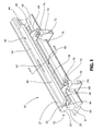
FIG. 1 is a perspective view of a rail applicator according to one embodiment of the present invention;
FIG. 2 is a rear view of the rail applicator shown in FIG. 1;
FIG. 3 is a side view of the rail applicator shown in FIG. 1;
FIG. 4 is a perspective view of a rail applicator according to a further embodiment of the present invention;
FIG. 5 is a top view of the rail applicator shown in FIG. 4;
FIG. 6 is a rear view of the rail applicator shown in FIG. 4;
FIG. 7 is a bottom view of the rail applicator shown in FIG. 4;
FIG. 8 is a side view of the rail applicator shown in FIG. 4;
FIG. 9 is an enlarged partial top view of the rail applicator shown in FIG. 4;
FIG. 10 is a cross-sectional view of the rail applicator shown in FIG. 4, taken along the line A-A of FIG. 9;
FIG. 10A is a detail view of the area shown in FIG. 10;
FIG. 11 is an enlarged side view of the rail applicator shown in FIG. 4;
FIG. 12 is a partial sectional view of an intermediate portion of the rail applicator shown in FIG. 4;
FIG. 13 is a perspective view of a rail applicator according to another embodiment of the present invention;
FIG. 14 is a rear view of the rail applicator shown in FIG. 13;
FIG. 15 is a side view of the rail applicator shown in FIG. 13;
FIG. 16 is a cross-sectional view of the rail applicator shown in FIG. 1, taken along the line B-B of FIG. 1 and showing friction modifying material exiting the applicator;
FIG. 16A is a detail view of the area shown in FIG. 16;
FIG. 17 is a cross-sectional view of the rail applicator shown in FIG. 1, taken along the line B-B of FIG. 1 and showing a rail wheel contacting the applicator;
FIG. 18 is a cross-sectional view of the rail applicator shown in FIG. 1, taken along the line B-B shown in FIG. 1 and showing the applicator returning to form;
FIG. 18A is a detail view of the area shown in FIG. 18;
FIG. 19 is a perspective view of a rail applicator according to yet another embodiment of the present invention;
FIG. 20 is a rear view of the rail applicator shown in FIG. 19; and
FIG. 21 is a side view of the rail applicator shown in FIG. 19.
DESCRIPTION OF THE PREFERRED EMBODIMENTS
For purposes of the description hereinafter, spatial orientation terms, if used, shall relate to the referenced embodiment as it is oriented in the accompanying drawing figures or otherwise described in the following detailed description. However, it is to be understood that the embodiments described hereinafter may assume many alternative variations and embodiments. It is also to be understood that the specific devices illustrated in the accompanying drawing figures and described herein are simply exemplary and should not be considered as limiting.
Referring to FIGS. 1-3, one embodiment of a rail applicator assembly 10 is shown. The rail applicator assembly 10 includes a railroad rail 15 and an applicator 40 for applying a friction modifying material to the rail 15. The rail 15 includes a base portion 17 with flanges 19 extending therefrom and a head portion 21 having a web portion 23, which extends between the head portion 21 and the base portion 17. The head portion 21 of the rail 15 has an outer surface 25 defining a crown 27. The applicator 40 is configured to apply friction modifying material to the head portion 21 of the rail 15. The applicator 40 includes a polymeric or rubber foam body 42 having a front surface 44 and a rear surface 46 and an applicator support 50 for positioning and supporting the applicator 40 adjacent to the head portion 21. The foam body 42 is an elongate member generally having a rectangular shape, although other suitable shapes may be utilized for the foam body 42. The foam body 42 defines a flow passageway 55 that extends through the foam body 42 for the friction modifying material to flow through. The flow passageway 55 may be directly formed in the foam body 42. Alternatively, the flow passageway 55 may be defined by a separate insert (now shown) positioned within the foam body 42. The foam body 42 may be constructed of open-cell neoprene foam, although other suitable polymeric or rubber materials may be used, such as closed-cell foam or a combination of open-cell and closed-cell foam. Alternatively, a hollow rubber member having sufficient resiliency and flexibility may used instead of the foam body 42.
Referring again to FIGS. 1-3, the applicator support 50 includes a generally C-shaped elongate body 58 having an upper surface 60 and a lower surface 62. Further, a pair of extensions 64 extends from the elongate body 58 away from the rail 15. The foam body 42 is secured to the upper surface 60 of the applicator support 50. In particular, the foam body 42 may be directly formed on or bonded to the applicator support 50. The applicator 40 and applicator support 50 are mounted to the rail 15 through two mounting clamps 70. Each of the mounting clamps 70 have a recess 71 configured to receive the flange 19 of the rail 15. Each mounting clamp 70 also includes a bolt (not shown) having a J-shaped end configured to receive the flange 19 and a threaded end that passes through the mounting clamp 70. The mounting clamp 70 may be the same mounting clamp arrangement disclosed in U.S. Pat. No. 7,273,131, which is hereby incorporated herein by reference.
Referring to FIGS. 1 and 2, the extensions 64 of the applicator support 50 are secured to respective mounting clamps 70 via fasteners 72 with spacers 74 being provided between an upper surface of the mounting clamps 70 and the extensions 64. In particular, the fasteners 72, such as bolts, are inserted through respective openings 76 in the extensions 64 and are threadably secured to the mounting clamps 70 thereby securing the applicator support 50 to the mounting clamps 70. The openings 76 in the extensions 64 are generally slot-shaped to allow adjustment of the applicator 40 and support 50 relative to the rail 15, although other suitably shaped openings in each extension 64 may be utilized.
Referring again to FIGS. 1-3, the applicator 40 is arranged to provide friction modifying material adjacent the field surface or outside surface of the rail head 21 as opposed to the gauge surface or inside surface of the rail head 21. The applicator 40 is inclined downwardly toward the head portion 21 of the rail 15 to reduce the flow of friction modifying material in a direction opposite from the rail head 21. In particular, the front surface 44 of the foam body 42, which engages the head 21, has a lower position than the rear surface 46 of the foam body 42 relative to the rail head 21. Thus, the friction modifying material is provided through the flow passageway 55 of the foam body 42 and is maintained at a position adjacent to the outer surface 25 of the rail head 21 by the foam body 42. The foam body 42 deflects out of the way when contacted by a rail wheel and subsequently returns to its original position due to the resiliency and flexibility of the foam body 42.
As shown in FIGS. 1-3, the flow passageway 55 extends from a bottom surface 78 of the foam body 42 to a top surface 80 of the foam body 42. An inlet port 81 is defined by the applicator support 50 and the foam body 42. The inlet port 81 is in fluid communication with the flow passageway 55. The inlet port 81 is generally positioned at a central portion of the applicator support 50 and foam body 42, although other suitable positions for the inlet port 81 may be used. The top surface 80 of the foam body 42 defines an exit port 82 of the flow passageway 55. The exit port 82 of the flow passageway 55 is substantially slot-shaped, although other suitably shapes for the exit port 82 may be utilized. For instance, the exit port 82 may be a slit in the foam body 42 or may be substantially circular-shaped (as shown in FIGS. 13-15). When the foam body 42 is engaging the head portion 21 of the rail 15, the substantially slot-shaped exit port 82 closes at the top surface 80 of the foam body 42 due to the compression of the foam body 42 in the mounting position thereby allowing more free flow through the flow passageway 55 while sealing air from the exit port 82 at the top surface 80. The flow passageway 55 is also angled towards the front surface 44 of the foam body 42 as it extends from the bottom surface 78 to the top surface 80. The flow passageway 55, however, may extend in a direction that is perpendicular with the top surface 80 of the foam body 42 or any other suitable direction through the foam body 42. Although a single flow passageway 55 in the foam body 42 is disclosed, the applicator 40 may include a number of flow passageways 55.
Referring to FIGS. 4-12, a further embodiment of a rail applicator 85 is shown. The rail applicator is similar to the rail applicator 40 shown in FIGS. 1-3 and described above. The applicator 85 also includes a polymeric or rubber foam body 42 having a front surface 44 and a rear surface 46 and an applicator support 50 for positioning and supporting the applicator 85. As shown more clearly in FIGS. 10 and 11, the foam body 42 defines a flow passageway 55 that extends through the foam body 42 for the friction modifying material to flow through. The applicator support 50 includes an elongate body 58 having an upper surface 60 and a lower surface 62. A pair of extensions 64 extends from the elongate body 58.
Referring again to FIGS. 4-12, friction modifying material is provided to the flow passageway 55 via an inlet port 87 defined by the applicator support 50 and the foam body 42. The inlet port 87 is generally positioned at a central portion of the applicator support 50 and foam body 42, although other suitable positions for the inlet port 87 may be used. As shown more clearly in FIG. 10, the inlet port 87 is in fluid communication with the flow passageway 55. The friction modifying material may be supplied to the inlet port 87 via piping or tubing (not shown) that leads to a reservoir (not shown) containing the friction modifying material. A pump actuator (not shown) is secured to the rail and includes a pump that is in fluid communication with the reservoir.
As shown in FIG. 12, the flow passageway 55 is wider at a top portion 89 of the foam body 42 than a lower portion 91 of the foam body 42. In particular, the flow passageway 55 tapers outward as it extends from the bottom surface 78 to the top surface 80 of the foam body 42. The top surface 80 of the foam body 42 defines a plurality of ribs 93 generally extending in a longitudinal direction of the foam body 42. The ribs 93 extend outward from the top surface 80 of the foam body 42. Each of the ribs 93 include curved portions 95 at their ends that extend toward the front surface 44 of the foam body 42. The ribs 93 are configured to direct friction modifying material towards the front surface 44 of the foam body 42. Although a single flow passageway 55, inlet port 87, and exit port 82 are disclosed, the rail applicator 85 may include a number of flow passageways, inlet ports, and exit ports.
Referring to FIGS. 13-15, another embodiment of a rail applicator assembly 97 is shown. The rail applicator assembly 97 is similar to the rail applicator assembly 10 shown in FIGS. 1-3. Rather than providing a substantially slot-shaped exit port, however, the exit port 82 defined by the top surface 80 of the foam body 42 is substantially circular-shaped.
Referring to FIGS. 16-18A, the operation of the applicator 40 is disclosed. In particular, as shown in FIGS. 16 and 16A, the applicator 40 is positioned adjacent to the head portion 21 of the rail 15 in order to apply friction modifying material to the rail 15. The foam body 42 of the applicator 40 engages the head portion 21 of the rail, which compresses the foam body 42. Friction modifying material 99 is applied to the head portion 21 of the rail 15 by distributing the friction modifying material 99 through the flow passageway 55 and exiting the flow passageway 55 via the exit port 82. The foam body 42 contains the friction modifying material and directs the friction modifying material toward the crown 27 of the rail 15. As shown in FIG. 17, when rail wheel 101 passes the applicator 40, the wheel 101 engages and compresses the foam body 42 to define a depressed portion 103. The foam body 42 of the applicator 40 is configured to conform to the profile of the rail wheel 101 such that the applicator 40 accommodates new rail wheels or worn rail wheels having varying dimensions. As shown in FIGS. 18 and 18A, after the rail wheel 101 passes by the applicator 40, the depressed portion 103 of the foam body 42 caused by the passing wheel 101 expands and the foam body 42 returns to its original form. Further, as shown more clearly in FIGS. 16A and 18A, the foam body 42 of the applicator 40 is compressed against the rail 15 such that the exit port 82 is substantially closed when friction modifying material is not exiting through the exit port 82. This allows the exit port 82 to be closed when friction modifying material is not flowing through the flow passageway 55 (shown in FIG. 18A), but still allows free flow through the passageway 55 upon distribution of the friction modifying material (shown in FIG. 16A).
Referring to FIGS. 19-21, yet another embodiment of a rail applicator assembly 105 is shown. The rail applicator assembly 105 is similar to the rail applicator assembly 10 shown in FIGS. 1-3. The applicator support 50 of the present embodiment, however, further includes an upward flange 107 extending from the upper surface of the elongate body 58. The upward flange 107 is positioned adjacent the rear surface 46 of the foam body 42 and is configured to provide support for the foam body 42 during compression by a passing rail wheel.
While several embodiments of a rail applicator were described in the foregoing detailed description, those skilled in the art may make modifications and alterations to these embodiments without departing from the scope and spirit of the invention. Accordingly, the foregoing description is intended to be illustrative rather than restrictive.

Claims (20)

The invention claimed is:
1. A rail applicator assembly comprising:
a rail having a head portion, a base portion, and a web portion extending between the head portion and the base portion, the head portion defining a field surface; and
an applicator for applying a friction modifying material to the field surface of the rail, the applicator comprising a foam body and an applicator support, wherein the foam body is bonded to the applicator support and defines a flow passageway consisting of one conduit that extends through the foam body for the friction modifying material to flow through, the applicator mounted against the field surface, with a top surface of the foam body inclined downwardly toward the field surface.
2. The rail applicator assembly of claim 1, wherein the flow passageway extends from a bottom surface to the top surface of the foam body, the top surface of the foam body defining an exit port of the flow passageway.
3. The rail applicator assembly of claim 2, wherein the flow passageway is angled towards a front surface of the foam body.
4. The rail applicator assembly of claim 3, wherein the flow passageway is wider at a top portion of the foam body than a lower portion of the foam body.
5. The rail applicator assembly of claim 2, wherein the exit port of the flow passageway is substantially slot-shaped.
6. The rail applicator assembly of claim 1, wherein the applicator support comprises a generally C-shaped elongate body.
7. The rail applicator assembly of claim 6, wherein the applicator support further comprises a pair of extensions extending from the generally C-shaped elongate body.
8. The rail applicator assembly of claim 1, wherein the top surface of the foam body includes a rib generally extending in a longitudinal direction of the foam body.
9. The rail applicator assembly of claim 8, wherein the rib includes at least one curved portion that extends towards the rail.
10. A rail applicator comprising:
a foam body configured to apply friction modifying material to a field surface of a head portion of a rail, the foam body defining a flow passageway consisting of one conduit that extends through the foam body for the friction modifying material to flow through; and
an applicator support, wherein the foam body is bonded to the applicator support.
11. The rail applicator of claim 10, wherein the flow passageway extends from a bottom surface to a top surface of the foam body, the top surface of the foam body defining an exit port of the flow passageway.
12. The rail applicator of claim 11, wherein the flow passageway is angled towards a front surface of the foam body.
13. The rail applicator of claim 12, wherein the flow passageway is wider at a top portion of the foam body than a lower portion of the foam body.
14. The rail applicator of claim 11, wherein the exit port of the flow passageway is substantially slot-shaped.
15. The rail applicator of claim 10, wherein a top surface of the foam body includes a rib generally extending along a longitudinal direction of the foam body.
16. The rail applicator of claim 15, wherein the rib includes at least one curved portion that extends towards a front end of the foam body.
17. The rail applicator of claim 1, wherein the foam body has sufficient resiliency and flexibility that it deflects out of the way when contacted by a rail wheel and subsequently returns to its original position.
18. The rail applicator of claim 1, wherein the foam body is configured such that after a rail wheel passes by the rail applicator, a depressed portion of the foam body caused by the passing rail wheel expands and the foam body returns to an original form.
19. The rail applicator of claim 10, wherein the foam body has sufficient resiliency and flexibility that it deflects out of the way when contacted by a rail wheel and subsequently returns to its original position.
20. The rail applicator of claim 10, wherein the foam body is configured such that after a rail wheel passes by the rail applicator, a depressed portion of the foam body caused by the passing rail wheel expands and the foam body returns to an original form.
US12/788,971 2009-05-29 2010-05-27 Top of rail foam bar Active 2031-11-25 US8955645B2 (en)

Priority Applications (14)

Application Number Priority Date Filing Date Title
US12/788,971 US8955645B2 (en) 2009-05-29 2010-05-27 Top of rail foam bar
BR122019025475-3A BR122019025475B1 (en) 2009-05-29 2010-05-28 MOUNTING OF RAIL APPLICATOR AND RAIL APPLICATOR
AU2010253819A AU2010253819B2 (en) 2009-05-29 2010-05-28 Top of rail foam bar
PCT/US2010/036582 WO2010138819A2 (en) 2009-05-29 2010-05-28 Top of rail foam bar
CN201080031049.3A CN102458956B (en) 2009-05-29 2010-05-28 Guide rail applicator assembly
ES10781279T ES2862930T3 (en) 2009-05-29 2010-05-28 Rail foam bar top
PL10781279T PL2435284T3 (en) 2009-05-29 2010-05-28 Top of rail foam bar
EP10781279.4A EP2435284B1 (en) 2009-05-29 2010-05-28 Top of rail foam bar
BRPI1014926-0A BRPI1014926B1 (en) 2009-05-29 2010-05-28 MOUNTING OF RAIL APPLICATOR AND RAIL APPLICATOR
CA2763205A CA2763205C (en) 2009-05-29 2010-05-28 Top of rail foam bar
US14/075,829 US9914465B2 (en) 2009-05-29 2013-11-08 Top of rail resilient bar
US14/620,406 US9440665B2 (en) 2009-05-29 2015-02-12 Top of rail foam bar
US15/452,484 US10358153B2 (en) 2009-05-29 2017-03-07 Top of rail foam bar
US15/918,511 US11273853B2 (en) 2009-05-29 2018-03-12 Top of rail resilient bar

Applications Claiming Priority (2)

Application Number Priority Date Filing Date Title
US18221709P 2009-05-29 2009-05-29
US12/788,971 US8955645B2 (en) 2009-05-29 2010-05-27 Top of rail foam bar

Related Child Applications (2)

Application Number Title Priority Date Filing Date
US14/075,829 Continuation-In-Part US9914465B2 (en) 2009-05-29 2013-11-08 Top of rail resilient bar
US14/620,406 Continuation US9440665B2 (en) 2009-05-29 2015-02-12 Top of rail foam bar

Publications (2)

Publication Number Publication Date
US20100300810A1 US20100300810A1 (en) 2010-12-02
US8955645B2 true US8955645B2 (en) 2015-02-17

Family

ID=43218970

Family Applications (2)

Application Number Title Priority Date Filing Date
US12/788,971 Active 2031-11-25 US8955645B2 (en) 2009-05-29 2010-05-27 Top of rail foam bar
US14/620,406 Active US9440665B2 (en) 2009-05-29 2015-02-12 Top of rail foam bar

Family Applications After (1)

Application Number Title Priority Date Filing Date
US14/620,406 Active US9440665B2 (en) 2009-05-29 2015-02-12 Top of rail foam bar

Country Status (9)

Country Link
US (2) US8955645B2 (en)
EP (1) EP2435284B1 (en)
CN (1) CN102458956B (en)
AU (1) AU2010253819B2 (en)
BR (2) BR122019025475B1 (en)
CA (1) CA2763205C (en)
ES (1) ES2862930T3 (en)
PL (1) PL2435284T3 (en)
WO (1) WO2010138819A2 (en)

Cited By (4)

* Cited by examiner, † Cited by third party
Publication number Priority date Publication date Assignee Title
WO2018010001A1 (en) 2016-07-14 2018-01-18 L.B. Foster Rail Technologies, Corp. Rail port insert
US10173700B2 (en) 2013-01-07 2019-01-08 Whitmore Manufacturing, Llc Top of rail applicator and method of using the same
US10358153B2 (en) 2009-05-29 2019-07-23 L.B. Foster Rail Technologies, Inc. Top of rail foam bar
US10960907B2 (en) 2013-01-07 2021-03-30 Whitmore Manufacturing, Llc Top of rail applicator

Families Citing this family (14)

* Cited by examiner, † Cited by third party
Publication number Priority date Publication date Assignee Title
US8783416B2 (en) 2008-09-19 2014-07-22 L.B. Foster Rail Technologies, Inc. Wiping bar quick clamp
US8955645B2 (en) 2009-05-29 2015-02-17 L.B. Foster Rail Technologies, Inc. Top of rail foam bar
GB2498385B (en) * 2012-01-13 2018-08-29 Rowe Hankins Ltd Apparatus and method for applying lubricant to railway vehicle wheels
CN102602422A (en) * 2012-03-30 2012-07-25 南京贝奇尔机械有限公司 Fixed type rail lubricating system
US9096242B2 (en) * 2012-08-23 2015-08-04 L.B. Foster Rail Technologies, Inc. Gauge face lubrication
US9499177B2 (en) 2013-08-26 2016-11-22 John A. Wade System and method of modifying the friction of railroad tracks
EP2910681A1 (en) * 2014-02-21 2015-08-26 Rail Road Systems B.V. Moistening device for a rail and rail system
CA2970188A1 (en) * 2014-12-12 2016-06-16 Whitmore Manufacturing, Llc Top of rail applicator and method of using the same
USD801226S1 (en) * 2015-08-28 2017-10-31 Loram Maintenance Of Way, Inc. Gauge face lubrication bar
US10358152B2 (en) * 2015-08-28 2019-07-23 Loram Maintenance Of Way, Inc. Method and apparatus for gauge-face lubrication
USD800604S1 (en) * 2015-08-28 2017-10-24 Loram Maintenance Of Way, Inc. Gauge face lubrication bar
US10286831B2 (en) * 2016-05-18 2019-05-14 Ford Global Technologies, Llc Cargo management system incorporating a mat of memory foam
JP6866189B2 (en) * 2017-03-06 2021-04-28 日本製鉄株式会社 rail
EP3659895A1 (en) * 2018-11-29 2020-06-03 Whitmore Manufacturing, LLC. An improved top of rail applicator

Citations (67)

* Cited by examiner, † Cited by third party
Publication number Priority date Publication date Assignee Title
US804787A (en) * 1905-03-08 1905-11-14 Frank L Young Device for preventing railway signal and switch appliances from freezing or clogging.
US1097704A (en) * 1913-07-31 1914-05-26 James Cassidy Wheel and rail lubricator.
US1205711A (en) * 1915-11-01 1916-11-21 Charles H Clark Rail-lubricating device.
US1546778A (en) * 1924-05-09 1925-07-21 Niff Michael J De Track construction
US1630584A (en) * 1926-02-17 1927-05-31 William H Schneider Railway-track joint
US1669603A (en) * 1926-04-16 1928-05-15 John R Derrick Lubricating device
US1728412A (en) * 1927-07-16 1929-09-17 Albert G Humphries Track lubricator
US1745213A (en) * 1928-08-01 1930-01-28 Wallace M Gray Track-lubricating apparatus
US1803923A (en) * 1928-03-06 1931-05-05 American Valve & Meter Company Wheel and rail lubricator
US1878259A (en) * 1929-05-18 1932-09-20 John A Bodkin Flange and rail lubricator
US1939846A (en) 1930-07-14 1933-12-19 Goodrich Co B F Artificial turf and method of making the same
US1940527A (en) * 1930-06-10 1933-12-19 American Valve And Meter Compa Means for lubricating car wheels and rails
US1968809A (en) 1930-07-10 1934-08-07 Goodrich Co B F Artificial turf and method of making the same
US1978906A (en) * 1934-01-12 1934-10-30 Chillingworth Mfg Company Wheel flange and rail lubricator
US1979447A (en) 1932-07-11 1934-11-06 Butcher Edwin George Railway and tramway rail and wheel flange lubrication
US2018402A (en) * 1931-06-01 1935-10-22 Maintenance Equipment Company Track lubricator
US2185810A (en) * 1936-05-29 1940-01-02 American Brake Shoe & Foundry Rail lubricator
US2262852A (en) * 1940-06-22 1941-11-18 Maintenance Equipment Company Track lubricator
US2272774A (en) * 1939-01-27 1942-02-10 John T Mcgarry Rail lubricator
US2555615A (en) 1945-02-14 1951-06-05 Stern Charles Rail and wheel lubricator
US2821263A (en) * 1954-12-09 1958-01-28 Kerler Philip Henry Rail and flange lubricator
US2980942A (en) 1959-12-01 1961-04-25 Jr Ward Dabney Lubricating and coating slipper
US3147822A (en) 1961-09-20 1964-09-08 P & M Co England Ltd Rail and flange lubricating apparatus
US3491338A (en) 1967-04-17 1970-01-20 Us Air Force System for synchronizing a receiver and transmitter at opposite ends of a transmission path and for evaluating the noise level thereof
US4088078A (en) 1976-06-04 1978-05-09 Westinghouse Air Brake Company Lubricating apparatus for reducing squeal noise of a railroad car wheel when passing through a car retarder
US4220322A (en) 1979-02-08 1980-09-02 Hobday Harold W One-hand operated, ratchet-actuated, quick-set C-clamp
US4436294A (en) 1982-02-22 1984-03-13 Irelan Robert L One hand clamping device
WO1987000566A1 (en) 1985-07-25 1987-01-29 Vossloh-Werke Gmbh Securing of rails with a spring clamp
US5156508A (en) 1989-12-27 1992-10-20 Grisley Kenneth M Cam action clamp
US5217213A (en) 1992-05-18 1993-06-08 Lii Liang Kuen Quick release C-clamp
US5348120A (en) 1991-04-18 1994-09-20 Portec Inc. Rail lubrication apparatus
US5394958A (en) 1992-12-22 1995-03-07 Portec Inc. Rail lubrication apparatus
US5641037A (en) 1995-06-06 1997-06-24 Portec, Inc., R M P Division Rail lubrication apparatus
US5957241A (en) 1997-10-10 1999-09-28 Anderson; Charlie Roy Oil drip mat apparatus
US5972470A (en) 1991-06-22 1999-10-26 Clouth Gummiwerke Aktiengesellschaft Absorption mat and method of making same
US5996736A (en) 1998-03-11 1999-12-07 Danny Stankiewicz Ladder locking device
US6009978A (en) 1995-04-21 2000-01-04 Craft Nominees Pty Ltd Rail guage face lubricating apparatus
US6010268A (en) * 1998-12-15 2000-01-04 Prolong Super Lubricants, Inc. Sponge applicator device
US6250621B1 (en) 2000-03-06 2001-06-26 Great Neck Saw Manufacturers, Inc. Clamp
JP2002037068A (en) 2000-07-21 2002-02-06 Hirabayashi Seisakusho:Kk Automatic oil applying device for rail
WO2002025919A1 (en) 2000-09-19 2002-03-28 Rahsaan, Inc. Audio program delivery system
US20020056592A1 (en) * 2000-09-22 2002-05-16 Lincoln Industrial Corporation Railroad track lubrication and monitoring thereof
JP2002145062A (en) 2000-11-16 2002-05-22 Ito Tekkosho:Kk Liquid supply device and liquid supply method to between rail and wheel
US6401867B1 (en) * 1998-04-16 2002-06-11 Thk Co., Ltd. Lubricant supply system
US6475594B2 (en) 2001-01-05 2002-11-05 Sorbent Products Co., Inc. Sorbent mat assembly
WO2003064233A1 (en) 2002-01-29 2003-08-07 Lincoln Industrial Corporation Railroad rail lubricating apparatus
JP2003276604A (en) 2002-03-26 2003-10-02 Railway Technical Res Inst Flange friction reducer and method
EP1418222A2 (en) 2002-11-08 2004-05-12 Kelsan Technologies Inc. Freeze tolerant friction control compositions
US6759372B2 (en) 2002-04-12 2004-07-06 Kelsan Technologies Corp. Friction control composition with enhanced retentivity
US6899940B2 (en) 1999-09-29 2005-05-31 Peter Steven Leriget Absorbent mat assembly
US6971479B1 (en) * 1999-04-08 2005-12-06 Portec Rail Products, Inc. Top of rail applicator
WO2006015494A1 (en) 2004-08-13 2006-02-16 Kelsan Technologies Corp. Modified friction control compositions
US7121383B2 (en) 2001-12-17 2006-10-17 General Electric Company Wayside rail lubrication apparatus and method
US7216558B2 (en) 2003-10-03 2007-05-15 Tranergy Corporation Wheel sensor assembly for rail base mounting
US7258201B2 (en) * 2002-05-08 2007-08-21 Portec Rail Products, Inc. Skirt for top of rail applicator
US20080047780A1 (en) * 2003-05-08 2008-02-28 Portec Rail Products, Inc. Skirt for top of rail applicator
US20080083584A1 (en) * 2000-04-07 2008-04-10 Portec Rail Products, Inc. Top of rail applicator
GB2446949A (en) 2007-02-21 2008-08-27 Portec Rail Products Inc Rail lubrication apparatus
US20090000870A1 (en) * 2007-06-27 2009-01-01 Lincoln Industrial Corportion Apparatus for applying a pumpable material to a rail head
US20090000869A1 (en) * 2007-06-27 2009-01-01 Lincoln Industrial Corporation Apparatus for Applying a Pumpable Material to a Rail Head
US7530502B2 (en) 2003-05-07 2009-05-12 Armscor Business (Proprietary) Limited Clamp for a rail transducer
WO2010033907A2 (en) 2008-09-19 2010-03-25 Portec Rail Products, Inc. Hinged clamp
WO2010033900A2 (en) 2008-09-19 2010-03-25 Portec Rail Products, Inc. Wiping bar quick clamp
WO2010138819A2 (en) 2009-05-29 2010-12-02 Portec Rail Products, Inc. Top of rail foam bar
US8025279B2 (en) 2007-07-10 2011-09-27 Seber Design Group, Inc. Ratcheting C-clamp
US8235307B2 (en) 2009-11-06 2012-08-07 Twinco Manufacturing Co., Inc. Clamp for connecting a wire to a rail
WO2014029028A1 (en) 2012-08-23 2014-02-27 L.B. Foster Rail Technologies, Inc. Gauge face lubrication

Family Cites Families (18)

* Cited by examiner, † Cited by third party
Publication number Priority date Publication date Assignee Title
US1839427A (en) 1928-10-11 1932-01-05 Maintenance Equipment Company Wheel flange oiler
GB415174A (en) 1933-03-20 1934-08-23 London Electric Railway Compan Improvements in or relating to the lubrication of check or guard rails on railway curves
US2152696A (en) * 1937-02-02 1939-04-04 William F Huck Railway track lubricating device
US2231394A (en) 1939-08-29 1941-02-11 Reece Oliver Rail and wheel flange lubricator
US2489182A (en) * 1946-08-29 1949-11-22 William F Huck Railway track lubricating device
US2887179A (en) 1957-07-19 1959-05-19 Moore And Steele Corp Rail and flange lubricator
CA879784A (en) * 1969-03-20 1971-08-31 C. Ross John Applicator
JPS51160305U (en) * 1975-06-13 1976-12-20
US4915195A (en) * 1988-03-11 1990-04-10 Dial Darrell D Apparatus for lubricating railroad vehicle wheel flanges
JPH05145401A (en) * 1991-11-21 1993-06-11 Mitsubishi Electric Corp Level conversion circuit
CN2136780Y (en) * 1992-09-29 1993-06-23 北京市海淀区怡洋电子技术研究所 Lubricating device for wheel flange and rail
US5518085A (en) * 1995-02-21 1996-05-21 Portec - Rmp Division Assembly for applying solid material to wheels
US6817801B1 (en) * 2003-05-14 2004-11-16 The Valvoline Company, A Division Of Ashland, Inc. Automotive interior liquid applicator
US7557147B2 (en) * 2004-03-17 2009-07-07 Dow Global Technologies Inc. Soft foams made from interpolymers of ethylene/alpha-olefins
US20090050409A1 (en) 2005-01-27 2009-02-26 Ito Ironworkers Corporation Device for applying liquid on rail
GB0702232D0 (en) 2007-02-06 2007-03-14 Sutton Charles W Grease distribution bar
US7578388B2 (en) * 2007-04-27 2009-08-25 The Clorox Company Retail display for pump dispenser for use with substrates
US9914465B2 (en) 2009-05-29 2018-03-13 L.B. Foster Rail Technologies, Inc. Top of rail resilient bar

Patent Citations (72)

* Cited by examiner, † Cited by third party
Publication number Priority date Publication date Assignee Title
US804787A (en) * 1905-03-08 1905-11-14 Frank L Young Device for preventing railway signal and switch appliances from freezing or clogging.
US1097704A (en) * 1913-07-31 1914-05-26 James Cassidy Wheel and rail lubricator.
US1205711A (en) * 1915-11-01 1916-11-21 Charles H Clark Rail-lubricating device.
US1546778A (en) * 1924-05-09 1925-07-21 Niff Michael J De Track construction
US1630584A (en) * 1926-02-17 1927-05-31 William H Schneider Railway-track joint
US1669603A (en) * 1926-04-16 1928-05-15 John R Derrick Lubricating device
US1728412A (en) * 1927-07-16 1929-09-17 Albert G Humphries Track lubricator
US1803923A (en) * 1928-03-06 1931-05-05 American Valve & Meter Company Wheel and rail lubricator
US1745213A (en) * 1928-08-01 1930-01-28 Wallace M Gray Track-lubricating apparatus
US1878259A (en) * 1929-05-18 1932-09-20 John A Bodkin Flange and rail lubricator
US1940527A (en) * 1930-06-10 1933-12-19 American Valve And Meter Compa Means for lubricating car wheels and rails
US1968809A (en) 1930-07-10 1934-08-07 Goodrich Co B F Artificial turf and method of making the same
US1939846A (en) 1930-07-14 1933-12-19 Goodrich Co B F Artificial turf and method of making the same
US2018402A (en) * 1931-06-01 1935-10-22 Maintenance Equipment Company Track lubricator
US1979447A (en) 1932-07-11 1934-11-06 Butcher Edwin George Railway and tramway rail and wheel flange lubrication
US1978906A (en) * 1934-01-12 1934-10-30 Chillingworth Mfg Company Wheel flange and rail lubricator
US2185810A (en) * 1936-05-29 1940-01-02 American Brake Shoe & Foundry Rail lubricator
US2272774A (en) * 1939-01-27 1942-02-10 John T Mcgarry Rail lubricator
US2262852A (en) * 1940-06-22 1941-11-18 Maintenance Equipment Company Track lubricator
US2555615A (en) 1945-02-14 1951-06-05 Stern Charles Rail and wheel lubricator
US2821263A (en) * 1954-12-09 1958-01-28 Kerler Philip Henry Rail and flange lubricator
US2980942A (en) 1959-12-01 1961-04-25 Jr Ward Dabney Lubricating and coating slipper
US3147822A (en) 1961-09-20 1964-09-08 P & M Co England Ltd Rail and flange lubricating apparatus
US3491338A (en) 1967-04-17 1970-01-20 Us Air Force System for synchronizing a receiver and transmitter at opposite ends of a transmission path and for evaluating the noise level thereof
US4088078A (en) 1976-06-04 1978-05-09 Westinghouse Air Brake Company Lubricating apparatus for reducing squeal noise of a railroad car wheel when passing through a car retarder
US4220322A (en) 1979-02-08 1980-09-02 Hobday Harold W One-hand operated, ratchet-actuated, quick-set C-clamp
US4436294A (en) 1982-02-22 1984-03-13 Irelan Robert L One hand clamping device
WO1987000566A1 (en) 1985-07-25 1987-01-29 Vossloh-Werke Gmbh Securing of rails with a spring clamp
US5156508A (en) 1989-12-27 1992-10-20 Grisley Kenneth M Cam action clamp
US5348120A (en) 1991-04-18 1994-09-20 Portec Inc. Rail lubrication apparatus
US5972470A (en) 1991-06-22 1999-10-26 Clouth Gummiwerke Aktiengesellschaft Absorption mat and method of making same
US5217213A (en) 1992-05-18 1993-06-08 Lii Liang Kuen Quick release C-clamp
US5394958A (en) 1992-12-22 1995-03-07 Portec Inc. Rail lubrication apparatus
US6009978A (en) 1995-04-21 2000-01-04 Craft Nominees Pty Ltd Rail guage face lubricating apparatus
US5641037A (en) 1995-06-06 1997-06-24 Portec, Inc., R M P Division Rail lubrication apparatus
US5957241A (en) 1997-10-10 1999-09-28 Anderson; Charlie Roy Oil drip mat apparatus
US5996736A (en) 1998-03-11 1999-12-07 Danny Stankiewicz Ladder locking device
US6401867B1 (en) * 1998-04-16 2002-06-11 Thk Co., Ltd. Lubricant supply system
US6010268A (en) * 1998-12-15 2000-01-04 Prolong Super Lubricants, Inc. Sponge applicator device
US7273131B2 (en) * 1999-04-08 2007-09-25 Portec Rail Products, Inc. Top of rail applicator
US6971479B1 (en) * 1999-04-08 2005-12-06 Portec Rail Products, Inc. Top of rail applicator
US6899940B2 (en) 1999-09-29 2005-05-31 Peter Steven Leriget Absorbent mat assembly
US6250621B1 (en) 2000-03-06 2001-06-26 Great Neck Saw Manufacturers, Inc. Clamp
US8074772B2 (en) 2000-04-07 2011-12-13 Portec Rail Products, Inc. Top of rail applicator
US20080083584A1 (en) * 2000-04-07 2008-04-10 Portec Rail Products, Inc. Top of rail applicator
JP2002037068A (en) 2000-07-21 2002-02-06 Hirabayashi Seisakusho:Kk Automatic oil applying device for rail
WO2002025919A1 (en) 2000-09-19 2002-03-28 Rahsaan, Inc. Audio program delivery system
US20020056592A1 (en) * 2000-09-22 2002-05-16 Lincoln Industrial Corporation Railroad track lubrication and monitoring thereof
JP2002145062A (en) 2000-11-16 2002-05-22 Ito Tekkosho:Kk Liquid supply device and liquid supply method to between rail and wheel
US6475594B2 (en) 2001-01-05 2002-11-05 Sorbent Products Co., Inc. Sorbent mat assembly
US7121383B2 (en) 2001-12-17 2006-10-17 General Electric Company Wayside rail lubrication apparatus and method
WO2003064233A1 (en) 2002-01-29 2003-08-07 Lincoln Industrial Corporation Railroad rail lubricating apparatus
US6742624B2 (en) * 2002-01-29 2004-06-01 Lincoln Industrial Corporation Railroad rail lubricating apparatus
JP2003276604A (en) 2002-03-26 2003-10-02 Railway Technical Res Inst Flange friction reducer and method
US6759372B2 (en) 2002-04-12 2004-07-06 Kelsan Technologies Corp. Friction control composition with enhanced retentivity
US7258201B2 (en) * 2002-05-08 2007-08-21 Portec Rail Products, Inc. Skirt for top of rail applicator
EP1418222A2 (en) 2002-11-08 2004-05-12 Kelsan Technologies Inc. Freeze tolerant friction control compositions
US7530502B2 (en) 2003-05-07 2009-05-12 Armscor Business (Proprietary) Limited Clamp for a rail transducer
US20080047780A1 (en) * 2003-05-08 2008-02-28 Portec Rail Products, Inc. Skirt for top of rail applicator
US7216558B2 (en) 2003-10-03 2007-05-15 Tranergy Corporation Wheel sensor assembly for rail base mounting
EP1807489A1 (en) 2004-08-13 2007-07-18 Kelsan Technologies Corp. Modified friction control compositions
WO2006015494A1 (en) 2004-08-13 2006-02-16 Kelsan Technologies Corp. Modified friction control compositions
GB2446949A (en) 2007-02-21 2008-08-27 Portec Rail Products Inc Rail lubrication apparatus
US20080223661A1 (en) * 2007-02-21 2008-09-18 Singleton Steven D Grease Guide
US20090000870A1 (en) * 2007-06-27 2009-01-01 Lincoln Industrial Corportion Apparatus for applying a pumpable material to a rail head
US20090000869A1 (en) * 2007-06-27 2009-01-01 Lincoln Industrial Corporation Apparatus for Applying a Pumpable Material to a Rail Head
US8025279B2 (en) 2007-07-10 2011-09-27 Seber Design Group, Inc. Ratcheting C-clamp
WO2010033907A2 (en) 2008-09-19 2010-03-25 Portec Rail Products, Inc. Hinged clamp
WO2010033900A2 (en) 2008-09-19 2010-03-25 Portec Rail Products, Inc. Wiping bar quick clamp
WO2010138819A2 (en) 2009-05-29 2010-12-02 Portec Rail Products, Inc. Top of rail foam bar
US8235307B2 (en) 2009-11-06 2012-08-07 Twinco Manufacturing Co., Inc. Clamp for connecting a wire to a rail
WO2014029028A1 (en) 2012-08-23 2014-02-27 L.B. Foster Rail Technologies, Inc. Gauge face lubrication

Non-Patent Citations (18)

* Cited by examiner, † Cited by third party
Title
Associate's Translation of Office Action from Chinese Patent Application No. 200980137073.2 issued Jun. 5, 2014.
Chinese Office Action from Chinese Application No. 200980137073.2 mailed Apr. 23, 2013 (English Translation).
Examination Report from Australian Application No. 2009293041 mailed Jun. 20, 2013.
Extended European Search Report from European Application No. 09815329.9 mailed Dec. 5, 2013.
Final Office Action from U.S. Appl. No. 12/034,871 mailed Apr. 4, 2013.
Final Office Action from U.S. Appl. No. 13/063,553 mailed Mar. 12, 2013.
Final Office Action from U.S. Appl. No. 13/935,019 mailed Apr. 29, 2014.
International Preliminary Report on Patentability from International Application No. PCT/US2009/057671 mailed Mar. 22, 2011.
International Search Report and Written Opinion from International Application No. PCT/CA2013/050654 mailed Oct. 18, 2013.
International Search Report and Written Opinion from International Application No. PCT/US2009/057671 mailed May 4, 2010.
International Search Report and Written Opinion from International Application No. PCT/US2010/036582 mailed Dec. 28, 2010.
Non-Final Office Action from U.S. Appl. No. 13/063,553 mailed Sep. 17, 2012.
Non-Final Office Action from U.S. Appl. No. 13/935,019 mailed Nov. 14, 2013.
Office Action from Canadian Patent Application No. 2,622,561 mailed Mar. 26, 2014.
Office Action from Chinese Patent Application No. 200980137073.2 issued Dec. 20, 2013. (Associate's translation).
Office Action from Chinese Patent Application No. 2010800310493 issued Dec. 2, 2013. (English translation).
Office Action from Chinese Patent Application No. 2010800310493 issued Jul. 14, 2014. (English translation).
Patent Examination Report No. 1 from Australian Patent Application No. 2010253819 issued Mar. 21, 2014.

Cited By (5)

* Cited by examiner, † Cited by third party
Publication number Priority date Publication date Assignee Title
US10358153B2 (en) 2009-05-29 2019-07-23 L.B. Foster Rail Technologies, Inc. Top of rail foam bar
US10173700B2 (en) 2013-01-07 2019-01-08 Whitmore Manufacturing, Llc Top of rail applicator and method of using the same
US10960907B2 (en) 2013-01-07 2021-03-30 Whitmore Manufacturing, Llc Top of rail applicator
WO2018010001A1 (en) 2016-07-14 2018-01-18 L.B. Foster Rail Technologies, Corp. Rail port insert
US11155284B2 (en) * 2016-07-14 2021-10-26 L.B. Foster Rail Technologies, Corp. Rail port insert

Also Published As

Publication number Publication date
US20100300810A1 (en) 2010-12-02
AU2010253819A1 (en) 2011-12-08
CN102458956A (en) 2012-05-16
CA2763205C (en) 2016-06-14
ES2862930T3 (en) 2021-10-08
BR122019025475B1 (en) 2021-04-13
WO2010138819A2 (en) 2010-12-02
US20150158509A1 (en) 2015-06-11
WO2010138819A3 (en) 2011-02-24
CA2763205A1 (en) 2010-12-02
BRPI1014926A2 (en) 2016-04-19
CN102458956B (en) 2016-01-13
EP2435284B1 (en) 2020-12-23
US9440665B2 (en) 2016-09-13
EP2435284A2 (en) 2012-04-04
BRPI1014926B1 (en) 2020-03-17
EP2435284A4 (en) 2017-03-29
PL2435284T3 (en) 2021-08-02
AU2010253819B2 (en) 2015-06-11

Similar Documents

Publication Publication Date Title
US9440665B2 (en) Top of rail foam bar
US10358153B2 (en) Top of rail foam bar
US7273131B2 (en) Top of rail applicator
US9096242B2 (en) Gauge face lubrication
US9022173B2 (en) Grease guide
US8944215B2 (en) Apparatus for delivering a pumpable material to a rail head
US5722509A (en) Flange oiler
US20040050623A1 (en) Skirt for top of rail applicator
US2518786A (en) Railway track lubricating device
GB2267937A (en) Lubricating railway tracks
ES2192603T3 (en) APPLIANCE FOR LUBRIFYING THE SURFACE OF A RAIL.
WO2005000657A3 (en) Railroad switch lubricator
CA2869485C (en) Top of rail resilient bar
US9499177B2 (en) System and method of modifying the friction of railroad tracks

Legal Events

Date Code Title Description
AS Assignment

Owner name: PORTEC RAIL PRODUCTS, INC., PENNSYLVANIA

Free format text: ASSIGNMENT OF ASSIGNORS INTEREST;ASSIGNORS:SINGLETON, STEVEN D.;URMSON, W. THOMAS, JR.;REDFIELD, MATTHEW P.;AND OTHERS;REEL/FRAME:024809/0287

Effective date: 20100622

AS Assignment

Owner name: L.B. FOSTER RAIL TECHNOLOGIES, INC., PENNSYLVANIA

Free format text: CHANGE OF NAME;ASSIGNOR:PORTEC RAIL PRODUCTS, INC.;REEL/FRAME:034650/0202

Effective date: 20120601

STCF Information on status: patent grant

Free format text: PATENTED CASE

MAFP Maintenance fee payment

Free format text: PAYMENT OF MAINTENANCE FEE, 4TH YEAR, LARGE ENTITY (ORIGINAL EVENT CODE: M1551)

Year of fee payment: 4

MAFP Maintenance fee payment

Free format text: PAYMENT OF MAINTENANCE FEE, 8TH YEAR, LARGE ENTITY (ORIGINAL EVENT CODE: M1552); ENTITY STATUS OF PATENT OWNER: LARGE ENTITY

Year of fee payment: 8