EP3484757B1 - Schienenöffnungseinsatz - Google Patents
Schienenöffnungseinsatz Download PDFInfo
- Publication number
- EP3484757B1 EP3484757B1 EP16908369.8A EP16908369A EP3484757B1 EP 3484757 B1 EP3484757 B1 EP 3484757B1 EP 16908369 A EP16908369 A EP 16908369A EP 3484757 B1 EP3484757 B1 EP 3484757B1
- Authority
- EP
- European Patent Office
- Prior art keywords
- railhead
- rail
- retainer
- port insert
- elastomeric body
- Prior art date
- Legal status (The legal status is an assumption and is not a legal conclusion. Google has not performed a legal analysis and makes no representation as to the accuracy of the status listed.)
- Active
Links
Images










Classifications
-
- B—PERFORMING OPERATIONS; TRANSPORTING
- B61—RAILWAYS
- B61K—AUXILIARY EQUIPMENT SPECIALLY ADAPTED FOR RAILWAYS, NOT OTHERWISE PROVIDED FOR
- B61K3/00—Wetting or lubricating rails or wheel flanges
Definitions
- the present disclosure relates to a rail port insert.
- the present disclosure also relates to a method of installing the rail port insert into a rail head port.
- Friction modifying materials are applied onto desired, targeted portions of the railroad rails, on tangent portions, at curves, turnouts, or switches, such as the top of rail, at a gauge corner, or gauge face of a rail head. Friction modifying materials may either reduce or increase the friction between the railroad rail and train wheels, where necessary, to improve train performance and reduce wear on both the rails and the train wheels.
- friction modifying materials may include, but are not limited to those disclosed in US 6,136,757 , US 6,855,673 , US 6,759,372 , US 7,939,476 , US 7,244,695 , US 7,160,378 , US 7,045,489 , WO 02/26919 .
- applicators may be mounted to the gauge face or the field face of the railroad rail and triggered to apply friction modifying materials, including lubricants, onto the railroad rail before, as, or while a train passes over the location of the lubricant applicators (see for example WO 2010/138819 , WO 2011/143765 , GB 2,446,949 , US 7,273,131 , U.S. 6,742,624 , U.S. 8,955,645 ).
- Outlet ports typically located on the top of rail, at a gauge corner, or gauge face of a rail head are also known for the delivery of grease or grease-like lubricants.
- the grease or a grease-like lubricant is dispensed from the outlet ports and onto the railroad rail, and the friction characteristic between the railroad rail and the train wheels is modified.
- U.S. 4,214,647 describes an automatic rail greasing apparatus for dispensing relatively high-viscosity grease-like lubricant onto railroad rails. The lubricant passes directly through an outlet port located within a rail head, and onto the top surface of the rail head.
- a plastic tubular insert is disposed in the outlet port, and delivers grease or grease-like lubricant from a delivery tube connected to the outlet port onto the top surface of the rail head.
- EP 0027983 teaches the use of a metal nipple having at its outer periphery a conically-shaped protrusion that wedges into the side of the outlet port. The outlet face of these rail port inserts are open to the atmosphere in order to permit the rail/wheel surface access to the grease or grease-like lubricants. Due to the composition of the grease or grease-like lubricant used, drying due to evaporation and associated clogging of the port opening is negligible.
- US 1,977,755 teaches a rail port insert having an inlet passage and a flow passageway, wherein when the rail port insert is installed in a railhead port, the inlet of the rail port insert is in fluid communication with a railhead conduit.
- Liquid or water-based friction modifier compositions as described in US 6,136,757 , US 6,855,673 , US 6,759,372 , US 7,939,476 , US 7,244,695 , US 7,160,378 , US 7,045,489 , WO 02/26919 , provide a range of friction modifying characteristics between a railroad head and a train wheel. After application of such products onto the railroad head, the water or other solvent within the product evaporates, and the friction modifier composition remains present on the railroad head as a thin, dry film.
- the present disclosure relates to a rail port insert as defined in claim 1 and a method of installing the rail port insert into a rail head port as defined in claim 14.
- a rail port insert is described herein.
- An example of the rail port insert comprises, an elastomeric body having a first end and a second end, the elastomeric body comprising a flow passageway having a length extending from the first end to the second end, the first end defining an inlet in fluid communication with the flow passageway, the second end further comprising a depth-length and defining an orifice along the depth-length, the orifice moving from a closed position in the absence of any applied pressure within the flow passageway, to an open position when pressure is applied within the flow passageway, so that, when the rail port insert is installed in a railhead port, the inlet of the outer casing is in fluid communication with a railhead conduit.
- the rail port insert as described above wherein at least a portion of the flow passageway is bevelled from the first end to the second end, so that when the orifice is in the closed position, a beveled conduit is formed that has a beveled length extending from the first end to a bottom of the depth-length.
- the depth-length to beveled length ratio is from about 1:100 to about 50:1.
- the elastomeric body of the rail port insert may be press-fit within the inner surface of the tubular sidewall, or the elastomeric body may comprise an extension at the second end, the extension passing through and overlapping a bottom surface of the base.
- the outer casing of the rail port insert described above may also comprise a threaded engagement circumscribing at least a portion of an outer surface of the tubular sidewall.
- a method of inserting the rail port insert (A) as described above into a railhead outlet port comprising inserting the rail port insert into the rail head outlet port, and coupling, or mechanically coupling, the rail port insert to the railhead outlet port.
- the rail port insert may be threadedly engaged within the railhead outlet port, or it may be press-fit within the railhead outlet port.
- a rail port insert that comprises, an outer casing comprising a tubular sidewall and a base, the sidewall and base defining a spatial volume therein, the base defining an inlet passage that extends through the base and that is fluid communication with the spatial volume, a tubular retainer that is disposed within the spatial volume so that an outer wall of the retainer is affixed to an inner surface of the tubular sidewall, the tubular retainer defining an open top end and an open bottom end,
- the retainer may be press-fit so that the outer wall of the retainer is frictionally engaged within the inner surface of the tubular sidewall of the outer casing.
- the retainer may comprise a threaded engagement on an outer surface
- the outer casing comprises a corresponding threaded engagement circumscribing at least a portion of the inner surface of the tubular sidewall.
- the retainer may be cone shaped and outer surface of the retainer may be beveled from the top end to the bottom end, and the inner surface of the tubular sidewall is beveled forming an inverted cone that matingly engages the outer surface of the retainer.
- an inner wall at the top end of the retainer further comprises a circular flange that extends towards a center of the retainer, the flange defining an opening located above the orifice.
- the rail port insert comprises an elastomeric body having a first end and a second end, a rigid outer layer fused to a resilient, flexible central core, the elastomeric body comprising a flow passageway within the central core.
- outer rigid layer of the rail port insert as described above, wherein the outer casing may comprise a threaded engagement circumscribing at least a portion of an outer surface of the rigid outer layer.
- the orifice of the rail port insert as described herein is able to close when pressure of the friction modifying composition or lubricant within the flow passageway is reduced, then the friction modifying composition or lubricant within the flow passageway does not evaporate, or the rate of evaporation is reduced. By reducing or eliminating evaporation, this reduces or minimizes clogging or plugging associated with the use of water-based or solvent-based liquid friction modifier compositions that are designed to dry after application onto a steel surface, such as the rail head or wheel flange.
- a rail port insert characterized as having an orifice that closes is beneficial when used with lubricant based materials, or solvent-based lubricant materials, such as oil, grease, or a combination thereof, since the closing orifice reduces plugging or clogging of the railhead port that would result from the combination of the lubricant with dust, sand, stone or other debris present in the environment of the rail.
- the present disclosure relates to a rail port insert, a method of installing the rail port insert into a rail head port, and the use of the rail port insert.
- the terms “comprising,” “having,” “including” and “containing,” and grammatical variations thereof, are inclusive or open-ended and do not exclude additional, un-recited elements and/or method steps.
- the term “consisting essentially of' when used herein in connection with a composition, use, or method, denotes that additional elements, method steps or both additional elements and method steps may be present, but that these additions do not materially affect the manner in which the recited composition, method or use functions.
- the term “consisting of' when used herein in connection with a composition, use, or method excludes the presence of additional elements and/or method steps.
- the term "open”, when referring to an orifice of an elastomeric body, means that the one or more side surfaces that form the orifice are not contiguous with each other, but separated, and that lubricant or other friction modifying material is able to pass through the orifice when in its open configuration.
- the term "closed”, when referring to the orifice of an elastomeric body, means that the sides surfaces forming the orifice are pressed against each other and they are contiguous, so that is the absence of any added pressure exerted on a lubricant or other friction modifying material, the lubricant or material is not able to pass through the orifice.
- the present disclosure provides a rail port insert that reduces or minimizes clogging or plugging that is otherwise experienced by a railhead outlet port after friction modifier materials or lubricants, for example, a solvent-based, or water-based liquid friction modifier materials or lubricants, are dispensed therefrom.
- friction modifier materials or lubricants for example, a solvent-based, or water-based liquid friction modifier materials or lubricants
- Friction modifier compositions may include for example but are not limited to compositions as described in US 6,136,757 , US 6,855,673 , US 6,759,372 , US 7,939,476 , US 7,244,695 , US 7,160,378 , US 7,045,489 , WO 02/26919 .
- Lubricant based compositions may include solvent based lubricants, oil, grease, or a combination thereof.
- an example of the rail port insert comprises an outer casing having a tubular sidewall and a base, an inlet passage that extends through the base, and an elastomeric body having a first end and a second end and affixed to an inner surface of the tubular sidewall, the base, or both an inner surface of the tubular sidewall and the base.
- the elastomeric body comprises a flow passageway having a length extending from the first end to the second end, the first end in fluid communication with the inlet passage of the base, the second end further comprising a depth-length and defining an orifice along the depth-length.
- the orifice of the elastomeric body capable of moving from a closed position in the absence of any applied pressure within the flow passageway, to an open position when pressure is applied within the flow passageway.
- the rail port insert may further comprise a retainer that secures the elastomeric body to the outer casing, that secures the outer casing to the railhead port, or that secures the elastomeric body to the outer casing and the outer casing to the railhead port.
- the rail port insert is of a size that it may be inserted within an existing railhead port or a new railhead port.
- the new or existing railhead port may be positioned with an opening in the top surface of a railhead 6, the gauge face of the rail, or the gauge corner 8 of the rail (see Figures 3A - 3C ).
- the length of the railhead port within the rail head may be positioned at an angle that is perpendicular to the railhead surface (for example the top of rail surface, the gauge face surface, or the gauge corner surface), and extends from the top of the railhead surface 6 to the undersurface of the railhead 7, or the length of the railhead port may be positioned at another angle within the railhead as desired, and extend from the top of the railhead surface 6 to the undersurface 7, of the railhead 5 (see Figures 4A, 4B ).
- the diameter, depth, or both the diameter and depth, of the existing railhead port may be modified, for example the port may be drilled to have a larger diameter, or greater depth, or a new railhead port may be drilled into a railhead, and an appropriately sized rail port insert installed.
- the existing or new rail port insert may have a diameter from about 1mm to about 25mm or any amount therebetween, for example from about 1, 2, 3, 4, 5, 6, 7, 8, 9, 10, 11, 12, 13, 14, 15, 16, 17, 18, 19, 20, 21, 22, 23, 24, 25 mm, or any amount therebetween.
- the new or existing railhead port may have a diameter from about 4 to about 8mm, and a rail port insert as described herein and having a diameter from about 4 to 8mm, may be installed within such a railhead port.
- the depth of the new or existing railhead port may be from about 5 to about 40mm, or any amount therebetween, for example 5, 6, 7, 8, 9, 10, 12, 14, 16, 18, 20, 22, 24, 26, 28, 30, 32, 24, 26, 38, 40 mm or any amount therebetween.
- the opening of the railhead port (1a; for example as shown in Figure IF) may comprise a reset or chamfered edge, so that the edge is reset back from the outer diameter of the port opening from about 0 to about 8mm, or any amount therebetween, for example from about 0, 0.5, 1.0, 2.0, 3.0, 4.0, 5.0, 6.0, 7.0, 8.0mm or any amount therebetween.
- the amount of reset employed may depend upon the type of train or load, being transported along the track.
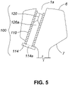
- the method generally comprises inserting the rail port insert into the rail head outlet port 1, from either the top surface 6 of the railhead 5 (see Figure 1G ), or from the undersurface 7 of the railhead 5 (see Figure 5 ), and coupling the rail port insert to the railhead outlet port.
- the rail port insert may be, for example, threadedly engaged within the railhead outlet port, it may be press-fit within the railhead outlet port, it may be tack-welded or welded within the railhead outlet port, it may be adhesively engaged with the railhead port outlet wall, or a retainer may be tightened to press the wall of the outer casing against the railhead port wall to secure the rail port insert within the railhead port.
- the rail port insert may be removed using the reverse procedure as used for installation, or the insert may be drilled out, and a new rail port insert replaced.
- the reset or chamfered edge of the railhead port opening may need to be rejuvenated periodically, for example by drilling.
- the rail port insert 100 is placed within the railhead port opening so that the top of the insert sits below or flush with, the top surface of the railhead.
- the distance from the top of the rail port insert 100 to the surface of the railhead is from about 0 to 20mm or any amount therebetween, for example, from about 0, 1, 2, 3, 4, 5, 6, 7, 8, 9, 10, 11, 12, 13, 14, 15, 16, 17, 18, 19 20mm or any amount therebetween.
- a rail port insert 100 comprising an outer casing 110 and an elastomeric body (a check valve) 120, as described above.
- the rail port insert 100 is for inserting into a railhead outlet port 1.
- the rail port insert 100 may be inserted within a railhead port 1 by inserting the rail port insert into the opening of the railhead port located on the top surface 6 of a railhead 5 as shown in Figure 1G .
- the rail port insert 100 may be inserted within a railhead port 1 by inserting an elongate rail port insert into the opening of the railhead port located on the bottom or undersurface 7 of a railhead 5 ( Figure 5 ).
- the base of the elongate rail port insert 114 may be connected to a source of a friction modifying composition or lubricant.
- the conduit of the rail port insert 1b is in fluid communication with the friction modifying composition or lubricant delivery system that supplies the friction modifying composition or lubricant from as storage location to the railhead port 1.
- the opening defined by the top of the insert 110 may comprise a reset (or chamfered edge, not shown), relative to the outer diameter 115 of the main conduit traversing the insert 110a, so that the edge is reset back from the outer diameter 115 of the conduit from about 0 to about 8mm, or any amount therebetween, for example from about 0, 0.5, 1.0, 2.0, 3.0, 4.0, 5.0, 6.0, 7.0, 8.0mm or any amount therebetween.
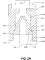
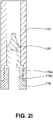
- a non-limiting example of an insert comprising an edge at the top of the insert that is reset back from the outer diameter 115 of the main conduit is shown in Figure 2H .
- the amount of reset employed may depend upon the type of train or load, being transported along the track.
- the rail port insert 100 may be comprised of the elastomeric body 120 alone, and the elastomeric body 120 press-fit into a corresponding railhead port 1 from either the top surface 6 of the railhead 5, or from the bottom, or undersurface 7 of the railhead 5.
- the elastomeric body may also be made of two or more materials, for example, a rigid outer layer that is bonded or fused to, a resilient, flexible central core, and the rigid outer layer of the rail port insert may engage with the railhead port as described below.
- the rail port insert 100 comprises an outer casing 110, which comprises an open end 112, a base 114 that is opposite the open end 112, a tubular sidewall 116 extending between the base 114 and the open end 112, and an inlet passage 114a that extends through the base 114.
- the tubular sidewall 116 and the base 114 define a spatial volume 110a.
- the outside surface 130, of sidewall 116 registers against the wall 2 of the railhead port 1 ( Figure IF) when the rail port insert is secured or fastened within a railhead, as shown in Figure 1G .
- the outer casing 110 is manufactured of a material that is suitable for withstanding repeated impact by a rail car wheel and may include, but are not limited to, a metal, a metal alloy, fiber (for example, carbon fiber or glass fiber) reinforced plastic, or a plastic.
- threaded engagements 110b circumscribe at least a portion of the outer surface 130, of the outer casing 110 (for example as shown in Figure 1A ).
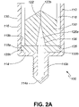
- threaded engagements 110b may circumscribe a lower portion, or extension, of the outer casing 110 as shown for example in Figure 2A .
- the threaded engagements 110b are for engaging complementary threaded engagements (not numbered) located within the railhead outlet port 1 of rail 5. If the railhead port does not comprise a complementary threaded engagement, then the existing railhead port may be modified so that a complementary threaded portion is introduced using standard procedures, for example by a tap, so that the railhead port may receive threaded engagement 110b.
- the top surface of the outer casing 110 may comprises one or more slots or openings (not shown) for receiving an insertion tool, and that may be used for installing rail port insert 100 into, or removing rail port insert 100 from, railhead outlet port 1.
- the top surface may have a slot into which an external apparatus (not shown) may register, and for example, turn insert 100 into the railhead outlet port 1 such that insert 100 threadedly engages the railhead outlet port 1.
- insert 100 may engage outlet port 1 of railhead 5 by a locking mechanism or other method known in the art, for example a C-clip, a pin, an adhesive, by press fitting an oversized insert 100 into port 1 so that a frictional engagement is established between the outside surface 130 of sidewall 116, and wall 2 of railhead outlet port 1, or a combination thereof.
- the rail port insert 100 may further comprise a portion of the sidewall that protrudes above rail when installed and that comprises flats or tabs, that are used to install or tighten the rail port insert into the railhead port. After installation, the protruding portion may be removed, for example by grinding the protruding portion flush to the railhead surface.
- elastomeric body, or check valve, 120 is made of two or more materials, for example, a rigid outer layer that is bonded or fused to, a resilient, flexible inner layer or central core, then in addition to the above mentioned attachment options, the rigid outer layer of the elastomeric body 120 may comprise threaded engagement 110b that engage corresponding threads in a railhead port 1, or the bi-layered the elastomeric body may be press-fit into railhead port 1.
- the elastomeric body 120 comprises a top surface (second end) 120a, which may be flat ( Figure 1A ), curved, comprise a recess potion ( Figure 1J ), or that may be beveled ( Figure 2A ).
- the elastomeric body further comprises a first end, or base, 120b (for example figure 2A ) and 120c ( Figure IE), and a flow passageway 126 having a length that extends from the first end 120a to the second end 120b.
- the first end is in fluid communication with the inlet passage of the base 114a, and the second end comprising a depth-length 122a, the depth-length defining orifice 122.
- the elastomeric body is made of a resilient, elastomeric material, including, but not limited to, rubber, silicone, polyurethane, high density foam, nitrile, fluorocarbon, isoprene, latex, ethylene propylene, styrene butadiene, polyacrylate, polybutadiene, polyisoprene, fluorosilicone, neoprene and the like.
- the elastomeric body may also be made of two or more materials, for example, a rigid outer layer that is bonded or fused with, a resilient, flexible central core.
- the rigid outer layer of the elastomeric body may be a rigid polymeric material or a metal.
- the elastomeric body 120 may also comprise a relief zone 120d ( Figure 1K ) that circumscribes, or partially circumscribes, the outer surface of the elastomeric body.
- the relief zone 120d may be located at any location along the outer wall of the elastomeric insert, including the top portion, mid or waist region, or bottom portion of the elastomeric insert 120.
- the relief zone 210d may be used to adjust the flexibility of the elastomeric insert in order to assist opening and closing of the orifice 122.
- a flow passageway 126 defining conduit 126a extends between the orifice 122 and the inlet 124 of the elastomeric body 120.
- the orifice 122 of the elastomeric body 120 has a closed position (for example, Figures 1A and ID) and an open position (for example Figures 1B and 1C .
- conduit 126a extends from inlet 124 to second end 122c located at the base of orifice 122.
- conduit 126a extends through the entire elastomeric body 120 from inlet 124 to first end 122b located at the top end of the orifice 122.
- conduit 126a tapers towards orifice 122.
- conduit 126a may comprise a first portion that substantially has a constant diameter, and a second portion that has a changing diameter so that the wall of flow passageway 126 is beveled towards the second end 122c located at the base of orifice 122.
- orifice 122 is in the open position, as depicted in Figure 1B , the second portion of conduit 126a extends towards the first end 122b located at the upper end of orifice 122.
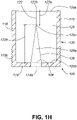
- the conduit 126a also may be beveled from inlet 124, to the second end 122c of orifice 122 (see for example, Figures 1C , 1H , 1I ), the conduit 126a may have a cross-sectional diameter that decreases from inlet 124 to the orifice 122, or conduit 126a may adopt alternate configurations, for example, it may have a stepped decreased in diameter at one or more locations along the conduit 126a.
- conduit 126 may include a general taper from base of the elastomeric body 120b to second end 122c, is presented in Figures 1H , 11 , 2A , 2C , or a recess within the elastomeric body as shown in Figures 1J and 1K .
- the orifice 122 in the closed position has a depth-length 122a.
- the ratio of the depth-length 122a to the length of the beveled conduit 122d (see Figures 1A and 1H ), when the orifice 122 is closed, may be varied to ensure dispensing of the lubricant or friction modifying material through insert 100, while at the same time minimizing evaporation of the friction modifying material or lubricant when orifice 122 is closed.
- the depth-length 122a, and the diameter of conduit 126a that is selected should permit flow of a friction control composition or lubricant, when pressure is exerted on the friction control composition or lubricant from an outside pump (via railhead conduit 1b, through conduit 126a, and out of orifice 122).
- the depth-length to length of beveled conduit ratio that is selected should, in absence of any pressure being applied to the friction control composition or lubricant, ensure that orifice 122 remains closed.
- the ratio of the depth-length 122a to the length of the beveled conduit 122d may vary depending upon the resiliency or elastic properties of the elastomeric body 120.
- the ratio of depth length 122a: length of beveled conduit 122d may be from about 1:100 to about 50:1, or any ratio therebetween.
- the ratio of depth length 122a: length of beveled conduit 122d may be from 1:100, 1:95, 1:90, 1:85, 1:80, 1:75, 1:70, 1:65, 1:60, 1:55, 1:50, 1:45, 1:40, 1:35, 1:30, 1:25, 1:20, 1:15, 1:10, 1:8, 1:6, 1:4, 1:2, 1:1, 2:1, 3:1, 4:1, 5:1, 6:1, 7:1, 8:1, 9:1, 10:1, 15:1, 20:1, 25:1, 30:1, 35:1, 40:1, 45:1, 50:1, or any ratio therebetween.
- the elastomeric body 120 may comprise a circular orifice 122, or it may comprise one or more tubular or semi circular channels arranged around a central portion of the elastomeric body 120.
- the elastomeric body 120 further comprises an umbrella valve 140 with one or more arms 140a. The arms 140a of the umbrella valve 140 are movable from a closed ( Figure 6A ) to an open ( Figure 6B ) position.
- the umbrella valve 140 may be made of the same material as the elastomeric body for example, a resilient, elastomeric material, including, but not limited to, rubber, silicone, polyurethane, high density foam, nitrile, fluorocarbon, isoprene, latex, ethylene propylene, styrene butadiene, polyacrylate, polybutadiene, polyisoprene, fluorosilicone, neoprene and the like.
- a resilient, elastomeric material including, but not limited to, rubber, silicone, polyurethane, high density foam, nitrile, fluorocarbon, isoprene, latex, ethylene propylene, styrene butadiene, polyacrylate, polybutadiene, polyisoprene, fluorosilicone, neoprene and the like.
- the umbrella valve 140 may, when viewed from a top view, be circular in shape so that the arms 140a form a continuous circular ridge around the central stem 140b of the umbrella valve 140 ( Figure 6C ).
- the umbrella valve 140 may comprise one or more arms 140a, attached to the central stem 140b, that are arranged to cover a corresponding opening of each of the one or more tubular channels ( Figure 6D ).
- the umbrella valve 140 comprises one or more arms 140a, each overlay a corresponding channel opening, and when viewed from a top view, may appear star-like in shape.
- the umbrella valve 140 may be formed so that it is integral with the elastomeric body 120, or the umbrella valve may be secured to the elastomeric body by central stem 140b.
- the elastomeric body 120 may be press fit into the spatial volume 110a of outer casing 110.
- a lateral compression force against at least a portion of the elastomeric body 120 and at least along the depth length 122a of orifice 122 is established, thereby biasing orifice 122 in the closed position.
- the body inlet 124 is fluidly communicative with outer casing inlet passage 114a.
- elastomeric body 120 may be mechanically coupled (for example by a C-clip, one or more pin, threaded attachment), adhesively coupled, or chemically bonded to outer casing 110 by methods known to one of skill in the art, provided that, when installed, a lateral compression force is exerted against the elastomeric body 120, and at least along the depth length 122a of orifice 122 is established to bias orifice 122 to the closed position when the pressure to the friction control composition or lubricant is below a certain threshold pressure, or the pressure is removed.
- elastomeric body 120 may also include an extension of base 120c that is press fit through inlet 114a and overlaps the base of casing 114 thereby retaining elastomeric body 120 within outer casing 110, provided that, when installed, a lateral compression force is exerted against the elastomeric body 120, and at least along the depth length 122a of orifice 122 is established to bias orifice 122 to the closed position when the pressure to the friction control composition or lubricant is below a certain threshold pressure, or the pressure is removed.
- Insert 100 may be threadedly engaged with the railhead outlet port 1 using threaded engagements 110b.
- elastomeric body 120 may be press fit, mechanically coupled, adhesively coupled, or chemically bonded to wall 2 of the railhead port 1, directly, without using outer casing 110.
- elastomeric body 120 is made of two or more materials, for example, a rigid outer layer that is bonded or fused to, a resilient, flexible inner layer, or central core, then the rigid outer layer of the elastomeric body 120 may, in addition to the above mentioned attachment options, comprise threaded engagement 110b, or the bi-layered elastomeric body may be press-fit into railhead port 1.
- insert 100 When fully engaged with the railhead outlet port 1, insert 100 resides within the railhead outlet port 1 and does not protrude past the mouth 1a of the railhead outlet port 1 (see Figure 1G ).
- inlet 124 and outer casing inlet passage 114a are in fluid communication with a railhead conduit 1b.
- Railhead conduit 1b is also in fluid communication with a reservoir (not shown) containing a friction modifying material or lubricant.
- friction modifying material or lubricant is directed from the reservoir, through railhead conduit 1b in rail head 5, towards the inlets 114a and 124, and enters conduit 126a.
- a first mechanism for example, but not limited to those described in WO 2011/143765 , WO2013/067628 , US 7,841,400 .
- friction modifying material or lubricant is directed from the reservoir, through railhead conduit 1b in rail head 5, towards the inlets 114a and 124, and enters conduit 126a.
- pressure is exerted against the walls of the beveled portion of conduit 126a until a compression force against the length 122a is overcome and orifice 122 is opened (see Figures 1C and ID).
- the orifice 122 is opened, the lubricant or other friction modifying material flows onto the top surface 120a of the elastomeric body 120, and becomes available for transfer to the surface of passing rail wheel.
- a rail port insert comprises, an elastomeric body having a first end and a second end, a rigid outer layer fused to a resilient, flexible central core, the elastomeric body comprising a flow passageway within the central core, the flow passageway having a length extending from the first end to the second end, the first end defining an inlet in fluid communication with the flow passageway, the second end comprising a depth-length and defining an orifice along the depth-length and in fluid communication with the flow passageway, the orifice moving from a closed position in the absence of any applied pressure within the flow passageway, to an open position when pressure is applied within the flow passageway, when the rail port insert is installed in a railhead port, the inlet is in fluid communication with a railhead conduit.
- rail port insert 100 comprising an outer casing 110, an elastomeric body 120, and a retainer 118.
- the retainer 118 functions in maintaining the elastomeric body within the outer casing 110 as described below.
- the rail port insert is similar to that as described above and comprises an outer casing 110 with an open end 112, a base 114 opposite a top end of the outer casing, sidewalls 116 extending between the base 114 and the top end of the outer casing, and an inlet passage 114a that extends through base 114 of the outer casing 210.
- the sidewalls 116 and the base 114 define a spatial volume 110a of outer casing 110.
- the outer casing 110 and the retainer 118 are manufactured of a material that is suitable for withstand repeated impact by a railroad car wheel. Materials suitable for such application include, but not limited to, a metal, a metal alloy, fiber (for example, carbon fiber or glass fiber) reinforced plastic, or a plastic.
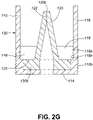
- Threaded engagements 110b may circumscribe, or partially circumscribe walls 116 (for example as shown in Figures 2F , 2G ), or the base 114 (for example as shown in Figure 2A ), of the outer casing 110, and engage complementary threaded engagements (not numbered) located within the railhead outlet port 1 of railhead 5. If the railhead port does not comprise a complementary threaded engagement, then the existing railhead port may be modified so that a complementary threaded portion is introduced, for example by a tap, to receive the threaded engagement 110b.
- outer casing 110 may engage outlet port 1 by a locking mechanism or other method known in the art, for example a C-clip, a pin, or by press fitting an oversized insert 100 into port 1 so that a frictional engagement is established between the insert 100 and the wall of port 1.
- a locking mechanism or other method known in the art for example a C-clip, a pin, or by press fitting an oversized insert 100 into port 1 so that a frictional engagement is established between the insert 100 and the wall of port 1.
- the elastomeric body 120 made of similar elastomeric materials to that as described above, for example a resilient, elastomeric material, including, but not limited to, rubber, silicone, polyurethane, high density foam, nitrile, fluorocarbon, isoprene, latex, ethylene propylene, styrene butadiene, polyacrylate, polybutadiene, polyisoprene, fluorosilicone, neoprene and the like, comprises an orifice 122, an inlet 124, a flow passageway 126 that extends between orifice 122 and inlet 124, as described above.
- a resilient, elastomeric material including, but not limited to, rubber, silicone, polyurethane, high density foam, nitrile, fluorocarbon, isoprene, latex, ethylene propylene, styrene butadiene, polyacrylate, polybutadiene, polyisoprene, fluor
- the elastomeric body 120 may be press-fit with retainer 118, so that the sides comprising orifice 122 are pressed closed when the elastomeric body 120 is inserted within retainer 118.
- the elastomeric body, or check valve, 120 may be a self-closing nozzle, such as a duckbill self-closing valve, for example as described in US 4,524,805 .
- orifice 122 of the self-closing nozzle comprises an inherent elastomeric retentive force that biases it to a closed position (see for example, Figure 2G ).
- elastomeric body 120 may comprise a circular flange at base 120b that has a larger outer diameter than the outer diameter of the main body of the elastomeric body 120 ( Figures 2A-2G ).
- the bottom portion of the retainer 118 fits against an upper surface of the circular flange 125 of the elastomeric body 120.
- the elastomeric body 120 is placed within retainer 118, and the retainer is inserted within outer casing 110, the elastomeric body 120 is secured within the outer casing 110 by retainer 118 at circular flange 125.
- elastomeric body 120 In use, elastomeric body 120, or the self-closing nozzle, is inserted into retainer 118 so that the upper surface of circular flange 125 fits against the base of retainer 118.
- the retainer fitted with the elastomeric body are then inserted into the spatial volume 110a of outer casing 110.
- threaded engagements 118a circumscribe at least a portion of the inner surface of the sidewall 116 of the outer casing 110
- complementary threaded engagements 118b circumscribe at least a portion of the outer surface of the retainer 118.
- Threaded engagements 118a and complementary threaded engagements 118b mate to secure retainer 118 within the spatial volume 110a of outer casing 110.
- the body inlet 124 is in fluid communication with outer casing inlet passage 114a.
- Retainer 118 may also engage outer casing 110 by a locking mechanism or other method known in the art, for example a C-clip, a pin, or by press fitting an oversized retainer 118 into outer casing 110 so that a frictional engagement is established between the retainer 118 and wall 116.
- rail port insert 100 comprises an outer casing 110 that is characterized as having a beveled inner surface 119 that forms an inverted cone ( Figure 2D ), a retainer 118 having beveled outer surface 119a forms a conical shape for matingly engaging the inverted cone of the outer casing 110, and an elastomeric body 120.
- the elastomeric body 120 may have an orifice 122 that is pressed closed as a result of engagement with walls of retainer 118, or it may be a self-closing nozzle, such as a duckbill self-closing valve, for example as described in US 4,524,805 .
- Threaded engagements 118b circumscribe, or partially circumscribe the base of retainer 118.
- the threaded engagements 118b engage complementary threaded engagements 118a of the inner wall 119 of the outer casing 110.
- the rail port insert 100 as shown in Figure 2C is placed within the railhead outlet port 1 of rail 5 and the retainer 118 is secured to the outer casing 110 by engaging threaded engagements 118b and 118a.
- the retainer 118 is threaded into outer casing 110, the beveled outer wall 119a, of retainer 118, presses against the beveled inner wall 119 of the outer casing 110, and forces outer wall 130, of outer casing 110, against the wall 2 of the railhead outlet port 1, thereby securing retainer 118 to the outer casing 110, and the rail port insert 100 to the railhead outlet port 1.
- the rail port insert 100 may be removed from railhead port 1 by reversing these steps.
- the rail port insert 100 may further comprise a portion of the sidewall that protrudes above rail when installed and that comprises flats, or tabs that are used to install or tighten the rail port insert into the railhead port. After installation, the protruding portion may be removed, for example by grinding the protruding portion flush to the railhead surface.
- orifice 122 When elastomeric body 120 is fully inserted within retainer 118, and engaged with outer casing 110, orifice 122 may reside within the spatial volume 110a so that top of orifice, 122b, resides below a plane defined by the top end of wall 116 of outer casing 110 that would be flush with the rail head surface when the rail port insert 100 is placed within the rail port 1 of the rail head 5, for example, as shown in Figure 2A .
- the inner wall of retainer 118 may include an extension, for example a ring or flange 135 ( Figures 2E , 2H ) that circumscribes the inner wall of sidewall 116.
- the ring 135 may comprise an inclination on its undersurface that is complementary to the inclined top surfaces of elastomeric body 120.
- Flange 135 may be formed as part of the retainer as shown in Figure 2E , or flange 135 may be made of a different material and adhesively attached or mechanically coupled to the inner wall of the retainer 118.
- flange 135 may include threads on its outer wall that engage with threads located at the top of the inner wall of retainer 118.
- Flange 135 may be made of the same material as the retainer, or it may be made from a rubber or polyurethane, silicone, material or a similar manner to that of the elastomeric insert.
- the top surface of the elastomeric body may be positioned so that it is flush with the rail head surface when the rail port insert 100 is placed within the rail port 1 of the rail head 5, in a manner analogous to that shown in Figures 1C, 1D or 2F .
- the elastomeric body 120 may comprise a circular flange 125 at base 120b that fits against flange 117 of inner wall of sidewall 116 ( Figure 2H , 21 ).
- the elastomeric body 120 or self closing nozzle, is inserted within the outer casing of the insert 110, the top surface of the flange 125 of the elastomeric body 120 fits against the bottom surface of a flange 117 of an inner wall of side wall 116 of the outer casing 110, and retainer 118 is engaged with the outer casing 110 so that the top surface of the retainer 118 fits against a bottom surface 120b of the elastomeric body 120.
- threaded engagements 118a circumscribe at least a portion of the inner surface of the sidewall 116 of the outer casing 110
- complementary threaded engagements 118b circumscribe at least a portion of the outer surface of the retainer 118. Threaded engagements 118a and complementary threaded engagements 118b mate to secure retainer 118 to the outer casing 110.
- Retainer 118 may also engage outer casing 110 by a locking mechanism or other method known in the art, for example a C-clip, a pin, or by press fitting an oversized retainer 118 into outer casing 110 so that a frictional engagement is established between the retainer 118 and wall 116.
- a locking mechanism or other method known in the art for example a C-clip, a pin, or by press fitting an oversized retainer 118 into outer casing 110 so that a frictional engagement is established between the retainer 118 and wall 116.
- the opening 112 defined by the top of the insert 110 may comprise a reset (or chamfered edge, not shown), relative to the outer diameter 115 of the main conduit traversing the insert 110a, so that the edge is reset back from the outer diameter 115 of the conduit from about 0 to about 8mm, or any amount therebetween, for example from about 0, 0.5, 1.0, 2.0, 3.0, 4.0, 5.0, 6.0, 7.0, 8.0mm or any amount therebetween.
- the reset opening of the outer casing may be drilled out as required to remove any flanged, lipped or deformed edges during regular maintenance.
- inlet 124 of rail port insert 100, and inlet 114a are fluidly communicative with railhead conduit 1b ( Figure 1G ).
- Conduit 1b is connected to a reservoir (not shown) that stores lubricant or other friction modifying material.
- friction modifying material or lubricant is directed from the reservoir, through railhead conduit 1b in rail head 5, towards the inlets 114a and 124, and enters conduit 126a.
- a first mechanism for example, but not limited to those described in WO 2011/143765 , WO2013/067628 , US 7,841,400
- friction modifying material or lubricant is directed from the reservoir, through railhead conduit 1b in rail head 5, towards the inlets 114a and 124, and enters conduit 126a.
- pressure is exerted against the walls of the beveled portion of conduit 126a, or a self-closing nozzle (for example as described in US 4,524,805 ), until orifice 122 is opened.
- the lubricant or other friction modifying material flows onto the top surface 120a of the elastomeric body 120, and becomes available for transfer to the surface of passing rail wheel.
- a second mechanism known in the art for example but not limited to those described in WO 2011/143765 , WO2013/067628 , US 7,841,400 , the flow of lubricant or other friction modifying material through the conduit 126a is reduced and the pressure against the walls of the beveled portion of conduit 126a, or self-closing nozzle, decreases.
- a rail port insert comprises, an outer casing comprising a tubular sidewall and a base, the sidewall and base defining a spatial volume therein, the base defining an inlet passage that extends through the base and that is fluid communication with the spatial volume, a tubular retainer that is disposed within the spatial volume so that an outer wall of the retainer is affixed to an inner surface of the tubular sidewall, the tubular retainer defining an open top end and an open bottom end, an elastomeric body having a first end and a second end, the elastomeric body comprising a circular flange at the first end, the circular flange having an upper surface and a lower surface, the elastomeric body disposed within the retainer so that the upper surface of the circular flange sits against the bottom end of the retainer, and the lower surface of the circular flange sits against the base, the elastomeric body comprising a flow passageway having a length extending from the first end to
Landscapes
- Engineering & Computer Science (AREA)
- Mechanical Engineering (AREA)
- Fuel-Injection Apparatus (AREA)
- Gasket Seals (AREA)
- Valve Housings (AREA)
- Quick-Acting Or Multi-Walled Pipe Joints (AREA)
Claims (15)
- Schienenanschluss-Einsatz (100) umfassend:
einen Elastomerkörper (120), der ein erstes Ende (120a) und ein zweites Ende (120b) aufweist, wobei der Elastomerkörper (120) einen Strömungsdurchgang (126) umfasst, der sich von dem ersten Ende (120a) zu dem zweiten Ende (120b) erstreckt, wobei das erste Ende (120a) einen Einlass (124) in Fluidverbindung mit dem Strömungsdurchgang (126) definiert, wobei das zweite Ende (120b) eine Tiefenlänge (122b) umfasst und eine Öffnung (122) entlang der Tiefenlänge (122b) und in Fluidverbindung mit dem Strömungsdurchgang (126) definiert, und wobei die Öffnung (122) sich von einer geschlossenen Position bei Abwesenheit jeglichen angelegten Drucks innerhalb des Strömungsdurchgangs (126) in eine offene Position bewegt, wenn Druck innerhalb des Strömungsdurchgangs (126) angelegt wird, so dass, wenn der Schienenanschluss-Einsatz (100) in einen Schienenkopf-Anschluss (1) eingesetzt ist, der Einlass (124) in Fluidverbindung mit einer Schienenkopf-Rohrleitung (1b) steht. - Schienenanschluss-Einsatz (100) nach Anspruch 1, wobei zumindest ein Teil des Strömungsdurchgangs (126) von dem ersten Ende (120a) zu dem zweiten Ende (120b) abgeschrägt ist, so dass, wenn sich die Öffnung (122) in der geschlossenen Position befindet, eine abgeschrägte Leitung (122d) gebildet wird, die eine abgeschrägte Länge aufweist, die sich von dem ersten Ende (120a) zu einem Boden der Tiefenlänge (122b) erstreckt.
- Schienenanschluss-Einsatz (100) nach Anspruch 2, wobei, wenn sich die Öffnung (122) in der geschlossenen Position befindet, das Verhältnis von Tiefenlänge (122b) zu abgeschrägter Länge etwa 1:100 bis etwa 50:1 beträgt.
- Schienenanschluss-Einsatz (100) nach einem der Ansprüche 1 bis 3, wobei der Elastomerkörper (120) des Weiteren eine starre Außenschicht umfasst, die mit einem elastischen, flexiblen Mittelkern verschmolzen ist, wobei sich der Strömungsdurchgang (126) innerhalb des Mittelkerns befindet.
- Schienenanschluss-Einsatz (100) nach einem der Ansprüche 1 bis 3, des Weiteren umfassend ein Außengehäuse (110), das eine rohrförmige Seitenwand (116) und eine Basis (114) umfasst, wobei die Seitenwand (116) und die Basis (114) ein Raumvolumen (110a) darin definieren, wobei die Basis einen Einlassdurchgang (114a) definiert, der sich durch die Basis (114) erstreckt und der in Fluidverbindung mit dem Raumvolumen (110a) steht, wobei der Elastomerkörper (120) innerhalb des Raumvolumens (110a) angeordnet und an einer Innenfläche der rohrförmigen Seitenwand (116), an der Basis (114) oder sowohl an einer Innenfläche der rohrförmigen Seitenwand (116) als auch an der Basis (114) befestigt ist, wobei der Einlass (124) des ersten Endes (120a) in Fluidverbindung mit dem Einlassdurchgang (114a) der Basis (114) steht, und wobei, wenn der Schienenanschluss-Einsatz (100) in dem Schienenkopf-Anschluss (1) eingesetzt ist, der Einlassdurchgang (114a) des Außengehäuses (110) in Fluidverbindung mit der Schienenkopf-Rohrleitung (1b) steht.
- Schienenanschluss-Einsatz (100) nach Anspruch 5, wobei das Außengehäuse (110) einen Gewindeeingriff (110b) umfasst, der zumindest einen Teil einer Außenfläche der rohrförmigen Seitenwand (116) umschreibt.
- Schienenanschluss-Einsatz (100) nach Anspruch 5, wobei der Elastomerkörper (120) in die Innenfläche der rohrförmigen Seitenwand (116) eingepresst ist.
- Schienenanschluss-Einsatz (100) nach Anspruch 5, wobei der Elastomerkörper (120) eine Verlängerung an dem zweiten Ende (120b) umfasst, wobei die Verlängerung durch eine Bodenfläche der Basis (114) verläuft und diese überlappt.
- Schienenanschluss-Einsatz (100) nach einem der Ansprüche 5 bis 8, wobei der Schienenanschluss-Einsatz (100) des Weiteren einen Halter (118) umfasst, der innerhalb des Raumvolumens (110a) angeordnet ist, so dass eine Außenwand des Halters (118) an einer Innenfläche der rohrförmigen Seitenwand (116) befestigt ist, wobei der Halter (118) ein offenes oberes Ende und ein offenes unteres Ende definiert, wobei der Elastomerkörper (120) einen kreisförmigen Flansch (125) an dem ersten Ende (120a) umfasst, wobei der kreisförmige Flansch (125) eine obere Fläche und eine untere Fläche aufweist, so dass:i) der Elastomerkörper (120) innerhalb des Halters (118) so angeordnet ist, dass die obere Fläche des kreisförmigen Flansches (125) an dem unteren Ende des Halters (118) anliegt und die untere Fläche des kreisförmigen Flansches (125) an der Basis (114) anliegt, oderii) der Elastomerkörper (120) innerhalb des Raumvolumens (110a) so angeordnet ist, dass die obere Fläche des kreisförmigen Flansches (125) an einem Flansch anliegt, der an einer Innenwand des Außengehäuses (110) positioniert ist, und die untere Fläche des kreisförmigen Flansches (125) an dem oberen Ende des Halters (118) anliegt.
- Schienenanschluss-Einsatz (100) nach Anspruch 9, wobei der Halter (118) so eingepresst ist, dass die Außenwand des Halters (118) reibschlüssig in die Innenfläche der rohrförmigen Seitenwand (116) des Außengehäuses (110) eingreift, oder der Halter (118) einen Gewindeeingriff (118b) an einer Außenfläche umfasst, und das Außengehäuse einen entsprechenden Gewindeeingriff (118a) umfasst, der zumindest einen Teil der Innenfläche der rohrförmigen Seitenwand (116) umschreibt.
- Schienenanschluss-Einsatz (100) nach Anspruch 10, wobei der Halter (118) konisch geformt ist und die Außenfläche (119a) des Halters (118) von dem oberen Ende zu dem unteren Ende hin abgeschrägt ist, und die Innenfläche (119) der rohrförmigen Seitenwand (116) abgeschrägt ist, wodurch ein umgekehrter Konus gebildet wird, der mit der Außenfläche des Halters (118) zusammenpasst.
- Schienenanschluss-Einsatz (100) nach Anspruch 9, wobei eine Innenwand an dem oberen Ende des Halters (118) des Weiteren einen kreisförmigen Flansch (135) umfasst, der sich in Richtung einer Mitte des Halters (118) erstreckt, wobei der Flansch eine Öffnung definiert, die sich oberhalb der Öffnung (122) befindet.
- Schienenanschluss-Einsatz (100) nach einem der Ansprüche 1 bis 12, der des Weiteren ein Schirmventil (140) umfasst, das an dem zweiten Ende (120b) angebracht ist, wobei sich das Schirmventil (140) von einer geschlossenen Position bei Abwesenheit jeglichen angelegten Drucks innerhalb des Strömungsdurchgangs (126) in eine offene Position bewegt, wenn innerhalb des Strömungsdurchgangs (126) Druck anliegt.
- Verfahren zum Einsetzen des Schienenanschluss-Einsatzes (100) nach einem der Ansprüche 1 bis 13 in einen Schienenkopf-Auslassanschluss (1), umfassend das Einsetzen des Schienenanschluss-Einsatzes (100) in den Schienenkopf-Auslassanschluss (1); und das Verbinden des Schienenanschluss-Einsatzes (100) mit dem Schienenkopf-Auslassanschluss (1).
- Verfahren nach Anspruch 14, wobei in dem Schritt des Verbindens der Schienenanschluss-Einsatz (100) innerhalb des Schienenkopf-Auslassanschlusses (1) in Gewindeeingriff gebracht wird.
Applications Claiming Priority (1)
| Application Number | Priority Date | Filing Date | Title |
|---|---|---|---|
| PCT/CA2016/050834 WO2018010001A1 (en) | 2016-07-14 | 2016-07-14 | Rail port insert |
Publications (3)
| Publication Number | Publication Date |
|---|---|
| EP3484757A1 EP3484757A1 (de) | 2019-05-22 |
| EP3484757A4 EP3484757A4 (de) | 2020-03-25 |
| EP3484757B1 true EP3484757B1 (de) | 2022-07-06 |
Family
ID=60952242
Family Applications (1)
| Application Number | Title | Priority Date | Filing Date |
|---|---|---|---|
| EP16908369.8A Active EP3484757B1 (de) | 2016-07-14 | 2016-07-14 | Schienenöffnungseinsatz |
Country Status (4)
| Country | Link |
|---|---|
| US (1) | US11155284B2 (de) |
| EP (1) | EP3484757B1 (de) |
| CA (1) | CA3030365C (de) |
| WO (1) | WO2018010001A1 (de) |
Families Citing this family (1)
| Publication number | Priority date | Publication date | Assignee | Title |
|---|---|---|---|---|
| EP3484757B1 (de) * | 2016-07-14 | 2022-07-06 | L.B. Foster Rail Technologies, Corp. | Schienenöffnungseinsatz |
Family Cites Families (29)
| Publication number | Priority date | Publication date | Assignee | Title |
|---|---|---|---|---|
| US1883148A (en) * | 1928-10-11 | 1932-10-18 | Maintenance Equipment Company | Wheel flange oiler |
| US1800464A (en) * | 1928-12-01 | 1931-04-14 | Metz Emil George | Rail-oiling device |
| US1977755A (en) * | 1930-05-08 | 1934-10-23 | William H Foster | Flange and rail lubricator |
| US2272774A (en) * | 1939-01-27 | 1942-02-10 | John T Mcgarry | Rail lubricator |
| US2272775A (en) * | 1939-02-20 | 1942-02-10 | John T Mcgarry | Wheel flange and rail lubricator |
| US3051262A (en) * | 1959-11-20 | 1962-08-28 | Railroad Accessorics Corp | Apparatus for reducing friction between railroad car wheels and rails |
| US4067414A (en) * | 1976-08-18 | 1978-01-10 | Funke Ludwig F | Lubricant fitting |
| US4214647A (en) | 1978-02-24 | 1980-07-29 | Lutts William M | Automatic rail greasing apparatus |
| DE7930282U1 (de) | 1979-10-25 | 1980-04-10 | Radermacher, Andreas, 5376 Nettersheim | Fahrschiene mit bohrungen zur zufuhr von schmiermitteln |
| US4524805A (en) | 1983-07-08 | 1985-06-25 | Hoffman Allan C | Normally closed duckbill valve and method of manufacture |
| US5722509A (en) * | 1996-05-14 | 1998-03-03 | Consolidated Rail Corporation | Flange oiler |
| CA2186419C (en) | 1996-09-25 | 2003-12-30 | Kelvin Spencer Chiddick | Solid lubricants & friction modifiers for heavy loads and rail applications |
| US6971479B1 (en) | 1999-04-08 | 2005-12-06 | Portec Rail Products, Inc. | Top of rail applicator |
| US7244695B2 (en) | 2000-09-29 | 2007-07-17 | Kelsan Technologies Corp. | Method for reducing wear of steel elements in sliding-rolling contact |
| CN100439481C (zh) | 2000-09-29 | 2008-12-03 | 凯尔桑技术公司 | 摩擦调节组合物 |
| US6855673B2 (en) | 2002-11-08 | 2005-02-15 | Kelsan Technologies Corporation | Freeze tolerant friction control compositions |
| US6578669B2 (en) | 2001-04-27 | 2003-06-17 | Lubriquip, Inc. | Rail lubrication system |
| US6742624B2 (en) | 2002-01-29 | 2004-06-01 | Lincoln Industrial Corporation | Railroad rail lubricating apparatus |
| US6759372B2 (en) | 2002-04-12 | 2004-07-06 | Kelsan Technologies Corp. | Friction control composition with enhanced retentivity |
| SI21735B (sl) * | 2004-03-23 | 2013-05-31 | Bojan PAVÄŚNIK | Postopek in naprava za zmanjĺ evanje rebriäśenja tirnic, hrupa in zniĺ˝evanja trenja med kolesom in tirnico |
| US7160378B2 (en) | 2004-08-13 | 2007-01-09 | Kelsan Technologies Corp. | Modified friction control compositions |
| CA2622561C (en) | 2007-02-21 | 2015-09-29 | Portec Rail Products, Inc. | Grease guide |
| EP1980554A1 (de) | 2007-04-12 | 2008-10-15 | Bayer CropScience Aktiengesellschaft | 4-(3-Aminobenzoyl)-1-ehtylpyrazole und ihre Verwendung als Herbizide |
| US8584804B2 (en) | 2007-06-27 | 2013-11-19 | Lincoln Industrial Corporation | Apparatus for applying a pumpable material to a rail head |
| US7841400B2 (en) | 2008-09-05 | 2010-11-30 | Thrubit B.V. | Apparatus and system to allow tool passage ahead of a bit |
| US8955645B2 (en) | 2009-05-29 | 2015-02-17 | L.B. Foster Rail Technologies, Inc. | Top of rail foam bar |
| US8473128B2 (en) | 2010-05-19 | 2013-06-25 | L.B. Foster Rail Technologies Canada, Ltd. | Optimizing rail track performance |
| WO2011143765A1 (en) | 2010-05-19 | 2011-11-24 | Portec Rail Products, Inc. | Wayside friction management system |
| EP3484757B1 (de) * | 2016-07-14 | 2022-07-06 | L.B. Foster Rail Technologies, Corp. | Schienenöffnungseinsatz |
-
2016
- 2016-07-14 EP EP16908369.8A patent/EP3484757B1/de active Active
- 2016-07-14 US US16/317,425 patent/US11155284B2/en active Active
- 2016-07-14 CA CA3030365A patent/CA3030365C/en active Active
- 2016-07-14 WO PCT/CA2016/050834 patent/WO2018010001A1/en not_active Ceased
Also Published As
| Publication number | Publication date |
|---|---|
| WO2018010001A1 (en) | 2018-01-18 |
| EP3484757A4 (de) | 2020-03-25 |
| US11155284B2 (en) | 2021-10-26 |
| CA3030365C (en) | 2023-09-19 |
| CA3030365A1 (en) | 2018-01-18 |
| EP3484757A1 (de) | 2019-05-22 |
| US20190322297A1 (en) | 2019-10-24 |
Similar Documents
| Publication | Publication Date | Title |
|---|---|---|
| US9096242B2 (en) | Gauge face lubrication | |
| EP2435284B1 (de) | Schienenschaumstoffbalken | |
| WO2005084815A3 (en) | Nozzle with two channels for creating a water wall and a fine mist | |
| US10358153B2 (en) | Top of rail foam bar | |
| EP1911525A4 (de) | Ausstossbehälter | |
| CA2697478A1 (en) | Tapered bearing assembly cover plate and well drilling equipment comprising same | |
| CA3030365C (en) | Rail port insert | |
| KR102462566B1 (ko) | 액체 분배 모듈 | |
| US20160368016A1 (en) | Jetting dispenser, and a method for jetting droplets of fluid material | |
| US20150083828A1 (en) | Lawn sprinkler flow control device | |
| US2489182A (en) | Railway track lubricating device | |
| US2050659A (en) | Lawn sprinkler | |
| JP2004347117A (ja) | 統合圧力逃し弁を備えるマニホルド | |
| EP1118466A3 (de) | Flüssigkeitsausstosskopf | |
| US2296365A (en) | Lubricating device | |
| KR102398525B1 (ko) | 매립형 팝업노즐장치 | |
| JP4492865B2 (ja) | 定量噴出式エアゾール容器 | |
| EP3659895A1 (de) | Verbesserter oberteil eines schienenoberkantenapplikators | |
| ATE409253T1 (de) | Sanitäre auslaufarmatur | |
| US2018518A (en) | Flange and rail lubricator | |
| WO2005086948A3 (en) | Fluid dispensing methods, systems and devices | |
| JPH10258137A (ja) | 加圧開放弁 | |
| JPS583669A (ja) | 液体分配装置 | |
| WO2018021978A1 (en) | Rail head lubrication borehole and method for supplying of lubricant to rail head |
Legal Events
| Date | Code | Title | Description |
|---|---|---|---|
| STAA | Information on the status of an ep patent application or granted ep patent |
Free format text: STATUS: THE INTERNATIONAL PUBLICATION HAS BEEN MADE |
|
| PUAI | Public reference made under article 153(3) epc to a published international application that has entered the european phase |
Free format text: ORIGINAL CODE: 0009012 |
|
| STAA | Information on the status of an ep patent application or granted ep patent |
Free format text: STATUS: REQUEST FOR EXAMINATION WAS MADE |
|
| 17P | Request for examination filed |
Effective date: 20190129 |
|
| AK | Designated contracting states |
Kind code of ref document: A1 Designated state(s): AL AT BE BG CH CY CZ DE DK EE ES FI FR GB GR HR HU IE IS IT LI LT LU LV MC MK MT NL NO PL PT RO RS SE SI SK SM TR |
|
| AX | Request for extension of the european patent |
Extension state: BA ME |
|
| RIN1 | Information on inventor provided before grant (corrected) |
Inventor name: ELVIDGE, DAVID Inventor name: VANDERMAREL, JOEL |
|
| DAV | Request for validation of the european patent (deleted) | ||
| DAX | Request for extension of the european patent (deleted) | ||
| A4 | Supplementary search report drawn up and despatched |
Effective date: 20200221 |
|
| RIC1 | Information provided on ipc code assigned before grant |
Ipc: B61K 13/02 20060101ALI20200217BHEP Ipc: B61K 3/00 20060101AFI20200217BHEP |
|
| GRAP | Despatch of communication of intention to grant a patent |
Free format text: ORIGINAL CODE: EPIDOSNIGR1 |
|
| STAA | Information on the status of an ep patent application or granted ep patent |
Free format text: STATUS: GRANT OF PATENT IS INTENDED |
|
| INTG | Intention to grant announced |
Effective date: 20211130 |
|
| GRAJ | Information related to disapproval of communication of intention to grant by the applicant or resumption of examination proceedings by the epo deleted |
Free format text: ORIGINAL CODE: EPIDOSDIGR1 |
|
| STAA | Information on the status of an ep patent application or granted ep patent |
Free format text: STATUS: REQUEST FOR EXAMINATION WAS MADE |
|
| INTC | Intention to grant announced (deleted) | ||
| GRAP | Despatch of communication of intention to grant a patent |
Free format text: ORIGINAL CODE: EPIDOSNIGR1 |
|
| STAA | Information on the status of an ep patent application or granted ep patent |
Free format text: STATUS: GRANT OF PATENT IS INTENDED |
|
| INTG | Intention to grant announced |
Effective date: 20220225 |
|
| GRAS | Grant fee paid |
Free format text: ORIGINAL CODE: EPIDOSNIGR3 |
|
| GRAA | (expected) grant |
Free format text: ORIGINAL CODE: 0009210 |
|
| STAA | Information on the status of an ep patent application or granted ep patent |
Free format text: STATUS: THE PATENT HAS BEEN GRANTED |
|
| AK | Designated contracting states |
Kind code of ref document: B1 Designated state(s): AL AT BE BG CH CY CZ DE DK EE ES FI FR GB GR HR HU IE IS IT LI LT LU LV MC MK MT NL NO PL PT RO RS SE SI SK SM TR |
|
| REG | Reference to a national code |
Ref country code: AT Ref legal event code: REF Ref document number: 1502683 Country of ref document: AT Kind code of ref document: T Effective date: 20220715 Ref country code: CH Ref legal event code: EP |
|
| REG | Reference to a national code |
Ref country code: DE Ref legal event code: R096 Ref document number: 602016073434 Country of ref document: DE |
|
| REG | Reference to a national code |
Ref country code: IE Ref legal event code: FG4D |
|
| REG | Reference to a national code |
Ref country code: SE Ref legal event code: TRGR |
|
| REG | Reference to a national code |
Ref country code: LT Ref legal event code: MG9D |
|
| REG | Reference to a national code |
Ref country code: NL Ref legal event code: MP Effective date: 20220706 |
|
| PG25 | Lapsed in a contracting state [announced via postgrant information from national office to epo] |
Ref country code: RS Free format text: LAPSE BECAUSE OF FAILURE TO SUBMIT A TRANSLATION OF THE DESCRIPTION OR TO PAY THE FEE WITHIN THE PRESCRIBED TIME-LIMIT Effective date: 20220706 Ref country code: PT Free format text: LAPSE BECAUSE OF FAILURE TO SUBMIT A TRANSLATION OF THE DESCRIPTION OR TO PAY THE FEE WITHIN THE PRESCRIBED TIME-LIMIT Effective date: 20221107 Ref country code: NO Free format text: LAPSE BECAUSE OF FAILURE TO SUBMIT A TRANSLATION OF THE DESCRIPTION OR TO PAY THE FEE WITHIN THE PRESCRIBED TIME-LIMIT Effective date: 20221006 Ref country code: NL Free format text: LAPSE BECAUSE OF FAILURE TO SUBMIT A TRANSLATION OF THE DESCRIPTION OR TO PAY THE FEE WITHIN THE PRESCRIBED TIME-LIMIT Effective date: 20220706 Ref country code: LV Free format text: LAPSE BECAUSE OF FAILURE TO SUBMIT A TRANSLATION OF THE DESCRIPTION OR TO PAY THE FEE WITHIN THE PRESCRIBED TIME-LIMIT Effective date: 20220706 Ref country code: LT Free format text: LAPSE BECAUSE OF FAILURE TO SUBMIT A TRANSLATION OF THE DESCRIPTION OR TO PAY THE FEE WITHIN THE PRESCRIBED TIME-LIMIT Effective date: 20220706 Ref country code: FI Free format text: LAPSE BECAUSE OF FAILURE TO SUBMIT A TRANSLATION OF THE DESCRIPTION OR TO PAY THE FEE WITHIN THE PRESCRIBED TIME-LIMIT Effective date: 20220706 Ref country code: ES Free format text: LAPSE BECAUSE OF FAILURE TO SUBMIT A TRANSLATION OF THE DESCRIPTION OR TO PAY THE FEE WITHIN THE PRESCRIBED TIME-LIMIT Effective date: 20220706 |
|
| REG | Reference to a national code |
Ref country code: AT Ref legal event code: MK05 Ref document number: 1502683 Country of ref document: AT Kind code of ref document: T Effective date: 20220706 |
|
| PG25 | Lapsed in a contracting state [announced via postgrant information from national office to epo] |
Ref country code: PL Free format text: LAPSE BECAUSE OF FAILURE TO SUBMIT A TRANSLATION OF THE DESCRIPTION OR TO PAY THE FEE WITHIN THE PRESCRIBED TIME-LIMIT Effective date: 20220706 Ref country code: IS Free format text: LAPSE BECAUSE OF FAILURE TO SUBMIT A TRANSLATION OF THE DESCRIPTION OR TO PAY THE FEE WITHIN THE PRESCRIBED TIME-LIMIT Effective date: 20221106 Ref country code: HR Free format text: LAPSE BECAUSE OF FAILURE TO SUBMIT A TRANSLATION OF THE DESCRIPTION OR TO PAY THE FEE WITHIN THE PRESCRIBED TIME-LIMIT Effective date: 20220706 Ref country code: GR Free format text: LAPSE BECAUSE OF FAILURE TO SUBMIT A TRANSLATION OF THE DESCRIPTION OR TO PAY THE FEE WITHIN THE PRESCRIBED TIME-LIMIT Effective date: 20221007 |
|
| REG | Reference to a national code |
Ref country code: CH Ref legal event code: PL |
|
| REG | Reference to a national code |
Ref country code: BE Ref legal event code: MM Effective date: 20220731 |
|
| REG | Reference to a national code |
Ref country code: DE Ref legal event code: R097 Ref document number: 602016073434 Country of ref document: DE |
|
| PG25 | Lapsed in a contracting state [announced via postgrant information from national office to epo] |
Ref country code: SM Free format text: LAPSE BECAUSE OF FAILURE TO SUBMIT A TRANSLATION OF THE DESCRIPTION OR TO PAY THE FEE WITHIN THE PRESCRIBED TIME-LIMIT Effective date: 20220706 Ref country code: RO Free format text: LAPSE BECAUSE OF FAILURE TO SUBMIT A TRANSLATION OF THE DESCRIPTION OR TO PAY THE FEE WITHIN THE PRESCRIBED TIME-LIMIT Effective date: 20220706 Ref country code: MC Free format text: LAPSE BECAUSE OF FAILURE TO SUBMIT A TRANSLATION OF THE DESCRIPTION OR TO PAY THE FEE WITHIN THE PRESCRIBED TIME-LIMIT Effective date: 20220706 Ref country code: LU Free format text: LAPSE BECAUSE OF NON-PAYMENT OF DUE FEES Effective date: 20220714 Ref country code: LI Free format text: LAPSE BECAUSE OF NON-PAYMENT OF DUE FEES Effective date: 20220731 Ref country code: DK Free format text: LAPSE BECAUSE OF FAILURE TO SUBMIT A TRANSLATION OF THE DESCRIPTION OR TO PAY THE FEE WITHIN THE PRESCRIBED TIME-LIMIT Effective date: 20220706 Ref country code: CZ Free format text: LAPSE BECAUSE OF FAILURE TO SUBMIT A TRANSLATION OF THE DESCRIPTION OR TO PAY THE FEE WITHIN THE PRESCRIBED TIME-LIMIT Effective date: 20220706 Ref country code: CH Free format text: LAPSE BECAUSE OF NON-PAYMENT OF DUE FEES Effective date: 20220731 Ref country code: AT Free format text: LAPSE BECAUSE OF FAILURE TO SUBMIT A TRANSLATION OF THE DESCRIPTION OR TO PAY THE FEE WITHIN THE PRESCRIBED TIME-LIMIT Effective date: 20220706 |
|
| PLBE | No opposition filed within time limit |
Free format text: ORIGINAL CODE: 0009261 |
|
| STAA | Information on the status of an ep patent application or granted ep patent |
Free format text: STATUS: NO OPPOSITION FILED WITHIN TIME LIMIT |
|
| PG25 | Lapsed in a contracting state [announced via postgrant information from national office to epo] |
Ref country code: SK Free format text: LAPSE BECAUSE OF FAILURE TO SUBMIT A TRANSLATION OF THE DESCRIPTION OR TO PAY THE FEE WITHIN THE PRESCRIBED TIME-LIMIT Effective date: 20220706 Ref country code: EE Free format text: LAPSE BECAUSE OF FAILURE TO SUBMIT A TRANSLATION OF THE DESCRIPTION OR TO PAY THE FEE WITHIN THE PRESCRIBED TIME-LIMIT Effective date: 20220706 Ref country code: BE Free format text: LAPSE BECAUSE OF NON-PAYMENT OF DUE FEES Effective date: 20220731 |
|
| 26N | No opposition filed |
Effective date: 20230411 |
|
| P01 | Opt-out of the competence of the unified patent court (upc) registered |
Effective date: 20230509 |
|
| GBPC | Gb: european patent ceased through non-payment of renewal fee |
Effective date: 20221006 |
|
| PG25 | Lapsed in a contracting state [announced via postgrant information from national office to epo] |
Ref country code: AL Free format text: LAPSE BECAUSE OF FAILURE TO SUBMIT A TRANSLATION OF THE DESCRIPTION OR TO PAY THE FEE WITHIN THE PRESCRIBED TIME-LIMIT Effective date: 20220706 |
|
| PG25 | Lapsed in a contracting state [announced via postgrant information from national office to epo] |
Ref country code: IE Free format text: LAPSE BECAUSE OF NON-PAYMENT OF DUE FEES Effective date: 20220714 |
|
| PG25 | Lapsed in a contracting state [announced via postgrant information from national office to epo] |
Ref country code: SI Free format text: LAPSE BECAUSE OF FAILURE TO SUBMIT A TRANSLATION OF THE DESCRIPTION OR TO PAY THE FEE WITHIN THE PRESCRIBED TIME-LIMIT Effective date: 20220706 |
|
| PG25 | Lapsed in a contracting state [announced via postgrant information from national office to epo] |
Ref country code: GB Free format text: LAPSE BECAUSE OF NON-PAYMENT OF DUE FEES Effective date: 20221006 |
|
| PG25 | Lapsed in a contracting state [announced via postgrant information from national office to epo] |
Ref country code: IT Free format text: LAPSE BECAUSE OF FAILURE TO SUBMIT A TRANSLATION OF THE DESCRIPTION OR TO PAY THE FEE WITHIN THE PRESCRIBED TIME-LIMIT Effective date: 20220706 |
|
| PG25 | Lapsed in a contracting state [announced via postgrant information from national office to epo] |
Ref country code: HU Free format text: LAPSE BECAUSE OF FAILURE TO SUBMIT A TRANSLATION OF THE DESCRIPTION OR TO PAY THE FEE WITHIN THE PRESCRIBED TIME-LIMIT; INVALID AB INITIO Effective date: 20160714 |
|
| PG25 | Lapsed in a contracting state [announced via postgrant information from national office to epo] |
Ref country code: MK Free format text: LAPSE BECAUSE OF FAILURE TO SUBMIT A TRANSLATION OF THE DESCRIPTION OR TO PAY THE FEE WITHIN THE PRESCRIBED TIME-LIMIT Effective date: 20220706 Ref country code: CY Free format text: LAPSE BECAUSE OF FAILURE TO SUBMIT A TRANSLATION OF THE DESCRIPTION OR TO PAY THE FEE WITHIN THE PRESCRIBED TIME-LIMIT Effective date: 20220706 |
|
| PG25 | Lapsed in a contracting state [announced via postgrant information from national office to epo] |
Ref country code: TR Free format text: LAPSE BECAUSE OF FAILURE TO SUBMIT A TRANSLATION OF THE DESCRIPTION OR TO PAY THE FEE WITHIN THE PRESCRIBED TIME-LIMIT Effective date: 20220706 |
|
| PG25 | Lapsed in a contracting state [announced via postgrant information from national office to epo] |
Ref country code: BG Free format text: LAPSE BECAUSE OF FAILURE TO SUBMIT A TRANSLATION OF THE DESCRIPTION OR TO PAY THE FEE WITHIN THE PRESCRIBED TIME-LIMIT Effective date: 20220706 |
|
| PG25 | Lapsed in a contracting state [announced via postgrant information from national office to epo] |
Ref country code: MT Free format text: LAPSE BECAUSE OF FAILURE TO SUBMIT A TRANSLATION OF THE DESCRIPTION OR TO PAY THE FEE WITHIN THE PRESCRIBED TIME-LIMIT Effective date: 20220706 |
|
| PGFP | Annual fee paid to national office [announced via postgrant information from national office to epo] |
Ref country code: SE Payment date: 20250626 Year of fee payment: 10 |
|
| PGFP | Annual fee paid to national office [announced via postgrant information from national office to epo] |
Ref country code: DE Payment date: 20250702 Year of fee payment: 10 |
|
| PGFP | Annual fee paid to national office [announced via postgrant information from national office to epo] |
Ref country code: FR Payment date: 20250703 Year of fee payment: 10 |