EP2434561A1 - Battery unit - Google Patents
Battery unit Download PDFInfo
- Publication number
- EP2434561A1 EP2434561A1 EP11006822A EP11006822A EP2434561A1 EP 2434561 A1 EP2434561 A1 EP 2434561A1 EP 11006822 A EP11006822 A EP 11006822A EP 11006822 A EP11006822 A EP 11006822A EP 2434561 A1 EP2434561 A1 EP 2434561A1
- Authority
- EP
- European Patent Office
- Prior art keywords
- battery
- bracket
- battery unit
- outer peripheral
- unit according
- Prior art date
- Legal status (The legal status is an assumption and is not a legal conclusion. Google has not performed a legal analysis and makes no representation as to the accuracy of the status listed.)
- Withdrawn
Links
Images


Classifications
-
- H—ELECTRICITY
- H01—ELECTRIC ELEMENTS
- H01M—PROCESSES OR MEANS, e.g. BATTERIES, FOR THE DIRECT CONVERSION OF CHEMICAL ENERGY INTO ELECTRICAL ENERGY
- H01M50/00—Constructional details or processes of manufacture of the non-active parts of electrochemical cells other than fuel cells, e.g. hybrid cells
- H01M50/20—Mountings; Secondary casings or frames; Racks, modules or packs; Suspension devices; Shock absorbers; Transport or carrying devices; Holders
-
- H—ELECTRICITY
- H01—ELECTRIC ELEMENTS
- H01M—PROCESSES OR MEANS, e.g. BATTERIES, FOR THE DIRECT CONVERSION OF CHEMICAL ENERGY INTO ELECTRICAL ENERGY
- H01M10/00—Secondary cells; Manufacture thereof
- H01M10/60—Heating or cooling; Temperature control
- H01M10/65—Means for temperature control structurally associated with the cells
- H01M10/655—Solid structures for heat exchange or heat conduction
-
- H—ELECTRICITY
- H01—ELECTRIC ELEMENTS
- H01M—PROCESSES OR MEANS, e.g. BATTERIES, FOR THE DIRECT CONVERSION OF CHEMICAL ENERGY INTO ELECTRICAL ENERGY
- H01M10/00—Secondary cells; Manufacture thereof
- H01M10/60—Heating or cooling; Temperature control
- H01M10/61—Types of temperature control
- H01M10/613—Cooling or keeping cold
-
- H—ELECTRICITY
- H01—ELECTRIC ELEMENTS
- H01M—PROCESSES OR MEANS, e.g. BATTERIES, FOR THE DIRECT CONVERSION OF CHEMICAL ENERGY INTO ELECTRICAL ENERGY
- H01M50/00—Constructional details or processes of manufacture of the non-active parts of electrochemical cells other than fuel cells, e.g. hybrid cells
- H01M50/20—Mountings; Secondary casings or frames; Racks, modules or packs; Suspension devices; Shock absorbers; Transport or carrying devices; Holders
- H01M50/204—Racks, modules or packs for multiple batteries or multiple cells
- H01M50/207—Racks, modules or packs for multiple batteries or multiple cells characterised by their shape
- H01M50/211—Racks, modules or packs for multiple batteries or multiple cells characterised by their shape adapted for pouch cells
-
- H—ELECTRICITY
- H01—ELECTRIC ELEMENTS
- H01M—PROCESSES OR MEANS, e.g. BATTERIES, FOR THE DIRECT CONVERSION OF CHEMICAL ENERGY INTO ELECTRICAL ENERGY
- H01M50/00—Constructional details or processes of manufacture of the non-active parts of electrochemical cells other than fuel cells, e.g. hybrid cells
- H01M50/20—Mountings; Secondary casings or frames; Racks, modules or packs; Suspension devices; Shock absorbers; Transport or carrying devices; Holders
- H01M50/289—Mountings; Secondary casings or frames; Racks, modules or packs; Suspension devices; Shock absorbers; Transport or carrying devices; Holders characterised by spacing elements or positioning means within frames, racks or packs
- H01M50/291—Mountings; Secondary casings or frames; Racks, modules or packs; Suspension devices; Shock absorbers; Transport or carrying devices; Holders characterised by spacing elements or positioning means within frames, racks or packs characterised by their shape
-
- H—ELECTRICITY
- H01—ELECTRIC ELEMENTS
- H01M—PROCESSES OR MEANS, e.g. BATTERIES, FOR THE DIRECT CONVERSION OF CHEMICAL ENERGY INTO ELECTRICAL ENERGY
- H01M50/00—Constructional details or processes of manufacture of the non-active parts of electrochemical cells other than fuel cells, e.g. hybrid cells
- H01M50/50—Current conducting connections for cells or batteries
- H01M50/502—Interconnectors for connecting terminals of adjacent batteries; Interconnectors for connecting cells outside a battery casing
- H01M50/503—Interconnectors for connecting terminals of adjacent batteries; Interconnectors for connecting cells outside a battery casing characterised by the shape of the interconnectors
-
- H—ELECTRICITY
- H01—ELECTRIC ELEMENTS
- H01M—PROCESSES OR MEANS, e.g. BATTERIES, FOR THE DIRECT CONVERSION OF CHEMICAL ENERGY INTO ELECTRICAL ENERGY
- H01M50/00—Constructional details or processes of manufacture of the non-active parts of electrochemical cells other than fuel cells, e.g. hybrid cells
- H01M50/50—Current conducting connections for cells or batteries
- H01M50/502—Interconnectors for connecting terminals of adjacent batteries; Interconnectors for connecting cells outside a battery casing
- H01M50/509—Interconnectors for connecting terminals of adjacent batteries; Interconnectors for connecting cells outside a battery casing characterised by the type of connection, e.g. mixed connections
-
- H—ELECTRICITY
- H01—ELECTRIC ELEMENTS
- H01M—PROCESSES OR MEANS, e.g. BATTERIES, FOR THE DIRECT CONVERSION OF CHEMICAL ENERGY INTO ELECTRICAL ENERGY
- H01M50/00—Constructional details or processes of manufacture of the non-active parts of electrochemical cells other than fuel cells, e.g. hybrid cells
- H01M50/50—Current conducting connections for cells or batteries
- H01M50/502—Interconnectors for connecting terminals of adjacent batteries; Interconnectors for connecting cells outside a battery casing
- H01M50/521—Interconnectors for connecting terminals of adjacent batteries; Interconnectors for connecting cells outside a battery casing characterised by the material
- H01M50/522—Inorganic material
-
- H—ELECTRICITY
- H01—ELECTRIC ELEMENTS
- H01M—PROCESSES OR MEANS, e.g. BATTERIES, FOR THE DIRECT CONVERSION OF CHEMICAL ENERGY INTO ELECTRICAL ENERGY
- H01M50/00—Constructional details or processes of manufacture of the non-active parts of electrochemical cells other than fuel cells, e.g. hybrid cells
- H01M50/50—Current conducting connections for cells or batteries
- H01M50/543—Terminals
- H01M50/547—Terminals characterised by the disposition of the terminals on the cells
- H01M50/548—Terminals characterised by the disposition of the terminals on the cells on opposite sides of the cell
-
- H—ELECTRICITY
- H01—ELECTRIC ELEMENTS
- H01M—PROCESSES OR MEANS, e.g. BATTERIES, FOR THE DIRECT CONVERSION OF CHEMICAL ENERGY INTO ELECTRICAL ENERGY
- H01M50/00—Constructional details or processes of manufacture of the non-active parts of electrochemical cells other than fuel cells, e.g. hybrid cells
- H01M50/50—Current conducting connections for cells or batteries
- H01M50/543—Terminals
- H01M50/552—Terminals characterised by their shape
- H01M50/553—Terminals adapted for prismatic, pouch or rectangular cells
- H01M50/557—Plate-shaped terminals
-
- Y—GENERAL TAGGING OF NEW TECHNOLOGICAL DEVELOPMENTS; GENERAL TAGGING OF CROSS-SECTIONAL TECHNOLOGIES SPANNING OVER SEVERAL SECTIONS OF THE IPC; TECHNICAL SUBJECTS COVERED BY FORMER USPC CROSS-REFERENCE ART COLLECTIONS [XRACs] AND DIGESTS
- Y02—TECHNOLOGIES OR APPLICATIONS FOR MITIGATION OR ADAPTATION AGAINST CLIMATE CHANGE
- Y02E—REDUCTION OF GREENHOUSE GAS [GHG] EMISSIONS, RELATED TO ENERGY GENERATION, TRANSMISSION OR DISTRIBUTION
- Y02E60/00—Enabling technologies; Technologies with a potential or indirect contribution to GHG emissions mitigation
- Y02E60/10—Energy storage using batteries
Definitions
- the present disclosure relates to a battery unit, particularly, a battery unit that has high energy density and is resistant to external stress.
- Japanese Unexamined Patent Application Publication No. 2009-105058 discloses an assembled battery that can be effectively assembled and can safely perform the wiring operation.
- a battery unit which includes a battery cell that charges and discharges electric power; and a bracket that has an outer peripheral wall portion surrounding an outer peripheral side of the battery cell, and a support body that is provided inside the outer peripheral wall portion and supports the battery cell, wherein two battery cells are inserted from a front surface side and a back surface side of the bracket into the outer peripheral wall portion and are mounted on both side surfaces of the support body.
- the battery unit includes the battery cell that charges and discharges electric power; and the bracket that has an outer peripheral wall portion surrounding an outer peripheral side of the battery cell, and the support body that is provided inside the outer peripheral wall portion and supports the battery cell. Moreover, two battery cells are inserted from the front surface side and the back surface side of the bracket into the outer peripheral wall portion and are mounted on both side surfaces of the support body.
- Figs. 1A and 1B are perspective views that show a configuration of a first embodiment of a battery unit to which an embodiment of the present disclosure is applied.
- Figs. 1A and 1B show a battery unit 11 that is viewed from different sides, respectively, a side mainly shown in Figs. 1A is a front surface side of the battery unit 11, and a side mainly shown in Fig. 1B is a back surface side of the battery unit 11.
- the battery unit 11 includes battery cells 12-1 and 12-2, a bracket 13, and bus bars 14-1 and 14-2.
- the battery cells 12-1 and 12-2 are provided such that a battery element, for example, including a battery material such as lithium ion metal oxide is packaged using an insulation sheet such as a laminate film to constitute a cell main body, and an electrode terminal for charging or discharging electric power on both side surfaces of the cell main body is electrically connected to the battery element.
- a battery element for example, including a battery material such as lithium ion metal oxide is packaged using an insulation sheet such as a laminate film to constitute a cell main body, and an electrode terminal for charging or discharging electric power on both side surfaces of the cell main body is electrically connected to the battery element.
- the bracket 13 is a support tool for securing strength of the battery cells 12-1 and 12-2, the battery cell 121 is mounted on the front surface side of the bracket 13, and the battery cell 122 is mounted on the back surface side of the bracket 13.
- bracket 13 has substantially the same shape even when viewed from any side of the front surface side and the back surface side, but a chamfered portion 15 is formed in one lower corner portion, a side where the chamfered portion 15 is viewed in a right down is a front surface side, and a side where the chamfered portion 15 is viewed in a left down is a back surface side.
- the bus bars 14-1 and 14-2 are metallic members having an approximately L shape and are mounted on both side surfaces of the bracket 13 so that the connection portion to be connected to the electrode terminals of the battery cells 12-1 and 12-2 are disposed on the side surface of the bracket 13 and the terminal to be connected to the outside of the battery unit 11 is disposed on the upper surface of the bracket 13.
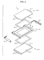
- Fig. 2 shows a perspective view in the state in which the battery unit 11 is disassembled, the upper side of Fig. 2 is a front surface side of the battery unit11, and the downside of Fig. 2 is the back surface side of the battery unit 11.
- the battery cell 121 has electrode terminals 21-1 and 22-1 formed so as to be protruded outward from both side surfaces of a square plate-shaped cell main body 23-1, respectively.
- the electrode terminals 21-1 and 22-1 are provided so as to be extended along one surface (a surface of the front surface side in an example of Fig. 2 ) of the cell main body 23-1.
- the battery cell 121 has a convex shape in which the cell main body 23-1 is protruded from the surface with the electrode terminals 21-1 and 22-1 provided thereon.
- the battery cell 122 has a convex shape in which the electrode terminals 21-2 and 22-2 are provided on the other surface (a surface of the back surface side in the example of Fig. 2 ) of the cell main body 23-2 and the cell main body 23-2 is protruded from the surface with the electrode terminals 21-2 and 22-2 provided thereon.
- the battery cells 12-1 and 12-2 are mounted on the bracket 13 in the state of being combined toward the cell main bodies 23-1 and 23-2 side having the convex shape. That is, the battery cells 12-1 and 12-2 are mounted on the bracket 13 so that the surface with the electrode terminals 21-1 and 22-1 provided thereon faces the front surface side and the surface with the electrode terminals 21-2 and 22-2 faces the back surface side, respectively.
- the bracket 13 has an outer peripheral wall 24 and a rib portion 25.
- the outer peripheral wall 24 is slighter wider than the outer peripheries of the cell main bodies 23-1 and 23-2 of the battery cells 12-1 and 12-2, that is, the outer peripheral wall 24 is formed so as to surround the cell main bodies 23-1 and 23-2 in the state in which the battery cells 12-1 and 12-2 are mounted.
- the rib portion 25 is formed on the inner side of the outer peripheral wall 24 so as to be extended inward from a central portion in the thickness direction of the outer peripheral wall 24.
- the battery cells 12-1 and 12-2 are inserted from the front surface side and the back surface side of the bracket 13 into the outer peripheral wall 24, and bonded to both side surfaces of the rib portion 25 of the bracket 13 by double-sided tapes 16-1 and 16-2 having adhesiveness on both sides.
- the double-sided tapes 16-1 and 16-2 have an approximately ⁇ shape of a predetermined width along the outer peripheral ends of the battery cells 12-1 and 12-2, and the rib portion 25 of the bracket 13 may be provided by an area where the double-sided tapes 16-1 and 16-2 are bonded.
- the rib portion 25 is formed so as to be extended inward from the inside of the outer peripheral wall 24 by a predetermined width along the outer peripheral end of the battery cells 12-1 and 12-2, and the inside of the rib portion 25 is an opening portion.
- the battery cells 12-1 and 12-2 are mounted on the bracket 13 to have a gap of a total dimension of the thickness of the rib portion 25 and the thickness of the double-sided tapes 16-1 and 16-2.
- the gap provided by the gap becomes a space that releases the bulging of the battery cells 12-1 and 12-2.
- the bus bars 14-1 and 14-2 are mounted on both side surfaces of the bracket 13 by the use of the claw and pressure-fit, respectively.
- the electrode terminal 21-1 of the battery cell 121 and the electrode terminal 21-2 of the battery cell 122 are bonded to the bus bar 14-1, and the electrode terminal 22-1 of the battery cell 121 and the electrode terminal 22-2 of the battery cell 122 are bonded to the bus bar 14-2.
- the rib portion 25 of the bracket 13 can be thinned. That is, for example, even when the thickness of the rib portion 25 is equal to or less than 1 mm (about thickness limit of resin molding) of the rib portion 25, the battery cells 12-1 and 12-2 can be bonded on both side surfaces of the rib portion 25, whereby it is possible to obtain suitable rigidity in the battery unit 11 as a whole. Moreover, by thinning the thickness of the rib portion 25, the thickness of the battery unit 11 is thin and the volume is reduced, with the result that the energy density of the battery unit 11 can be improved.
- the battery unit 11 has a structure in which the outer peripheral surfaces (both sides and upper and lower surfaces) of the battery cells 12-1 and 12-2 do not come into contact with the inner peripheral surface of the outer peripheral wall 24 of the bracket 13, and the wide surfaces of the battery cells 12-1 and 12-2 are bonded to the rib portion 25.
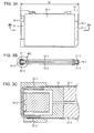
- bus bars 14-1 and 14-2 will be described based on Figs. 3A to 3C .
- Fig. 3A shows a front view of the battery unit
- Fig. 3B shows a cross-sectional view in the direction of an arrow IIIB-IIIB shown in Fig. 3A
- Fig. 3C shows an exploded view of a left end portion in the cross-sectional view of Fig. 3B .
- the battery cells 12-1 and 12-2 are mounted on the bracket 13 in the state of being combined with each other toward the cell main bodies 23-1 and 23-2 sides having a convex shape. For that reason, between the electrode terminal 21-1 of the battery cell 121 and the electrode terminal 21-2 of the battery cell 122, a space corresponding to the thicknesses of the cell main bodies 23-1 and 23-2 is provided. Similarly, a space is also provided between the electrode terminal 22-1 of the battery cell 121 and the electrode terminal 22-2 of the battery cell 122. Thus, the bus bars 14-1 and 14-2 are disposed by the use of the space.
- bus bars 14-1 and 14-2 it is possible to reduce the dimension W of the width direction of the battery unit 11 to promote a reduction in the size of the battery unit 11.
- the electrode terminals 21-1 and 22-1 of the battery cell 12-1 and the electrode terminals 21-1 and 22-2 of the battery cell 122 are disposed on both side surfaces of the battery unit 11, it is possible to integrate the terminal connected to the outside of the battery unit 11 on the upper surface side of the battery unit 11 by the bus bars 14-1 and 14-2.
- Figs. 4A shows a front view of the battery unit 11 and a cross-sectional view in the direction of an arrow IIIIA-IIIIA shown in the front view
- Fig. 4B shows an exploded view of upper and lower end portions in the cross-sectional view of Fig. 4A .
- the cell main bodies 23-1 and 23-2 of the battery cells 12-1 and 12-2 have their battery elements packaged using a laminate film or the like, and there is a necessity to protect them from stress or shock from the outside.
- the bracket 13 has a structure that has a function of holding and protecting the battery cells 12-1 and 12-2 in combination.
- the bracket 13 is formed so that a gap d1 is provided between the outer peripheral sides of the battery cells 12-1 and 12-2 and the inner peripheral side of the outer peripheral wall 24 in the state in which the battery cells 12-1 and 12-2 are mounted on the bracket 13.
- a longitudinal dimension of the outer peripheral wall 24 of the bracket 13 is designed so as to be a dimension of adding the upper gap d1 and the lower gap d1 to the longitudinal dimensions of the cell main bodies 23-1 and 23-2 of the battery cells 12-1 and 12-2.
- a transverse dimension of the outer peripheral wall 24 of the bracket 13 is designed so as to be a dimension of adding the right gap d1 and the left gap d1 to the transverse dimensions of the cell main bodies 23-1 and 23-2 of the battery cells 12-1 and 12-2.
- the bracket 13 has a protective structure that protects the battery cells 12-1 and 12-2 from external shock.
- the bracket 13 is formed so as to be higher than the thicknesses of the battery cells 12-1 and 12-2 by the gap d2.
- the depth from the surface or the back of the outer peripheral wall 24 of the bracket 13 to the rib portion 25 is designed so as to be a dimension (in addition, in the case of using the double-sided tape 16 ( Fig. 2 ), a dimension that considers the thickness of the double-sided tape 16) that adds the gap d2 to the thicknesses of the battery cells 12-1 and 12-2.
- the bracket 13 can also receive the stress in the thickness direction, which can protect the battery cells 12-1 and 12-2 from the stress in the thickness direction.
- Fig. 5A is a perspective view of the battery unit 11
- Figs. 5B and 5C are exploded views of the terminal portion.
- the electrode terminal 21-1 of the battery cell 121 is a terminal of a negative side
- the electrode terminal 22-1 is a terminal of a positive side
- the electrode terminal 21-2 of the battery cell 122 is a terminal of a negative side
- the electrode terminal 22-2 is a terminal of a positive side.
- the electrode terminal 21-1 and the electrode terminal 21-2 are disposed to face each other and are connected to the bus bar 14-1, and the electrode terminal 22-1 and the electrode terminal 22-2 are disposed to face each other and are connected to the bus bar 14-2.
- the capacity of the battery unit 11 becomes twice that of the battery cell single body.
- the electrode terminal 21-1 and the electrode terminal 22-2 are disposed to face each other and are connected to the bus bar 14-1', and the electrode terminal 22-1 and the electrode terminal 22-2 are disposed to face each other and are connected to the bus bar 14-2'.
- the bus bars 14-1 and 14-2 adopt a structure which is divided into two parts by a dotted line shown in Fig. 5C .
- the battery unit 11 by selecting the directions of the battery cells 12-1 and 12-2 upon being mounted on the bracket 13 and adopting a suitable bus bar, the connection between the same poles or between the different poles is possible. Furthermore, by the use of the low cost battery cells 12-1 and 12-2, it is possible to create the battery unit 11 of a serious consideration of capacity or a serious consideration of voltage at low cost.
- Fig. 6A shows a perspective view of the battery unit 11
- Fig. 6B shows a perspective view of the bracket 13 and the bus bars 14-1 and 14-2
- Fig. 6C shows an exploded view of the connection portion.
- the bus bars 14-1 and 14-2 are mounted from both side surfaces of the bracket 13 so that the terminals 31-1 and 31-2 to be electrically connected to the outside of the battery unit 11 are disposed on the upper surface side of the bracket 13. Moreover, in the bus bars 14-1 and 14-2, the side surface portions 32-1 and 32-2 to be disposed on the side surface of the bracket 13 are fixed to the bracket 13.
- a fixing method of fixing the bus bars 14-1 and 14-2 to the bracket 13 a one-touch installation without using a screw is adopted, and for example, the fixing is performed by a fixing method using a pressure-fit and a fixing method using a claw.
- pressure-fit portions 33-1 and 33-2 formed in the lower end portions (the end portion of an opposite side of a side where the terminals 31-1 and 31-2 are provided) of the bus bars 14-1 and 14-2 are used.
- the pressure-fit portions 33-1 and 33-2 have an approximately U-shaped cross section, and the exterior dimensions of both sides are designed to dimensions capable of being pressure-fitted with respect to the dimension of a groove formed on the side of the bracket 13.
- notch portions formed near the upper ends of the side surface portions 32-1 and 32-2 of the bus bars 14-1 and 14-2 are used.
- Fig. 6C the vicinity of the notch portion 34-2 formed in the bus bar 14-2 is shown in an enlarged manner, and a claw portion 41 corresponding to the notch portion 34-2 is formed in the bracket 13.
- the bus bar 14-1 is also fixed by the use of the claw portion 41 and the notch portion 34-2.
- the bus bars 14-1 and 14-2 are fixed to the bracket 13, whereby, a design having a screw length necessary in terms of strength is not necessary but the battery unit 11 can be reduced in size, for example, compared to the case of adopting the fixing method using the screw. Furthermore, by adopting the fixing method using the pressure-fit and the claw, it is possible to fix the bus bars 14-1 and 14-2 to the bracket 13 with minimum effort.
- plating is performed so as to have corrosion resistance.
- the components are suspended by a wire, and it is necessary that suspension holes for suspending by a wire are also provided in the bus bars 14-1 and 14-2.
- suspension holes for suspending by a wire are also provided in the bus bars 14-1 and 14-2.
- suspension holes through holes provided in the bus bars 14-1 and 14-2 will be described with reference to Figs. 7A to 7C .
- Fig. 7A shows a front view of the battery unit 11
- Fig. 7B shows a perspective view of the state in which the bracket 13, and the bus bars 14-1 and 14-2 are combined with each other
- Fig. 7C shows a perspective view of the bus bar 14.
- a range shown in the bus bar 14-2 by an arrow that is, a range from a position depending on the lower end of the electrode terminal 22-1 of the battery cell 121 to a tip of the terminal 31-2 is a range through which the electric current passes.
- a suspension hole 35 is formed outside the range through which the electric current passes. That is, as shown in Fig. 7C , in a pressure-fit portion 33 provided in the lower end of the bus bar 14, a suspension hole 35 is formed. In this manner, by providing the suspension hole 35 outside the range through which the electric current passes, it is possible to avoid a reduction in cross-sectional area of the range through which the electric current passes.
- the bus bar 14 plays the role of collecting and transmitting the electric current from the battery cells 12-1 and 12-2, but, in order to cause a large electric current to flow, a certain degree of cross-sectional area is necessary. Since it is difficult to make the width of the terminal 31 wider than the width of the battery unit 11, in some cases, it is difficult to achieve a sufficient width due to a geometric constraint. Thus, in the bus bar 14, the cross-section area is secured without widening the width by folding back (heming bend) the material.
- bus bar 14 The shape of the bus bar 14 will be described based on Figs, 8A to 8C .
- Fig. 8A shows a perspective view of the bus bar 14, and Figs. 8B and 8C show enlarged views of the vicinity of the terminal 31.
- the side surface portion 32 connected to the electrode terminals 21 or 22 of the battery cell 12 has a shape in which the metal plate material is bent in the form of an approximate U shape.
- the terminal 31 it is necessary that the terminal 31 is thin to fit the width of the battery unit 11, the terminal 31 has a structure in which the metal plate material is folded back in this portion.
- a notch necessary after the working is formed in the base thereof, and notches 36 and 37 are formed in the bus bar 14.
- the formed positions of the notches 36 and 37 are shifted. For example, if the notches 36 and 37 are formed from the opposite sides of the same position, respectively, the cross-section in partially becomes thin in that position.
- the battery unit 11 is configured as mentioned above, and a plurality of battery units 11 is combined with each other so that a predetermined voltage can be obtained.
- the battery module 51 includes a module case 52, a rubber sheet portion 53, a battery portion 54, a battery cover 55, a fixing sheet portion 56, an electric part portion 57, and a module cover 58.
- the module case 52 is a case for storing the battery unit 11 and mounting the same on the equipment used, and in the configuration example of Fig. 9 , the module case 52 has a dimension capable of storing 24 battery units 11.
- the rubber sheet portion 53 is a sheet that is laid on the bottom surface of the battery unit 11 to mitigate shock or the like.
- a sheet of rubber sheet is provided for each three battery units 11, and eight rubber sheets are provided so as to cope with 24 battery units 11.
- the battery portion 54 is configured so that 24 battery units 11 are combined with each other. Furthermore, the battery portion 54 has a connection configuration in which three battery units 11 are connected to each other in parallel to configure a parallel block 61, and eight parallel blocks 61 are connected to each other in series.
- the battery cover 55 is a cover for fixing the battery portion 54, and is provided with an opening corresponding to the terminal 31 of the bus bar 14 of the battery unit 11.
- the fixing sheet portion 56 is a sheet which is disposed on the upper surface of the battery cover 55, comes into close contact with the battery cover 55 and the module cover 58 and is fixed thereto when the module cover 58 is fixed to the module case 52.
- the electric part portion 57 has electric components such as a metal plate material that connects the terminal 31 of the bus bar 14 of the battery unit 11 or a charging or discharging control circuit that controls the charging or the discharging of the battery unit 11.
- the charging or discharging circuit is disposed in a space, for example, between the bus bars 14 forming two rows in the battery portion 54.
- the module cover 58 is a cover for closing the module case 52 after each portion is stored in the module case 52.
- a parallel block 61 in which three battery units 11 are connected to each other, is connected to the battery module 51 in series, whereby the battery portion 54 is configured, and the series connection is performed by the metal plate material included in the electric part portion 57.
- the parallel blocks 61 are disposed, respectively, so that the direction of the terminal is alternated for each parallel block 61, that is, a positive terminal and a negative terminal are aligned by the parallel blocks 61 adjacent to each other.
- the parallel blocks 61 there is a necessity for a scheme of avoiding the terminals of the same poles being aligned by the parallel blocks 61 adjacent to each other.
- a parallel block 61-1 constituted by the battery units 11-1 to 11-3 and a parallel block 61-2 constituted by the battery units 11-4 to 11-6 are stored within the module case 52 by an arrangement in which the positive terminal is adjacent to the negative terminal.
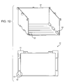
- a chamfered portion 15 formed in one corner portion of the downside of the bracket 13 of the battery unit 11 is used.
- the battery units 11-1 to 11-3 are combined to each other so that the respective chamfered portions 15-1 to 15-3 are in the same direction, thereby forming the chamfered region 62.
- slope portions 63 depending on the slope of the chamfered region 62 are formed, and the slope portions 63 are alternately disposed by a length depending on the thickness of three battery units 11.
- Fig. 13 shows a perspective view in which the battery unit 11 is viewed from the front surface side and the rear surface side, and an enlarged view of the upper corner portion of the battery unit 11.
- a concave portion 71 is formed in the left corner portion, and a concave portion 72 is formed in the right corner portion. Furthermore, in the upper side of the rear surface side of the bracket 13, a convex portion 73 is formed in the left corner portion, and a convex portion 74 is formed in the right corner portion.
- the convex portion 73 and the convex portion 74 of the other battery unit 11 are inserted into the concave portion 71 and the concave portion 72 of one battery unit 11. Furthermore, a transverse deviation of the concave portion 71 after overlapping by the longitudinal rib is prevented.
- the convex portions 73-2 and 74-2 of the battery unit 11-2 are inserted into the concave portions 71-1 and 72-1 (although they are not shown, they are formed on the back side of the convex portions 73-1 and 74-1) of the battery unit 11-1.
- the convex portions 73-3 and 74-3 of the battery unit 11-3 are inserted into the concave portions 71-2 and 72-2 (although they are not shown, they are formed on the back side of the convex portions 73-2 and 74-2) of the battery unit 11-2.
- the concave portions 71-3 and 72-3 of the battery unit 11-3 face the concave portions 71-2 and 72-2 (although they are not shown, they are formed on the back side of the convex portions 73-2 and 74-2) of the battery unit 11-2.
- the battery unit 11-3 transversely slides with respect to the battery unit 11-2.
- the battery blocks are not assembled as the parallel block 61, and the terminals being connected in the state of the wrong direction is avoided.
- Fig. 15 shows an example of the case where the parallel block 61 is inserted into the module case 52 in a correct direction.
- Fig. 16 shows an example of the case where the parallel block 61 is inserted into the module case 52 in the wrong direction.
- the concave portions 71 and 72 and the convex portions 73 and 74 formed in the bracket 13 are configured so as to have both of a function of avoiding the battery cells 12 being combined with each other in the different direction upon stacking the battery cells 12 in the plane direction, and a function of avoiding the parallel block 61 being inserted in the different direction when storing the parallel block 61 in the module case 52 from the upper direction.
- the battery unit 11 in addition to the insertion prevention in the wrong direction using the chamfered region 62 as described with reference to Figs. 11A, 11B , and 12 , the insertion in the wrong direction is prevented by the use of the convex portions 73 and 74 formed in the bracket 13. In this manner, by taking a plurality of prevention measures, the terminals of the parallel blocks 61 being erroneously connected to each other is prevented, whereby the battery unit 11 can be further safely used.
- Fig. 17 is a perspective view that shows a modified example of a battery unit of a first embodiment.
- a battery unit 11' shown in Fig. 17 has two battery cells 12-1 and 12-2 similar to the battery unit 11 of Fig. 1 .
- an output terminal 81-1 is electrically connected to the upper surface of the terminal 31-1 of the bus bar 14-1
- an output terminal 81-2 is electrically connected to the upper surface of the terminal 31-2 of the bus bar 14-2.
- the output terminals 81-1 and 81-2 are used in connecting the battery unit 11' with an external device by an electric cable or the like and outputs the electric power accumulated in the battery unit 11' to the external device.
- the output terminals 81-1 and 81-2 are rod-like members formed with screw grooves, and can fix an electric cable with an O type crimping terminal mounted thereon by the use of a nut.
- wall portions 82-1 and 82-2 are formed near both ends of the upper surface of the bracket 13'.
- the wall portion 82-1 has an approximate U shape that is opened in a right side surface direction of the bracket 13' when viewed from the upside, and is formed so as to surround the terminal 31-1 of the bus bar 14-1 from three sides in the state in which the bus bar 14-1 is mounted on the bracket 13'.
- the wall portion 82-2 is also formed so as to surround the terminal 31-2 of the bus bar 14-2 from three sides.
- a cooling case 92-1 is mounted on the front surface side of the battery unit 11' via a heat conduction sheet 91-1
- a cooling case 92-2 is mounted on the rear surface side of the battery unit 11' via a heat conduction sheet 91-2.
- the cooling cases 92-1 and 92-2 are formed, for example, by bending an end portion of a thin metal plate such as aluminum. Moreover, the cooling cases 91-1 and 92-2 have shapes that cover the front surface and the rear surface of the battery unit 11' and cover the bottom surface of the battery unit 11' in the state in which the cooling cases 92-1 and 92-2 are combined with each other.
- the cooling case 92-1 and the battery cell 121 come into close contact with each other by the heat conduction sheet 91-1.
- the cooling case 92-2 and the battery cell 122 come into close contact with each other by the heat conduction sheet 91-2.
- the heat garneted in the battery cells 12-1 and 12-2 is effectively transferred and radiated to the cooling cases 92-1 and 92-2 via the heat conduction sheets 91-1 and 91-2.
- the cooling cases 92-1 and 92-1 are mounted to the battery unit 11', it is necessary that a portion between the cooling cases 92-1 and 92-2 and the bus bar 14-1 (including the electrode terminals 21-1 and 22-2 to be welded to the bus bar 14-1) is insulated and a portion between the cooling cases 92-1 and 92-2 and the bus bar 14-2 (including the electrode terminals 21-1 and 22-2 to be welded to the bus bar 14-2) is insulated. For that reason, the insulation sheets 93-1 and 93-2 having ductility are used.
- the insulation sheets 93-1 are bent in an approximate U shape so as to follow the right side surface portion of the battery unit 11' to cover the bus bar 14-1 and are interposed between the bus bar 14-1 and the cooling cases 92-1 and 92-2.
- the insulation sheets 93-2 are bent in an approximate U shape so as to follow the left side surface portion of the battery unit 11' to cover the bus bar 14-2 and are interposed between the bus bar 14-2 and the cooling cases 92-1 and 92-2.
- side covers 94-1 and 94-2 are mounted on both side surfaces of the battery unit 11'.
- the side cover 94-1 has an approximately L shape that covers a part (for example, the terminal 31-1 of the bus bar 14-1 other than the output terminal 81-1) of the right side front surface of the battery unit 11' and the upper surface of the battery unit 11'. Furthermore, the side cover 94-2 also has an approximately L shape. Furthermore, the side covers 94-1 and 94-2 are formed with claw portions for fixing the cooling cases 92-1 and 92-2 as described later with reference to Figs. 20A and 20B .
- the cooling cases 92-1 and 92-2 are members having the same shape. Moreover, the cooling cases 92-1 and 92-2 are formed in the shape that covers the bottom front surface of the battery unit 11' in the state in which the cooling cases 92-1 and 92-2 are combined with each other without covering the bottom front surface of the battery unit 11'.
- Figs. 19A and 19B show the battery unit 11' of the state in which the cooling cases 92-1 and 92-2 are mounted.
- Fig. 19A shows the battery unit 11' of the single body
- Fig. 19B shows the state in which four battery units 11'-1 to 11'-4 are arranged.
- the battery unit 11' is in the state in which the front surface side, the rear surface side, and the bottom surface side thereof are covered with the cooling cases 92-1 and 92-2.
- the cooling cases 92-1 and 92-2 cover the bottom surface side of the battery unit 11', whereby the heat generated in the battery cells 12-1 and 12-2 is easily radiated from the bottom surface side of the battery unit 11' via the cooling cases 92-1 and 92-2.
- the thin plate of a material having high thermal conductivity as the cooling cases 92-1 and 92-2, it is possible to suppress that the volume of the battery unit 11' is increased.
- the cooling efficiency can be improved.
- Fig. 20A shows a left side portion of the battery unit 11' in the state in which the cooling cases 92-1 and 92-2 interposes the battery unit 11' therebetween and before the side cover 94-2 is mounted thereon. Furthermore, Fig. 20B shows an enlarged view of an upper portion of the battery unit 11' shown in Fig. 20A .
- claws portions are formed in three places of both side ends thereof, respectively, and the claw portions are bent so as to be disposed on the side surface of the battery unit 11' in the state of being mounted on the battery unit 11'.
- engagement holes are formed, respectively.
- claw portions are formed in the places corresponding to the engagement holes formed in the claw portions of the cooling cases 92-1 and 92-2, respectively.
- the engagement holes of the cooling cases 92-1 and 92-2 are formed on the tip end side of a white arrow shown in Fig. 20A , and the claw portion of the side cover 94-2 is formed on the proximal end side of the white arrow.
- a claw portion 97 formed in the side cover 94-2 is inserted is inserted into an engagement hole 96 of a claw portion 95 formed in the cooling case 92-1, and the claw portion 97 and the engagement hole 96 are engaged with each other.
- another claw portion of the side cover 94-2 is engaged with another engagement hole of the cooling cases 92-1 and 92-2.
- the claw portion of the side cover 94-1 is engaged with the engagement holes of the cooling cases 92-1 and 92-2.
- the side covers 94-1 and 94-2 can reliably fix the cooling cases 92-1 and 92-2 to the battery unit 11'.
- the cooling cases 92-1 and 92-2 are mounted so as to interpose the battery unit 11' therebetween, for example, it is possible to cope with the expansion of the battery cell 12. That is, it is possible to adopt a configuration in which the side covers 94-1 and 94-2 are slightly moved so as to be opened in the width direction according to the expansion of the battery cell 12.
- the battery unit 11 has a structure in which the bracket 13 protects the battery cells 12-1 and 12-2.
- the battery unit 11' has a structure in which the battery cells 12-1 and 12-2 are protected, and the bracket 13' and the side covers 94-1 and 94-2 protect the end surfaces of the cooling cases 92-1 and 92-2.
- Fig. 21A shows a front view of the battery unit 11'
- Fig. 21B shows an enlarged view of an upper end portion in the cross-sectional view in the direction of the arrow XXIB-XXIB shown in Fig. 21A .
- the bracket 13' is formed so that the battery cells 12-1 and 12-2 are mounted and the outer peripheral wall 24 of the upper surface side is raised on both sides by a gap d3 further than the dimension D in the thickness direction in the state in which the cooling cases 92-1 and 92-2 are mounted.
- the depth from the surface of the outer peripheral wall 24 of the upper surface side of the bracket 13' to the rib portion 25 is designed so as to become a dimension (furthermore, in the case of using the double-sided tape 16 ( Fig. 2 ), a dimension considering the thickness of the double-sided tape 16) in which the gap d3 is added to the thickness dimensions of the battery cell 121 and the cooling case 92-1.
- the depth from the back surface of the outer peripheral wall 24 of the upper surface side of the bracket 13' to the rib portion 25 is also designed so as to be a dimension in which the gap d3 is added to the thickness dimensions of the battery cell 122 and the cooling case 92-2.
- the thickness direction (thickness direction when viewed as a whole of the battery unit 11') of the side covers 94-1 and 94-2 is also designed so as to be a dimension in which the gap d3 is added to both side surfaces of the dimension D mentioned above like the outer peripheral wall 24 of the upper surface side of the bracket 13'.
- the bracket 13' by designing the dimension of the outer peripheral wall 24 of the upper surface side of the bracket 13' and the dimensions the side covers 94-1 and 94-2, the upper end surfaces and the left and right end surfaces of the cooling cases 92-1 and 92-2 can be covered with the bracket 13' and the side covers 94-1 and 94-2. As a result, it is possible to protect the end surfaces of the cooling cases 92-1 and 92-2 from stress or shock from the outside.
- the whole outer peripheral surfaces of the battery cells 12-1 and 12-2 can be surrounded by the bracket 13' and the cooling cases 92-1 and 92-2, the battery cells 12-1 and 12-2 can be reliably protected from the outside.
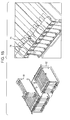
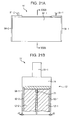
- Fig. 22 is an exploded view that shows a configuration example of a second embodiment to which an embodiment of the present disclosure is applied.
- a battery unit 101 is common to the battery unit 11 of Fig. 2 in that the battery cells 12-1 and 12-2, bus bars 14-1 and 14-2, and the double-sided tapes 16-1 and 16-2 are included. Meanwhile, the battery unit 101 is different from the battery unit 11 in that a bracket 102 having a configuration different form that of the bracket 13 is included.
- the bracket 102 of the battery unit 11 is integrally configured, meanwhile the bracket 102 of the battery unit 101 is configured so that the bracket parts 103 and 104 and the aluminum corrugation 105 are combined with each other.
- the bracket parts 103 and 104 are formed in a shape in which the rib portion 25 is excluded from the bracket 13 and the bracket 13 is divided into two parts in the center in the thickness direction. By combining the bracket parts 103 and 104, the bracket parts have approximately the same shape as that of the outer peripheral wall 24 of the bracket 13.
- the aluminum corrugation 105 is a member that is formed of a thin plate of aluminum, has the same thickness as that of the rib portion 25 of the bracket 13, and a channel is provided inside thereof through which a refrigerant (for example, air, water or the like) is circulated. That is, as shown in Fig. 23 , the aluminum corrugation 105 is configured so that an aluminum wave plate 11-3 is interposed between two aluminum flat plates 111 and 112.
- a refrigerant for example, air, water or the like
- bracket parts 103 and 104 are combined with each other with the aluminum corrugation 105 configured in this manner interposed therebtween, whereby the bracket 102 having a path, through which the refrigerant is circulated between the battery cells 12-1 and 12-2, is configured.
- a double-sided tape is used which adopts a material (a heat conduction sheet) of high thermal conductivity as the double-sided tapes 16-1 and 16-2.
- the double-sided tapes 16-1 and 16-2 can have a shape in which the whole surfaces of the battery cells 12-1 and 12-2 are attached to the aluminum corrugation 105.
- the bracket 102 is configured so that a channel of the aluminum corrugation 105 penetrates through the bottom surface and the upper surface of the battery unit 101.
- a channel of the aluminum corrugation 105 penetrates through the bottom surface and the upper surface of the battery unit 101.
- the thickness of the aluminum corrugation 105 is set to about the same thickness (for example, about 0.8 mm) as that of the rib portion 25 of the bracket 13, it is possible to configure the battery unit 101 without increasing the volume from the battery unit 11. That is, it is possible to realize the battery unit 101 having the improved cooling performance while reducing the whole volume.
- the aluminum corrugation 105 is not limited to the configuration as shown in Fig. 23 .
- the bracket 102 may be integrally formed by performing an insert molding of the aluminum corrugation 105 other than the configuration in which the aluminum corrugation 105 is interposed between the bracket parts 103 and 104.
- Fig. 25 shows the state in which the rubber sheet portion 53, the battery portion 54, and the electric part portion 57 are combined with each other in the configuration of the battery module 51 described based on Fig. 9 .
- the parallel block 61 ( Fig. 10 ) with three battery units 11 connected in parallel is connected in series to configure the battery portion 54, and the terminals 31 of six battery units 11 are electrically connected.
- a method of electrically connecting the plurality of terminals 31 for example, there is a method of interposing the plurality of terminals 31 by the metal plate material in the vertical direction and fixing the metal plate material by the use of a screw.
- a method is adopted which electrically connects the plurality of terminals 31 by the use of a connector 121 having a structure that is capable of being mounted on the plurality of terminals 31 by one touch.
- Fig. 26A shows an enlarged view of an elliptical portion shown in Fig. 25
- Fig. 26B shows a perspective view of the connector 121.
- Fig. 26A shows a portion in which six battery units 11A to 11F are connected by the connector 121, and a connection configuration is provided in which the terminals 31A to 31C of the positive side of the battery units 11A to 11C are connected in parallel, the terminals 31D to 31F of the negative side of the battery units 11D to 11F are connected in parallel, the terminals 31A to 31C of the positive side of the battery units 11A to 11C and the terminals 31D to 31F of the negative side of the battery units 11D to 11F are connected in series.
- the insertion portions 123A to 123F are formed in the places corresponding to the terminals 31A to 31F, and the terminals 31A to 31F are inserted into the insertion portions 123A to 123F, whereby the terminals 31A to 31F are electrically connected to each other in the inner portion of the connector 121.
- a stopper bar 122 for locking the connector 121 is provided. Both ends of the stopper bar 122 are able to be fixed to the battery units 11A and 11F, whereby a worker pushes the connector 121 in a direction in which the terminals 31A to 31F are inserted into the insertion portions 123A to 123F of the connector 121, and then locks the rear surface (a surface of an opposite side of the surface formed with the insertion portions 123A to 123F) of the connector 121 by the stopper bar 122, thereby mounting the connector 121.
- the connector 121 is configured by assembling the metallic connector 131 and the resin case 132.
- Fig. 27A shows a perspective view in which the connector 121 is viewed from the upper surface side
- Fig. 27B shows a perspective view in which the connector 121 is viewed from the bottom surface side.
- a groove portion 133 depending on the thickness of the terminal 31 is formed, and a plurality of contact portions (not shown) is provided on the upper and lower surfaces of the groove portion 133.
- the plurality of contact portions of the metallic connector 131 is disposed so as to be able to come into contact with one terminal 31 at a plurality of points, and the metallic connector 131 is electrically connected to the terminal 31 by so-called multipoint contact.
- the resin case 132 is a case that houses the metallic connector 131 so as to cover a portion other than the bottom surface of the metallic connector 131, and the insertion portions 123A to 123F are formed at the height corresponding to the groove portion 133 of the metallic connector 131. Furthermore, claw portions 134-1 to 134-4 for holding the stored metallic connector 131 are formed in the vicinity of the bottom surface of the inner peripheral surface of the resin case 132.
- the notch portions are formed for each of insertion portions 123A to 123F, whereby the connector 121 can be further strongly mounted on the bracket 13 by the use of the notch portions.
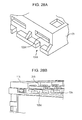
- Fig. 28A shows the vicinity of the insertion portion 123A of the connector 121 and Fig. 28B shows the vicinity of the terminal 31A.
- the cutout portion 124A is formed on the lower side of the insertion portion 123A. Furthermore, as shown in Fig. 28B , a T-shaped rib 125A is formed on the lower portion of the terminal 31A of the upper surface of the bracket 13A.
- the terminal 31A is inserted into the insertion portion 123A and the T-shaped rib 125A is inserted into the cutout portion 124A.
- the T-shaped rib 125A is inserted into the cutout portion 124A, whereby the connector 121 is fixed in a direction perpendicular to the shown arrow, and then the connector 121 is fixed in the direction of the shown arrow by the stopper bar 122.
- the connector 121 is reliably fixed to the brackets 13A to 13F, whereby the connector 121 can include further high vibration resistance.
Landscapes
- Chemical & Material Sciences (AREA)
- Chemical Kinetics & Catalysis (AREA)
- Electrochemistry (AREA)
- General Chemical & Material Sciences (AREA)
- Inorganic Chemistry (AREA)
- Engineering & Computer Science (AREA)
- Manufacturing & Machinery (AREA)
- Battery Mounting, Suspending (AREA)
- Connection Of Batteries Or Terminals (AREA)
- Secondary Cells (AREA)
Applications Claiming Priority (2)
| Application Number | Priority Date | Filing Date | Title |
|---|---|---|---|
| JP2010201918 | 2010-09-09 | ||
| JP2010227749A JP5553163B2 (ja) | 2010-09-09 | 2010-10-07 | バッテリユニット |
Publications (1)
| Publication Number | Publication Date |
|---|---|
| EP2434561A1 true EP2434561A1 (en) | 2012-03-28 |
Family
ID=44653953
Family Applications (1)
| Application Number | Title | Priority Date | Filing Date |
|---|---|---|---|
| EP11006822A Withdrawn EP2434561A1 (en) | 2010-09-09 | 2011-08-19 | Battery unit |
Country Status (5)
| Country | Link |
|---|---|
| US (2) | US9419256B2 (zh) |
| EP (1) | EP2434561A1 (zh) |
| JP (1) | JP5553163B2 (zh) |
| KR (1) | KR101932283B1 (zh) |
| CN (2) | CN102403481B (zh) |
Cited By (5)
| Publication number | Priority date | Publication date | Assignee | Title |
|---|---|---|---|---|
| EP2849275A4 (en) * | 2012-05-08 | 2015-05-27 | Lg Chemical Ltd | BATTERY MODULE WITH A HIGHLY EFFICIENT COOLING STRUCTURE |
| EP3333933A4 (en) * | 2015-08-07 | 2019-01-02 | IHI Corporation | Cell module |
| CN111477800A (zh) * | 2020-04-30 | 2020-07-31 | 昆山宝创新能源科技有限公司 | 电池模块、电池包和车辆 |
| CN111477829A (zh) * | 2020-04-30 | 2020-07-31 | 昆山宝创新能源科技有限公司 | 电池模组和汽车 |
| CN111477828A (zh) * | 2020-04-30 | 2020-07-31 | 昆山宝创新能源科技有限公司 | 电池模块及具有其的电池模组和汽车 |
Families Citing this family (29)
| Publication number | Priority date | Publication date | Assignee | Title |
|---|---|---|---|---|
| US20140162114A1 (en) * | 2011-07-15 | 2014-06-12 | Nec Energy Devices, Ltd. | Battery module |
| JP2013214497A (ja) * | 2012-03-08 | 2013-10-17 | Nissan Motor Co Ltd | 組電池 |
| KR20140085890A (ko) * | 2012-12-28 | 2014-07-08 | 현대자동차주식회사 | 고전압 배터리팩용 배터리모듈 조립체 |
| JP6122150B2 (ja) * | 2013-05-15 | 2017-04-26 | エルジー・ケム・リミテッド | 新規な構造の電池モジュールアセンブリー |
| EP2991131B1 (en) | 2013-05-15 | 2017-12-20 | Lg Chem, Ltd. | Battery module assembly |
| KR101709555B1 (ko) * | 2013-07-31 | 2017-02-23 | 주식회사 엘지화학 | 냉매 유로를 포함하는 전지모듈 어셈블리 |
| CN105453302B (zh) | 2013-08-09 | 2018-10-02 | 日立汽车系统株式会社 | 蓄电模块 |
| DE102013109808A1 (de) * | 2013-09-09 | 2015-03-12 | Dr. Ing. H.C. F. Porsche Aktiengesellschaft | Batterieanordnung |
| US9123949B2 (en) * | 2013-09-17 | 2015-09-01 | Lg Chem, Ltd. | Battery module and battery cell |
| US9123950B2 (en) * | 2013-09-26 | 2015-09-01 | Lg Chem, Ltd. | Battery module and battery cell |
| WO2016072594A1 (ko) * | 2014-11-05 | 2016-05-12 | 주식회사 엘지화학 | 이중 측벽 구조를 가지는 카트리지 프레임 및 이를 포함하는 배터리 모듈 |
| KR101823584B1 (ko) * | 2015-03-04 | 2018-01-30 | 주식회사 엘지화학 | 전지 팩 |
| JP2016177934A (ja) * | 2015-03-19 | 2016-10-06 | 株式会社オートネットワーク技術研究所 | 蓄電パック |
| KR102408824B1 (ko) * | 2015-06-22 | 2022-06-13 | 삼성에스디아이 주식회사 | 이차 전지 및 이차 전지 모듈 |
| EP3363060B1 (en) | 2015-10-16 | 2021-03-10 | Robert Bosch GmbH | Terminal arrangement for an energy storage device |
| KR200491844Y1 (ko) * | 2015-11-12 | 2020-06-16 | 한국단자공업 주식회사 | 배터리모듈용 직렬연결장치 |
| JP6719330B2 (ja) * | 2016-08-22 | 2020-07-08 | Fdk株式会社 | 電池ユニット |
| CN109792096B (zh) * | 2016-10-24 | 2023-06-02 | 株式会社村田制作所 | 电池组 |
| JP6802977B2 (ja) * | 2017-02-27 | 2020-12-23 | 株式会社オートネットワーク技術研究所 | 蓄電ユニット |
| US10317967B2 (en) * | 2017-03-03 | 2019-06-11 | Klas Technologies Limited | Power bracket system |
| CN107240504A (zh) * | 2017-07-21 | 2017-10-10 | 中车青岛四方车辆研究所有限公司 | 硬壳化软包电容模组及系统 |
| KR102270828B1 (ko) | 2017-12-19 | 2021-06-29 | 주식회사 엘지에너지솔루션 | 버스바 어셈블리를 구비한 배터리 모듈 |
| CN108258180B (zh) * | 2018-01-16 | 2020-09-29 | 宁德时代新能源科技股份有限公司 | 集流构件和电池 |
| JP2019175716A (ja) * | 2018-03-29 | 2019-10-10 | 株式会社東芝 | 組電池 |
| CN108565367B (zh) * | 2018-04-02 | 2020-11-10 | 广州明美新能源股份有限公司 | 一种基于弹性支架保护的单电芯电池 |
| US11063320B2 (en) * | 2019-01-08 | 2021-07-13 | Lg Chem, Ltd. | Terminal busbar |
| JP7335100B2 (ja) * | 2019-06-21 | 2023-08-29 | 本田技研工業株式会社 | 蓄電モジュール |
| JP7544497B2 (ja) | 2020-03-19 | 2024-09-03 | 株式会社Aescジャパン | 組電池 |
| CN112582756A (zh) * | 2020-12-11 | 2021-03-30 | 孚能科技(赣州)股份有限公司 | 一种电池模块成组结构以及电池模组 |
Citations (10)
| Publication number | Priority date | Publication date | Assignee | Title |
|---|---|---|---|---|
| JPH11176400A (ja) * | 1997-10-06 | 1999-07-02 | Japan Storage Battery Co Ltd | 電池ケース |
| US20040050414A1 (en) * | 2002-07-30 | 2004-03-18 | Nissan Motor Co., Ltd. | Module battery |
| US20050026014A1 (en) * | 2003-07-31 | 2005-02-03 | Michael Fogaing | Polymer batteries having thermal exchange apparatus |
| US20050042511A1 (en) * | 2002-06-03 | 2005-02-24 | Hiroshi Kaneta | Module |
| WO2007091757A1 (en) * | 2006-02-09 | 2007-08-16 | Lg Chem, Ltd. | Frame member for fabrication of battery module |
| DE102008016936A1 (de) * | 2007-04-05 | 2008-10-09 | Behr Gmbh & Co. Kg | Elektrochemische Energiespeichereinheit |
| JP2009105058A (ja) | 2004-02-03 | 2009-05-14 | Shin Kobe Electric Mach Co Ltd | 組電池 |
| US20090208828A1 (en) * | 2005-06-17 | 2009-08-20 | Nec Corporation | Electric device assembly and film-covered electric device structure |
| JP2010201918A (ja) | 2009-02-09 | 2010-09-16 | Mitsubishi Paper Mills Ltd | 感熱プリンタの出力方法 |
| JP2010227749A (ja) | 2009-03-26 | 2010-10-14 | Jfe Engineering Corp | 排ガス処理方法 |
Family Cites Families (20)
| Publication number | Priority date | Publication date | Assignee | Title |
|---|---|---|---|---|
| JP4483162B2 (ja) * | 2002-08-22 | 2010-06-16 | 日産自動車株式会社 | 積層型電池、組電池、電池モジュール並びに電気自動車 |
| JP3972884B2 (ja) * | 2003-10-10 | 2007-09-05 | 日産自動車株式会社 | 組電池 |
| JP4483489B2 (ja) * | 2004-09-02 | 2010-06-16 | 日産自動車株式会社 | 組電池 |
| JP4457931B2 (ja) * | 2005-03-17 | 2010-04-28 | トヨタ自動車株式会社 | 電池モジュール |
| CN101558151B (zh) | 2006-03-23 | 2015-10-21 | 普拉里斯坦有限公司 | 细胞扩增方法和藉此产生的细胞和条件培养基用于治疗的用途 |
| KR100889241B1 (ko) * | 2006-10-23 | 2009-03-17 | 주식회사 엘지화학 | 전지모듈의 전극단자 접속부재 |
| JP2008166191A (ja) * | 2006-12-28 | 2008-07-17 | Sanyo Electric Co Ltd | 電池パック |
| JP5236210B2 (ja) * | 2007-05-10 | 2013-07-17 | カルソニックカンセイ株式会社 | バッテリの電池モジュール構造 |
| JP4508221B2 (ja) * | 2007-08-27 | 2010-07-21 | 豊田合成株式会社 | 組電池装置 |
| KR101054833B1 (ko) * | 2007-10-29 | 2011-08-05 | 에스케이이노베이션 주식회사 | 리튬 2차 전지 단위 셋 및 리튬 2차 전지 셋 |
| DE102007052330A1 (de) * | 2007-10-31 | 2009-05-07 | Johnson Controls Hybrid And Recycling Gmbh | Rundzellenakkumulator |
| US20090197160A1 (en) * | 2008-01-31 | 2009-08-06 | Sanyo Electric Co., Ltd. | Stack type battery |
| JP4632097B2 (ja) * | 2008-03-05 | 2011-02-16 | 株式会社デンソー | 組電池 |
| JP4539742B2 (ja) * | 2008-03-18 | 2010-09-08 | Tdk株式会社 | 電気化学デバイス |
| US8035986B2 (en) * | 2008-06-30 | 2011-10-11 | Lg Chem, Ltd. | Battery cell interconnect and voltage sensing assembly and method for coupling battery cell assemblies thereto |
| JP5305780B2 (ja) * | 2008-08-19 | 2013-10-02 | 三洋電機株式会社 | 車両用の組電池 |
| WO2010114311A2 (ko) * | 2009-04-01 | 2010-10-07 | 주식회사 엘지화학 | 안전성이 향상된 전지모듈 |
| US9337456B2 (en) * | 2009-04-20 | 2016-05-10 | Lg Chem, Ltd. | Frame member, frame assembly and battery cell assembly made therefrom and methods of making the same |
| KR101259757B1 (ko) * | 2009-12-04 | 2013-05-07 | 주식회사 엘지화학 | 우수한 냉각 효율성과 콤팩트한 구조의 전지모듈 및 중대형 전지팩 |
| US8673473B2 (en) * | 2010-08-10 | 2014-03-18 | GM Global Technology Operations LLC | Integrated cooling fin and frame |
-
2010
- 2010-10-07 JP JP2010227749A patent/JP5553163B2/ja active Active
-
2011
- 2011-08-19 EP EP11006822A patent/EP2434561A1/en not_active Withdrawn
- 2011-08-31 US US13/222,211 patent/US9419256B2/en active Active
- 2011-09-01 CN CN201110257061.2A patent/CN102403481B/zh active Active
- 2011-09-01 CN CN201610258022.7A patent/CN105789496B/zh active Active
- 2011-09-01 KR KR1020110088659A patent/KR101932283B1/ko active IP Right Grant
-
2016
- 2016-08-12 US US15/235,873 patent/US10164222B2/en active Active
Patent Citations (10)
| Publication number | Priority date | Publication date | Assignee | Title |
|---|---|---|---|---|
| JPH11176400A (ja) * | 1997-10-06 | 1999-07-02 | Japan Storage Battery Co Ltd | 電池ケース |
| US20050042511A1 (en) * | 2002-06-03 | 2005-02-24 | Hiroshi Kaneta | Module |
| US20040050414A1 (en) * | 2002-07-30 | 2004-03-18 | Nissan Motor Co., Ltd. | Module battery |
| US20050026014A1 (en) * | 2003-07-31 | 2005-02-03 | Michael Fogaing | Polymer batteries having thermal exchange apparatus |
| JP2009105058A (ja) | 2004-02-03 | 2009-05-14 | Shin Kobe Electric Mach Co Ltd | 組電池 |
| US20090208828A1 (en) * | 2005-06-17 | 2009-08-20 | Nec Corporation | Electric device assembly and film-covered electric device structure |
| WO2007091757A1 (en) * | 2006-02-09 | 2007-08-16 | Lg Chem, Ltd. | Frame member for fabrication of battery module |
| DE102008016936A1 (de) * | 2007-04-05 | 2008-10-09 | Behr Gmbh & Co. Kg | Elektrochemische Energiespeichereinheit |
| JP2010201918A (ja) | 2009-02-09 | 2010-09-16 | Mitsubishi Paper Mills Ltd | 感熱プリンタの出力方法 |
| JP2010227749A (ja) | 2009-03-26 | 2010-10-14 | Jfe Engineering Corp | 排ガス処理方法 |
Cited By (5)
| Publication number | Priority date | Publication date | Assignee | Title |
|---|---|---|---|---|
| EP2849275A4 (en) * | 2012-05-08 | 2015-05-27 | Lg Chemical Ltd | BATTERY MODULE WITH A HIGHLY EFFICIENT COOLING STRUCTURE |
| EP3333933A4 (en) * | 2015-08-07 | 2019-01-02 | IHI Corporation | Cell module |
| CN111477800A (zh) * | 2020-04-30 | 2020-07-31 | 昆山宝创新能源科技有限公司 | 电池模块、电池包和车辆 |
| CN111477829A (zh) * | 2020-04-30 | 2020-07-31 | 昆山宝创新能源科技有限公司 | 电池模组和汽车 |
| CN111477828A (zh) * | 2020-04-30 | 2020-07-31 | 昆山宝创新能源科技有限公司 | 电池模块及具有其的电池模组和汽车 |
Also Published As
| Publication number | Publication date |
|---|---|
| US20160351867A1 (en) | 2016-12-01 |
| KR101932283B1 (ko) | 2018-12-24 |
| KR20120026449A (ko) | 2012-03-19 |
| CN102403481B (zh) | 2016-05-18 |
| US9419256B2 (en) | 2016-08-16 |
| JP2012079666A (ja) | 2012-04-19 |
| CN105789496A (zh) | 2016-07-20 |
| CN102403481A (zh) | 2012-04-04 |
| US20120064383A1 (en) | 2012-03-15 |
| JP5553163B2 (ja) | 2014-07-16 |
| US10164222B2 (en) | 2018-12-25 |
| CN105789496B (zh) | 2018-05-04 |
Similar Documents
| Publication | Publication Date | Title |
|---|---|---|
| US10164222B2 (en) | Battery module | |
| EP3264493B1 (en) | Cartridge and battery module having same | |
| JP7062175B2 (ja) | ガス抜き流路を備えたバッテリーパック | |
| EP1994581B1 (en) | Middle or large-sized battery module | |
| CN110915019A (zh) | 电池模块和组装电池模块的方法 | |
| CN107482143B (zh) | 电池组 | |
| CN105264687A (zh) | 电池模块组件 | |
| EP3723158A1 (en) | Battery module | |
| JP5488035B2 (ja) | ラミネート電池構造体 | |
| JP2009529218A (ja) | 電池モジュール | |
| KR20150053977A (ko) | 축전 모듈 | |
| JP7490056B2 (ja) | 電池モジュール、電池パック及び電池セルを電源として使用する装置 | |
| EP2814102A1 (en) | Rechargeable battery pack | |
| CN113812039B (zh) | 电池组和包括该电池组的车辆 | |
| JP6613791B2 (ja) | 電池パック | |
| CN112042004B (zh) | 包括模块壳体的电池模块 | |
| KR20200097512A (ko) | 배터리 모듈 및 이의 제조방법 | |
| KR20150056585A (ko) | 축전 모듈 | |
| CN111937180A (zh) | 包括内部板的电池模块 | |
| EP4362183A1 (en) | Battery module | |
| KR20210070774A (ko) | 전지 모듈 및 이를 포함하는 전지 팩 | |
| KR20240012302A (ko) | 배터리 팩 및 이를 포함하는 디바이스 | |
| WO2020174953A1 (ja) | 蓄電装置 | |
| CN112993458A (zh) | 电池模块 |
Legal Events
| Date | Code | Title | Description |
|---|---|---|---|
| PUAI | Public reference made under article 153(3) epc to a published international application that has entered the european phase |
Free format text: ORIGINAL CODE: 0009012 |
|
| 17P | Request for examination filed |
Effective date: 20110820 |
|
| AK | Designated contracting states |
Kind code of ref document: A1 Designated state(s): AL AT BE BG CH CY CZ DE DK EE ES FI FR GB GR HR HU IE IS IT LI LT LU LV MC MK MT NL NO PL PT RO RS SE SI SK SM TR |
|
| AX | Request for extension of the european patent |
Extension state: BA ME |
|
| STAA | Information on the status of an ep patent application or granted ep patent |
Free format text: STATUS: THE APPLICATION HAS BEEN WITHDRAWN |
|
| 18W | Application withdrawn |
Effective date: 20150123 |