EP2432669B1 - Vorrichtung und verfahren für ein schienenfahrzeug - Google Patents
Vorrichtung und verfahren für ein schienenfahrzeug Download PDFInfo
- Publication number
- EP2432669B1 EP2432669B1 EP09763838.1A EP09763838A EP2432669B1 EP 2432669 B1 EP2432669 B1 EP 2432669B1 EP 09763838 A EP09763838 A EP 09763838A EP 2432669 B1 EP2432669 B1 EP 2432669B1
- Authority
- EP
- European Patent Office
- Prior art keywords
- shaft
- axis
- rail vehicle
- sensor
- acceleration
- Prior art date
- Legal status (The legal status is an assumption and is not a legal conclusion. Google has not performed a legal analysis and makes no representation as to the accuracy of the status listed.)
- Active
Links
- 238000000034 method Methods 0.000 title claims description 38
- 230000001133 acceleration Effects 0.000 claims description 199
- 238000011156 evaluation Methods 0.000 claims description 83
- 230000033001 locomotion Effects 0.000 claims description 64
- 229910000831 Steel Inorganic materials 0.000 claims description 32
- 239000010959 steel Substances 0.000 claims description 32
- 230000006378 damage Effects 0.000 claims description 27
- 230000003068 static effect Effects 0.000 claims description 24
- 238000012544 monitoring process Methods 0.000 claims description 12
- 239000000463 material Substances 0.000 claims description 10
- 238000009420 retrofitting Methods 0.000 claims description 10
- 230000000694 effects Effects 0.000 claims description 9
- 238000001914 filtration Methods 0.000 claims description 7
- 230000005484 gravity Effects 0.000 claims description 6
- 238000006073 displacement reaction Methods 0.000 claims description 4
- 230000004044 response Effects 0.000 claims description 4
- 229920000642 polymer Polymers 0.000 claims description 3
- 239000002966 varnish Substances 0.000 claims 2
- 239000007788 liquid Substances 0.000 claims 1
- 238000001514 detection method Methods 0.000 description 22
- 230000008859 change Effects 0.000 description 20
- 230000005540 biological transmission Effects 0.000 description 16
- 238000005259 measurement Methods 0.000 description 13
- 206010012411 Derailment Diseases 0.000 description 11
- 238000004891 communication Methods 0.000 description 11
- 230000035939 shock Effects 0.000 description 11
- 238000010586 diagram Methods 0.000 description 10
- 230000000737 periodic effect Effects 0.000 description 9
- 238000001228 spectrum Methods 0.000 description 9
- 238000003860 storage Methods 0.000 description 9
- 230000008901 benefit Effects 0.000 description 8
- 230000004913 activation Effects 0.000 description 7
- 230000007797 corrosion Effects 0.000 description 7
- 238000005260 corrosion Methods 0.000 description 7
- 230000010355 oscillation Effects 0.000 description 6
- 235000014676 Phragmites communis Nutrition 0.000 description 5
- 238000009529 body temperature measurement Methods 0.000 description 5
- 230000008878 coupling Effects 0.000 description 5
- 238000010168 coupling process Methods 0.000 description 5
- 238000005859 coupling reaction Methods 0.000 description 5
- 230000006870 function Effects 0.000 description 5
- 238000007781 pre-processing Methods 0.000 description 5
- 238000004458 analytical method Methods 0.000 description 4
- 230000005284 excitation Effects 0.000 description 4
- 239000003973 paint Substances 0.000 description 4
- 230000008569 process Effects 0.000 description 4
- 230000001960 triggered effect Effects 0.000 description 4
- 210000003771 C cell Anatomy 0.000 description 3
- 238000005452 bending Methods 0.000 description 3
- 238000004364 calculation method Methods 0.000 description 3
- 238000005336 cracking Methods 0.000 description 3
- 238000013461 design Methods 0.000 description 3
- 230000002441 reversible effect Effects 0.000 description 3
- 238000005096 rolling process Methods 0.000 description 3
- 239000000725 suspension Substances 0.000 description 3
- 230000001360 synchronised effect Effects 0.000 description 3
- 238000012360 testing method Methods 0.000 description 3
- 210000004128 D cell Anatomy 0.000 description 2
- 230000002159 abnormal effect Effects 0.000 description 2
- 230000009286 beneficial effect Effects 0.000 description 2
- 238000010276 construction Methods 0.000 description 2
- 230000001419 dependent effect Effects 0.000 description 2
- 238000005265 energy consumption Methods 0.000 description 2
- 238000012423 maintenance Methods 0.000 description 2
- 230000007257 malfunction Effects 0.000 description 2
- 230000007246 mechanism Effects 0.000 description 2
- 238000007789 sealing Methods 0.000 description 2
- 239000004065 semiconductor Substances 0.000 description 2
- 210000002325 somatostatin-secreting cell Anatomy 0.000 description 2
- 230000002123 temporal effect Effects 0.000 description 2
- 238000002604 ultrasonography Methods 0.000 description 2
- 230000000007 visual effect Effects 0.000 description 2
- 102100034112 Alkyldihydroxyacetonephosphate synthase, peroxisomal Human genes 0.000 description 1
- 101000799143 Homo sapiens Alkyldihydroxyacetonephosphate synthase, peroxisomal Proteins 0.000 description 1
- 238000005299 abrasion Methods 0.000 description 1
- 238000009825 accumulation Methods 0.000 description 1
- 230000003213 activating effect Effects 0.000 description 1
- 230000006978 adaptation Effects 0.000 description 1
- 230000001174 ascending effect Effects 0.000 description 1
- 238000013475 authorization Methods 0.000 description 1
- 238000011511 automated evaluation Methods 0.000 description 1
- 230000015572 biosynthetic process Effects 0.000 description 1
- 230000000903 blocking effect Effects 0.000 description 1
- 230000003139 buffering effect Effects 0.000 description 1
- 230000007547 defect Effects 0.000 description 1
- 230000001934 delay Effects 0.000 description 1
- 238000003745 diagnosis Methods 0.000 description 1
- 238000009826 distribution Methods 0.000 description 1
- 238000005516 engineering process Methods 0.000 description 1
- 230000007613 environmental effect Effects 0.000 description 1
- 230000002349 favourable effect Effects 0.000 description 1
- 239000012530 fluid Substances 0.000 description 1
- 230000007274 generation of a signal involved in cell-cell signaling Effects 0.000 description 1
- 238000011835 investigation Methods 0.000 description 1
- 230000001788 irregular Effects 0.000 description 1
- 239000004922 lacquer Substances 0.000 description 1
- 230000004807 localization Effects 0.000 description 1
- 230000003137 locomotive effect Effects 0.000 description 1
- 238000000691 measurement method Methods 0.000 description 1
- 239000000203 mixture Substances 0.000 description 1
- 238000010295 mobile communication Methods 0.000 description 1
- 230000010363 phase shift Effects 0.000 description 1
- 238000012545 processing Methods 0.000 description 1
- 230000009467 reduction Effects 0.000 description 1
- 230000003014 reinforcing effect Effects 0.000 description 1
- 230000008439 repair process Effects 0.000 description 1
- 238000012552 review Methods 0.000 description 1
- 230000008054 signal transmission Effects 0.000 description 1
- 238000000638 solvent extraction Methods 0.000 description 1
- 239000004575 stone Substances 0.000 description 1
- 230000002195 synergetic effect Effects 0.000 description 1
- 238000010998 test method Methods 0.000 description 1
- 238000012546 transfer Methods 0.000 description 1
- XLYOFNOQVPJJNP-UHFFFAOYSA-N water Substances O XLYOFNOQVPJJNP-UHFFFAOYSA-N 0.000 description 1
Images


Classifications
-
- B—PERFORMING OPERATIONS; TRANSPORTING
- B61—RAILWAYS
- B61L—GUIDING RAILWAY TRAFFIC; ENSURING THE SAFETY OF RAILWAY TRAFFIC
- B61L25/00—Recording or indicating positions or identities of vehicles or trains or setting of track apparatus
- B61L25/02—Indicating or recording positions or identities of vehicles or trains
- B61L25/028—Determination of vehicle position and orientation within a train consist, e.g. serialisation
-
- B—PERFORMING OPERATIONS; TRANSPORTING
- B60—VEHICLES IN GENERAL
- B60T—VEHICLE BRAKE CONTROL SYSTEMS OR PARTS THEREOF; BRAKE CONTROL SYSTEMS OR PARTS THEREOF, IN GENERAL; ARRANGEMENT OF BRAKING ELEMENTS ON VEHICLES IN GENERAL; PORTABLE DEVICES FOR PREVENTING UNWANTED MOVEMENT OF VEHICLES; VEHICLE MODIFICATIONS TO FACILITATE COOLING OF BRAKES
- B60T17/00—Component parts, details, or accessories of power brake systems not covered by groups B60T8/00, B60T13/00 or B60T15/00, or presenting other characteristic features
- B60T17/18—Safety devices; Monitoring
- B60T17/22—Devices for monitoring or checking brake systems; Signal devices
- B60T17/228—Devices for monitoring or checking brake systems; Signal devices for railway vehicles
-
- B—PERFORMING OPERATIONS; TRANSPORTING
- B60—VEHICLES IN GENERAL
- B60T—VEHICLE BRAKE CONTROL SYSTEMS OR PARTS THEREOF; BRAKE CONTROL SYSTEMS OR PARTS THEREOF, IN GENERAL; ARRANGEMENT OF BRAKING ELEMENTS ON VEHICLES IN GENERAL; PORTABLE DEVICES FOR PREVENTING UNWANTED MOVEMENT OF VEHICLES; VEHICLE MODIFICATIONS TO FACILITATE COOLING OF BRAKES
- B60T8/00—Arrangements for adjusting wheel-braking force to meet varying vehicular or ground-surface conditions, e.g. limiting or varying distribution of braking force
- B60T8/18—Arrangements for adjusting wheel-braking force to meet varying vehicular or ground-surface conditions, e.g. limiting or varying distribution of braking force responsive to vehicle weight or load, e.g. load distribution
- B60T8/1893—Arrangements for adjusting wheel-braking force to meet varying vehicular or ground-surface conditions, e.g. limiting or varying distribution of braking force responsive to vehicle weight or load, e.g. load distribution especially adapted for railway vehicles
-
- B—PERFORMING OPERATIONS; TRANSPORTING
- B60—VEHICLES IN GENERAL
- B60T—VEHICLE BRAKE CONTROL SYSTEMS OR PARTS THEREOF; BRAKE CONTROL SYSTEMS OR PARTS THEREOF, IN GENERAL; ARRANGEMENT OF BRAKING ELEMENTS ON VEHICLES IN GENERAL; PORTABLE DEVICES FOR PREVENTING UNWANTED MOVEMENT OF VEHICLES; VEHICLE MODIFICATIONS TO FACILITATE COOLING OF BRAKES
- B60T8/00—Arrangements for adjusting wheel-braking force to meet varying vehicular or ground-surface conditions, e.g. limiting or varying distribution of braking force
- B60T8/32—Arrangements for adjusting wheel-braking force to meet varying vehicular or ground-surface conditions, e.g. limiting or varying distribution of braking force responsive to a speed condition, e.g. acceleration or deceleration
- B60T8/321—Arrangements for adjusting wheel-braking force to meet varying vehicular or ground-surface conditions, e.g. limiting or varying distribution of braking force responsive to a speed condition, e.g. acceleration or deceleration deceleration
- B60T8/3235—Systems specially adapted for rail vehicles
-
- B—PERFORMING OPERATIONS; TRANSPORTING
- B60—VEHICLES IN GENERAL
- B60T—VEHICLE BRAKE CONTROL SYSTEMS OR PARTS THEREOF; BRAKE CONTROL SYSTEMS OR PARTS THEREOF, IN GENERAL; ARRANGEMENT OF BRAKING ELEMENTS ON VEHICLES IN GENERAL; PORTABLE DEVICES FOR PREVENTING UNWANTED MOVEMENT OF VEHICLES; VEHICLE MODIFICATIONS TO FACILITATE COOLING OF BRAKES
- B60T8/00—Arrangements for adjusting wheel-braking force to meet varying vehicular or ground-surface conditions, e.g. limiting or varying distribution of braking force
- B60T8/32—Arrangements for adjusting wheel-braking force to meet varying vehicular or ground-surface conditions, e.g. limiting or varying distribution of braking force responsive to a speed condition, e.g. acceleration or deceleration
- B60T8/321—Arrangements for adjusting wheel-braking force to meet varying vehicular or ground-surface conditions, e.g. limiting or varying distribution of braking force responsive to a speed condition, e.g. acceleration or deceleration deceleration
- B60T8/329—Systems characterised by their speed sensor arrangements
-
- B—PERFORMING OPERATIONS; TRANSPORTING
- B61—RAILWAYS
- B61L—GUIDING RAILWAY TRAFFIC; ENSURING THE SAFETY OF RAILWAY TRAFFIC
- B61L15/00—Indicators provided on the vehicle or train for signalling purposes
- B61L15/0054—Train integrity supervision, e.g. end-of-train [EOT] devices
-
- B—PERFORMING OPERATIONS; TRANSPORTING
- B61—RAILWAYS
- B61L—GUIDING RAILWAY TRAFFIC; ENSURING THE SAFETY OF RAILWAY TRAFFIC
- B61L15/00—Indicators provided on the vehicle or train for signalling purposes
- B61L15/0081—On-board diagnosis or maintenance
-
- B—PERFORMING OPERATIONS; TRANSPORTING
- B61—RAILWAYS
- B61L—GUIDING RAILWAY TRAFFIC; ENSURING THE SAFETY OF RAILWAY TRAFFIC
- B61L25/00—Recording or indicating positions or identities of vehicles or trains or setting of track apparatus
- B61L25/02—Indicating or recording positions or identities of vehicles or trains
- B61L25/021—Measuring and recording of train speed
-
- B—PERFORMING OPERATIONS; TRANSPORTING
- B61—RAILWAYS
- B61L—GUIDING RAILWAY TRAFFIC; ENSURING THE SAFETY OF RAILWAY TRAFFIC
- B61L25/00—Recording or indicating positions or identities of vehicles or trains or setting of track apparatus
- B61L25/02—Indicating or recording positions or identities of vehicles or trains
- B61L25/026—Relative localisation, e.g. using odometer
-
- G—PHYSICS
- G01—MEASURING; TESTING
- G01P—MEASURING LINEAR OR ANGULAR SPEED, ACCELERATION, DECELERATION, OR SHOCK; INDICATING PRESENCE, ABSENCE, OR DIRECTION, OF MOVEMENT
- G01P3/00—Measuring linear or angular speed; Measuring differences of linear or angular speeds
- G01P3/02—Devices characterised by the use of mechanical means
- G01P3/16—Devices characterised by the use of mechanical means by using centrifugal forces of solid masses
- G01P3/22—Devices characterised by the use of mechanical means by using centrifugal forces of solid masses transferred to the indicator by electric or magnetic means
-
- Y—GENERAL TAGGING OF NEW TECHNOLOGICAL DEVELOPMENTS; GENERAL TAGGING OF CROSS-SECTIONAL TECHNOLOGIES SPANNING OVER SEVERAL SECTIONS OF THE IPC; TECHNICAL SUBJECTS COVERED BY FORMER USPC CROSS-REFERENCE ART COLLECTIONS [XRACs] AND DIGESTS
- Y10—TECHNICAL SUBJECTS COVERED BY FORMER USPC
- Y10T—TECHNICAL SUBJECTS COVERED BY FORMER US CLASSIFICATION
- Y10T29/00—Metal working
- Y10T29/49—Method of mechanical manufacture
- Y10T29/49826—Assembling or joining
Definitions
- the present invention relates to a device for monitoring a rail vehicle according to the preamble of claim 1. Such a device is known from WO 2004/022406 A known.
- the invention further relates to a method for monitoring a rail vehicle and a method for retrofitting a rail vehicle with a device of the type mentioned.
- Rail vehicles generally offer numerous possibilities for attaching measuring or testing devices to them. Almost all of these options require a complex adaptation of the fastening mechanisms, with different types of rail vehicles. In addition, many measuring and testing devices require unhindered access to or into the rail vehicle and away from or away from the rail vehicle, for example in order to transmit data by radio. In general, therefore, measuring and / or testing devices are attached to an upper outer region of the rail vehicle, which, however, is associated with great difficulties due to the very wide variety of and possibly changing structures on the rail vehicle. Certain mounting options, for example on the chassis, come only under additional safety checks into consideration, which makes these attachment mechanisms expensive and unattractive.
- the invention has for its object to provide devices and methods for rail vehicles, which allow a universal and simple coupling with the rail vehicle with the best possible operation of a fixed device in operation.
- a device may be configured to be coupled to the axle or shaft of a vehicle axle of a rail vehicle.
- the coupling can be done advantageously by looping the shaft.
- the wave of rail vehicles is one of the few components of a rail vehicle that allows only slight deviations in their design. Typically, only about two diameters are used worldwide.
- devices such as sensors, evaluation units, etc.
- a retrofitting of rail vehicles with such a device by arranging on the shaft of the rail vehicle is particularly simplified.
- a subsequent safety check can be omitted.
- the arrangement of corresponding sensors and associated electronics on one or more shafts of the rail vehicle offers amazing advantages. This will become apparent hereinafter from the description of many aspects of the invention.
- the device may be frictionally coupled to the shaft, so that no displacement relative to the shaft during operation of the rail vehicle occurs.
- the device should be coupled to the shaft so that it is carried along during a rotation of the shaft with the rotational movement of the shaft.
- the device may be secured to the shaft by means of one or more bands wrapped around the shaft.
- a shaft-facing side of the device and / or the fastening tape may have nubs.
- the side facing the shaft can also be designed in the manner of a tire profile. This results in the smallest possible contact surface on the shaft.
- the profile or nubs may be configured to promote drainage of fluid from the shaft. All this can reduce corrosion on the shaft, which can be a critical aspect of this type of attachment.
- the device can advantageously be coupled to the shaft so that no notch effect on the shaft occurs.
- the device can be coupled to the shaft in such a way that a paint layer applied to the shaft is not damaged.
- the force with which the device is coupled to the shaft must be adjusted so that it does not become too large.
- the device or attachment means e.g., the belt
- the device or fastener e.g., the band
- the device or fastener may comprise a material that is softer than a steel of the shaft.
- the device can advantageously be arranged on the shaft in such a way that it is not arranged in the center of the shaft.
- a slight shift in the axial direction of the shaft out of the center of the shaft, or out of the center of the rail vehicle, can offer advantages, in particular for mechanical reasons.
- a visual connection to the transport container or its underside can be achieved. Possibly. In this way, more space can be provided for the rotation of the device around the shaft. The assembly can be facilitated.
- the device may in particular comprise electronics.
- the electronics may be configured to collect vehicle data or data or information associated with the vehicle. Although the arrangement on the shaft of the rail vehicle actually appears to be problematic for the acquisition of numerous data, some particularly advantageous applications have been found.
- the invention also provides an apparatus and method for locating or locating a rail vehicle.
- the device may be advantageously configured to perform a radio location method.
- the radio location method may be based on the use of fixed radio reference stations (hot spots).
- the device can be configured on the shaft of the rail vehicle in order to work within the framework of a wireless radio network.
- the apparatus may be configured to implement the radio location method based on a Satellite navigation method.
- the radiolocation method may in particular be based on the Galileo satellite navigation system.
- the radiolocation method may also use a Global Positioning System (GPS).
- GPS Global Positioning System
- a GPS receiver can be arranged on the shaft of a rail vehicle.
- the device may also advantageously comprise a temperature sensor.
- This temperature sensor can generally be used to detect the ambient temperature.
- the temperature measurement can advantageously also be used to determine a hot run the axle bearings of the rail vehicle.
- the temperature can be determined by means of an infrared sensor.
- a corresponding infrared sensor can then advantageously also be arranged in the device on the shaft.
- the arrangement of a (two) temperature sensor (s), in particular an infrared sensor within the device facing the inside of the wheel can be used advantageously to detect so-called hot runners, since the bearing is located exactly on the other side of the wheel. Again, the arrangement on the shaft proves to be particularly advantageous.
- a device that is advantageously arranged on the shaft of a rail vehicle be further configured to perform a position determination of the rail vehicle according to a spatial filter method.
- the spatial filter method can be based on the comparison of previously georeferenced recorded local patterns by the device of detectable measured variables and / or signatures. In particular, it can be based on the georeferenced acquisition and storage of acceleration values (impacts by rail and passing points, direction changes in switches, changes in direction through curves, vertical direction changes on ascending or descending routes, recurring path, acceleration, velocity profiles eg slowing down in the Transit through stations, recurring service lives and electromagnetic waves are based.
- the device may advantageously have radio receiver and corresponding antennas, with which electromagnetic waves of different frequency ranges can be received.
- the thus detected patterns of acceleration values and electromagnetic waves can be assigned to specific sections.
- the apparatus may be configured to receive electromagnetic waves in a frequency range below 100 MHz and to determine local patterns therefrom.
- the apparatus may be configured to receive electromagnetic waves in a frequency range below 1 MHz and to determine local patterns therefrom.
- the apparatus may be configured to receive electromagnetic waves in a frequency range above 100 MHz and below 900 MHz from and determine local patterns therefrom.
- the apparatus may be configured to receive electromagnetic waves in a frequency range above 2.4 GHz and to determine local patterns therefrom.
- Positioning may advantageously be a combination of satellite navigation methods and apparatus and spatial filtering techniques.
- the spatial filtering method may also be based on the detection of curves.
- the use of acceleration sensors comes into consideration.
- an acceleration sensor can then be arranged in the device on the shaft.
- the location filtering method may also be based on the detection of acceleration values.
- certain specific patterns or signatures generated by rolling the wheels on certain sections of track can be evaluated to detect the position of the rail vehicle.
- the spatial filter method can also be based on acoustic signals.
- the device on the shaft of a rail vehicle then also have an acoustic sensor, such as a microphone or a structure-borne sound sensor or the like.
- the acoustic signals can then be used, for example, to detect a braking activity of the rail vehicle.
- track sections, Turnouts, curves, etc. are evaluated by means of acceleration values and / or in an acoustic manner.
- a device according to the invention can determine the position or the relative position of the rail vehicle on a section, or transmit corresponding data which are used outside the rail vehicle for determining the position or the speed and other vehicle operating parameters.
- the apparatus according to an advantageous aspect of the invention may also be configured to base the spatial filtering method on the detection of images.
- the device may have an image or brightness sensor. This can detect point, linear or area image information, brightness or color or color differences or differences in brightness. These detection signals can then also be used to determine the position of the rail vehicle.
- For the position determination by spatial filter can advantageously a small part of a freight car fleet with sensors and precise satellite navigation receivers (eg GPS, Galileo, EGNOS, AGPS, DGPS) are equipped.
- the determined measurement data are linked to the determined position and the time of measurement and stored locally for later evaluation or transmitted via a radio link (eg GSM, satellite communication) to a database.
- a radio link eg GSM, satellite communication
- the remaining larger part of the freight wagon fleet can then be equipped only with the low-priced sensors.
- the precise, expensive satellite navigation receivers are not needed herein.
- the position is determined. The comparison can be done in the sensor or in the database system.
- the relevant data from the database is transmitted to the sensor via radio link (GSM, satellite communication, local radio networks).
- GSM radio link
- DAB digital broadcast
- database central office
- the movement may advantageously be a rolling movement of the wheels of the rail vehicle. Therefore, in advantageous embodiments, in particular sensors may be provided in a device attached to a shaft of the rail vehicle, which are suitable for determining a rotation of the wheels.
- the shaft of a vehicle axle, to which the device is attached with the corresponding sensor rotates in accordance with a rotation of the wheels, the rotational movement of the shaft can be used to detect a rotation of the wheels and thus a relevant movement of the wagon or rail vehicle .
- a timer or a real time clock could then be provided in the device, which indicates the time of the movement recording.
- the motion capture could then be provided with an absolute (real-time clock) or relative (more generally clocked timer) timestamp.
- the time can also be obtained from a wireless network, by means of a time-based positioning system (GPS), or an external time reference (timer or real-time clock) in an evaluation unit outside the device on a shaft. Then the device on the shaft of the rail vehicle would signal or transmit only the beginning of the movement.
- GPS time-based positioning system
- an external time reference timer or real-time clock
- an ID of the shaft and / or the wagon can then be linked to the data.
- An ID of the shaft may be provided, for example, in a fixed memory (ROM, EEPROM) in the device on the shaft. The ID can then be a unique number that occurs only once. The assignment of the ID to a wave can then be unique and final for the entire life of the shaft.
- the assignment of the car ID can be advantageous when equipping the car with the wheelset and its shaft at the manufacturer, or after an exchange in the Servicewerk done.
- the ID can then be used as an indicator for the movement of a car. This is relevant when numerous cars start in succession. Then in a short period of time numerous messages can occur that the movement was recorded.
- the distinction between waves and / or cars that have started the movement can then take place within one or more evaluation units, on one or more waves or in a train car (locomotive) or also outside the train in a portable device.
- the movement detection can advantageously take place in that a signal reported by a motion sensor is compared with a threshold value. Only when the motion signal has a certain continuity above a threshold, a start of the start is signaled or detected. This can be advantageous to rule out short-term shocks and disturbances.
- the device may comprise an acceleration sensor.
- the acceleration sensor may be adapted to determine a static acceleration along at least a first axis (ie, in a direction along the axis of, for example, a Cartesian coordinate system).
- the acceleration sensor may be disposed on a rotating body of the rail vehicle that rotates in response to a traveling motion of the vehicle, such that the acceleration sensor moves in a rotational movement of the wheels of the vehicle (proportional to the vehicle speed) such that the proportion of the gravitational acceleration attributable to the acceleration measured static acceleration due to an angular change of the first axis relative to the gravitational field of the earth changes.
- the acceleration sensor can thus be located in the gravitational field of the earth and undergo a rotational movement, whereby the position of the axis in which it determines the static acceleration (for example the gravitational acceleration) can change.
- the acceleration sensor may output a signal representing the measured acceleration.
- acceleration sensor will be described below. These can be advantageously combined with the determination of the car series. Likewise, all other aspects of the invention, such as location, network formation, brake performance determination, temperature measurement, etc., are advantageously to be combined with this and other aspects of the invention. In particular, for the aspects of the invention that they benefit from the arrangement of the device on a shaft of the rail vehicle.
- the present invention also relates to a method for retrofitting a rail vehicle with a device which is attached to a shaft of the rail vehicle.
- the attachment can be done advantageously by means of a looped around the shaft band.
- the present invention therefore has for its object to provide an apparatus and a method for monitoring rail vehicles, in particular freight wagons, which is suitable for use in rail vehicles, and enables, among other things, the simple retrofitting of rail vehicles with the device.
- an apparatus for monitoring a rail vehicle with wheels may include an acceleration sensor.
- the acceleration sensor may be adapted to determine a static acceleration along at least a first axis (ie, in a direction along the axis of, for example, a Cartesian coordinate system).
- the acceleration sensor may be disposed on a rotating body of the rail vehicle that rotates in response to a traveling motion of the vehicle, such that the acceleration sensor moves in a rotational movement of the wheels of the vehicle (proportional to the vehicle speed) such that the proportion of the gravitational acceleration attributable to the acceleration measured static acceleration due to an angular change of the first axis relative to the gravitational field of the earth changes.
- the acceleration sensor can thus be located in the gravitational field of the earth and undergo a rotational movement, whereby the position of the axis in which it determines the static acceleration (for example the gravitational acceleration) can change.
- the acceleration sensor may output a signal representing the measured acceleration.
- the device may be an evaluation unit configured to receive the output signal of the acceleration sensor indicative of the measured acceleration, and based on this output signal to determine a mileage and / or a travel speed of the rail vehicle.
- the evaluation unit can be set up to determine from the course of the acceleration values over time at least the mileage or the driving speed.
- the evaluation unit can also be set up to detect at least one error signal from a signal of the acceleration sensor.
- several acceleration sensors can advantageously be arranged at a fixed angle to one another on the shaft of the rail vehicle.
- the rotating body could be one or more wheels of the rail vehicle itself.
- the rotating body is coupled only to the wheels and moves in unison with the rotational movement of the wheels, which is reflected in a change in the output of the acceleration sensor corresponding to the movement of the vehicle.
- the mileage of the vehicle can be calculated when the wheel circumference of a wheel and the relationship between the rotation of the wheel and the rotation of the acceleration sensor are known.
- the wheel circumference or diameter of the wheel is therefore advantageously stored in the evaluation unit.
- the evaluation unit can be set up to determine an instantaneous speed or acceleration of the rail vehicle from the sensor signal.
- the acceleration sensor can be arranged, for example, on or on a shaft of a vehicle axle that is coupled to the wheels such that the acceleration sensor moves during normal forward or reverse travel of the vehicle during a rotational movement of the wheel about a central point of the shaft (eg. at the same rotational speed as the wheels on the shaft).
- the resulting output signal of the acceleration sensor is fed to the evaluation unit, which is suitable for determining the mileage of the rail vehicle based on the output signal.
- the acceleration sensor In a continuous movement of the rail vehicle in one direction, the acceleration sensor is around the shaft of a Vehicle axis of the rail vehicle, move and the angle of the axis, in which the acceleration sensor measures the static acceleration, changes with respect to the (or in) the earth's gravitational field (with respect to the field lines of the earth's gravitational field). This always applies if the acceleration sensor thus rotates such in the gravitational field of the earth, or quite generally in a static gravitational field of a planet, as far as the axis in which the acceleration sensor can determine the acceleration undergoes an angular change relative to the gravitational field such that a change the measured acceleration.
- these aspects of the invention with the same acceleration sensor also allow unscheduled acceleration values to be determined and assigned to specific error groups.
- the evaluation unit can be designed to determine the mileage of a complete vehicle or, for example, goods wagon axle consisting of shaft and wheels (ie not directly the rail vehicle but a single vehicle axle). This is particularly important when the vehicle axles of the rail vehicle are replaced. As a result, a single vehicle axle may have a different mileage than another vehicle axle of the same rail vehicle.
- shaft refers to the shaft of a vehicle axle connecting two wheels.
- the evaluation unit is fastened to the vehicle axle together with the acceleration sensor, for example in a one-piece (in a housing) compact device.
- the evaluation unit determines the mileage of the vehicle axle, to which the sensor (or the device) is attached.
- the evaluation unit can be set up to determine the mileage of the rail vehicle, ie the distance covered by the rail vehicle, from the increment (relative increase) of the running power of one or more vehicle axles. While the evaluation of the acceleration signals, which relate to a vehicle axle, can take place directly in the evaluation unit on the vehicle axle, the already pre-evaluated signals of several vehicle axles in a central unit (later described as a telematics unit) of the Rail vehicle are compared and compared with other parameters or signals.
- the mileage and / or travel speed can be determined by means of an electronic evaluation and at the same time the most important error signals can be determined.
- the output signal is a periodic signal, ideally a sinusoidal signal.
- the evaluation advantageous, for example, from the period or frequency of the sine wave signal (or the distance of the maxima or zeros of the sine wave signal) the distance traveled by the rail vehicle.
- the determination of the mileage or driving speed from the maxima / minima (extreme values) of the output signal of the acceleration sensor is possible. This is because, depending on the position of the axis or axes in which the acceleration sensor measures the static acceleration, an offset (the measured acceleration values) may occur which shifts the output signal (measured acceleration) from the zero line. Zeros are therefore often less suitable than the maxima or minima of the output signal.
- An automatic evaluation of the output signal of the acceleration sensor for example in a microcontroller, can thus be advantageously configured to determine the mileage based on the maxima or minima of the output signal and to provide a corresponding output value that represents the mileage.
- the acceleration sensor can advantageously be arranged so that at least one axis in which the acceleration sensor can determine a static acceleration, is oriented so that there is no change in angle of the axis relative to the gravitational field in a blockage of the wheels.
- This can then be taken into account advantageously in the embodiment of an evaluation unit.
- This may be configured to block the wheels of the rail vehicle based on this Output signal (or more of such output signals) of the acceleration sensor determined.
- the evaluation unit may include a real time clock, and provide the occurrence (start) of a blockage of the wheels with a time stamp and, if necessary, determine the duration of the misconduct.
- the acceleration sensor may be disposed on an outer periphery of a shaft coupled to the wheel (e.g., an axle connecting two wheels of the rail vehicle).
- the acceleration sensor can also advantageously be arranged on the wheel or in or on the hub.
- the arrangement has been recognized as particularly advantageous on a shaft of a vehicle axle for the aforementioned reasons.
- the sensor or the arrangement in which the sensor is housed as a whole substantially around the shaft and thereby rotate about its own axis. Even with an arrangement of the wheel or hub advantages of the invention can be achieved.
- the acceleration sensor may advantageously be arranged such that a first axis, in which the acceleration sensor can determine the static acceleration, points in the tangential direction on the outer circumference of the cross-sectional area of the rotating part to which it is attached (eg the shaft of a vehicle axle).
- Acceleration sensors typically have one, two or three orthogonal axial directions (also referred to as axes or dimensions) in which they can determine the accelerations. For each of these axial directions (axes, dimensions) an output signal can be provided by the acceleration sensor. Since the sensors can also determine a static acceleration (eg gravitational acceleration) in each of these directions, the output of the motion sensor typically provides information about the change in the acceleration value in one, two or all three directions.
- the acceleration sensor Shows one of the axes of the acceleration sensor in tangential Direction, ie the direction of rotation of the shaft of a vehicle axle, so results in a constant rotational speed, a sinusoidal output signal.
- the output signal also provides information about the angle of rotation or the position of the wheel during slow movements or even at a standstill.
- a favorable distance of the motion sensor to the center of the shaft of a vehicle axle is, for example, about 100 mm.
- the acceleration sensor can then move on rotation of the shaft on a circular path with a diameter of about 200 mm.
- the acceleration sensor can also be arranged so that a second axial direction in which the acceleration sensor determines the acceleration, with respect to the cross-sectional area of the shaft (or of the rotating body) from the center of the shaft in the radial direction. If a sensor with two axial directions is used and arranged according to this aspect of the invention, the acceleration in the radial and also in the tangential direction can be determined. From this it is advantageous to determine the direction of rotation of the wheel, because the output signals associated with the respective axis are in a specific phase relation to one another, depending on which direction the wheel or wheels of the vehicle are turning. An evaluation unit according to this aspect of the present invention is then advantageously designed such that it determines the phase position of the output signals and derives therefrom information about the direction of rotation of the wheel.
- the acceleration sensor can advantageously be arranged so that even a third axial direction in which the acceleration sensor can determine the acceleration, transverse to the direction of travel, for example, in the axial direction of the shaft has.
- a third axial direction in which the acceleration sensor can determine the acceleration transverse to the direction of travel, for example, in the axial direction of the shaft has.
- the acceleration sensor can thus be designed as a 1-dimensional, 2-dimensional or 3-dimensional sensor, in which the axial directions in which the acceleration is determined, each pairwise perpendicular to each other. Also, multiple 1-, 2- or 3-dimensional sensors may be used at different locations of the axle circumference, which facilitates the evaluation since e.g. the centrifugal force generated offset can be avoided as a disturbance.
- An apparatus may advantageously include an acceleration sensor, an analog-to-digital converter, a battery for power supply, a microprocessor for pre-evaluation or for the comprehensive evaluation (according to the above aspects) of the output signals of the sensor, and a memory for storing information of the Have output signal of the acceleration sensor.
- a radio module may be provided for transmitting the at least preprocessed (e.g., digitized and checked for error pattern) or stored data.
- the acceleration sensor (s), the memory, the radio module and / or the microprocessor, as well as other components can advantageously be accommodated in a common, robust housing.
- This housing (device) is advantageously attached to the vehicle axle (shaft). To avoid imbalance is ideally a counterweight, for example, on the opposite side of the shaft of a vehicle axle to provide.
- the evaluation can initially be set up in order to provide the determination of the mileage, that is to say the mileage or the kilometers traveled or the distance traveled by the vehicle.
- they can also damage to the rotating object (eg bearing or tread, especially flat spots) based on the detection of deviations from the sinusoidal determine. If deviations from the sinusoidal shape repeat periodically with the frequency of the axis at the same axis angle position, this indicates disturbances, for example, at the wheels or in the bearing.
- the evaluation unit can then be set up so that it automatically recognizes and differentiates these types of errors (specific error patterns).
- the storage and / or transmission can then take place in the form of an error code possibly with a time stamp.
- an evaluation unit set up according to the invention which receives sensor signals from the acceleration sensor on the rail vehicle, damage to the ground (for example the rail) can be determined by means of the detection of singularly occurring acceleration values in the vertical direction.
- the storage and / or transmission may then be in the form of an error code u.U. done with a timestamp.
- impacts in the transverse direction e.g., during loading
- impacts in the longitudinal direction e.g., by jogging impacts
- the evaluation unit can be set up to detect these and assign them to an error type.
- the storage and / or transmission may then be in the form of an error code u.U. done with a timestamp.
- the acceleration values of the acceleration sensor along the first and the acceleration values along the second axial direction are required. Due to the knowledge about the arrangement of the sensor on the rotating body, it can be concluded from the vectorial resultant of the accelerations on the direction of the shocks. That is, it can be determined from the sensor signals in which direction (for example, vertically or horizontally) a shock has occurred.
- such signals can be stored and / or transmitted with a specific error code and possibly time stamping.
- loss of the wheel-rail contact may be detected, for example, when a continuous superimposing of the sinusoidal signal with disturbances in all axes is detected partially with periodically recurring vertical-direction signature at a constant time interval (threshold bin frequency).
- the evaluation unit should therefore advantageously be designed so that it is able to determine a locomotion of the rail vehicle with and without rotation of the wheels or the shaft.
- the device can have an additional vibration sensor on the vehicle axle, which determines the beginning of a vehicle movement on the basis of an increased vehicle vibration and only then the acceleration sensor is activated. This can significantly reduce energy consumption. This can also be used advantageously for determining the carriage sequence.
- the evaluation unit can also be set up to determine or additionally verify the rotational speed of the axle by evaluating the direct component caused by the centrifugal force in the second axial direction (radial direction).
- This variable can be used to check or validate other sensor signals.
- the centrifugal force-related DC component can be avoided by using two tangential acceleration sensors which are advantageously attached at an angle of 90 ° to the shaft.
- a method for monitoring a rail vehicle is also provided.
- a static acceleration along at least a first axis is measured, wherein the axis in the gravitational field of the earth according to a rotational movement of the wheels of the vehicle, so that the proportion of the measured static acceleration changes due to a change in the angle of the first axis relative to the gravitational field of the earth.
- the vehicle speed or mileage, or both is then calculated.
- the rotational speed of the rotational movement so. For example, a rotating body (eg. The wheels, shaft, hub, etc.), mileage, speed (frequency of the sinusoidal signal), running direction (from the phase position of two sine signals) and many other different signals and at least a fault or a fault condition of the rail vehicle can be determined from the acceleration signals.
- An advantageous aspect of the present invention is also that rail vehicles without special intervention and can be retrofitted or equipped in a simple cost-effective manner with the device according to the invention. Therefore, the present invention also provides a method for retrofitting wheeled rail vehicles, in which the rail vehicles are provided with a device for monitoring the rail vehicle.
- devices may be used in accordance with one or more aspects of the invention as discussed above. It may be advantageous to couple one or each shaft of a rail vehicle, a railcar cart or all carriages including train carriages (one or more) to one or more devices in accordance with the invention.
- an acceleration sensor which can determine a static acceleration along at least one axis, on a rotating body (eg. Advantageously, on a shaft connecting two wheels) of the rail vehicle are arranged so that the acceleration sensor during a rotational movement of the wheels of the vehicle moved (advantageously proportional to the vehicle speed) that the proportion of the acceleration due to gravity measured by the accelerometer changes due to an angular change of the axis relative to the gravitational field of the earth.
- an evaluation unit directly at the acceleration sensor so also on the rotating body (eg. Wave), somewhere on the rail vehicle itself or outside the rail vehicle provided. The evaluation includes the detection of at least one fault or a malfunction of the driving operation of the rail vehicle, such as a blockage of the wheels.
- the transmission of the already at least partially evaluated output signals of the acceleration sensor takes place wirelessly, for example in the form of a km state and / or an error code.
- the inventive arrangement on a shaft any major interference with the rail vehicle is avoided, as required for two-part sensor sensor systems.
- the inevitable in two-part systems error source of a poor adjustment of encoder and sensor is avoided. All important vehicle values (mileage, speed, error, chassis diagnosis) can be determined by means of a compact sensor (device), for example on the shaft of the rail vehicle.
- the device is attached to the shaft or the shaft of a vehicle axle or goods wagon axle with a rotating steel band, which further reduces the retrofitting effort.
- advantageously materials can be used, which keep the corrosion between steel strip and shaft low.
- a layer of a plastic material or polymer between the shaft and the steel strip can be fed.
- the device in which a wide variety of electronics, spatial filters, brake and / or temperature sensors, infrared and / or distance sensors, motion sensor, vibration sensor, acceleration sensor and / or the evaluation electronics are arranged, can be arranged on the shaft of the vehicle axle should.
- the device can advantageously be designed such that the lowest possible torsional forces are generated on the device (eg device).
- the extension of the device (device) in the direction of the shaft (along the central axis of the shaft) may be as small as possible.
- An arrangement of the device (device) approximately in the middle of the shaft of the vehicle axle is also advantageous.
- a battery, a microprocessor, a data memory and a radio module can be arranged in the device on the shaft (for example a shaft of a vehicle axle or freight wagon axle).
- the output signals of the acceleration sensor can then be evaluated according to the above description.
- the sensor consists only of a compact part which is attached to the rotating body. This part can be firmly connected to the rotating body, for example a vehicle axle (or shaft of the vehicle axle) of the vehicle, and does not have to be separated from the vehicle axle or shaft of the vehicle axle during repair work. It can then be one-piece, compact and easy to assemble to keep the maintenance or retrofit effort low.
- a device according to the invention which is attached to the rotating part, for example, advantageously from a one- to three-axis (eg micromechanical or piezoelectric) acceleration sensor, a battery for power, a microprocessor for data processing and evaluation, a real-time clock, a memory for temporary storage of Data, a radio module for transmitting the data to a suitable reader or other evaluation device, and a housing.
- a one- to three-axis eg micromechanical or piezoelectric
- a counterweight to avoid imbalance can be advantageously provided. This can be fastened to the vehicle axle or shaft in a manner similar to the device with the steel strip. It may also be advantageous to use a battery as a counterweight. These components can be protected in a housing against external influences and mounted on the monitored vehicle axle (or shaft). For this, no changes to the system to be monitored are necessary. to To avoid imbalance, the counterweight can be mounted on the side opposite the sensor of the vehicle axle or shaft of the vehicle axle during sensor mounting.
- the device After commissioning, the device according to the invention can measure the change in gravity as a function of the angle of rotation of the rotating body (for example an axle or shaft connecting two wheels) and evaluate the data in order to calculate the mileage and possibly at least one error (if necessary together with this) associated error code).
- the information derived therefrom is stored, for example, in the module and transmitted on demand or at preset times, for example by radio to a suitable evaluation device, there to determine the driving speed or mileage.
- the reference point of the system according to the invention is the earth or the gravitational field of the earth.
- a device configured as described above may be mounted on or advantageously on each vehicle axle of a rail vehicle.
- a telematics unit may be provided on the rail vehicle, which wirelessly receives data from the device or devices (eg one at each vehicle axle). These data can be the speed, the mileage, the speed of the vehicle axle or shaft of the vehicle axle.
- the acceleration values ie, for example, the analog sensor signals
- the speed of the vehicle axle the mileage (km-state), the speed, the direction of rotation of the vehicle axle and specific error codes that refer to errors, such as the blockade of the wheels or vehicle axle, shocks in horizontal or vertical direction and derailment.
- the time and, if necessary, the duration of the error can be transmitted for each error.
- the telematics unit can be set up to forward the data by means of mobile radio technology (GSM, UMTS, etc.). It may also include a GPS (Global Positioning System) unit for determining the position.
- GSM mobile radio technology
- UMTS Universal Mobile Telecommunication System
- GPS Global Positioning System
- the telematics unit can very advantageously contain a vibration sensor to determine when the vehicle is moving. This makes it possible to save energy.
- satellite communications are also considered, since rail vehicles, in particular freight cars, can be traveling in areas without the required infrastructure or network coverage.
- the evaluation unit in the device can detect, for example, bearing damage, derailments or blockages of the wheels and assign them an error code, which is then transmitted.
- the evaluation unit can be designed to activate only when a maximum vibration level is exceeded.
- the acceleration sensor is used, since this would be the energy consumption too high.
- minimum level and minimum duration of the vibrations can be stored as threshold values in the device.
- the power supply of a mounted on a vehicle axle or shaft of a vehicle axle device should be designed so that it autonomously has about 6 years running time without having to be charged in between.
- batteries of the type C (C cells) or of the type D (D cells) come into consideration. These have a suitable energy supply in combination with a low-cost design. It may be useful, for example, to use two C cells instead of one D cell to do so Distribute on the circumference of the shaft that they at least partially compensate each other in terms of weight distribution. Accumulators (rechargeable batteries) have surprisingly proved less suitable.
- an apparatus according to one or more of the aspects disclosed herein comprising one or more batteries having the aforementioned characteristics.
- an infrastructure can be provided which records and centrally evaluates the data of acceleration sensors, which according to the invention are fastened to vehicles, in particular rail vehicles, such as freight cars, and equipped in accordance with the invention.
- vehicles in particular rail vehicles, such as freight cars, and equipped in accordance with the invention.
- usage and monitoring data can be provided which in a simple way improves logistics for rail vehicles.
- the rail vehicles may advantageously have a telematics unit in which data is collected and relayed from the devices attached to one or more vehicle axles or shafts of vehicle axles.
- the acceleration sensors can be used as rotation sensors, that is to say for the determination of running performance, speed determination, etc., and in this function can also determine fault conditions.
- the arranged for detecting a rotational movement acceleration sensors can also be designed to detect the main operating errors of rail vehicles. It has also been shown that it is advantageous to combine the acceleration sensors with at least one vibration sensor to better detect one of the most important errors, namely the blockage wheels, without unduly burdening the sensor's highly sensitive energy budget. Especially with regard to the energy budget unexpectedly particularly advantageous partitioning of the evaluation could be found.
- the invention also provides a reliable way to differentiate the vehicle axles or shafts of vehicle axle-related mileage in rail vehicles (ie mileage per vehicle axle of the rail vehicle) and to make vehicle evaluations that go beyond the simple total running performance of the rail vehicle.
- railway vehicles are fundamentally interested in other parameters which require a completely different evaluation and arrangement.
- the evaluation according to the present invention should also be able to detect, in particular horizontal shocks above 2.4 g.
- the storage of the data in the device should not only be non-volatile (eg EEPROM or the like), but should also be protected against manipulation.
- a vehicle axle associated device for example. Be protected by measures such as sealing against exchange.
- the device can encrypt the internal data and provide an authentication request before the data can be read out or manipulated. It can be distinguished between persons of different functions. For example, the evaluation unit in the device can provide that only certain maintenance personnel are permitted to read or manipulate certain data.
- the invention advantageously enable the attachment of components to a rail vehicle.
- the invention is based on the finding that the shaft of a rail vehicle can be advantageously used for fastening a device, in particular electronics.
- the attachment of the device must in particular be very robust, but offer as little support surface on the shaft. As a result, water accumulation is avoided, whereby the corrosion of the shaft is reduced. A notch effect on the shaft should be avoided at all costs. Likewise, damage to the paint should be avoided.
- a band used for fastening can be made of steel. However, it is then advisable, on the inside of the steel strip, so the side facing the shaft to use another material, such as a polymer or the like.
- an important characteristic which could be determined by a device on the shaft of a rail vehicle is whether the travel of the rail vehicle is reduced due to a braking effect or for other reasons.
- the device can in particular be designed such that it can distinguish between uphill travel and braking of the vehicle.
- an acoustic sensor can advantageously be provided in the device arranged on the shaft.
- the electronics can then be designed to evaluate characteristic waves or spectra.
- the use of an infrared sensor in the device on the shaft into consideration. As a result, so-called hot runners can be detected.
- An infrared sensor can be used in particular in pulsed or interval mode. As a result, long operating times of the infrared sensor can be achieved. This is of particular importance when used on rail vehicles.
- the present invention relates generally to devices and related methods based on attaching a device to the shaft of rail vehicles.
- These devices may advantageously comprise one or more of the sensors described above and / or one or more aspects of the invention.
- the device may for this purpose comprise one or more parts, which may be individually or jointly coupled to the shaft of the rail vehicle. These can be arranged to minimize centrifugal or torsional forces.
- a part of the electronics can also be provided at a different location on the rail vehicle (telematics unit) as long as at least a part of the electronics is also attached to the shaft.
- an apparatus mounted on a shaft of a rail vehicle and configured in accordance with any of the above aspects of the invention may be further configured to determine a frequency of self-oscillation of the shaft.
- the device may be configured to detect a change in the frequency of a natural vibration. This aspect of the invention is based on the finding that damage and varying load on a shaft can lead to a shift of the self-resonant frequency of the shaft.
- the shaft is excited in operation in a variety of ways to self-oscillation. This can be detected continuously in the device according to the invention, which is attached to the shaft of the rail vehicle. If the natural resonance frequency deviation exceeds a certain threshold, an alarm may be triggered if the change indicates that the shaft is damaged.
- the device is designed to exploit a natural frequency of a shaft of a rail vehicle by means of a device attached to the shaft in order to carry out a failure analysis during operation, in particular during the travel of the rail vehicle.
- the device may be configured to determine the load of the shaft by means of the shift of the natural resonance frequency of the shaft.
- cracks on the shaft can lead to a change in the natural frequency (natural resonance frequency). In this way damage to freight wagon wheel sets can be detected early and during operation. It is also possible to measure the weight of the current load.
- the device on the shaft is particularly designed to shocks, for example, during loading and unloading, when maneuvering or when driving over bumps, such as switches, or interfaces between rails, as well as by low Unevenness on the running surfaces and / or on the rails to excite the natural vibration of the shaft of a wheel set to exploit.
- the device according to the invention can comprise vibration sensors (for example acceleration sensors, structure-borne sound microphones, etc.) which are designed to detect and analyze the natural vibration of the shaft.
- the analysis of the oscillation can, according to one aspect of the invention, take place directly in the device on the shaft and be compared with nominal values.
- a deviation from a desired value can be determined by specifying the identification of the device on the shaft, with respect to a specific wheelset or a certain car, and passed on, for example by means of radio communication.
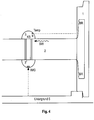
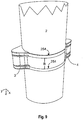
- Fig. 1 shows a simplified representation of a section of an embodiment of a device according to the invention.
- a wheel 1 for example a rail vehicle with a structure (not shown).
- a vehicle axle or the shaft 2 of a vehicle axle (in the context of the present invention often simplifying only referred to as a shaft) attached, which protrudes into the image plane, so that only their cross-sectional area is shown.
- the shaft 2 may typically connect two similar wheels 1 of the rail vehicle.
- a device 3 Arranged on the shaft 2 is a device 3 which may be designed according to different aspects of the invention described herein. In general, the device is arranged on the shaft rather than on other parts of the rail vehicle.
- the wheel 1 rolls in a forward or backward movement of the rail vehicle on the ground 5, which may for example be a rail.
- the device 3 a wide variety of sensors, for example.
- a partial or complete preprocessing of the received or acquired data can already take place within the device 3.
- the traveled distance (mileage), standstill, blockage of the wheels, speed, abnormal operating states (wear, derailment), track damage, shunting shocks and operating time, temperatures, positions, vehicle states, operating states, etc. can be determined.
- Fig. 2 shows a further simplified illustration of the embodiment according to Fig. 1 , Shown are the wheels 1 and a shaft 2 of a rail vehicle on which a device according to the invention is arranged according to an embodiment of the invention.
- the device 3 can be seen, which, as stated above, may include sensors and further electronic components for pre-processing and transmission of the data.
- the structure of the rail vehicle can be designed completely different, which is why the attachment of the device to the shaft is particularly advantageous.
- Fig. 3 shows a simplified block diagram of a device 3, as it may be attached to a shaft 2 of a rail vehicle.
- the device 3 can comprise different sensors and process, store and forward their signals to varying degrees.
- the sensors may in particular include an infrared sensor 256 for temperature measurement, a structure-borne sound sensor 257 for detecting the vibrations of the shaft, an acceleration sensor 21, a distance sensor 258, a GPS receiver 255 for position determination, a spatial filter sensor 253, depending on the implemented spatial filter function, a vibration sensor 252 and / or a reed sensor 251.
- the infrared sensor 256 may evaluate infrared signals so as to determine the temperature of the shaft, wheel 1 or other parts of the rail vehicle or the environment.
- An advantageous application of temperature measurement in combination with the infrared sensor is the detection of hot runners. A corresponding error message can then be stored by the device and / or transmitted to the outside. As a result, damage can be avoided.
- the infrared sensor can advantageously be pulsed and / or at intervals be operated to consume only low power.
- An infrared sensor can be advantageously used to image the brake disc.
- the structure-borne sound sensor 257 may generally serve to determine whether braking is taking place or not. This can be used to determine whether the journey is slowing down, for example due to an incline, or because it is being slowed down. When using the structure-borne sound sensor characteristic waves or spectra can be detected.
- the acceleration sensor 21 may be arranged in one, two and / or three directions (X, Y and Z-axis according to FIG Fig. 1 and 2 ) Measure static accelerations and outputs corresponding to three axes associated signals SX, SY and SZ (3-dimensional sensor). It may also be a 1- or 2-dimensional sensor in simplified embodiments. These are in the present embodiment, analog signals and are therefore first digitized in the analog-to-digital converter 22. The digitized sensor signals are then supplied to an evaluation logic 231, which is coupled to the analog-to-digital converter 22.
- the evaluation logic 231 or evaluation routine which in the simplest case is only suitable for storing the received sensor data in the data memory 24 and / or for transmitting this data by means of a radio module 27 via an antenna 29 to a further evaluation unit, can be hard-wired or embedded microcontroller System to be implemented (embedded microcontroller system).
- the device 3 may include an activation logic 25 and a motion detection 253 which ensure that the device is only turned on when needed.
- the activation logic 25 may be coupled to a reed sensor 251, which is excited to read or write data from or into the device 3 by means of an external field. That can happen when bringing a read / write device 12 (described later).
- the reed sensor 251 can in particular be activated by temporarily holding a magnet in the immediate vicinity (a few centimeters) to the mileage sensor 3.
- An advantage of using the Reed sensor is that it does not require any energy itself, only the activation logic consumes power. However, the current consumption of the activation logic 25 can be kept very low.
- the Reed Sensor is very cheap. It is non-contact and contactless and thus easily integrated into a robust housing. Another advantage can be achieved when a small distance between magnet and device 3 is set up for activation. This makes it possible, when several devices 3 are installed on a freight car to selectively activate only a specific device 3.
- the motion detection logic 253 may be advantageously coupled to a vibration sensor 252. Due to the long time of 6 to 7 years, which a device 3 should work autonomously, an adapted energy management is advantageous.
- a vibration sensor 252 should be designed as possible to equally detect shock in all directions. The power consumption should also be very low.
- An advantageous vibration sensor for use in the present embodiment may be a vibration sensor according to the ball-switching principle (ball-switch).
- the vibration sensor 252 may be coupled to a large series resistor to a voltage and coupled to a motion detection logic 253. This ensures that a flank is generated in a signal with every vibration. These edges are advantageously integrated (counted).
- An activation of the device 3 takes place only when a maximum number of flanks (vibrations) has been exceeded (eg within a certain time window). This can ensure that the activation is not too early, or too low vibrations due to a load of the rail vehicle takes place.
- the vibration can be stored in the form of a noise level or a maximum number of vibrations in the device as a parameter. As a result, specific vehicle or usage features can be taken into account.
- the acceleration sensor 21 is activated, which is used to determine the rotation of the shaft 2.
- it can be determined by whether the shaft 2 rotates and if there is a blockage of the wheels if necessary.
- a timing controller 28 for providing a time base may also be provided.
- a battery 26 provides the required energy, alternatively, of course, batteries, or other power generators can be provided that allow the longest autonomous operation of the device 3.
- Come advantageous Batteries that provide 8 Ah or 19 Ah. This is the case with C cells or D cells. This can be achieved with the device 3 according to the invention a running time of 6 to 7 years.
- the evaluation in the unit 23 can go beyond the buffering and / or transmission of the sensor data SX, SY, and / or SZ. It may be provided to perform certain evaluation steps already within the device 3, in order to reduce the amount of data for storage / transmission or to make a subsequent evaluation dispensable. For example, the number of revolutions of the wheels or the distance traveled could be immediately provided based on the sensor signals SX, SY and SZ. In addition, certain error signals (blockage of the wheels) could be calculated and / or transmitted with times, such as time and / or duration of the error. However, such an evaluation of the data can also take place in a separate evaluation unit, which is attached to the rail vehicle, or is provided stationarily outside the rail vehicle.
- An evaluation logic 231 can therefore provide in particular: speed calculation, direction detection, speed calculation, running power calculation, in combination with one or more errors, such as a jumper detector (eg with a limit of> 2.4 g), rail impact detector, flat-point detector, derailment detector and / or blocking detector.
- a jumper detector eg with a limit of> 2.4 g
- rail impact detector e.g., flat-point detector
- derailment detector e.g with a limit of> 2.4 g
- blocking detector e.g with a limit of> 2.4 g
- radio module 27 other interfaces can be provided which enable wireless or wired reading of the data of the acceleration sensor.
- GSM Global System for Mobile communications
- Bluetooth Wireless Fidelity
- UMTS Wireless Fidelity
- WLAN Wireless Fidelity
- the device can be preconfigured to different circumstances. Further, an alarm level 232 may be provided which triggers alarms when detected.
- the device 3 may be configured to receive and store important parameters. These include, for example, the wheel diameter (or radius) to calculate the mileage.
- various vehicle-specific parameters such as, for example, noise signal level or noise signal amplitude in the event of blockage of the wheels or derailment, history of the rail vehicle (already passed km or year of construction) can be written into the memory 24 of the device.
- maximum values for vertical or horizontal impacts eg 2.4 g, where g is the gravitational acceleration
- the device 3 can autonomously calculate specific rotation-specific and error-related variables and output the results. The output can be in the form of completed error codes and km values.
- the parameters and / or calculated values in the device 3 are protected against manipulation. For this encryption methods can be used.
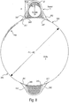
- Fig. 4 shows a section of a rail vehicle, are illustrated in the temperature measurement and use of an image sensor IMG.
- the device 3 is generally arranged on the shaft 2 of the vehicle axle of a rail vehicle. It moves with the shaft 2, whereby the device 3 thereby rotates around the shaft. This rotation is in accordance with the rotation of the wheel 1. If a hot runner in the axle bearing, this is determined by means of a temperature sensor TEMP.
- the temperature sensor may be an infrared sensor.
- the device 3 may advantageously also have a structure-borne sound sensor KS. This could detect sound waves SW, which are then evaluated. The actuation of the brake could then be acoustically detected by the sound waves SW through the shaft, as the actuation of the brakes causes typical acoustic patterns (spectra, harmonics, etc.). Other fault conditions or faulty conditions can also be detected by the structure-borne sound sensor.
- KS structure-borne sound sensor
- An image sensor IMG could also be provided on the shaft in the device according to the invention.
- the image sensor IMG could then receive an image or just a brightness signal of the background 5. It can be advantageously synchronized with the rotational movement of the shaft. This is achieved, for example, by evaluating signals of an acceleration sensor, as described in detail herein.
- the image of the background can then be evaluated in order to determine an absolute or, advantageously, only a relative position within a known route.
- the image sensor can, for example, only detect brightness values or specific color values. Detection can only take place when the sensor is oriented downwards towards the ground. As a result, energy can be saved and the spatial filtering can be simplified.
- the detected images (or even just image values, points, etc.) can then be compared to known patterns so as to determine the position.
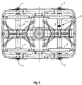
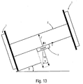
- Fig. 5 shows further aspects of the invention.
- the device 3 according to the invention is generally arranged on a shaft of a rail vehicle according to one or more aspects of the invention.
- the device 3 may contain one or more of the sensors mentioned above and later and corresponding evaluation and / or storage and / or wireless data transmission means.
- the device 3 is advantageously arranged in a rail vehicle with a bogie, as in Fig. 5 shown.
- the device 3 can not be arranged exactly in the middle M of the shaft 2. This provides more space in the rotation about the shaft 2.
- in this position is often advantageous visual connection to the bottom of the transport container of the rail vehicle. This allows, for example, advantageously the distance measurement for determining the loading condition.
- Devices 3 according to the invention can be arranged on one or more shafts 2 of the bogie.
- the suspension 7 is located outside the wheels. This is advantageously exploited because it provides a clear view of the device 3 on the wheels 1. This allows other measurements mentioned previously or later with the device 3.
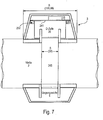
- Fig. 6 shows a further embodiment of the invention.
- a sensor for distance measurement 258 may be provided.
- This can be advantageously designed to determine the distance to the freight car underside or other known fixed parts of the shaft.
- ultrasonic transmitters and receivers come into consideration, which enable a distance measurement with ultrasound. However, they may not be able to withstand the given environmental conditions, and may not measure accurately enough during rotation. Therefore, advantageously, a radio-based sensor can be provided, as in Fig. 6 is shown.
- the transmitter arranged in the device 3 can emit pulse signals TX and measure their backscatter RX. From this, the distance DISTX between the bottom of the structure of the rail vehicle and the shaft 2 (or the device 3) can be measured.
- the distance measurement can be used to determine the loading state of the rail vehicle, for example a freight wagon. Due to the suspension 7 of a rail vehicle, the distance DISTX between a shaft 2 of the vehicle axle and the floor of the body reduces as the vehicle is loaded. Due to this, the distance to the load measurement can be used.
- the distance measurement can be synchronized with the rotational movement of the axle.
- the acceleration sensors may be used according to various aspects of the invention. As a result, the distance to a defined backscatter surface in a specific orientation of the shaft can advantageously be ascertained advantageously upwards.
- the attachment of a radar reflector, which generates a defined reproducible return signal, is also suitable here.
- Such a reflector generates by its, adapted to the radar frequency shape and size of a very powerful signal reflection.
- the return signal can be very well distinguished from reflections on other components of the car underside.
- the radar reflector may advantageously be mounted on the underside of the carriage above the shaft.
- the synchronization of the distance measurement with the rotational movement of the axis also leads to a reduction in the energy required for signal generation.
- Fig. 7 shows a simplified illustration of an embodiment of the invention.
- the device 3 is advantageously accommodated in a robust housing.
- the battery 26 (here, for example, a D cell) is to be arranged as close as possible to the shaft 2.
- the basic shape of the housing for the device 3 can be made wider on the shaft 2.
- the above aspects have beneficial effects on the forces that can be unusually high in the present application.
- the device 3 can be fastened by means of one or more circulating steel bands 245. This allows retrofitting with minimal time.
- the width B of the device 3 in the axial direction of the shaft can then advantageously not exceed 100 mm.
- a counterweight 4 is provided to compensate for the imbalance.
- the housing of the device 3 and the counterweight 4 have an approximately trapezoidal profile, or a wide base. Also a semicircular or arched profile comes into consideration. It is important to avoid torsional forces on the sensor module 3.
- the electronics may be mounted on the outside of the device 3. In this schematic representation, a board 241, the vibration sensor 252, a radio module 27 and an antenna 29 are shown as representative of the entire electronics.
- the vibration sensor 252 and antenna 29 are located in the part of the board overlapping the battery 26 on the inner side (facing the shaft) of the board 241.
- the memory (not shown) should be a non-volatile memory (eg EEPROM).
- the device 3 can advantageously be arranged in the middle of the shaft 2 or vehicle axle.
- Fig. 8 shows a section through the shaft 2 and the device 3 and the counterweight 4 to highlight further advantageous aspects of the invention.
- the housing for the device 3 and the counterweight 4 are rounded in the circumferential direction of the shaft 2 and thereby better adapt to the shaft circumference. Reinforcing struts 242 may be provided to accommodate torsional and other forces.
- the steel band 245 runs around the shaft 2 and through-throughs 243 of the housing for device 3 and counterweight 4.
- the board 241, the radio module 27 and the vibration sensor 252 are indicated.
- There is a part or all of the other electronics, as in Fig. 3 is shown.
- the adhesion between the shaft 2 and the circulating belt 245 should be selected so that no notch effect on the shaft 2 occurs. Damage to a lacquer layer on the shaft 2 should also be avoided.
- Another aspect is the corrosion between steel strip 245 and shaft 2. It may be advantageous to provide a further layer 244 between steel strip 245 and shaft 2, which is suitable for preventing corrosion.
- This layer 244 is illustrated illustratively only on a piece of the circumference of the shaft 2, but would run all the way around the shaft 2 under the steel strip 245.
- the shaft 2 facing side of the layer 244 could then have knobs or a tire tread. It could advantageously be designed so that a secure attachment is present, but which has no damage to the shaft result and retains as little moisture as possible.
- the support members 247 (like feet) are sloped to accommodate the curvature of the shaft. This increases the robustness and resistance to torsional, centrifugal and acceleration forces.
- the use of multiple inclined feet on the outside of the housing results in self-alignment of the sensor on the axle, which ensures during assembly that the measurement axes of the internal sensors are exactly parallel or orthogonal to the shaft.
- Fig. 9 shows a perspective embodiment of a further advantageous embodiment of a coupling of the device 3 with a shaft 2.
- two circumferential bands eg., Steel bands
- the configuration may be similar to the above.
- the size ratios can then be transferred to the two bands, wherein instead of the width S of the steel strip 254 in Fig. 8 , now the distance of the outer edges of the two steel bands is to be considered.
- Fig. 10 shows a perspective view of another advantageous embodiment of a coupling of a device 3 with a shaft 2.
- a closed circumferential sleeve is provided, in which the device 3 can be accommodated together with optional counterweight.
- the encircling case provides additional protection against stone chipping, abrasion, tampering, etc.
- the sleeve also provides torsional advantages.
- the steel bands 254 now run around outside the cuff once. Here now the distance of the steel strips with respect to the dimensions given above has to be considered.
- Fig. 11 shows a schematic side view of a rail vehicle 16 (wagon, railcar, etc.) with a device according to the invention and optional infrastructure for wireless and wired signal transmission and monitoring of the rail vehicle 16.
- the rail vehicle 16 has on a shaft 2, a device 3 and a counterweight 4.
- both waves shown 2 come into consideration.
- the device 3 may be configured as described herein.
- the data acquired by the device 3 and possibly pre-evaluated data can be sent to the control center 15 in various ways be transmitted.
- a mobile telematics unit 13 with radio communication devices can be arranged on the rail vehicle 16 and receive the sensor signals transmitted by the device 3 (eg mileage and possibly additional information or results of a preliminary evaluation, in particular an error code, time of a movement recording, etc.) via the radio link 17 and via a second radio link 20 to the center 15 transmit.
- the telematics unit 13 advantageously contains a microcontroller, a radio interface, memory, modules for GPS, GSM, Bluetooth and / or UMTS, a battery and / or a vibration sensor, and possibly numerous other sensors.
- a fixed radio communication device 14 which receive sensor signals via the radio link 18 and transmit via an additional wireless or wired communication link 19 to the center 15.
- the radio link 18 can also operate in accordance with common mobile radio standards (eg GSM or UMTS).
- the data can be centrally recorded and evaluated in the center 15.
- the data may be received via a wireless or wired communication link 11 from a mobile device 12.
- Via the communication links 17, 18 and 11 also parameters in the device 3 can be set and changed.
- the radio link 17 can advantageously use a high frequency range of 868 MHz or 2.4 GHz. This has also surprisingly proven to be useful in view of a complex infrastructure and complex readout and monitoring scenarios of numerous devices 3.
- the use of a lower radio frequency, specifically approved for railway operations, would be advantageous in terms of the propagation conditions of the waves in the freight wagon environment and possible interference by public users.
- the telematics unit 13 communicates with both devices 3 and 3A.
- To device 3A is the radio link 17A.
- the mobile device 12 can also contact the device 3A via the radio link 11A.
- the stationary radio communication device 14 which communicates with the second device via the radio link 18A.
- Each device 3 and 3A may be configured as described herein.
- the telematics unit 13 now differentiate between the devices 3 and 3A, and thus determine which signals (movement recording, mileage, speed, direction of rotation, blockage of the wheels, braking activity, etc.) come from which vehicle axle 2.
- the mileage of the freight wagon can be derived, for example, in the telematics unit 13 from the increment of the individual mileages.
- the review of the mileage and error history of the individual vehicle axles 2 is therefore particularly advantageous because the vehicle axles 2 can be replaced individually. Therefore, these vehicle axles 2 may have different mileages and fault histories from the vehicle. With regard to the safety and reliability of the rolling stock, this information is very important.
- the telematics unit 13 can transmit an alarm signal via radio to the central office. This allows errors to be detected quickly and, if necessary, corrected.
- a coding can be provided in the device. This can be unique and unchanging.
- the mobile device 12 may be configured to read a device 3, 3A as soon as it is close to the device 3, 3A to be read.
- the Reed sensor 251 (see. Fig. 3 ) are excited by means of a magnet and then the device to be read out are activated.
- the telematics unit 13 can be designed to check the position and, for example, the speed or also the direction of movement of the rail vehicle by means of GPS. This can be done occasionally to make a plausibility check of the data provided by the devices 3, 3A. In particular, to match the transmitted from the sensors speed signals with the current GPS speed. In addition, in case of error (For example, message: wheel blockade of a device) are also checked whether the rail vehicle really does not move. In addition, it can be located if necessary. Also, the telematics unit 13 may advantageously have a vibration sensor, which ensures that the telematics unit 13 is activated only when the rail vehicle moves. The autonomous running time of the telematics unit is advantageously up to 6 or 7 years.
- rotational motion detection and chassis diagnostics are possible by means of a compact, one-piece and sealed unit that can be easily retrofitted.
- the telematics unit 13 may poll the devices 3, 3A at regular time intervals rather than waiting for transmissions of the devices.
- telematics unit 13 and devices 3, 3A each have real-time clocks and can be synchronized with them. Then certain times can be provided for the transmission. In the event of an error (blockade, derailment), transmissions outside of the defined time intervals may also be provided, e.g. after the simultaneous response of the vibration sensors 252 in the devices and in the telematics unit 13 after a previous idle time.
- Fig. 12 shows a simplified representation of a section of an embodiment of a device according to the invention.
- a wheel 1 for example a rail vehicle (not shown).
- a vehicle axle or the shaft of a vehicle axle 2 (hereinafter often simply referred to simply as a shaft) attached, which protrudes into the image plane, so that only their cross-sectional area is shown.
- the shaft 2 may typically connect two similar wheels 1 of the rail vehicle.
- a unit 3 which comprises at least one motion sensor which can determine a static acceleration in at least one axis (direction).
- a counterweight 4 is arranged to avoid imbalance.
- the wheel 1 rolls in a forward or backward movement of the rail vehicle on the ground 5, which may for example be a rail.
- the axial Directions in which the accelerometer can detect the acceleration are indicated by an X, Y and a Z axis.
- the X, Y and Z axes are perpendicular to each other.
- the direction of earth gravity or gravitational field / gravitational acceleration is represented by an arrow 1G.
- the X axis points in the tangential direction with respect to the circumference of the cross section of the shaft 2, the Z axis in the radial direction from the center of the shaft 2 and the Y axis in the axial direction of the shaft 2, ie out of the image plane.
- a microprocessor In addition to the acceleration sensor, a microprocessor, a memory, in particular a semiconductor memory, and a radio module for transmitting data may be provided in the unit 3. In this respect, a partial or complete preprocessing of the signals determined with the acceleration sensor can already take place within the unit 3. Instead of a radio module, another interface may be provided, via which wireless or wired data from the unit 3 can be read out.
- a direction of rotation of the vehicle axle or shaft is indicated together with the angular velocity ⁇ .
- a rotation angle ⁇ is given with respect to the gravitational acceleration. The rotational angle ⁇ of the shaft 2 can be detected by the motion sensor.
- the speed, the angle of rotation, and / or the inclination of the shaft 2 possibly occurring irregularities on the rotating arrangement, irregularities on the ground and impacts by other objects can be detected.
- the sensor signals it is then possible to determine, inter alia, the distance traveled (mileage), standstill, blockage of the wheels, speed, abnormal operating states (wear, derailment), track damage, shunting shocks and operating time.
- the accelerometer measures the gravitational acceleration acting on the axle and on the sensor.
- An axis or shaft 2 rotating in the gravitational field of the earth produces, unless it is at 90 ° to the earth's surface, a periodic signal of the X and Z-axis sensor depending on the changing angle of rotation of the shaft 2.
- the frequency of the signal corresponds to the speed of the axis.
- At the center of the present invention are the evaluation of the time course of the sensor signals for determining the mileage or the driving speed and the detection of specific disturbances by an automated evaluation.
- Fig. 13 shows a further simplified illustration of the embodiment according to Fig. 12 , Shown are the wheels 1 and a shaft 2 of a rail vehicle on which a device according to the invention is arranged according to an embodiment of the invention.
- the unit 3 can be seen, which, as stated above, can also contain other electronic components for pre-processing and transmission of the data in addition to the acceleration sensor.
- the Y-axis points in the axial direction of the shaft 2. It allows a determination of the inclination of the shaft 2 relative to the horizontal.
- the X-axis points in the radial direction of the shaft, ie in or against the direction of rotation of the shaft.
- the Z-axis extends in the radial direction.
- the inclination angle is ⁇ .
- An evaluation unit according to the invention can thus be set up to also determine the inclination of the rail vehicle.
- FIGS. 14 to 20 show sensor signals SX and SZ for the axial directions X and Z, as they occur in a device 3 according to aspects of the invention and can be forwarded to the evaluation unit or a microcontroller.
- the evaluation unit 23 or the units 13, 14 or 15 according to Fig. 11 provide certain output signals or measurement results.
- the evaluation unit 23 or the units 13, 14 or 15 are arranged to evaluate the time course of the sensor signals SX, SZ (or even a third signal SY along a third axis with respect to the inclination of the vehicle axle, shaft 2) and from it mileage and / or to calculate speed and, if necessary, to detect error signals.
- Fig. 14 shows a diagram of a section with exemplary time profiles of two signals SX, SZ an acceleration sensor of a device 3 (as described above) with continuous forward travel of the vehicle. Shown is the temporal or related to the rotation angle ⁇ course of output signals SX, SZ of an acceleration sensor, which may be coupled to the vehicle axle 2 of a rail vehicle according to the invention.
- Fig. 14 refers to a continuous forward drive and gives the X-axis (SX) and the Z-axis (SZ) associated output signals SX, SZ again. These are periodic sinusoidal signals, which are superimposed with little interference.
- the signal SZ corresponding to the Z-axis has a speed-dependent offset (offset) compared with the signal SX assigned to the X-axis, here by way of example about 0.5 g (g is the gravitational acceleration).
- offset a speed-dependent offset
- the direction of the rotational movement can be taken from the phase shift of the X-axis associated signal SX with respect to the Z-axis associated signal SZ. In the present case, a forward drive is shown.
- Fig. 15 shows the signals according to Fig. 14 , in which Fig. 15 now concerns a reverse drive. Accordingly, the signal SZ associated with the Z axis leads the signal SX ahead of the X axis. At the same speed of the rail vehicle, however, the period or frequency of the signals remains constant. From the maximums of the signals, therefore, the speed and from the overall temporal course of the signals (or even only one of the signals) in an electronic evaluation, the completed mileage can be determined.
- Fig. 16 again shows one of Fig. 14 corresponding representation, wherein there is damage to a rotating part, so that at regular intervals peaks occur proportionally in both signals SX, SZ.
- peaks interference peaks or the like
- the periodicity indicates that the damage to a rotating part, eg flat spots, or defects in the bearing or running surfaces are present.
- the evaluation unit (for example, unit 23 or also one of the units 12, 13, 14, or 15) can be set up to derive from the sensor signals SX, SZ the concrete position of the damage to the wheel.
- the direction of impacts or acceleration values can be determined from the vectorial resultant of the acceleration values SX and SZ. Therefore, by means of a device according to the invention, a distinction can also be made between vertical and horizontal impacts. Taking into account the direction of the resulting acceleration values, different signal or error types (bearing damage, shunting shocks, load, etc.) can be differentiated, as further explained below.
- Fig. 17 again shows the signals SX, SZ according to Fig. 14 , where now a damage to the ground, such as on the rail, is present.
- Proportional acceleration values (outliers, glitches, etc.) occur singularly in the vertical direction in both axes. An automatic evaluation can thus be set up so that singular glitches or outliers are evaluated and output in the vertical direction as background damage.
- Fig. 18 shows the signals SX, SZ according to Fig. 14 , in the event of a collision in the longitudinal direction, eg when maneuvering.
- Proportional acceleration values (outliers, glitches, etc.) occur singularly in the horizontal direction in both axes.
- An automatic evaluation can thus be set up in such a way that the glitches of the signals are recognized as a longitudinal or jumpering impact.
- impacts of more than 2.4 g can be detected in a horizontal direction and output as an error, possibly with a time.
- Fig. 19 refers to a case where the rail vehicle is moved from a time tx but the wheels are locked.
- the output signals SX, SZ show non-periodic acceleration values (increased noise due to vibrations) from time tx, without a periodic signal (ie, the axis is rotating) being measured during this time.
- the occurrence of increased noise with simultaneous absence of the periodic rotation angle-dependent sinusoidal signal can thus be recognized as a blockage of the wheels.
- the evaluation can then store these signals, for example, with the time of occurrence and the duration of the occurrence.
- Fig. 20 finally shows the possible course of acceleration signals SX, SZ in case of derailment or permanent loss of wheel-rail contact.
- a continuous superimposition of the sinusoidal signal with disturbance variables in all axes, in some cases with a periodically recurring signature in the vertical direction, is determined with a constant time interval.
- An automatic detection of these signals would thus be possible on the basis of the features mentioned and could be detected in a correspondingly established evaluation unit. If necessary, an alarm signal could be triggered or at least the time could be recorded.
- the rotational speed of the vehicle axle 2 can also be determined or verified on the basis of the centrifugal force, that is to say the acceleration measured in the radial direction (Z-axis).
- This component is a DC signal as long as the speed remains constant.
- An evaluation unit according to the invention is then designed such that it performs the adjustment with this signal.
- certain specific simple error codes can be assigned to the errors or states.
- the following coding is advantageous: Table 1 code description 0x01 NN NN NN NN blockade 0x02 NN NN NN NN derailment 0x03 NN NN NN NN Horizontal push> 2.4 g 0x04 NN NN NN NN Damage to the rotating part 0x05 NN NN NN NN Damage to the ground 0xF1 NN NN NN NN Mileage (km) 0xF2 NN NN NN speed 0xF3 NN NN NN NN hot runner 0xF4 NN NN NN NN Faulty braking effect 0xF5 NN NN NN Brake tightened 0xF6 NN NN NN NN Load / mass
- the codes can be simple numerical codes of the error condition.
- a preamble with specific data (eg ID) of the device and encryption parameters can be prefixed.
- 'NN NN NN NN' are 4 bytes of user data.
- These can be next to the mileage or the indexed utility value also include a time stamp of the real-time clock.
- Table 1 illustrates some advantageous examples that are not exhaustive.
- the time stamp can be advantageously used to determine the car series.
- the states may relate to the actuation of the brake, which is based, for example, on the evaluation of signals from the structure-borne sound sensor. Likewise, signals of a temperature sensor for detecting a hot runner can be determined. Impacts can be detected by the acceleration sensors. Some states or errors are determined from combinations of sensor signals. For example. the acceleration or speed change with respect to a brake application, ie structure-borne noise. This can also apply to the temperature sensor.
- one-, two- or three-axis acceleration sensor is thus mounted on the vehicle axle or shaft of a vehicle, in particular a rail vehicle, which measures the acceleration values occurring in the direction of the X, Y and Z axes.
- the accelerometer is fixed to the axle and rotates with the axle around the center of the axle.
- the accelerometer measures the gravitational acceleration acting on the axle and on the sensor.
- An axis which rotates in the gravitational field of the earth produces a periodic signal of the X- and Z-axis sensor, unless it is at a 90 ° angle to the earth's surface, depending on the changing rotational angle of the axis.
- the frequency of the signal corresponds to the speed of the axis.
- at least one error signal can be detected.
- Fig. 21 illustrates an embodiment of the invention in terms of train composition and carriage series.
- a rail vehicle here is a train with N cars.
- the first car W1 may be a loco or, as shown here, a simple car.
- the train with the wagons W1, W2, W3, W4,... WN-1, WN-1, WN moves to the left at time 0.
- the car W1 starts to move at time TS1 (time stamp TS1).
- the third carriage W3 first starts at time TS3, the fourth car W4 at time TS4, the N-2th carriage WN-2 only at time TSN-2, the N-1th carriage WN-1 at time TSN-. 1 and the last car WN at time TSN.
- the time delays between each adjacent car do not have to be the same length in pairs. Nevertheless, the condition TSi ⁇ TSj always holds for i ⁇ j, where i, j are natural numbers. In this way, the order of the wagons can be determined, since from the point of view of the first moving wagon Wi, the following applies: POSi ⁇ POSj, for i ⁇ j, with i, j as previously defined. A smaller i, j then means a position closer to the top of the train at which the railcar is located. In a pure pushing movement, the relationships are of course exactly the opposite.
- the motion detection is carried out using a device 3, which is attached to a shaft 2 of the car W1 to WN in the manner previously described.
- the carriages W1 to WN can have a device 3 on each shaft 2 of their vehicle axles or only on one shaft 2. This is indicated by the numbering 1 to N on the wheels.
- the device 3 can advantageously have a rotation or movement sensor according to the above aspects and exemplary embodiments, in particular an acceleration sensor.
- POSX F TSX .
- POSX is the relative position of a rail vehicle (ie, a wagon within a train) and TSX is the relative or absolute startup time of the rail vehicle (ie, the wagon X within the train).
- This ID can be stored in the device 3.
- this ID can also be used to identify the car. It can then be a unique and unique number assigned to a single wave.
- identification numbers IDX may be assigned to cars, which may then also be stored in the device in the shaft. It can then advantageously be a read-only memory that stores the number.
- the values IDX or IDWX can be advantageously protected against unauthorized subsequent manipulation.
- the devices 3 on the shafts 1 to N of the carriages W1 to WN can also communicate with one another or at least send data from one to the next device.
- This may preferably be done by designing the devices 3 to build an ad hoc network.
- This network can spontaneously configure itself when assembling rail vehicles, especially trains with multiple cars. It may advantageously transmit data from a device 3 on a shaft of a car to an adjacent or at least spatially nearby device 3 on the shaft of another car. As a result, large distances can be bridged, which otherwise could only be overcome by increasing the transmission power of a single device. This can save power.
- the device 3 may provide the necessary protocols for authentication and authorization within a forming network.
- the device is advantageously set up in order to also provide the additionally required parameters for rail vehicles in addition to the conventional network properties.
- data can be entered into the device, which define the affiliation to a train. It is also possible to enter parameters relating to a wagon of a train. These can be linked to one or more IDs of the wagon or wagons of wagons and stored permanently.
- a device 3 may have a unique unique ID associated with the shaft 2 of a rail vehicle. As a result, properties of the shaft 2 can be monitored and investigations can be used. Manipulation is only possible if the device is removed, which in turn by sealing with the shaft of the vehicle axle, as described above can be prevented.
- Fig. 11 described wirelessly with different other devices 12, 14 done. These can be provided as a telematics unit 14 or else telematics units 14 on each car or in the outside of the train as handsets 12 or even fixed devices 12.
- the devices 12, 14 can then take over part of the evaluation of the signals or receive the finished data from the devices 2.
- the devices 3, 12, 14 can be integrated into an infrastructure as they relate Fig. 11 has been described. In particular, then the wagon ranking information can be utilized advantageously within the infrastructure.
- a device 3 is further configured to determine the natural resonance frequency of a shaft 2.
- these structure-borne sound sensors or other acoustic sensors may include in order to detect a shift of a natural resonance frequency of the shaft 2.
- the excitation caused by the operation of the shaft 2 is preferably used to determine the shift of the natural resonance frequency.
- the device 3 may in particular be designed to analyze the shift of the natural resonance frequency with regard to possible errors or dangers.
- the device 3 may comprise an evaluation unit which detects a faulty shaft 2, in particular a cracking of the shaft 2, on the basis of the displacement of the natural resonance frequency. In particular, such a detection of faults on each shaft of a rail vehicle can take place.
- the evaluation can be communicated via the telematics and radio units or stored within the devices. Accordingly, alarm signals can be triggered when threshold values are exceeded.
- the device 3 according to the invention can also be designed to carry out a damage analysis by evaluating the modulation of the natural frequency of the shaft 2 with the rotational frequency of the shaft 2.
- no external excitation of the vibrations is required. Instead, the Evaluation during operation. The excitation then takes place, for example, by unevenness on the running surfaces and / or the rails.
- suggestions during loading and unloading, maneuvering, by driving over unevenness and / or turnouts can be triggered and these are automatically analyzed within the device 3 according to the invention to a shift in the natural frequency. If the device 3 has acceleration sensors or structure-borne sound microphones, these can be designed to record such natural oscillations.
- the analysis of the oscillation can take place directly in the device 3, where a shift of the natural frequency can be detected there.
- a deviation from a setpoint value of the natural frequency can be reported to a central station or stored within the device by stating the identification of the device 3 or the shaft 2 or of the wheelset or of the car via radio communication. It has been shown that damage, for example arising on the shaft 2, can change the spectrum of the natural frequency of the shaft 2. By comparison with a target spectrum, it can be used to warn at an early stage of further damage and the resulting dangers.
- the shaft 2 is generally subject to a bending load. This arises in particular by offset attack points of the load to be supported by the shaft 2, but also by the weight of the shaft 2 itself. It has been shown that the bending load of the shaft 2 changes the natural frequency of the shaft 2. In a device 3 according to this embodiment of the invention, this effect can be exploited to determine, for example, the weight of the current payload of a rail vehicle or a freight car. The greater the weight of the payload, the greater the bending load in the shaft 2 and thus the shift of the natural frequency. This is especially true for an undamaged shaft. In the case of a faulty wave (for example, cracking), a change in the natural frequency spectrum can be detected in addition to the shift in the natural frequency.
- a faulty wave for example, cracking
- the natural frequency spectrum of the shaft 2 is modulated with the rotational frequency of the shaft 2.
- the inventive device 3 according to this embodiment may be particularly advantageously designed to this modulation of the natural frequency spectrum be detected and used to detect a fault on the shaft (for example, cracking).
Landscapes
- Engineering & Computer Science (AREA)
- Mechanical Engineering (AREA)
- Transportation (AREA)
- Health & Medical Sciences (AREA)
- Biomedical Technology (AREA)
- General Health & Medical Sciences (AREA)
- Physics & Mathematics (AREA)
- General Physics & Mathematics (AREA)
- Electric Propulsion And Braking For Vehicles (AREA)
- Regulating Braking Force (AREA)
- Arrangements For Transmission Of Measured Signals (AREA)
- Measurement Of Length, Angles, Or The Like Using Electric Or Magnetic Means (AREA)
Priority Applications (1)
| Application Number | Priority Date | Filing Date | Title |
|---|---|---|---|
| PL09763838T PL2432669T3 (pl) | 2008-11-19 | 2009-11-18 | Urządzenie i sposób dla pojazdu szynowego |
Applications Claiming Priority (3)
| Application Number | Priority Date | Filing Date | Title |
|---|---|---|---|
| DE102008057966 | 2008-11-19 | ||
| DE102009020428A DE102009020428A1 (de) | 2008-11-19 | 2009-05-08 | Vorrichtung und Verfahren für ein Schienenfahrzeug |
| PCT/EP2009/008211 WO2010057623A2 (de) | 2008-11-19 | 2009-11-18 | Vorrichtung und verfahren für ein schienenfahrzeug |
Publications (2)
| Publication Number | Publication Date |
|---|---|
| EP2432669A2 EP2432669A2 (de) | 2012-03-28 |
| EP2432669B1 true EP2432669B1 (de) | 2019-03-27 |
Family
ID=42105295
Family Applications (1)
| Application Number | Title | Priority Date | Filing Date |
|---|---|---|---|
| EP09763838.1A Active EP2432669B1 (de) | 2008-11-19 | 2009-11-18 | Vorrichtung und verfahren für ein schienenfahrzeug |
Country Status (10)
| Country | Link |
|---|---|
| US (2) | US9211879B2 (pl) |
| EP (1) | EP2432669B1 (pl) |
| CN (1) | CN102333687B (pl) |
| AU (1) | AU2009317576B2 (pl) |
| CA (1) | CA2744287C (pl) |
| DE (1) | DE102009020428A1 (pl) |
| PL (1) | PL2432669T3 (pl) |
| RU (1) | RU2524805C2 (pl) |
| WO (1) | WO2010057623A2 (pl) |
| ZA (1) | ZA201103698B (pl) |
Cited By (2)
| Publication number | Priority date | Publication date | Assignee | Title |
|---|---|---|---|---|
| WO2023041766A1 (de) * | 2021-09-20 | 2023-03-23 | Zf Friedrichshafen Ag | Verfahren zum erkennen einer beschädigung an einem transportsystem und steuereinrichtung dafür |
| EP4321399A1 (en) * | 2022-08-12 | 2024-02-14 | Volvo Truck Corporation | A method for flat-spot detection |
Families Citing this family (115)
| Publication number | Priority date | Publication date | Assignee | Title |
|---|---|---|---|---|
| DE102009053801B4 (de) * | 2009-11-18 | 2019-03-21 | Knorr-Bremse Systeme für Schienenfahrzeuge GmbH | Verfahren und Einrichtung zur Zustandsüberwachung wenigstens einen Radsatz aufweisenden Drehgestells eines Schienenfahrzeugs |
| DE102010038551A1 (de) * | 2010-07-28 | 2012-02-02 | Aktiebolaget Skf | Gehäusebauteil für eine Radlagereinheit eines Schienenfahrzeugs und Radlagereinheit für ein Schienenfahrzeug |
| US8751045B2 (en) * | 2010-07-29 | 2014-06-10 | Taiwan Semiconductor Manufacturing Company, Ltd. | System and method of monitoring an environmental parameter along a predetermined route |
| CN101975670B (zh) * | 2010-09-08 | 2012-06-06 | 同济大学 | 铁路轮对制动特性模拟装置 |
| EP2450250A1 (en) * | 2010-09-14 | 2012-05-09 | Thales Deutschland GmbH | Power supply for a goods wagon and train integrity system for a cargo train |
| DE102011113083A1 (de) * | 2011-09-09 | 2013-03-14 | Knorr-Bremse Systeme für Schienenfahrzeuge GmbH | Bremssteuereinrichtung für eine Bremsanlage eines Schienenfahrzeuges, Bremsanlage, Schienenfahrzeug und Verfahren zum Durchführen einer Funktionsdiagnose |
| DE102011113026A1 (de) * | 2011-09-09 | 2013-03-14 | Knorr-Bremse Systeme für Schienenfahrzeuge GmbH | Bremssteuereinrichtung für eine Bremsanlage, Bremsanlage, Schienenfahrzeug sowie Verfahren zum Betreiben einer Bremsanlage |
| US10017015B2 (en) | 2011-09-30 | 2018-07-10 | Infineon Technologies Ag | Method for detecting wheel rotation using a one-dimensional acceleration sensor |
| US8646167B2 (en) * | 2012-01-12 | 2014-02-11 | Sauer-Danfoss Inc. | Method of actuating a wireless sensor of road construction equipment |
| US20130269453A1 (en) * | 2012-03-27 | 2013-10-17 | Cut Coal Technology Holdings Pty Ltd | Method and system for determining structural changes in a longwall mine |
| EP2650190A1 (en) | 2012-04-12 | 2013-10-16 | Progress Rail Services Corporation | Device for detecting a hot box or hot wheel condition |
| CN104271428B (zh) * | 2012-04-25 | 2017-12-15 | 西门子公司 | 用于调查轮轨接触的方法 |
| DE102012009348A1 (de) * | 2012-05-09 | 2013-11-14 | Db Schenker Rail Deutschland Ag | Verfahren und Vorrichtung zum Erfassen und Auswerten von Daten bezüglich des Zustands der Hauptluftleitung eines Fahrzeugverbandes |
| FR2991042B1 (fr) * | 2012-05-25 | 2014-06-27 | Alstom Transport Sa | Procede d'evaluation du diametre d'une roue, et ensemble d'evaluation associe |
| US8925872B2 (en) | 2012-05-31 | 2015-01-06 | Electro-Motive Diesel, Inc. | Consist communication system having bearing temperature input |
| DE102012015020A1 (de) * | 2012-07-28 | 2013-10-17 | Eisenmann Ag | Industrielle Förderanlage und Verfahren zum Betreiben einer solchen |
| US10775271B2 (en) * | 2012-08-22 | 2020-09-15 | Ge Global Sourcing Llc | System for determining conicity of a wheel based on measured vibrations |
| DE102012108171A1 (de) | 2012-09-03 | 2014-03-06 | Knorr-Bremse Systeme für Schienenfahrzeuge GmbH | Stillstandsermittlung bei einem Schienenfahrzeug |
| DE102012217721A1 (de) | 2012-09-28 | 2014-04-03 | Siemens Aktiengesellschaft | Vorrichtung für ein Schienenfahrzeug |
| DE102012109670B4 (de) | 2012-10-11 | 2018-03-08 | Infineon Technologies Ag | System und Verfahren zur Bestimmung der Reifenlaufleistung und Reifenabnutzung |
| DE102012221856A1 (de) * | 2012-11-29 | 2014-06-05 | Leonhard Weiss Gmbh & Co. Kg | System und Verfahren zur Erfassung einer Flachstellenbildung an zumindest einem Radreifen |
| DE102013201289B4 (de) * | 2013-01-28 | 2018-03-15 | Siemens Aktiengesellschaft | Verfahren zum Erkennen eines Schwingens in einem Schienenfahrzeug |
| US9821824B2 (en) * | 2013-01-29 | 2017-11-21 | Mitsubishi Heavy Industries, Ltd. | Vehicle and track transportation system |
| CN103205920A (zh) * | 2013-04-03 | 2013-07-17 | 中铁第四勘察设计院集团有限公司 | 铁路轨道几何形态检测方法 |
| DE102013206997A1 (de) * | 2013-04-18 | 2014-11-06 | Voith Patent Gmbh | Überwachungssystem |
| EP2808223A1 (en) * | 2013-05-28 | 2014-12-03 | IRCOi BVBA | System for monitoring one or more axles present beneath an unpowered transport unit |
| RU2015149644A (ru) * | 2013-06-05 | 2017-07-17 | Сименс Аг Эстеррайх | Ось колесной пары для рельсовых транспортных средств |
| DE102013213808A1 (de) * | 2013-07-15 | 2015-01-15 | Siemens Aktiengesellschaft | Schwingungserfassungssystem, Fahrzeug und Verfahren zur Schwingungserfassung |
| RU2536774C1 (ru) * | 2013-07-19 | 2014-12-27 | Открытое акционерное общество "Всероссийский дважды ордена Трудового Красного Знамени теплотехнический научно-исследовательский институт" | Система диагностирования технического состояния вала или валопровода роторной машины с использованием контактных датчиков абсолютной вибрации |
| WO2015020062A1 (ja) * | 2013-08-06 | 2015-02-12 | ナブテスコ株式会社 | 鉄道車両用ブレーキシステム、鉄道車両用ブレーキ制御装置、および、鉄道車両用ブレーキ制御方法 |
| DE102013218040A1 (de) * | 2013-09-10 | 2015-03-12 | Siemens Aktiengesellschaft | Verfahren sowie Vorrichtung zum Erkennen einer Positionsänderung eines zumindest teilweisen abgeschalteten Fahrzeugs |
| DE102014000641A1 (de) * | 2014-01-16 | 2015-07-16 | Innotec Lightweight Engineering & Polymer Technology Gmbh | Radsatzwelle und Radsatz sowie Verfahren zu ihrer Herstellung |
| DE102014201729A1 (de) * | 2014-01-31 | 2015-08-06 | Siemens Aktiengesellschaft | Schienenfahrzeug |
| KR101551972B1 (ko) | 2014-02-25 | 2015-09-18 | 현대자동차주식회사 | Esc 시스템을 이용한 브레이크 마찰재 마모 경고 시스템 |
| CN104370216A (zh) * | 2014-10-31 | 2015-02-25 | 芜湖三六机械有限公司 | 一种报警刹车动作装置 |
| DE102014226907A1 (de) * | 2014-12-23 | 2016-07-07 | Siemens Aktiengesellschaft | Kommunikationsaufbau und Datenübertragung in einem Schienenfahrzeug |
| US9718452B2 (en) * | 2015-03-11 | 2017-08-01 | General Electric Company | Brake monitoring system and method |
| DE102015205535A1 (de) * | 2015-03-26 | 2016-09-29 | Siemens Aktiengesellschaft | Bestimmen der Position eines Fahrzeugs |
| CN105015524B (zh) * | 2015-07-09 | 2017-11-10 | 中车株洲电力机车研究所有限公司 | 一种多辆编组列车制动力分配方法及系统 |
| RU2611469C2 (ru) * | 2015-07-20 | 2017-02-22 | Федеральное государственное бюджетное образовательное учреждение высшего профессионального образования "Уфимский государственный авиационный технический университет" | Способ и устройство контроля самопроизвольного трогания поезда |
| AU2016359179A1 (en) * | 2015-11-24 | 2018-06-28 | Electric Power Research Institute, Inc. | Apparatus and methods for direct sensing of rotational dynamics of a rotating shaft |
| EP3556636A3 (en) * | 2015-12-18 | 2019-12-18 | General Electric Company | Sensor signal processing system and method |
| CN105372080B (zh) * | 2015-12-22 | 2018-04-24 | 成都市新筑路桥机械股份有限公司 | 一种有轨电车及其嵌入式轨道耦合动力学测试装置及方法 |
| GB2546087A (en) * | 2016-01-07 | 2017-07-12 | Skf Ab | Railway condition monitoring sensor device and method for monitoring the condition of a railway bearing |
| CN105547451A (zh) * | 2016-01-22 | 2016-05-04 | 华东交通大学 | 一种高速列车车轮空间耦合振动测试的新方法 |
| JP2017161479A (ja) * | 2016-03-11 | 2017-09-14 | 株式会社東芝 | 無線装置、通信方法およびプログラム |
| US10866195B2 (en) * | 2016-04-08 | 2020-12-15 | Canadian National Railway Company | Wheel integrity monitoring system |
| DE102016005861B4 (de) * | 2016-05-12 | 2020-12-10 | Audi Ag | Fahrzeug mit einer Bremsanlage |
| FR3052709B1 (fr) * | 2016-06-17 | 2018-07-06 | Continental Automotive France | Procede de detection et d'estimation d'un angle de rotation sur elle-meme d'une unite roue avec capteur d'acceleration radiale integre |
| DE102016009600A1 (de) * | 2016-08-09 | 2018-02-15 | Carl Krafft & Söhne GmbH & Co. KG | Verfahren zum Erfassen von Nutzungsdaten von Walzen |
| CN106131218A (zh) * | 2016-08-24 | 2016-11-16 | 中国神华能源股份有限公司 | 一种铁路确报装置及系统 |
| DE102016116419A1 (de) | 2016-09-02 | 2018-03-08 | Knorr-Bremse Systeme für Schienenfahrzeuge GmbH | Verfahren und Vorrichtung zum Überwachen von Fahrzeugzuständen in Schienenfahrzeugen |
| DE102016220500A1 (de) * | 2016-10-19 | 2018-04-19 | Robert Bosch Gmbh | Vorrichtung und Verfahren zur Überprüfung eines Rads eines Schienenfahrzeugs auf Flachstellen |
| US20180122161A1 (en) * | 2016-11-03 | 2018-05-03 | Ross Bolton | Combination model vehicle commercial off the shelf performance characteristics system |
| DE102016225516B4 (de) * | 2016-12-20 | 2019-11-14 | Bayerische Motoren Werke Aktiengesellschaft | Messsystem und Messverfahren für ein Fahrzeug |
| CN106679999B (zh) | 2016-12-26 | 2018-11-23 | 合肥工大高科信息科技股份有限公司 | 一种车厢内置式高速列车走行部件在线故障检测装置 |
| AT519490B1 (de) | 2016-12-30 | 2020-01-15 | Avl List Gmbh | Kommunikation eines Netzwerkknotens in einem Datennetz |
| DE102017101545B4 (de) | 2017-01-26 | 2025-01-30 | Infineon Technologies Ag | Sensorsteuereinheit, Sensorsignalempfänger, ein Modul mit inkrementellem, magnetischem Geschwindigkeitssensor, ein Verfahren für eine Sensorsteuereinheit, ein Verfahren für einen Sensorsignalempfänger und Computerprogramm |
| DE102017102074A1 (de) * | 2017-02-02 | 2018-08-02 | Knorr-Bremse Systeme für Nutzfahrzeuge GmbH | Schnittstellenelement für ein Fahrzeug |
| CZ307759B6 (cs) * | 2017-02-06 | 2019-04-17 | Level, S.R.O. | Zařízení na monitorování provozních parametrů osy vozidla |
| JP6867826B2 (ja) * | 2017-02-23 | 2021-05-12 | 三菱重工エンジニアリング株式会社 | 異常監視装置、異常監視方法およびプログラム |
| US10525945B2 (en) * | 2017-04-18 | 2020-01-07 | Goodrich Corporation | Antiskid brake control system with axle-mounted inertial sensor |
| DE102017108363B4 (de) | 2017-04-20 | 2022-10-06 | Saf-Holland Gmbh | Achsüberwachungssystem eines Fahrwerkes eines Nutzfahrzeuges und Verwendung eines Achsüberwachungssystems |
| AT519966B1 (de) * | 2017-05-05 | 2018-12-15 | Pj Messtechnik Gmbh | Verfahren zur Durchführung einer automatischen Bremsprobe an einem Zug und dazu ausgebildeter Wagen |
| IT201700050006A1 (it) * | 2017-05-09 | 2018-11-09 | Faiveley Transport Italia Spa | Sistema e procedimento per il rilevamento di una condizione di andatura anomala di un carrello di un veicolo ferroviario. |
| US20230058093A1 (en) * | 2017-05-09 | 2023-02-23 | Faiveley Transport Italia S.P.A. | Vehicle control system |
| EP3401567A1 (en) * | 2017-05-10 | 2018-11-14 | Ovinto cvba | Monitoring of cargo wagon brake pads |
| CN107181454B (zh) * | 2017-05-26 | 2023-03-21 | 重庆科技学院 | 路径延长轨道及其太阳能板间连接轨道 |
| DE102017119991B4 (de) | 2017-08-31 | 2020-11-26 | Knorr-Bremse Systeme für Schienenfahrzeuge GmbH | Verfahren und Einrichtung zur Ermittlung von bremsungsrelevanten IST-Werten eines Schienenfahrzeuges für die Durchführung einer verzögerungsgeregelten Bremsung mit verteilter Sensorik |
| JP6991342B2 (ja) | 2017-09-19 | 2022-02-03 | シーメンス アクチエンゲゼルシヤフト | 台車軌道モニタリング |
| DE102017218006A1 (de) * | 2017-10-10 | 2019-04-11 | Eidgenössische Technische Hochschule Zürich | Bewegungsermittlungseinrichtung mit Beschleunigungssensor mit beweglicher Aufhängung |
| DE102017218056A1 (de) * | 2017-10-10 | 2019-04-11 | Knorr-Bremse Gmbh | Aktive Regelung eines Stromabnehmers |
| DE102017221107A1 (de) * | 2017-11-24 | 2019-05-29 | Knorr-Bremse Systeme für Schienenfahrzeuge GmbH | Unterdrückung der Meldungen auf einem Fahrzeug in Kombination mit geografischen Koordinaten und bestimmten Zeiten (Zeitstempel) |
| US10836407B2 (en) | 2017-11-29 | 2020-11-17 | Sperry Rail Holdings, Inc. | System and method for inspecting a rail |
| EP3720743B1 (en) * | 2017-12-04 | 2022-01-19 | Faiveley Transport Italia S.p.A. | A system for determining an angular speed of an axle of a railway vehicle and corresponding method |
| CN107947824B (zh) * | 2017-12-18 | 2019-12-17 | 成都理工大学 | 一种振动和无线双冗余应急通信的设备 |
| FR3075144B1 (fr) * | 2017-12-20 | 2025-03-07 | Alstom Transp Tech | Vehicule ferroviaire, systeme ferroviaire et procede de composition de vehicule ferroviaire associes |
| EP3517927B1 (de) * | 2018-01-24 | 2020-11-18 | Vibro-Consult AG | Verfahren und vorrichtung zur früherkennung eines risses in einem radsatz für ein schienenfahrzeug |
| CN108407849A (zh) * | 2018-04-04 | 2018-08-17 | 中车青岛四方机车车辆股份有限公司 | 一种测速定位系统的试验台 |
| RU2721219C2 (ru) * | 2018-05-23 | 2020-05-18 | Акционерное общество "Научно-исследовательский институт железнодорожного транспорта" | Устройство мониторинга рельсового транспортного средства |
| CN108945003A (zh) * | 2018-08-01 | 2018-12-07 | 中车齐齐哈尔车辆有限公司 | 一种铁路货运列车故障检测方法、装置和系统 |
| AT521877B1 (de) * | 2018-10-31 | 2023-12-15 | Siemens Mobility Austria Gmbh | Verfahren und Vorrichtung zur Detektion eines Entgleisungszustands eines Schienenfahrzeugs |
| EP3939742B1 (en) * | 2019-03-29 | 2024-12-25 | Hirata Corporation | Measurement device |
| CN110171450A (zh) * | 2019-06-12 | 2019-08-27 | 中国神华能源股份有限公司 | 判定固定编组列车欠编混编的方法及装置 |
| EP3792141A1 (en) * | 2019-09-13 | 2021-03-17 | Nabtesco Corporation | Railway condition monitoring device |
| US10852158B1 (en) | 2019-09-27 | 2020-12-01 | Kitty Hawk Corporation | Distance sensor test system |
| EP3816633A1 (en) * | 2019-10-29 | 2021-05-05 | ALSTOM Transport Technologies | System for detecting the velocity of a vehicle comprising at least a piezoelectric element fixed to at least one wheel and at least one additional sensor, and associated method and computer program |
| CN112849217B (zh) * | 2019-11-27 | 2022-12-06 | 中车唐山机车车辆有限公司 | 轨道列车异常振动信号的处理系统 |
| DE102020200568A1 (de) * | 2020-01-17 | 2021-07-22 | Mtu Friedrichshafen Gmbh | Verfahren zum Überwachen der Funktionsfähigkeit eines Fahrzeugs, Steuerung für einen Antrieb eines Fahrzeugs, Antrieb mit einer solchen Steuerung, und Fahrzeug mit einem solchen Antrieb |
| EP4121335A4 (en) | 2020-03-20 | 2024-04-10 | Amsted Rail Company, Inc. | APPARATUS AND METHODS FOR MONITORING MOBILE RAIL ASSETS |
| CN111447004B (zh) * | 2020-03-26 | 2022-03-04 | 航天恒星科技有限公司 | 导航增强数据的播发系统和方法 |
| JP2021185350A (ja) * | 2020-05-25 | 2021-12-09 | ソニーセミコンダクタソリューションズ株式会社 | 信号処理装置、および信号処理方法、並びにプログラム |
| GB2596514B (en) * | 2020-06-08 | 2024-05-15 | Hitachi Rail Ltd | Defect detection |
| CN111693304B (zh) * | 2020-06-19 | 2021-06-25 | 西南交通大学 | 车辆故障检测方法、装置、计算机设备和可读存储介质 |
| WO2022006614A1 (en) * | 2020-07-09 | 2022-01-13 | Central Queensland University | Method and system for improving braking performance of a rail vehicle |
| DE102020208955A1 (de) * | 2020-07-17 | 2022-01-20 | Siemens Mobility GmbH | Verfahren zum Überwachen eines Gefahrenraumes und Überwachungsvorrichtung |
| CN112229655B (zh) * | 2020-09-25 | 2022-09-02 | 中车长春轨道客车股份有限公司 | 一种轨道列车调试布局及轨道列车动态调试工艺 |
| CN112061181B (zh) * | 2020-09-28 | 2022-06-03 | 广东博智林机器人有限公司 | 位置检测装置及运输车 |
| DE102020127311A1 (de) | 2020-10-16 | 2022-04-21 | BEN-INNOVA Systemtechnik GmbH | Vorrichtung zur Festbrems- und/oder Heißläuferortung bei Schienenfahrzeugen und System mit einer Vorrichtung zur Festbrems- und/oder Heißläuferortung und zumindest einer Schwelle zur Auflage von Schienen |
| DE102021202894A1 (de) * | 2021-03-24 | 2022-09-29 | Siemens Mobility GmbH | Verfahren zur Überwachung einer Ruheabschaltung eines Schienenfahrzeugs |
| SE544933C2 (en) * | 2021-04-23 | 2023-01-10 | Bae Systems Haegglunds Ab | Method and device for determining potential damage of an endless track of a tracked vehicle |
| CN113739899A (zh) * | 2021-09-07 | 2021-12-03 | 济南沃成电子科技有限公司 | 一种高速铁路轨道振动实时检测装置及其使用方法 |
| US11982585B2 (en) * | 2021-09-23 | 2024-05-14 | Rockwell Automation Technologies, Inc. | System and method for strain and acceleration based analytics in an independent cart system |
| TWI828177B (zh) * | 2022-06-02 | 2024-01-01 | 博誠電子股份有限公司 | 即時車輛狀態感測系統 |
| CN119546499A (zh) * | 2022-06-21 | 2025-02-28 | 法伊韦利传送器意大利有限公司 | 验证至少一个车辆的至少一个制动装置的操作的方法及相应的验证系统 |
| EP4303088B1 (en) | 2022-07-04 | 2024-08-28 | Dellner Bubenzer AB | Controller for estimating individual axle weights of a rail vehicle, computer-implemented method therefor, computer program and non-volatile data carrier |
| CN115214592B (zh) * | 2022-07-13 | 2024-05-10 | 北京主导时代科技有限公司 | 一种轨道车辆制动机检测装置 |
| DE102022207597A1 (de) * | 2022-07-26 | 2024-02-01 | Zf Friedrichshafen Ag | Ermitteln eines Raddurchmessers eines Schienenfahrzeugs |
| JP2024020970A (ja) * | 2022-08-02 | 2024-02-15 | 日本無線株式会社 | アンテナ劣化判断装置及びアンテナ劣化判断プログラム |
| EP4331927B1 (en) | 2022-09-02 | 2024-11-20 | Dellner Bubenzer AB | Controller for estimating axle weights of a rail vehicle, computer-implemented method therefor, computer program and non-volatile data carrier |
| US11713064B1 (en) * | 2022-09-20 | 2023-08-01 | Bnsf Railway Company | System and method for detecting axle body and filet cracks in rail vehicles |
| CN116593906B (zh) * | 2023-03-03 | 2026-03-10 | 宇通客车股份有限公司 | 一种车辆及其电池箱性能监测方法、系统 |
| EP4431365B1 (de) * | 2023-03-17 | 2025-02-12 | Baumer Electric AG | Drehgeber zur störstellendetektion sowie zug mit einem drehgeber |
| CN116534074A (zh) * | 2023-05-06 | 2023-08-04 | 北京可维汇众科技发展有限公司 | 一种地铁轮轨伤损在线检测方法、装置及系统 |
| DE102023205859B4 (de) * | 2023-06-22 | 2026-01-15 | Zf Friedrichshafen Ag | Verfahren zur Bestimmung einer Zugkonfiguration |
Family Cites Families (20)
| Publication number | Priority date | Publication date | Assignee | Title |
|---|---|---|---|---|
| US2024669A (en) * | 1933-12-07 | 1935-12-17 | Westinghouse Air Brake Co | Speed controlled brake |
| FR1076317A (fr) * | 1953-03-10 | 1954-10-26 | Tecalemit | Mécanisme commandé par la différence des vitesse de rotation de deux arbres et son application aux dispositifs anti-enrayeurs |
| ES2037484T3 (es) | 1989-04-05 | 1993-06-16 | Inventio Ag | Procedimiento para el examen y la vigilancia de frenos en vehiculos sobre carriles y dispositivo para la ejecucion del procedimiento. |
| US6006868A (en) * | 1996-11-14 | 1999-12-28 | Technical Services And Marketing Inc. | System for monitoring brake status on a rail car |
| FR2782794B1 (fr) * | 1998-05-18 | 2000-11-17 | Alsthom Gec | Ensemble de detection, dispositif de mesure muni de cet ensemble et procedes de controle de ces ensemble et dispositif |
| IT1303083B1 (it) * | 1998-07-27 | 2000-10-30 | Skf Ind Spa | Dispositivo per il montaggio di un sensore ad un gruppo cuscinetto diun assile ferroviario. |
| DE19858922C1 (de) | 1998-12-19 | 2000-07-06 | Deutsche Bahn Ag | Verfahren zum Bestimmen der physischen Reihenfolge von Fahrzeugen eines zusammengestellten Zuges und Anordnung zur Durchführung des Verfahrens |
| IT1320400B1 (it) * | 2000-06-06 | 2003-11-26 | Skf Ind Spa | Metodo ed apparecchiatura per rilevare difetti di rotondita'in unaruota di un veicolo ferroviario. |
| AT410925B (de) * | 2000-10-12 | 2003-08-25 | Siemens Sgp Verkehrstech Gmbh | Verfahren und vorrichtung zur bestimmung des raddurchmessers und/oder der fahrtgeschwindigkeit eines schienenfahrzeuges |
| DE10107571A1 (de) * | 2000-11-09 | 2002-05-23 | Alcatel Sa | System zur Überprüfung der Vollständigkeit eines Fahrzeugverbundes |
| DE10233844B4 (de) | 2002-07-25 | 2007-06-14 | Knorr-Bremse Systeme für Schienenfahrzeuge GmbH | Vorrichtung und Verfahren zur Überwachung des Funktions- und/oder Verschleißzustandes von Bremsbelägen und Bremsscheiben einer Fahrzeugbremse |
| JP4827412B2 (ja) | 2002-09-05 | 2011-11-30 | ボンバルディール トランスポーテイション ゲゼルシャフト ミット ベシュレンクテル ハフツング | 車両の車両シャーシの状態を監視する方法及び装置 |
| AU2003301881A1 (en) * | 2002-10-30 | 2004-06-07 | Stemco Llc | Electronic hubodometer |
| DE10316743B4 (de) * | 2003-04-04 | 2005-05-04 | Siemens Ag | Datenübertragungseinrichtung für einen Wagenverbund |
| US20080195265A1 (en) | 2004-05-03 | 2008-08-14 | Sti Rail Pty Ltd | Train Integrity Network System |
| US7222003B2 (en) * | 2005-06-24 | 2007-05-22 | General Electric Company | Method and computer program product for monitoring integrity of railroad train |
| CN101346268B (zh) * | 2005-12-23 | 2012-04-25 | Asf-基斯通公司 | 铁路火车监视系统 |
| DE102006005206B3 (de) * | 2006-02-02 | 2007-09-13 | Deutsches Zentrum für Luft- und Raumfahrt e.V. | Einrichtung zur Überwachung der Zugvollständigkeit |
| CN2858734Y (zh) * | 2006-02-10 | 2007-01-17 | 西安铁路科学技术研究发展有限责任公司 | 铁路轨下结构检查车 |
| CN100437037C (zh) * | 2006-03-13 | 2008-11-26 | 株洲天利铁路机车车辆配件有限公司 | 磁传动列车光电速度监测方法及装置 |
-
2009
- 2009-05-08 DE DE102009020428A patent/DE102009020428A1/de not_active Ceased
- 2009-11-18 US US13/130,147 patent/US9211879B2/en active Active
- 2009-11-18 CA CA2744287A patent/CA2744287C/en active Active
- 2009-11-18 WO PCT/EP2009/008211 patent/WO2010057623A2/de not_active Ceased
- 2009-11-18 EP EP09763838.1A patent/EP2432669B1/de active Active
- 2009-11-18 RU RU2011124883/11A patent/RU2524805C2/ru active
- 2009-11-18 AU AU2009317576A patent/AU2009317576B2/en not_active Ceased
- 2009-11-18 PL PL09763838T patent/PL2432669T3/pl unknown
- 2009-11-18 CN CN200980154759.2A patent/CN102333687B/zh not_active Expired - Fee Related
-
2011
- 2011-05-20 ZA ZA2011/03698A patent/ZA201103698B/en unknown
-
2015
- 2015-11-25 US US14/952,597 patent/US20160144876A1/en not_active Abandoned
Non-Patent Citations (1)
| Title |
|---|
| None * |
Cited By (3)
| Publication number | Priority date | Publication date | Assignee | Title |
|---|---|---|---|---|
| WO2023041766A1 (de) * | 2021-09-20 | 2023-03-23 | Zf Friedrichshafen Ag | Verfahren zum erkennen einer beschädigung an einem transportsystem und steuereinrichtung dafür |
| EP4321399A1 (en) * | 2022-08-12 | 2024-02-14 | Volvo Truck Corporation | A method for flat-spot detection |
| US12379287B2 (en) | 2022-08-12 | 2025-08-05 | Volvo Truck Corporation | Method for a flat spot detection |
Also Published As
| Publication number | Publication date |
|---|---|
| EP2432669A2 (de) | 2012-03-28 |
| US20110231039A1 (en) | 2011-09-22 |
| AU2009317576A1 (en) | 2011-07-07 |
| WO2010057623A3 (de) | 2012-02-02 |
| DE102009020428A1 (de) | 2010-05-20 |
| AU2009317576B2 (en) | 2014-10-09 |
| RU2011124883A (ru) | 2012-12-27 |
| CN102333687A (zh) | 2012-01-25 |
| US20160144876A1 (en) | 2016-05-26 |
| CN102333687B (zh) | 2014-11-12 |
| CA2744287A1 (en) | 2010-05-27 |
| ZA201103698B (en) | 2012-06-27 |
| WO2010057623A2 (de) | 2010-05-27 |
| RU2524805C2 (ru) | 2014-08-10 |
| CA2744287C (en) | 2017-05-02 |
| US9211879B2 (en) | 2015-12-15 |
| PL2432669T3 (pl) | 2019-11-29 |
Similar Documents
| Publication | Publication Date | Title |
|---|---|---|
| EP2432669B1 (de) | Vorrichtung und verfahren für ein schienenfahrzeug | |
| DE19580680B4 (de) | Mobile Nachführungseinheit und Verfahren zum Detektieren von Defektzuständen in Schienenfahrzeugrädern und Gleiswegen | |
| DE19580682B4 (de) | Einrichtung und Verfahren zum Detektieren von Defektzuständen in Schienenfahrzeugrädern und Gleiswegen | |
| CN105263782B (zh) | 用于监控无动力运输单元的车轴的监控系统 | |
| DE102017200085A1 (de) | Eisenbahnzustandsüberwachungssensorvorrichtung und Verfahren zum Überwachen des Zustands eines Eisenbahnlagers | |
| EP2188167A1 (de) | Verfahren zum betreiben eines fahrzeugverbands, kommunikationseinrichtungen, triebfahrzeug, fahrzeug sowie fahrzeugverband | |
| EP2212180A1 (de) | Bestimmung der restlebensdauer einer fahrzeugkomponente | |
| GB2514143A (en) | Sensing device method and system | |
| WO2020164854A1 (de) | Fahrgeschäft, sowie verfahren zum betreiben eines fahrgeschäfts | |
| AT506832B1 (de) | Vorrichtung zur ermittlung des ladezustandes von fahrzeugen | |
| WO2017029084A1 (de) | Prüfeinrichtung und verfahren zur überprüfung eines definierten profils von einem zugverband aus fahrzeugen, insbesondere schienenfahrzeugen | |
| EP2646307B1 (de) | Vorrichtung und verfahren zur bereitstellung von radparametern eines schienenfahrzeuges | |
| WO2012007439A1 (de) | Überwachungssystem für einen schienengebundenen waren- oder personentransport in einem waggon | |
| AU2015268770B2 (en) | Device and Method for a Rail Vehicle | |
| AU2014280919B2 (en) | Device and method for a rail vehicle | |
| DE102006001221A1 (de) | Verfahren zur Überwachung insbesondere des Profils von Rädern eines Schienenfahrzeugs | |
| DE102019103301A1 (de) | Fahrgeschäft, sowie Verfahren zum Betreiben eines Fahrgeschäfts | |
| WO2025078297A1 (de) | Sicherheitsvorrichtung für ein schienenfahrzeug | |
| DE102010027490A1 (de) | System zur Überwachung des Verschleißes bei einem schienengebundenen Waren- oder Personentransport | |
| WO2012028547A1 (de) | System und verfahren zur überwachung eines schienengebundenen waren- oder personentransportes in einem waggon |
Legal Events
| Date | Code | Title | Description |
|---|---|---|---|
| PUAI | Public reference made under article 153(3) epc to a published international application that has entered the european phase |
Free format text: ORIGINAL CODE: 0009012 |
|
| 17P | Request for examination filed |
Effective date: 20110516 |
|
| AK | Designated contracting states |
Kind code of ref document: A2 Designated state(s): AT BE BG CH CY CZ DE DK EE ES FI FR GB GR HR HU IE IS IT LI LT LU LV MC MK MT NL NO PL PT RO SE SI SK SM TR |
|
| RIN1 | Information on inventor provided before grant (corrected) |
Inventor name: BEHRENDS, VICTOR Inventor name: SCHEIBLE, ROLF-STEFAN Inventor name: GENSELEITER, KURT Inventor name: LEITEL, HOLGER |
|
| RAP1 | Party data changed (applicant data changed or rights of an application transferred) |
Owner name: ASTO TELEMATICS GMBH |
|
| GRAP | Despatch of communication of intention to grant a patent |
Free format text: ORIGINAL CODE: EPIDOSNIGR1 |
|
| STAA | Information on the status of an ep patent application or granted ep patent |
Free format text: STATUS: GRANT OF PATENT IS INTENDED |
|
| INTG | Intention to grant announced |
Effective date: 20171030 |
|
| GRAJ | Information related to disapproval of communication of intention to grant by the applicant or resumption of examination proceedings by the epo deleted |
Free format text: ORIGINAL CODE: EPIDOSDIGR1 |
|
| STAA | Information on the status of an ep patent application or granted ep patent |
Free format text: STATUS: REQUEST FOR EXAMINATION WAS MADE |
|
| GRAP | Despatch of communication of intention to grant a patent |
Free format text: ORIGINAL CODE: EPIDOSNIGR1 |
|
| STAA | Information on the status of an ep patent application or granted ep patent |
Free format text: STATUS: GRANT OF PATENT IS INTENDED |
|
| INTC | Intention to grant announced (deleted) | ||
| INTG | Intention to grant announced |
Effective date: 20180403 |
|
| GRAJ | Information related to disapproval of communication of intention to grant by the applicant or resumption of examination proceedings by the epo deleted |
Free format text: ORIGINAL CODE: EPIDOSDIGR1 |
|
| STAA | Information on the status of an ep patent application or granted ep patent |
Free format text: STATUS: REQUEST FOR EXAMINATION WAS MADE |
|
| GRAJ | Information related to disapproval of communication of intention to grant by the applicant or resumption of examination proceedings by the epo deleted |
Free format text: ORIGINAL CODE: EPIDOSDIGR1 |
|
| GRAJ | Information related to disapproval of communication of intention to grant by the applicant or resumption of examination proceedings by the epo deleted |
Free format text: ORIGINAL CODE: EPIDOSDIGR1 |
|
| INTC | Intention to grant announced (deleted) | ||
| GRAP | Despatch of communication of intention to grant a patent |
Free format text: ORIGINAL CODE: EPIDOSNIGR1 |
|
| STAA | Information on the status of an ep patent application or granted ep patent |
Free format text: STATUS: GRANT OF PATENT IS INTENDED |
|
| INTC | Intention to grant announced (deleted) | ||
| INTG | Intention to grant announced |
Effective date: 20180926 |
|
| GRAJ | Information related to disapproval of communication of intention to grant by the applicant or resumption of examination proceedings by the epo deleted |
Free format text: ORIGINAL CODE: EPIDOSDIGR1 |
|
| STAA | Information on the status of an ep patent application or granted ep patent |
Free format text: STATUS: REQUEST FOR EXAMINATION WAS MADE |
|
| GRAR | Information related to intention to grant a patent recorded |
Free format text: ORIGINAL CODE: EPIDOSNIGR71 |
|
| GRAS | Grant fee paid |
Free format text: ORIGINAL CODE: EPIDOSNIGR3 |
|
| STAA | Information on the status of an ep patent application or granted ep patent |
Free format text: STATUS: GRANT OF PATENT IS INTENDED |
|
| GRAA | (expected) grant |
Free format text: ORIGINAL CODE: 0009210 |
|
| STAA | Information on the status of an ep patent application or granted ep patent |
Free format text: STATUS: THE PATENT HAS BEEN GRANTED |
|
| INTC | Intention to grant announced (deleted) | ||
| RAP1 | Party data changed (applicant data changed or rights of an application transferred) |
Owner name: ASTO TELEMATICS GMBH |
|
| RIN1 | Information on inventor provided before grant (corrected) |
Inventor name: SCHEIBLE, ROLF-STEFAN Inventor name: BEHRENDS, VICTOR Inventor name: GENSELEITER, KURT Inventor name: LEITEL, HOLGER |
|
| AK | Designated contracting states |
Kind code of ref document: B1 Designated state(s): AT BE BG CH CY CZ DE DK EE ES FI FR GB GR HR HU IE IS IT LI LT LU LV MC MK MT NL NO PL PT RO SE SI SK SM TR |
|
| INTG | Intention to grant announced |
Effective date: 20190215 |
|
| REG | Reference to a national code |
Ref country code: GB Ref legal event code: FG4D Free format text: NOT ENGLISH |
|
| REG | Reference to a national code |
Ref country code: CH Ref legal event code: EP |
|
| REG | Reference to a national code |
Ref country code: AT Ref legal event code: REF Ref document number: 1112678 Country of ref document: AT Kind code of ref document: T Effective date: 20190415 |
|
| REG | Reference to a national code |
Ref country code: IE Ref legal event code: FG4D Free format text: LANGUAGE OF EP DOCUMENT: GERMAN |
|
| REG | Reference to a national code |
Ref country code: DE Ref legal event code: R096 Ref document number: 502009015678 Country of ref document: DE |
|
| REG | Reference to a national code |
Ref country code: CH Ref legal event code: NV Representative=s name: WAGNER + HELBIG PATENTANWAELTE CONSEILS EN PRO, CH Ref country code: CH Ref legal event code: PUE Owner name: SIEMENS MOBILITY GMBH, DE Free format text: FORMER OWNER: ASTO TELEMATICS GMBH, DE |
|
| REG | Reference to a national code |
Ref country code: DE Ref legal event code: R082 Ref document number: 502009015678 Country of ref document: DE Representative=s name: GRAPE & SCHWARZENSTEINER, DE Ref country code: DE Ref legal event code: R081 Ref document number: 502009015678 Country of ref document: DE Owner name: SIEMENS MOBILITY GMBH, DE Free format text: FORMER OWNER: ASTO TELEMATICS GMBH, 81377 MUENCHEN, DE |
|
| PG25 | Lapsed in a contracting state [announced via postgrant information from national office to epo] |
Ref country code: LT Free format text: LAPSE BECAUSE OF FAILURE TO SUBMIT A TRANSLATION OF THE DESCRIPTION OR TO PAY THE FEE WITHIN THE PRESCRIBED TIME-LIMIT Effective date: 20190327 Ref country code: FI Free format text: LAPSE BECAUSE OF FAILURE TO SUBMIT A TRANSLATION OF THE DESCRIPTION OR TO PAY THE FEE WITHIN THE PRESCRIBED TIME-LIMIT Effective date: 20190327 Ref country code: NO Free format text: LAPSE BECAUSE OF FAILURE TO SUBMIT A TRANSLATION OF THE DESCRIPTION OR TO PAY THE FEE WITHIN THE PRESCRIBED TIME-LIMIT Effective date: 20190627 Ref country code: SE Free format text: LAPSE BECAUSE OF FAILURE TO SUBMIT A TRANSLATION OF THE DESCRIPTION OR TO PAY THE FEE WITHIN THE PRESCRIBED TIME-LIMIT Effective date: 20190327 |
|
| REG | Reference to a national code |
Ref country code: CH Ref legal event code: NV Representative=s name: SIEMENS SCHWEIZ AG, CH Ref country code: NL Ref legal event code: MP Effective date: 20190327 |
|
| REG | Reference to a national code |
Ref country code: DE Ref legal event code: R082 Ref document number: 502009015678 Country of ref document: DE |
|
| PG25 | Lapsed in a contracting state [announced via postgrant information from national office to epo] |
Ref country code: BG Free format text: LAPSE BECAUSE OF FAILURE TO SUBMIT A TRANSLATION OF THE DESCRIPTION OR TO PAY THE FEE WITHIN THE PRESCRIBED TIME-LIMIT Effective date: 20190627 Ref country code: GR Free format text: LAPSE BECAUSE OF FAILURE TO SUBMIT A TRANSLATION OF THE DESCRIPTION OR TO PAY THE FEE WITHIN THE PRESCRIBED TIME-LIMIT Effective date: 20190628 Ref country code: LV Free format text: LAPSE BECAUSE OF FAILURE TO SUBMIT A TRANSLATION OF THE DESCRIPTION OR TO PAY THE FEE WITHIN THE PRESCRIBED TIME-LIMIT Effective date: 20190327 Ref country code: HR Free format text: LAPSE BECAUSE OF FAILURE TO SUBMIT A TRANSLATION OF THE DESCRIPTION OR TO PAY THE FEE WITHIN THE PRESCRIBED TIME-LIMIT Effective date: 20190327 Ref country code: NL Free format text: LAPSE BECAUSE OF FAILURE TO SUBMIT A TRANSLATION OF THE DESCRIPTION OR TO PAY THE FEE WITHIN THE PRESCRIBED TIME-LIMIT Effective date: 20190327 |
|
| RAP2 | Party data changed (patent owner data changed or rights of a patent transferred) |
Owner name: SIEMENS MOBILITY GMBH |
|
| REG | Reference to a national code |
Ref country code: AT Ref legal event code: PC Ref document number: 1112678 Country of ref document: AT Kind code of ref document: T Owner name: SIEMENS MOBILITY GMBH, DE Effective date: 20190729 |
|
| PG25 | Lapsed in a contracting state [announced via postgrant information from national office to epo] |
Ref country code: CZ Free format text: LAPSE BECAUSE OF FAILURE TO SUBMIT A TRANSLATION OF THE DESCRIPTION OR TO PAY THE FEE WITHIN THE PRESCRIBED TIME-LIMIT Effective date: 20190327 Ref country code: RO Free format text: LAPSE BECAUSE OF FAILURE TO SUBMIT A TRANSLATION OF THE DESCRIPTION OR TO PAY THE FEE WITHIN THE PRESCRIBED TIME-LIMIT Effective date: 20190327 Ref country code: IT Free format text: LAPSE BECAUSE OF FAILURE TO SUBMIT A TRANSLATION OF THE DESCRIPTION OR TO PAY THE FEE WITHIN THE PRESCRIBED TIME-LIMIT Effective date: 20190327 Ref country code: PT Free format text: LAPSE BECAUSE OF FAILURE TO SUBMIT A TRANSLATION OF THE DESCRIPTION OR TO PAY THE FEE WITHIN THE PRESCRIBED TIME-LIMIT Effective date: 20190727 Ref country code: SK Free format text: LAPSE BECAUSE OF FAILURE TO SUBMIT A TRANSLATION OF THE DESCRIPTION OR TO PAY THE FEE WITHIN THE PRESCRIBED TIME-LIMIT Effective date: 20190327 Ref country code: ES Free format text: LAPSE BECAUSE OF FAILURE TO SUBMIT A TRANSLATION OF THE DESCRIPTION OR TO PAY THE FEE WITHIN THE PRESCRIBED TIME-LIMIT Effective date: 20190327 Ref country code: EE Free format text: LAPSE BECAUSE OF FAILURE TO SUBMIT A TRANSLATION OF THE DESCRIPTION OR TO PAY THE FEE WITHIN THE PRESCRIBED TIME-LIMIT Effective date: 20190327 |
|
| PG25 | Lapsed in a contracting state [announced via postgrant information from national office to epo] |
Ref country code: SM Free format text: LAPSE BECAUSE OF FAILURE TO SUBMIT A TRANSLATION OF THE DESCRIPTION OR TO PAY THE FEE WITHIN THE PRESCRIBED TIME-LIMIT Effective date: 20190327 |
|
| REG | Reference to a national code |
Ref country code: GB Ref legal event code: 732E Free format text: REGISTERED BETWEEN 20191114 AND 20191120 |
|
| PG25 | Lapsed in a contracting state [announced via postgrant information from national office to epo] |
Ref country code: IS Free format text: LAPSE BECAUSE OF FAILURE TO SUBMIT A TRANSLATION OF THE DESCRIPTION OR TO PAY THE FEE WITHIN THE PRESCRIBED TIME-LIMIT Effective date: 20190727 |
|
| REG | Reference to a national code |
Ref country code: DE Ref legal event code: R097 Ref document number: 502009015678 Country of ref document: DE |
|
| PG25 | Lapsed in a contracting state [announced via postgrant information from national office to epo] |
Ref country code: DK Free format text: LAPSE BECAUSE OF FAILURE TO SUBMIT A TRANSLATION OF THE DESCRIPTION OR TO PAY THE FEE WITHIN THE PRESCRIBED TIME-LIMIT Effective date: 20190327 |
|
| PLBE | No opposition filed within time limit |
Free format text: ORIGINAL CODE: 0009261 |
|
| STAA | Information on the status of an ep patent application or granted ep patent |
Free format text: STATUS: NO OPPOSITION FILED WITHIN TIME LIMIT |
|
| PG25 | Lapsed in a contracting state [announced via postgrant information from national office to epo] |
Ref country code: SI Free format text: LAPSE BECAUSE OF FAILURE TO SUBMIT A TRANSLATION OF THE DESCRIPTION OR TO PAY THE FEE WITHIN THE PRESCRIBED TIME-LIMIT Effective date: 20190327 |
|
| 26N | No opposition filed |
Effective date: 20200103 |
|
| PG25 | Lapsed in a contracting state [announced via postgrant information from national office to epo] |
Ref country code: TR Free format text: LAPSE BECAUSE OF FAILURE TO SUBMIT A TRANSLATION OF THE DESCRIPTION OR TO PAY THE FEE WITHIN THE PRESCRIBED TIME-LIMIT Effective date: 20190327 |
|
| PG25 | Lapsed in a contracting state [announced via postgrant information from national office to epo] |
Ref country code: MC Free format text: LAPSE BECAUSE OF FAILURE TO SUBMIT A TRANSLATION OF THE DESCRIPTION OR TO PAY THE FEE WITHIN THE PRESCRIBED TIME-LIMIT Effective date: 20190327 Ref country code: LU Free format text: LAPSE BECAUSE OF NON-PAYMENT OF DUE FEES Effective date: 20191118 |
|
| REG | Reference to a national code |
Ref country code: BE Ref legal event code: MM Effective date: 20191130 |
|
| PG25 | Lapsed in a contracting state [announced via postgrant information from national office to epo] |
Ref country code: FR Free format text: LAPSE BECAUSE OF NON-PAYMENT OF DUE FEES Effective date: 20191130 Ref country code: IE Free format text: LAPSE BECAUSE OF NON-PAYMENT OF DUE FEES Effective date: 20191118 |
|
| PG25 | Lapsed in a contracting state [announced via postgrant information from national office to epo] |
Ref country code: BE Free format text: LAPSE BECAUSE OF NON-PAYMENT OF DUE FEES Effective date: 20191130 |
|
| PG25 | Lapsed in a contracting state [announced via postgrant information from national office to epo] |
Ref country code: CY Free format text: LAPSE BECAUSE OF FAILURE TO SUBMIT A TRANSLATION OF THE DESCRIPTION OR TO PAY THE FEE WITHIN THE PRESCRIBED TIME-LIMIT Effective date: 20190327 |
|
| PG25 | Lapsed in a contracting state [announced via postgrant information from national office to epo] |
Ref country code: HU Free format text: LAPSE BECAUSE OF FAILURE TO SUBMIT A TRANSLATION OF THE DESCRIPTION OR TO PAY THE FEE WITHIN THE PRESCRIBED TIME-LIMIT; INVALID AB INITIO Effective date: 20091118 Ref country code: MT Free format text: LAPSE BECAUSE OF FAILURE TO SUBMIT A TRANSLATION OF THE DESCRIPTION OR TO PAY THE FEE WITHIN THE PRESCRIBED TIME-LIMIT Effective date: 20190327 |
|
| PG25 | Lapsed in a contracting state [announced via postgrant information from national office to epo] |
Ref country code: MK Free format text: LAPSE BECAUSE OF FAILURE TO SUBMIT A TRANSLATION OF THE DESCRIPTION OR TO PAY THE FEE WITHIN THE PRESCRIBED TIME-LIMIT Effective date: 20190327 |
|
| PGFP | Annual fee paid to national office [announced via postgrant information from national office to epo] |
Ref country code: PL Payment date: 20241108 Year of fee payment: 16 |
|
| PGFP | Annual fee paid to national office [announced via postgrant information from national office to epo] |
Ref country code: GB Payment date: 20241205 Year of fee payment: 16 |
|
| PGFP | Annual fee paid to national office [announced via postgrant information from national office to epo] |
Ref country code: AT Payment date: 20241011 Year of fee payment: 16 |
|
| PGFP | Annual fee paid to national office [announced via postgrant information from national office to epo] |
Ref country code: DE Payment date: 20250120 Year of fee payment: 16 |
|
| PGFP | Annual fee paid to national office [announced via postgrant information from national office to epo] |
Ref country code: CH Payment date: 20250210 Year of fee payment: 16 |