EP2432089A2 - Gerätekombination zum Schutz vor Überspannungen - Google Patents
Gerätekombination zum Schutz vor Überspannungen Download PDFInfo
- Publication number
- EP2432089A2 EP2432089A2 EP11006746A EP11006746A EP2432089A2 EP 2432089 A2 EP2432089 A2 EP 2432089A2 EP 11006746 A EP11006746 A EP 11006746A EP 11006746 A EP11006746 A EP 11006746A EP 2432089 A2 EP2432089 A2 EP 2432089A2
- Authority
- EP
- European Patent Office
- Prior art keywords
- plug
- module
- device combination
- spring
- contact
- Prior art date
- Legal status (The legal status is an assumption and is not a legal conclusion. Google has not performed a legal analysis and makes no representation as to the accuracy of the status listed.)
- Granted
Links
- 238000003780 insertion Methods 0.000 claims description 10
- 230000037431 insertion Effects 0.000 claims description 10
- 239000002184 metal Substances 0.000 claims description 6
- 238000005452 bending Methods 0.000 claims description 4
- 238000013461 design Methods 0.000 claims description 4
- 239000007787 solid Substances 0.000 claims description 4
- 239000004020 conductor Substances 0.000 claims description 2
- 230000015572 biosynthetic process Effects 0.000 description 2
- 238000011161 development Methods 0.000 description 2
- 230000000694 effects Effects 0.000 description 2
- 238000012423 maintenance Methods 0.000 description 1
- 238000000034 method Methods 0.000 description 1
- 238000007493 shaping process Methods 0.000 description 1
- 239000007858 starting material Substances 0.000 description 1
- 238000012546 transfer Methods 0.000 description 1
Images


Classifications
-
- H—ELECTRICITY
- H01—ELECTRIC ELEMENTS
- H01T—SPARK GAPS; OVERVOLTAGE ARRESTERS USING SPARK GAPS; SPARKING PLUGS; CORONA DEVICES; GENERATING IONS TO BE INTRODUCED INTO NON-ENCLOSED GASES
- H01T4/00—Overvoltage arresters using spark gaps
- H01T4/06—Mounting arrangements for a plurality of overvoltage arresters
-
- H—ELECTRICITY
- H01—ELECTRIC ELEMENTS
- H01R—ELECTRICALLY-CONDUCTIVE CONNECTIONS; STRUCTURAL ASSOCIATIONS OF A PLURALITY OF MUTUALLY-INSULATED ELECTRICAL CONNECTING ELEMENTS; COUPLING DEVICES; CURRENT COLLECTORS
- H01R13/00—Details of coupling devices of the kinds covered by groups H01R12/70 or H01R24/00 - H01R33/00
- H01R13/62—Means for facilitating engagement or disengagement of coupling parts or for holding them in engagement
- H01R13/629—Additional means for facilitating engagement or disengagement of coupling parts, e.g. aligning or guiding means, levers, gas pressure electrical locking indicators, manufacturing tolerances
- H01R13/633—Additional means for facilitating engagement or disengagement of coupling parts, e.g. aligning or guiding means, levers, gas pressure electrical locking indicators, manufacturing tolerances for disengagement only
- H01R13/635—Additional means for facilitating engagement or disengagement of coupling parts, e.g. aligning or guiding means, levers, gas pressure electrical locking indicators, manufacturing tolerances for disengagement only by mechanical pressure, e.g. spring force
-
- H—ELECTRICITY
- H01—ELECTRIC ELEMENTS
- H01R—ELECTRICALLY-CONDUCTIVE CONNECTIONS; STRUCTURAL ASSOCIATIONS OF A PLURALITY OF MUTUALLY-INSULATED ELECTRICAL CONNECTING ELEMENTS; COUPLING DEVICES; CURRENT COLLECTORS
- H01R9/00—Structural associations of a plurality of mutually-insulated electrical connecting elements, e.g. terminal strips or terminal blocks; Terminals or binding posts mounted upon a base or in a case; Bases therefor
- H01R9/22—Bases, e.g. strip, block, panel
- H01R9/24—Terminal blocks
- H01R9/2425—Structural association with built-in components
- H01R9/2441—Structural association with built-in components with built-in overvoltage protection
Definitions
- the invention relates to a device combination for protection against overvoltage with a preferably U-shaped lower part and a plug-in with this overvoltage protection element having plug-in module, acting between plug-in module and lower part holding means or latching means are provided, which engage in the inserted position of the parts and the detachable by manipulation and / or be unlocked to remove the plug-in module.
- Such device combinations are known in the art. It is for this purpose, for example, on the DE 2006 033 274 A 1 , the DE 10 2008 021 210 A 1 , the DE 10 2008 017 423 A1 directed. Similar embodiments are from the DE 36 39 533 A 1 known.
- plug-in module with the lower part over non-positive elements is connected, for example by spring pressure of contacts that communicate with each other in the inserted position.
- plug-in module is connected to the lower part by latching means which engage in one another in the inserted position of the parts and which can be released or unlocked by appropriate manipulations.
- plug-in module can be connected to the lower part by form-fitting means, so that a non-detachable connection is achieved in the inserted position by means of positive locking. By appropriate manipulation of the positive connection can be canceled, so that then the plug-in module can be removed.
- plug-in module to be replaced or removed for maintenance purposes, so a costly manipulation is required because it is relatively difficult to solve the parts in the inserted position of the lower part. This is particularly difficult because often several plug-in modules are arranged side by side and locked in the corresponding U-shaped lower part.
- the present invention seeks to provide a device combination generic type, in which the removal of the in Plug-in located plug-in modules is facilitated and in which preferably no additional components for easier removal are necessary.
- the invention proposes that a force acting between the lower part and plug-in module spring element is provided which is biased plugged plug-in module and displaced with dissolved or entrastetem holding means or latching means the plug-in module against plug-in direction in a removal position.
- the plug-in module located in the inserted position can be relatively easily solved by the lower part, for example by the holding means or the locking means are released or unlocked.
- This manipulation is sufficient to achieve that the plug-in module is at least partially pushed out of the lower part in the opposite direction by the spring element, so that it can be grasped by the user in a simple manner by hand and removed from the lower part.
- At least one coil spring is arranged as a spring element.
- Such a coil spring can be relatively easy in the space between the base and plug-in module can be arranged, in addition, the spring force of the coil spring can be adjusted by appropriate dimensioning in a simple manner the intended purpose.
- a leaf spring as a spring element also allows for a corresponding shape design of the leaf spring, the desired function, whereby the spring force can be adjusted by appropriate dimensioning and shaping of the intended use even with a leaf spring.
- the spring element is held captive on the lower part.
- the spring element remains in any case on the lower part, even if the plug-in module is not plugged.
- the captive arrangement ensures that the spring element can not be lost if the plug-in modules are not inserted.
- contacts of the plug-in module are connected by spring force with contacts of the lower part, when the plug-in module is in the plugged state, and that the spring force of the spring element is greater than the contact spring force between the contacts of plug-in module and lower part.
- the spring force of the spring element should be greater than the holding force, by the spring contacts between plug-in module and lower part become effective, so that upon release of the plug-in module, the spring force of the spring element is sufficient to adjust the plug-in module in an ejection position relative to the lower part.
- a further embodiment of the invention provides that the spring element is formed by at least one plug contact or by a plug element.
- the spring element is formed by at least one plug contact and / or by one of the plug elements, it is not necessary to use an additional component, so an additional spring, but the previously required components for electrical contacting, namely the plug contact and / or Plug element are used as a spring element to thereby push out after releasing the latching means or holding means, the plug-in module at least partially from the lower part counter to the insertion direction.
- the spring element is formed by a plug contact or a plug element which is fork-like or formed with resilient legs, and that corresponding to the spring element part, namely a plug element or a plug contact tapering in the insertion direction wedge-like having trained contact surfaces which abut in the inserted position on the legs under resilient bias of the legs.
- resilient plug contacts or resilient plug elements are known per se, however, the corresponding fork-like design of the spring element is used here with resilient legs in combination with the corresponding corresponding part with wedge-shaped tapered contact surfaces, on the one hand when plugging a high Ensure contact pressure in the contact, since then with increasing insertion the fork-like resilient legs are increasingly biased and provide a high contact pressure, on the other hand it is ensured that at a Entrastung or when releasing the holding means or locking means the plug-in module due to the spring force of the resilient leg out of the inserted position against the inserted position is moved to allow easy removal.
- the wedge angle of the wedge-like contact surfaces should be significantly greater than the self-locking angle to ensure the desired effect.
- wedge-like contact surfaces are formed on a solid metal contact element.
- Such a solid metal contact element is also in shape with frequent use, so that the wedge angle is maintained in any case, even if the elements are repeatedly detached from each other and connected to each other.
- At least one of the contacts namely plug contact or plug element, is resilient or designed as a spring-loaded contact, wherein the spring force is directed against the insertion direction of the plug-in module.
- one of the contacts or both contacts in the insertion direction may be resilient, so that when plugging the plug-in module in the lower part of an increasingly higher spring force is necessary until the holding position or locking position is reached. After releasing the holding means or latching means, the resilient contacts can relax and thus transfer the plug-in module from the inserted position into a removal position.
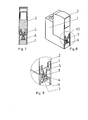
- a device combination for protection against overvoltages is shown.
- This consists of an approximately U-shaped lower part 1 and at least one plug-in with this overvoltage protection element having plug-in module 2.
- the plug-in module 2 is inserted into the corresponding recess of the lower part 1 and locked in the inserted position, between plug-in module 2 and lower part.
- 1 acting holding means or locking means are provided for example at 3.
- the corresponding locking means 3 can be unlocked or released, so that the plug-in module 2 can be removed from the lower part 1.
- a spring element 4 is arranged between the lower part 1 and plug-in module 2, which at plugged plug-in module according to FIG. 1 is biased and hidden in contours between lower part 1 and plug-in module 2 is pressed.
- the plug-in module 2 is moved counter to the insertion direction in a removal position, as shown in FIG. 2 is illustrated.
- a coil spring is arranged as a spring element 4 between the lower part 1 and plug-in module 2.
- the spring element 4 is held captive on the lower part 1.
- contacts 5 of the plug-in module 2 are contacted under spring force with contacts 6, which are part of the lower part 1.
- the spring force of the spring element 4 is dimensioned larger than the force between the contacts 5 and 6 of plug-in module 2 and lower part. 1 is generated, so that in this case the lifting of the plug-in module 2 takes place when unlocking the locking elements 3 by the force of the spring element 4.
- FIGS. 3 to 9 a device combination for protection against overvoltage with a preferably U-shaped lower part 1 and a plug-in with this, an overvoltage protection element having plug-in module 2 shown, wherein between plug-in module 2 and lower part 1 acting holding means or latching means are provided which in the inserted position of Intermesh parts and hold the parts in desired position, but which can be solved by manipulation and / or unlocked to remove the plug-in module 2 from the lower part 1 can.
- the holding means or locking means are not shown in the drawing. They are widely known in the art, so that can be dispensed with a concrete representation in the drawing.
- a spring element 4 is provided between the lower part 1 and plug-in module 2, which is biased plugged module 2 and displaced in dissolved or entrastetem holding means or locking means the plug-in module 2 opposite plugging direction in a removal position ,
- the lower part 1 can be connected in the usual way with connecting conductors, which in turn are contacted with plug contacts 6.
- the plug-in module 2 thus has corresponding plug elements 5, which are contacted with the overvoltage element of the plug-in module 2. This corresponds to the usual structure.
- the spring element 4 is formed according to the invention by at least one plug contact 6 or by a plug element 5.
- the spring element 4 is formed by the plug contact 6.
- the spring element 4 is formed by a plug contact 6, which is fork-shaped with resilient legs 7, wherein the corresponding part of the spring element 4, namely in the embodiment, the plug element 5, in the insertion direction has a wedge-like tapered contact surfaces 8, the in position according to FIGS. 6 to 8 rest on the legs 7 under resilient bias of the legs 7.
- the wedge-like contact surfaces 8 are formed on a solid metal contact element.
- the wedge-like contact surfaces 8 are formed on a bent sheet metal sheet bending contact element, which forms the male member 5.
- the invention provides a constructive solution with particularly simple means and at low cost, in which the disassembly of the plug-in module 2 from the lower part 1 is greatly facilitated for the user.
Abstract
Description
- Gerätekombination zum Schutz vor Überspannungen
- Die Erfindung betrifft eine Gerätekombination zum Schutz vor Überspannungen mit einem vorzugsweise U-förmigen Unterteil und einem mit diesem steckverbindbaren ein Überspannungsschutzelement aufweisenden Steckmodul, wobei zwischen Steckmodul und Unterteil wirkende Haltemittel oder Rastmittel vorgesehen sind, die in Stecklage der Teile ineinander greifen und die durch Manipulation lösbar und/oder entrastbar sind, um das Steckmodul zu entnehmen.
- Derartige Gerätekombinationen sind im Stand der Technik bekannt. Es wird hierzu beispielsweise auf die
DE 2006 033 274 A 1 , dieDE 10 2008 021 210 A 1 , dieDE 10 2008 017 423 A 1 verwiesen. Ähnliche Ausgestaltungen sind aus derDE 36 39 533 A 1 bekannt. - Es sind derartige Gerätekombinationen bekannt, bei denen das Steckmodul mit dem Unterteil über kraftschlüssige Elemente verbunden ist, beispielsweise durch Federdruck von Kontakten, die miteinander in der Stecklage in Verbindung stehen. Des Weiteren sind solche Gerätekombinationen bekannt, bei denen das Steckmodul mit dem Unterteil durch Rastmittel verbunden ist, die in der Stecklage der Teile ineinander greifen und die durch entsprechende Manipulationen lösbar oder entrastbar sind.
- Schließlich sind auch Gerätekombinationen bekannt, bei denen das Steckmodul mit dem Unterteil durch Formschlussmittel verbindbar ist, so dass in der Stecklage durch Formschluss eine unlösbare Verbindung erreicht wird. Durch entsprechende Manipulation kann der Formschluss aufgehoben werden, so dass dann das Steckmodul entnehmbar ist.
- Sofern bei solchen Gerätekombinationen das Steckmodul ausgewechselt werden soll oder zur Wartungszwecken entnommen werden soll, so ist eine aufwendige Manipulation erforderlich, da es relativ schwierig ist, die in der Stecklage befindlichen Teile von dem Unterteil zu lösen. Dies ist insbesondere deswegen schwierig, weil häufig mehrere Steckmodule nebeneinander angeordnet und in dem entsprechenden U-förmigen Unterteil arretiert sind.
- Ausgehend von diesem Stand der Technik liegt der Erfindung die Aufgabe zugrunde, eine Gerätekombination gattungsgemäßer Art zu schaffen, bei der die Entnahme des in Steckstellung befindlichen Steckmodules erleichtert ist und bei dem vorzugsweise keine zusätzlichen Bauteile zur erleichterten Entnahme notwendig sind.
- Zur Lösung dieser Aufgabe schlägt die Erfindung vor, dass ein zwischen Unterteil und Steckmodul wirkendes Federelement vorgesehen ist, welches bei gestecktem Steckmodul vorgespannt ist und bei gelöstem oder entrastetem Haltemittel oder Rastmittel das Steckmodul entgegen Steckrichtung in eine Entnahmeposition verstellt.
- Gemäß dieser Ausgestaltung kann das in Stecklage befindliche Steckmodul relativ einfach vom Unterteil gelöst werden, indem beispielsweise die Haltemittel oder die Rastmittel gelöst oder entrastet werden. Diese Manipulation reicht aus, um zu erreichen, dass durch das Federelement das Steckmodul zumindest teilweise aus dem Unterteil entgegen Streckrichtung herausgedrückt wird, so dass es vom Benutzer in einfacher Weise mit der Hand ergriffen und aus dem Unterteil entnommen werden kann.
- Bevorzugt kann dabei vorgesehen sein, dass zwischen Unterteil und Steckmodul mindestens eine Schraubenfeder als Federelement angeordnet ist.
- Eine solche Schraubenfeder kann relativ einfach in dem Raum zwischen Unterteil und Steckmodul angeordnet werden, wobei zudem die Federkraft der Schraubenfeder durch entsprechende Dimensionierung in einfacher Weise dem Bestimmungszweck angepasst werden kann.
- Eine alternative Lösung wird darin gesehen, dass zwischen Unterteil und Steckmodul mindestens eine Blattfeder als Federelement angeordnet ist.
- Auch eine Kombination beider Lösungen ist möglich.
- Die Anordnung einer Blattfeder als Federelement ermöglicht ebenfalls bei entsprechender Formgestaltung der Blattfeder die gewünschte Funktion, wobei auch bei einer Blattfeder die Federkraft durch entsprechende Dimensionierung und Formgebung an den Bestimmungszweck angepasst werden kann.
- Bevorzugt ist zudem vorgesehen, dass das Federelement am Unterteil unverlierbar gehalten ist.
- Bei dieser Ausgestaltung verbleibt das Federelement in jedem Falle am Unterteil, auch wenn das Steckmodul nicht gesteckt ist. Durch die unverlierbare Anordnung ist sichergestellt, dass das Federelement bei nicht gesteckten Steckmodulen nicht verloren gehen kann. Alternativ kann auch vorgesehen sein, dass das Federelement am Steckmodul unverlierbar gehalten ist.
- Auch hierbei ist eine unverlierbare Anordnung des Federelementes erreicht, wobei dieses allerdings am Steckmodul gehalten ist.
- Bevorzugt ist zudem vorgesehen, dass Kontakte des Steckmoduls unter Federkraft mit Kontakten des Unterteils verbunden sind, wenn sich das Steckmodul in gestecktem Zustand befindet, und dass die Federkraft des Federelementes größer ist als die Kontaktfederkraft zwischen den Kontakten von Steckmodul und Unterteil.
- Insbesondere bei solchen Gerätekombinationen, bei denen seitlich vom Steckmodul Kontakte abragen, die in seitliche federnde Kontakte in den Schenkeln des Unterteils kontaktiert werden und durch Federkraft gehalten werden, soll die Federkraft des Federelementes größer sein als die Haltekraft, die durch die Federkontakte zwischen Steckmodul und Unterteil wirksam werden, damit bei einer Entrastung des Steckmoduls die Federkraft des Federelementes ausreicht, um das Steckmodul in eine Auswurflage relativ zum Unterteil zu verstellen.
- Eine weitere Ausgestaltung der Erfindung sieht vor, dass das Federelement durch wenigstens einen Steckkontakt oder durch ein Steckerelement gebildet ist.
- Dadurch, dass das Federelement durch wenigstens einen Steckkontakt und/oder durch eines der Steckerelemente gebildet ist, ist es nicht erforderlich, ein zusätzliches Bauteil, also eine zusätzliche Feder einzusetzen, sondern die bisher notwendigen Bauteile zur elektrischen Kontaktierung, nämlich der Steckkontakt und/oder das Steckerelement werden als Federelement genutzt, um hierdurch nach dem Lösen der Rastmittel oder Haltemittel, das Steckmodul mindestens teilweise aus dem Unterteil entgegen Steckrichtung herauszudrücken.
- Eine bevorzugte Weiterbildung hierzu wird darin gesehen, dass das Federelement durch einen Steckkontakt oder ein Steckerelement gebildet ist, welcher oder welches gabelartig mit federnden Schenkeln ausgebildet ist, und dass das mit dem Federelement korrespondierende Teil, nämlich ein Steckerelement oder ein Steckkontakt sich in Steckrichtung keilartig verjüngend ausgebildete Kontaktflächen aufweist, die in Stecklage an den Schenkeln unter federnder Vorspannung der Schenkel anliegen.
- Die Ausbildung von federnden Steckkontakten oder federnden Steckerelementen ist zwar an sich bekannt, jedoch wird hier die entsprechende gabelartige Ausbildung des Federelementes mit federnden Schenkeln in Kombination mit dem damit zusammenwirkenden entsprechenden Teil mit keilartig verjüngend ausgebildeten Kontaktflächen genutzt, um einerseits beim Stecken einen hohen Kontaktdruck im Bereich der Kontaktierung sicherzustellen, da dann mit zunehmendem Einsteckvorgang die gabelartigen federnden Schenkel zunehmend vorgespannt werden und für einen hohen Kontaktdruck sorgen, wobei andererseits sichergestellt ist, dass bei einer Entrastung beziehungsweise beim Lösen der Haltemittel oder Rastmittel das Steckmodul aufgrund der Federkraft der federnden Schenkel aus der Stecklage heraus entgegen der Stecklage bewegt wird, um die einfache Entnahme zu ermöglichen. Der Keilwinkel der keilartigen Kontaktflächen sollte dabei deutlich größer als der Selbsthemmungswinkel sein, um den gewünschten Effekt sicherzustellen.
- Eine bevorzugte Weiterbildung hierzu wird darin gesehen, dass die keilartig ausgebildeten Kontaktflächen an einem massiven Metallkontaktelement ausgebildet sind.
- Ein solches massives Metallkontaktelement ist auch bei öfterem Gebrauch formhaltig, so dass der Keilwinkel in jedem Fall beibehalten wird, auch wenn die Elemente mehrfach voneinander gelöst und miteinander verbunden werden.
- Eine alternative bevorzugte Ausführungsform wird darin gesehen, dass die keilartig ausgebildeten Kontaktflächen an einem Blechbiegekontaktelement ausgebildet sind.
- Hierbei ist die Ausbildung des Kontaktelementes mit den keilartigen Kontaktflächen durch einen einfachen Biegevorgang zu erreichen, so dass als Ausgangsmaterial ein Blechelement genutzt werden kann, welches in entsprechende Form überführt wird.
- Alternativ kann auch vorgesehen sein, dass mindestens einer der Kontakte, nämlich Steckkontakt oder Steckerelement, federnd ausgebildet oder als gefederter Kontakt ausgebildet ist, wobei dessen Federkraft entgegen der Steckrichtung des Steckmoduls gerichtet ist.
- Bei dieser Ausbildung kann beispielsweise einer der Kontakte oder auch beide Kontakte in Steckrichtung federnd ausgebildet sein, so dass beim Stecken des Steckmodules in das Unterteil eine zunehmend höhere Federkraft notwendig ist, bis die Halteposition oder Rastposition erreicht ist. Nach Lösen des Haltemittels oder Rastmittels können die federnden Kontakte sich entspannen und damit das Steckmodul aus der Stecklage in eine Entnahmelage überführen.
- Ausführungsbeispiele der Erfindung sind in der Zeichnung dargestellt und im Folgenden näher beschrieben. Es zeigt:
- Figur 1
- eine Gerätekombination in der Normalgebrauchslage in Seitenansicht;
- Figur 2
- desgleichen in einer Demontagelage in Seitenansicht.
- Figur 3 bis 5
- eine erfindungsgemäße Gerätekombination in Teilansicht, in einer Vormontagelage;
- Figur 6 bis 8
- desgleichen in der Montagesolllage;
- Figur 9
- eine Variante in der Ansicht Gemäß
Figur 5 gesehen. - In der Zeichnungsfigur 1 und 2 ist eine Gerätekombination zum Schutz vor Überspannungen gezeigt. Diese besteht aus einem etwa U-förmigen Unterteil 1 und mindestens einem mit diesem steckverbindbaren ein Überspannungsschutzelement aufweisenden Steckmodul 2. In der Montagesolllage ist das Steckmodul 2 in die entsprechende Ausnehmung des Unterteils 1 eingesteckt und in der Stecklage verriegelt, wobei zwischen Steckmodul 2 und Unterteil 1 wirkende Haltemittel oder Rastmittel, beispielsweise bei 3 vorgesehen sind. In der Stecklage gemäß
Figur 1 greifen diese Teile ineinander und halten die Teile in der Sollposition. Durch Manipulation sind die entsprechenden Rastmittel 3 entrastbar oder lösbar, damit das Steckmodul 2 vom Unterteil 1 abgenommen werden kann. - Um diese Manipulation zu erleichtern, ist zwischen Unterteil 1 und Steckmodul 2 ein Federelement 4 angeordnet, welches bei gestecktem Steckmodul gemäß
Figur 1 vorgespannt ist und in Konturen zwischen Unterteil 1 und Steckmodul 2 verdeckt eingedrückt ist. Bei gelösten oder entrasteten Haltemitteln 3 wird das Steckmodul 2 entgegen der Steckrichtung in eine Entnahmeposition verstellt, wie dies inFigur 2 veranschaulicht ist. Im Ausführungsbeispiel ist zwischen Unterteil 1 und Steckmodul 2 eine Schraubenfeder als Federelement 4 angeordnet. Vorzugsweise ist das Federelement 4 am Unterteil 1 unverlierbar gehalten. Bei der dargestellten Ausführungsform sind Kontakte 5 des Steckmoduls 2 unter Federkraft mit Kontakten 6 kontaktiert, die Bestandteil des Unterteils 1 sind. Um auch bei dieser Ausführungsform zu erreichen, dass bei der Entrastung der Rastmittel 3 eine Verstellung des Steckmoduls 2 in die Entnahmelage erfolgt, ist die Federkraft des Federelementes 4 größer bemessen als die Kraft, die zwischen den Kontakten 5 und 6 von Steckmodul 2 und Unterteil 1 erzeugt wird, so dass auch hierbei das Anheben des Steckmoduls 2 bei Entrastung der Rastelemente 3 durch die Kraft des Federelementes 4 erfolgt. - In der Zeichnung ist in
Figur 3 bis 9 eine Gerätekombination zum Schutz vor Überspannungen mit einem vorzugsweise U-förmigen Unterteil 1 und einem mit diesem steckverbindbaren, einen Überspannungsschutzelement aufweisenden Steckmodul 2 gezeigt, wobei zwischen Steckmodul 2 und Unterteil 1 wirkende Haltemittel oder Rastmittel vorgesehen sind, die in Stecklage der Teile ineinandergreifen und die Teile in Solllage halten, die aber durch Manipulation lösbar und/oder entrastbar sind, um das Steckmodul 2 aus dem Unterteil 1 entnehmen zu können. Die Haltemittel oder Rastmittel sind in der Zeichnung nicht gezeigt. Sie sind im Stand der Technik vielfach bekannt, so dass auf eine konkrete Darstellung in der Zeichnung verzichtet werden kann. - Um ohne zusätzlichen Bauteileaufwand zu ermöglichen, dass das Steckmodul 2 aus der arretierten Stecklage gemäß
Figur 6 bis 8 freigegeben werden kann und in einfacher Weise vom Unterteil 1 abgenommen werden kann, ist zwischen Unterteil 1 und Steckmodul 2 ein Federelement 4 vorgesehen, welches bei gestecktem Steckmodul 2 vorgespannt ist und bei gelöstem oder entrastetem Haltemittel oder Rastmittel das Steckmodul 2 entgegen Steckrichtung in eine Entnahmeposition verstellt. - Das Unterteil 1 ist in üblicher Weise mit Anschlussleitern verbindbar, die wiederum mit Steckkontakten 6 kontaktiert sind. Das Steckmodul 2 weist damit korrespondierende Steckerelemente 5 auf, die mit dem Überspannungselement des Steckmoduls 2 kontaktiert sind. Dies entspricht dem üblichen Aufbau.
- Das Federelement 4 ist gemäß der Erfindung durch wenigstens einen Steckkontakt 6 oder durch ein Steckerelement 5 gebildet. Im Ausführungsbeispiel ist das Federelement 4 durch den Steckkontakt 6 gebildet.
- Des Weiteren ist im Ausführungsbeispiel das Federelement 4 durch einen Steckkontakt 6 gebildet, welcher gabelartig mit federnden Schenkeln 7 ausgebildet ist, wobei das mit dem Federelement 4 korrespondierende Teil, nämlich im Ausführungsbeispiel das Steckerelement 5, sich in Steckrichtung keilartig verjüngend ausgebildete Kontaktflächen 8 aufweist, die in Stecklage gemäß
Figur 6 bis 8 an den Schenkeln 7 unter federnder Vorspannung der Schenkel 7 anliegen. Durch diese Ausbildung wird erreicht, dass der Auswerfmechanismus nicht mit einem zusätzlichen Bauteil erreicht wird, sondern die ohnehin vorhandenen Bauteile, nämlich der Steckkontakt 6 und das Steckerelement 5 reichen aus, um die entsprechende Funktion sicherzustellen, wobei diese Elemente lediglich in ihrer Form und Wirkungsweise erfindungsgemäß ausgestaltet sind. - Bei der Ausführungsform nach
Figur 3 bis Figur 8 sind die keilartig ausgebildeten Kontaktflächen 8 an einem massiven Metallkontaktelement ausgebildet. Bei der Ausführungsform nachFigur 9 sind die keilartig ausgebildeten Kontaktflächen 8 an einem aus einem Blech gebogenen Blechbiegekontaktelement ausgebildet, welches das Steckerelement 5 bildet. - Die Erfindung stellt mit besonders einfachen Mitteln und mit geringem Kostenaufwand eine konstruktive Lösung zur Verfügung, bei der die Demontage des Steckmoduls 2 aus dem Unterteil 1 für den Benutzer erheblich erleichtert ist.
- Die Erfindung ist nicht auf das Ausführungsbeispiel beschränkt, sondern im Rahmen der Offenbarung vielfach variabel.
- Alle neuen, in der Beschreibung und/oder Zeichnung offenbarten Einzel- und Kombinationsmerkmale werden als erfindungswesentlich angesehen.
Claims (11)
- Gerätekombination zum Schutz vor Überspannungen mit einem vorzugsweise U-förmigen Unterteil (1) und einem mit diesem steckverbindbaren ein Überspannungsschutzelement aufweisenden Steckmodul (2), wobei zwischen Steckmodul (2) und Unterteil (1) wirkende Haltemittel oder Rastmittel (3) vorgesehen sind, die in Stecklage der Teile ineinander greifen und die durch Manipulation lösbar und/oder entrastbar sind, um das Steckmodul (2) zu entnehmen, dadurch gekennzeichnet, dass ein zwischen Unterteil (1) und Steckmodul (2) wirkendes Federelement (4) vorgesehen ist, welches bei gestecktem Steckmodul (2) vorgespannt ist und bei gelöstem oder entrastetem Haltemittel oder Rastmittel (3) das Steckmodul (2) entgegen Steckrichtung in eine Entnahmeposition verstellt.
- Gerätekombination nach Anspruch 1, dadurch gekennzeichnet, dass zwischen Unterteil (1) und Steckmodul (2) mindestens eine Schraubenfeder als Federelement (4) angeordnet ist.
- Gerätekombination nach Anspruch 1, dadurch gekennzeichnet, dass zwischen Unterteil (1) und Steckmodul (2) mindestens eine Blattfeder als Federelement (4) angeordnet ist.
- Gerätekombination nach einem der Ansprüche 1 bis 3, dadurch gekennzeichnet, dass das Federelement (4) am Unterteil unverlierbar gehalten ist.
- Gerätekombination nach einem der Ansprüche 1 bis 3, dadurch gekennzeichnet, dass das Federelement (4) am Steckmodul (2) unverlierbar gehalten ist.
- Gerätekombination nach einem der Ansprüche 1 bis 5, dadurch gekennzeichnet, dass Kontakte (5) des Steckmoduls (2) unter Federkraft mit Kontakten (6) des Unterteils (1) verbunden sind, wenn sich das Steckmodul (2) in gestecktem Zustand befindet, und dass die Federkraft des Federelementes (4) größer ist als die Kontaktfederkraft zwischen den Kontakten (5,6) von Steckmodul (2) und Unterteil (1).
- Gerätekombination nach einem der Ansprüche 1 bis 6, wobei das Unterteil (1) mit Anschlussleitern kontaktierte Steckkontakte (6) und das Steckmodul (2) damit korrespondierende Steckerelemente (5) aufweist, dadurch gekennzeichnet, dass das Federelement (4) durch wenigstens einen Steckkontakt (6) oder durch ein Steckerelement (5) gebildet ist.
- Gerätekombination nach Anspruch 7, dadurch gekennzeichnet, dass das Federelement (4) durch einen Steckkontakt (6) oder ein Steckerelement (5) gebildet ist, welcher oder welches gabelartig mit federnden Schenkeln (7) ausgebildet ist, und dass das mit dem Federelement (4) korrespondierende Teil, nämlich ein Steckerelement (5) oder ein Steckkontakt (6) sich in Steckrichtung keilartig verjüngend ausgebildete Kontaktflächen (8) aufweist, die in Stecklage an den Schenkeln (7) unter federnder Vorspannung der Schenkel (7) anliegen.
- Gerätekombination nach Anspruch 8, dadurch gekennzeichnet, dass die keilartig ausgebildeten Kontaktflächen (8) an einem massiven Metallkontaktelement ausgebildet sind.
- Gerätekombination nach Anspruch 8, dadurch gekennzeichnet, dass die keilartig ausgebildeten Kontaktflächen (8) an einem Blechbiegekontaktelement ausgebildet sind.
- Gerätekombination nach Anspruch 7, dadurch gekennzeichnet, dass mindestens einer der Kontakte, nämlich Steckkontakt (6) oder Steckerelement (5), federnd ausgebildet oder als gefederter Kontakt ausgebildet ist, wobei dessen Federkraft entgegen der Steckrichtung des Steckmoduls (2) gerichtet ist.
Priority Applications (1)
| Application Number | Priority Date | Filing Date | Title |
|---|---|---|---|
| SI201131197A SI2432089T1 (sl) | 2010-09-20 | 2011-08-18 | Kombinacija naprav za zaščito pred prenapetostmi |
Applications Claiming Priority (2)
| Application Number | Priority Date | Filing Date | Title |
|---|---|---|---|
| DE202010012860U DE202010012860U1 (de) | 2010-09-20 | 2010-09-20 | Gerätekombination zum Schutz vor Überspannungen |
| DE102011013300A DE102011013300B4 (de) | 2010-09-20 | 2011-03-07 | Gerätekombination zum Schutz vor Überspannungen |
Publications (3)
| Publication Number | Publication Date |
|---|---|
| EP2432089A2 true EP2432089A2 (de) | 2012-03-21 |
| EP2432089A3 EP2432089A3 (de) | 2014-11-05 |
| EP2432089B1 EP2432089B1 (de) | 2017-03-15 |
Family
ID=44532542
Family Applications (1)
| Application Number | Title | Priority Date | Filing Date |
|---|---|---|---|
| EP11006746.9A Active EP2432089B1 (de) | 2010-09-20 | 2011-08-18 | Gerätekombination zum Schutz vor Überspannungen |
Country Status (5)
| Country | Link |
|---|---|
| EP (1) | EP2432089B1 (de) |
| CN (1) | CN102544833B (de) |
| DE (1) | DE102011013300B4 (de) |
| HK (1) | HK1170854A1 (de) |
| SI (1) | SI2432089T1 (de) |
Cited By (4)
| Publication number | Priority date | Publication date | Assignee | Title |
|---|---|---|---|---|
| CN104641518A (zh) * | 2012-07-05 | 2015-05-20 | 奥宝贝特曼股份有限两合公司 | 可插接的过电压防护放电器 |
| EP2980936A1 (de) * | 2014-08-01 | 2016-02-03 | ABB France | Steckmodul einer schutzvorrichtung für elektrische anlage mit überkreuzten anschlüssen |
| WO2019091733A1 (de) * | 2017-11-07 | 2019-05-16 | Dehn + Söhne Gmbh + Co. Kg | Überspannungsschutzeinrichtung, bestehend aus einem isolierenden gehäuse zur aufnahme mindestens eines überspannungsableiters |
| WO2023165761A1 (de) * | 2022-03-02 | 2023-09-07 | Dehn Se | Teilbares überspannungsschutzgerät und steckmodul für ein teilbares überspannungsschutzgerät |
Families Citing this family (1)
| Publication number | Priority date | Publication date | Assignee | Title |
|---|---|---|---|---|
| DE102015214969A1 (de) * | 2015-08-05 | 2017-02-09 | Phoenix Contact Gmbh & Co. Kg | Überspannungsschutzgeräteensemble |
Citations (4)
| Publication number | Priority date | Publication date | Assignee | Title |
|---|---|---|---|---|
| DE3639533A1 (de) | 1986-11-20 | 1988-06-01 | Bettermann Obo Ohg | Steckbarer ueberspannungsableiter fuer elektrische anlagen |
| DE102006033274A1 (de) | 2005-02-09 | 2008-01-31 | Dehn + Söhne Gmbh + Co. Kg | Steckbare Gerätekombination zum Schutz vor Überspannungen |
| DE102008021210A1 (de) | 2008-01-30 | 2009-08-06 | Phoenix Contact Gmbh & Co. Kg | Überspannungsschutzgerät |
| DE102008017423A1 (de) | 2008-04-03 | 2009-10-15 | Phoenix Contact Gmbh & Co. Kg | Befestigungsvorrichtung zur Befestigung steckbarer elektrischer Gehäuse |
Family Cites Families (10)
| Publication number | Priority date | Publication date | Assignee | Title |
|---|---|---|---|---|
| DE1036356B (de) * | 1953-07-27 | 1958-08-14 | Siemens Ag | Schaltanlage mit ausziehbaren Geraeten oder Geraetebloecken |
| DE1912976U (de) * | 1964-11-27 | 1965-04-01 | Krone Gmbh | Halter fuer ueberspannungs-gasentladungsableiter. |
| US5273446A (en) * | 1992-11-02 | 1993-12-28 | Burndy Corporation | Zero separation force connector with wiping insertion |
| AT402991B (de) * | 1993-11-02 | 1997-10-27 | Felten & Guilleaume Ag Oester | Gerätesockel mit einsatzelement |
| DE10011385A1 (de) * | 2000-03-09 | 2001-09-13 | Abb Cmc Carl Maier Ag Schaffha | Einbaugerät für elektrische Niederspannungsinstallation |
| CN100517901C (zh) * | 2003-09-05 | 2009-07-22 | 上海电器科学研究所 | 电涌保护器可插拔模块及基座 |
| WO2006074866A1 (de) * | 2005-01-17 | 2006-07-20 | Dehn + Söhne Gmbh + Co. Kg | Steckbare gerätekombination, insbesondere zum schutz vor überspannungen |
| DE102005005914A1 (de) * | 2005-02-09 | 2006-08-10 | Dehn + Söhne Gmbh + Co. Kg | Steckbare Gerätekombination zum Schutz vor Überspannungen |
| CN101378159B (zh) * | 2007-08-27 | 2010-09-22 | 孙巍巍 | 浪涌保护器中的一种插接装置 |
| CN201315349Y (zh) * | 2008-11-07 | 2009-09-23 | 施耐德电器工业公司 | 浪涌保护器模块的连接机构 |
-
2011
- 2011-03-07 DE DE102011013300A patent/DE102011013300B4/de active Active
- 2011-08-18 EP EP11006746.9A patent/EP2432089B1/de active Active
- 2011-08-18 SI SI201131197A patent/SI2432089T1/sl unknown
- 2011-09-20 CN CN201110310116.1A patent/CN102544833B/zh active Active
-
2012
- 2012-11-12 HK HK12111423.0A patent/HK1170854A1/zh unknown
Patent Citations (4)
| Publication number | Priority date | Publication date | Assignee | Title |
|---|---|---|---|---|
| DE3639533A1 (de) | 1986-11-20 | 1988-06-01 | Bettermann Obo Ohg | Steckbarer ueberspannungsableiter fuer elektrische anlagen |
| DE102006033274A1 (de) | 2005-02-09 | 2008-01-31 | Dehn + Söhne Gmbh + Co. Kg | Steckbare Gerätekombination zum Schutz vor Überspannungen |
| DE102008021210A1 (de) | 2008-01-30 | 2009-08-06 | Phoenix Contact Gmbh & Co. Kg | Überspannungsschutzgerät |
| DE102008017423A1 (de) | 2008-04-03 | 2009-10-15 | Phoenix Contact Gmbh & Co. Kg | Befestigungsvorrichtung zur Befestigung steckbarer elektrischer Gehäuse |
Cited By (9)
| Publication number | Priority date | Publication date | Assignee | Title |
|---|---|---|---|---|
| CN104641518A (zh) * | 2012-07-05 | 2015-05-20 | 奥宝贝特曼股份有限两合公司 | 可插接的过电压防护放电器 |
| CN104641518B (zh) * | 2012-07-05 | 2016-11-02 | 奥宝贝特曼股份有限两合公司 | 可插接的过电压防护放电器 |
| EP2980936A1 (de) * | 2014-08-01 | 2016-02-03 | ABB France | Steckmodul einer schutzvorrichtung für elektrische anlage mit überkreuzten anschlüssen |
| FR3024602A1 (fr) * | 2014-08-01 | 2016-02-05 | Abb France | Cartouche de dispositif de protection d’installation electrique a connecteurs croises |
| CN105322498A (zh) * | 2014-08-01 | 2016-02-10 | Abb法国公司 | 保护设备盒以及包括基底和该保护设备盒的保护设备 |
| US9941669B2 (en) | 2014-08-01 | 2018-04-10 | Abb Schweiz Ag | Protection device cartridge of an electrical installation with intersected connectors |
| CN105322498B (zh) * | 2014-08-01 | 2019-04-26 | Abb法国公司 | 保护设备盒以及包括基底和该保护设备盒的保护设备 |
| WO2019091733A1 (de) * | 2017-11-07 | 2019-05-16 | Dehn + Söhne Gmbh + Co. Kg | Überspannungsschutzeinrichtung, bestehend aus einem isolierenden gehäuse zur aufnahme mindestens eines überspannungsableiters |
| WO2023165761A1 (de) * | 2022-03-02 | 2023-09-07 | Dehn Se | Teilbares überspannungsschutzgerät und steckmodul für ein teilbares überspannungsschutzgerät |
Also Published As
| Publication number | Publication date |
|---|---|
| HK1170854A1 (zh) | 2013-03-08 |
| SI2432089T1 (sl) | 2017-07-31 |
| EP2432089B1 (de) | 2017-03-15 |
| EP2432089A3 (de) | 2014-11-05 |
| CN102544833B (zh) | 2015-11-25 |
| DE102011013300B4 (de) | 2013-10-10 |
| DE102011013300A1 (de) | 2012-03-22 |
| CN102544833A (zh) | 2012-07-04 |
Similar Documents
| Publication | Publication Date | Title |
|---|---|---|
| DE102005037825B3 (de) | Anordnung zur axialen Sicherung eines mit einer Nut versehenen Bolzens | |
| EP3235061B1 (de) | Elektrische anschlussklemme | |
| EP2839544B1 (de) | Prüfklemmenblock | |
| EP3345253B1 (de) | Halterahmen mit rückstellkraft für steckverbindermodule | |
| EP2339701B1 (de) | Leiterplattensteckverbinder mit Verriegelungsvorrichtung | |
| EP3345257B1 (de) | Halterahmen für steckverbindermodule | |
| DE20313855U1 (de) | Anschlußvorrichtung zum Direktsteckanschluß von Leiterenden | |
| WO2017036450A1 (de) | Halterahmen für steckverbindermodule mit einem fixierbaren rastbügel | |
| EP2432089A2 (de) | Gerätekombination zum Schutz vor Überspannungen | |
| DE102017113063A1 (de) | Tragschienenbefestigung | |
| DE102014106277B4 (de) | Ein Elektronikgehäuse mit einer Anschlussleiste für ein Elektronikgerät | |
| DE202016106274U1 (de) | Eine Andockungsvorrichtung für Stromversorgungsanlagen | |
| DE102017108414A1 (de) | Schnellverschraubung, insbesondere zum Verbinden von mehrteiligen Baugruppen | |
| DE19933834A1 (de) | Steckverbinder mit Kabelzugentlastung | |
| DE102012013404A1 (de) | Steckbarer Überspannungsableiter | |
| DE202017101632U1 (de) | Steckeranordnung und Verriegelungseinrichtung zur Verriegelung eines Gegensteckverbinders an einem Steckverbinder | |
| DE202010012860U1 (de) | Gerätekombination zum Schutz vor Überspannungen | |
| DE102004002850B4 (de) | Elektrischer Steckverbinder | |
| DE2853585A1 (de) | Kupplung fuer stromschienen | |
| DE102019009196A1 (de) | Stromsammelschienensystem mit einem eine Verriegelungsanzeige aufweisenden Berührungsschutzgehäuse sowie ein entsprechendes Verfahren | |
| DE102017114958A1 (de) | Trennmechanismus für eine steckerbuchse oder einen stecker | |
| WO2017190824A1 (de) | Kupplungsvorrichtung | |
| DE102018107886B4 (de) | Steckverbindersystem mit einem bistabilen Element | |
| DE643234C (de) | Endverschluss mit Steck-Anschlussvorrichtung und Zwischenstecker | |
| DE102014116488A1 (de) | Anschlussvorrichtung für Mehrleiterkabel |
Legal Events
| Date | Code | Title | Description |
|---|---|---|---|
| PUAI | Public reference made under article 153(3) epc to a published international application that has entered the european phase |
Free format text: ORIGINAL CODE: 0009012 |
|
| AK | Designated contracting states |
Kind code of ref document: A2 Designated state(s): AL AT BE BG CH CY CZ DE DK EE ES FI FR GB GR HR HU IE IS IT LI LT LU LV MC MK MT NL NO PL PT RO RS SE SI SK SM TR |
|
| AX | Request for extension of the european patent |
Extension state: BA ME |
|
| PUAL | Search report despatched |
Free format text: ORIGINAL CODE: 0009013 |
|
| AK | Designated contracting states |
Kind code of ref document: A3 Designated state(s): AL AT BE BG CH CY CZ DE DK EE ES FI FR GB GR HR HU IE IS IT LI LT LU LV MC MK MT NL NO PL PT RO RS SE SI SK SM TR |
|
| AX | Request for extension of the european patent |
Extension state: BA ME |
|
| RIC1 | Information provided on ipc code assigned before grant |
Ipc: H01R 9/24 20060101ALI20140930BHEP Ipc: H01R 13/635 20060101ALI20140930BHEP Ipc: H01T 4/06 20060101AFI20140930BHEP |
|
| 17P | Request for examination filed |
Effective date: 20141121 |
|
| RBV | Designated contracting states (corrected) |
Designated state(s): AL AT BE BG CH CY CZ DE DK EE ES FI FR GB GR HR HU IE IS IT LI LT LU LV MC MK MT NL NO PL PT RO RS SE SI SK SM TR |
|
| GRAP | Despatch of communication of intention to grant a patent |
Free format text: ORIGINAL CODE: EPIDOSNIGR1 |
|
| RIC1 | Information provided on ipc code assigned before grant |
Ipc: H01T 4/06 20060101AFI20161116BHEP Ipc: H01R 9/24 20060101ALI20161116BHEP Ipc: H01R 13/635 20060101ALI20161116BHEP |
|
| INTG | Intention to grant announced |
Effective date: 20161201 |
|
| GRAS | Grant fee paid |
Free format text: ORIGINAL CODE: EPIDOSNIGR3 |
|
| GRAA | (expected) grant |
Free format text: ORIGINAL CODE: 0009210 |
|
| AK | Designated contracting states |
Kind code of ref document: B1 Designated state(s): AL AT BE BG CH CY CZ DE DK EE ES FI FR GB GR HR HU IE IS IT LI LT LU LV MC MK MT NL NO PL PT RO RS SE SI SK SM TR |
|
| REG | Reference to a national code |
Ref country code: CH Ref legal event code: EP Ref country code: GB Ref legal event code: FG4D Free format text: NOT ENGLISH |
|
| REG | Reference to a national code |
Ref country code: IE Ref legal event code: FG4D Free format text: LANGUAGE OF EP DOCUMENT: GERMAN |
|
| REG | Reference to a national code |
Ref country code: AT Ref legal event code: REF Ref document number: 876445 Country of ref document: AT Kind code of ref document: T Effective date: 20170415 |
|
| REG | Reference to a national code |
Ref country code: DE Ref legal event code: R096 Ref document number: 502011011822 Country of ref document: DE |
|
| REG | Reference to a national code |
Ref country code: NL Ref legal event code: MP Effective date: 20170315 |
|
| REG | Reference to a national code |
Ref country code: LT Ref legal event code: MG4D |
|
| PG25 | Lapsed in a contracting state [announced via postgrant information from national office to epo] |
Ref country code: FI Free format text: LAPSE BECAUSE OF FAILURE TO SUBMIT A TRANSLATION OF THE DESCRIPTION OR TO PAY THE FEE WITHIN THE PRESCRIBED TIME-LIMIT Effective date: 20170315 Ref country code: LT Free format text: LAPSE BECAUSE OF FAILURE TO SUBMIT A TRANSLATION OF THE DESCRIPTION OR TO PAY THE FEE WITHIN THE PRESCRIBED TIME-LIMIT Effective date: 20170315 Ref country code: GR Free format text: LAPSE BECAUSE OF FAILURE TO SUBMIT A TRANSLATION OF THE DESCRIPTION OR TO PAY THE FEE WITHIN THE PRESCRIBED TIME-LIMIT Effective date: 20170616 Ref country code: HR Free format text: LAPSE BECAUSE OF FAILURE TO SUBMIT A TRANSLATION OF THE DESCRIPTION OR TO PAY THE FEE WITHIN THE PRESCRIBED TIME-LIMIT Effective date: 20170315 Ref country code: NO Free format text: LAPSE BECAUSE OF FAILURE TO SUBMIT A TRANSLATION OF THE DESCRIPTION OR TO PAY THE FEE WITHIN THE PRESCRIBED TIME-LIMIT Effective date: 20170615 |
|
| REG | Reference to a national code |
Ref country code: FR Ref legal event code: PLFP Year of fee payment: 7 |
|
| PG25 | Lapsed in a contracting state [announced via postgrant information from national office to epo] |
Ref country code: LV Free format text: LAPSE BECAUSE OF FAILURE TO SUBMIT A TRANSLATION OF THE DESCRIPTION OR TO PAY THE FEE WITHIN THE PRESCRIBED TIME-LIMIT Effective date: 20170315 Ref country code: BG Free format text: LAPSE BECAUSE OF FAILURE TO SUBMIT A TRANSLATION OF THE DESCRIPTION OR TO PAY THE FEE WITHIN THE PRESCRIBED TIME-LIMIT Effective date: 20170615 Ref country code: SE Free format text: LAPSE BECAUSE OF FAILURE TO SUBMIT A TRANSLATION OF THE DESCRIPTION OR TO PAY THE FEE WITHIN THE PRESCRIBED TIME-LIMIT Effective date: 20170315 Ref country code: RS Free format text: LAPSE BECAUSE OF FAILURE TO SUBMIT A TRANSLATION OF THE DESCRIPTION OR TO PAY THE FEE WITHIN THE PRESCRIBED TIME-LIMIT Effective date: 20170315 |
|
| PG25 | Lapsed in a contracting state [announced via postgrant information from national office to epo] |
Ref country code: NL Free format text: LAPSE BECAUSE OF FAILURE TO SUBMIT A TRANSLATION OF THE DESCRIPTION OR TO PAY THE FEE WITHIN THE PRESCRIBED TIME-LIMIT Effective date: 20170315 |
|
| PG25 | Lapsed in a contracting state [announced via postgrant information from national office to epo] |
Ref country code: SK Free format text: LAPSE BECAUSE OF FAILURE TO SUBMIT A TRANSLATION OF THE DESCRIPTION OR TO PAY THE FEE WITHIN THE PRESCRIBED TIME-LIMIT Effective date: 20170315 Ref country code: EE Free format text: LAPSE BECAUSE OF FAILURE TO SUBMIT A TRANSLATION OF THE DESCRIPTION OR TO PAY THE FEE WITHIN THE PRESCRIBED TIME-LIMIT Effective date: 20170315 Ref country code: RO Free format text: LAPSE BECAUSE OF FAILURE TO SUBMIT A TRANSLATION OF THE DESCRIPTION OR TO PAY THE FEE WITHIN THE PRESCRIBED TIME-LIMIT Effective date: 20170315 Ref country code: ES Free format text: LAPSE BECAUSE OF FAILURE TO SUBMIT A TRANSLATION OF THE DESCRIPTION OR TO PAY THE FEE WITHIN THE PRESCRIBED TIME-LIMIT Effective date: 20170315 |
|
| PG25 | Lapsed in a contracting state [announced via postgrant information from national office to epo] |
Ref country code: SM Free format text: LAPSE BECAUSE OF FAILURE TO SUBMIT A TRANSLATION OF THE DESCRIPTION OR TO PAY THE FEE WITHIN THE PRESCRIBED TIME-LIMIT Effective date: 20170315 Ref country code: PT Free format text: LAPSE BECAUSE OF FAILURE TO SUBMIT A TRANSLATION OF THE DESCRIPTION OR TO PAY THE FEE WITHIN THE PRESCRIBED TIME-LIMIT Effective date: 20170717 Ref country code: IS Free format text: LAPSE BECAUSE OF FAILURE TO SUBMIT A TRANSLATION OF THE DESCRIPTION OR TO PAY THE FEE WITHIN THE PRESCRIBED TIME-LIMIT Effective date: 20170715 Ref country code: PL Free format text: LAPSE BECAUSE OF FAILURE TO SUBMIT A TRANSLATION OF THE DESCRIPTION OR TO PAY THE FEE WITHIN THE PRESCRIBED TIME-LIMIT Effective date: 20170315 |
|
| REG | Reference to a national code |
Ref country code: DE Ref legal event code: R097 Ref document number: 502011011822 Country of ref document: DE |
|
| PLBE | No opposition filed within time limit |
Free format text: ORIGINAL CODE: 0009261 |
|
| STAA | Information on the status of an ep patent application or granted ep patent |
Free format text: STATUS: NO OPPOSITION FILED WITHIN TIME LIMIT |
|
| PG25 | Lapsed in a contracting state [announced via postgrant information from national office to epo] |
Ref country code: DK Free format text: LAPSE BECAUSE OF FAILURE TO SUBMIT A TRANSLATION OF THE DESCRIPTION OR TO PAY THE FEE WITHIN THE PRESCRIBED TIME-LIMIT Effective date: 20170315 |
|
| 26N | No opposition filed |
Effective date: 20171218 |
|
| REG | Reference to a national code |
Ref country code: CH Ref legal event code: PL |
|
| PG25 | Lapsed in a contracting state [announced via postgrant information from national office to epo] |
Ref country code: MC Free format text: LAPSE BECAUSE OF FAILURE TO SUBMIT A TRANSLATION OF THE DESCRIPTION OR TO PAY THE FEE WITHIN THE PRESCRIBED TIME-LIMIT Effective date: 20170315 |
|
| GBPC | Gb: european patent ceased through non-payment of renewal fee |
Effective date: 20170818 |
|
| PG25 | Lapsed in a contracting state [announced via postgrant information from national office to epo] |
Ref country code: LI Free format text: LAPSE BECAUSE OF NON-PAYMENT OF DUE FEES Effective date: 20170831 Ref country code: CH Free format text: LAPSE BECAUSE OF NON-PAYMENT OF DUE FEES Effective date: 20170831 |
|
| REG | Reference to a national code |
Ref country code: IE Ref legal event code: MM4A |
|
| REG | Reference to a national code |
Ref country code: BE Ref legal event code: MM Effective date: 20170831 |
|
| PG25 | Lapsed in a contracting state [announced via postgrant information from national office to epo] |
Ref country code: LU Free format text: LAPSE BECAUSE OF NON-PAYMENT OF DUE FEES Effective date: 20170818 |
|
| PG25 | Lapsed in a contracting state [announced via postgrant information from national office to epo] |
Ref country code: GB Free format text: LAPSE BECAUSE OF NON-PAYMENT OF DUE FEES Effective date: 20170818 Ref country code: IE Free format text: LAPSE BECAUSE OF NON-PAYMENT OF DUE FEES Effective date: 20170818 |
|
| REG | Reference to a national code |
Ref country code: FR Ref legal event code: PLFP Year of fee payment: 8 |
|
| PG25 | Lapsed in a contracting state [announced via postgrant information from national office to epo] |
Ref country code: BE Free format text: LAPSE BECAUSE OF NON-PAYMENT OF DUE FEES Effective date: 20170831 |
|
| PG25 | Lapsed in a contracting state [announced via postgrant information from national office to epo] |
Ref country code: MT Free format text: LAPSE BECAUSE OF FAILURE TO SUBMIT A TRANSLATION OF THE DESCRIPTION OR TO PAY THE FEE WITHIN THE PRESCRIBED TIME-LIMIT Effective date: 20170315 |
|
| REG | Reference to a national code |
Ref country code: AT Ref legal event code: MM01 Ref document number: 876445 Country of ref document: AT Kind code of ref document: T Effective date: 20170818 |
|
| PG25 | Lapsed in a contracting state [announced via postgrant information from national office to epo] |
Ref country code: AT Free format text: LAPSE BECAUSE OF NON-PAYMENT OF DUE FEES Effective date: 20170818 |
|
| PG25 | Lapsed in a contracting state [announced via postgrant information from national office to epo] |
Ref country code: HU Free format text: LAPSE BECAUSE OF FAILURE TO SUBMIT A TRANSLATION OF THE DESCRIPTION OR TO PAY THE FEE WITHIN THE PRESCRIBED TIME-LIMIT; INVALID AB INITIO Effective date: 20110818 |
|
| PG25 | Lapsed in a contracting state [announced via postgrant information from national office to epo] |
Ref country code: CY Free format text: LAPSE BECAUSE OF NON-PAYMENT OF DUE FEES Effective date: 20170315 |
|
| PG25 | Lapsed in a contracting state [announced via postgrant information from national office to epo] |
Ref country code: MK Free format text: LAPSE BECAUSE OF FAILURE TO SUBMIT A TRANSLATION OF THE DESCRIPTION OR TO PAY THE FEE WITHIN THE PRESCRIBED TIME-LIMIT Effective date: 20170315 |
|
| PG25 | Lapsed in a contracting state [announced via postgrant information from national office to epo] |
Ref country code: TR Free format text: LAPSE BECAUSE OF FAILURE TO SUBMIT A TRANSLATION OF THE DESCRIPTION OR TO PAY THE FEE WITHIN THE PRESCRIBED TIME-LIMIT Effective date: 20170315 |
|
| PG25 | Lapsed in a contracting state [announced via postgrant information from national office to epo] |
Ref country code: AL Free format text: LAPSE BECAUSE OF FAILURE TO SUBMIT A TRANSLATION OF THE DESCRIPTION OR TO PAY THE FEE WITHIN THE PRESCRIBED TIME-LIMIT Effective date: 20170315 |
|
| P01 | Opt-out of the competence of the unified patent court (upc) registered |
Effective date: 20230509 |
|
| PGFP | Annual fee paid to national office [announced via postgrant information from national office to epo] |
Ref country code: IT Payment date: 20230831 Year of fee payment: 13 Ref country code: CZ Payment date: 20230815 Year of fee payment: 13 |
|
| PGFP | Annual fee paid to national office [announced via postgrant information from national office to epo] |
Ref country code: SI Payment date: 20230809 Year of fee payment: 13 Ref country code: FR Payment date: 20230821 Year of fee payment: 13 |
|
| PGFP | Annual fee paid to national office [announced via postgrant information from national office to epo] |
Ref country code: DE Payment date: 20231030 Year of fee payment: 13 |