EP2431322B1 - Kran mit verstifteten Verbindungssystem für Kransäulensegmente - Google Patents
Kran mit verstifteten Verbindungssystem für Kransäulensegmente Download PDFInfo
- Publication number
- EP2431322B1 EP2431322B1 EP11181910.8A EP11181910A EP2431322B1 EP 2431322 B1 EP2431322 B1 EP 2431322B1 EP 11181910 A EP11181910 A EP 11181910A EP 2431322 B1 EP2431322 B1 EP 2431322B1
- Authority
- EP
- European Patent Office
- Prior art keywords
- connectors
- pin
- extensions
- connector
- holes
- Prior art date
- Legal status (The legal status is an assumption and is not a legal conclusion. Google has not performed a legal analysis and makes no representation as to the accuracy of the status listed.)
- Active
Links
Images


Classifications
-
- B—PERFORMING OPERATIONS; TRANSPORTING
- B66—HOISTING; LIFTING; HAULING
- B66C—CRANES; LOAD-ENGAGING ELEMENTS OR DEVICES FOR CRANES, CAPSTANS, WINCHES, OR TACKLES
- B66C23/00—Cranes comprising essentially a beam, boom, or triangular structure acting as a cantilever and mounted for translatory of swinging movements in vertical or horizontal planes or a combination of such movements, e.g. jib-cranes, derricks, tower cranes
- B66C23/62—Constructional features or details
- B66C23/72—Counterweights or supports for balancing lifting couples
- B66C23/74—Counterweights or supports for balancing lifting couples separate from jib
- B66C23/76—Counterweights or supports for balancing lifting couples separate from jib and movable to take account of variations of load or of variations of length of jib
-
- B—PERFORMING OPERATIONS; TRANSPORTING
- B66—HOISTING; LIFTING; HAULING
- B66C—CRANES; LOAD-ENGAGING ELEMENTS OR DEVICES FOR CRANES, CAPSTANS, WINCHES, OR TACKLES
- B66C23/00—Cranes comprising essentially a beam, boom, or triangular structure acting as a cantilever and mounted for translatory of swinging movements in vertical or horizontal planes or a combination of such movements, e.g. jib-cranes, derricks, tower cranes
- B66C23/62—Constructional features or details
- B66C23/64—Jibs
- B66C23/70—Jibs constructed of sections adapted to be assembled to form jibs or various lengths
-
- Y—GENERAL TAGGING OF NEW TECHNOLOGICAL DEVELOPMENTS; GENERAL TAGGING OF CROSS-SECTIONAL TECHNOLOGIES SPANNING OVER SEVERAL SECTIONS OF THE IPC; TECHNICAL SUBJECTS COVERED BY FORMER USPC CROSS-REFERENCE ART COLLECTIONS [XRACs] AND DIGESTS
- Y10—TECHNICAL SUBJECTS COVERED BY FORMER USPC
- Y10T—TECHNICAL SUBJECTS COVERED BY FORMER US CLASSIFICATION
- Y10T29/00—Metal working
- Y10T29/49—Method of mechanical manufacture
- Y10T29/49826—Assembling or joining
- Y10T29/49947—Assembling or joining by applying separate fastener
- Y10T29/49959—Nonresilient fastener
-
- Y—GENERAL TAGGING OF NEW TECHNOLOGICAL DEVELOPMENTS; GENERAL TAGGING OF CROSS-SECTIONAL TECHNOLOGIES SPANNING OVER SEVERAL SECTIONS OF THE IPC; TECHNICAL SUBJECTS COVERED BY FORMER USPC CROSS-REFERENCE ART COLLECTIONS [XRACs] AND DIGESTS
- Y10—TECHNICAL SUBJECTS COVERED BY FORMER USPC
- Y10T—TECHNICAL SUBJECTS COVERED BY FORMER US CLASSIFICATION
- Y10T403/00—Joints and connections
- Y10T403/55—Member ends joined by inserted section
- Y10T403/553—Laterally inserted section
Definitions
- the present invention relates to a crane according to the preamble of claim 1.
- Each of the sectional column members is made of a plurality of chords and lacing or lattice elements.
- the terminal end portions of each chord are generally provided with connectors of one form or another to secure abutting column segments together and to carry compressive loads between abutting chords.
- Typical connectors comprise male and female lugs secured by a pin carrying compressive loads in double shear.
- An example 67 m (220 foot) boom may be made of a 12 m (40 foot) boom butt pivotally mounted to the crane upper works, a 9 m (30 foot) boom top equipped with sheaves and rigging for lifting and supporting loads, with five sectional boom members in between: one 3 m (10 feet) in length, one 6 m (20 feet) in length and three 12 m (40 feet) in length.
- Such an example boom has six boom segment connections. Typically each segment has four chords, and hence four connectors, making a total of 24 connectors that must be aligned and pinned to assemble the boom.
- a 12 m (40 foot) long sectional boom member may weigh over 22680 kg (50,000 lbs).
- an assist crane is required to lift the boom member.
- One rigger usually then holds the suspended boom segment in general alignment while a second rigger uses a large hammer (4,5 kg or 6,8 kg (10 or 15 Ibs.)) to manually drive the pin, which typically has a long taper, into position.
- the pins connecting the boom segments are generally used to carry the compressive loads between chords.
- the pins have a tight fit, further increasing the difficulty in assembling the boom.
- it may take three men (a crane operator and two riggers) four or more hours to assemble the example 67 m (220 foot) boom. Where the crane is moved frequently, the costs to assemble and disassemble the boom may exceed the cost to lift and position the load for which the crane is used.
- EP 2065332 A2 discloses a crane with a mated connection between two sectional column members according to the preamble of independent claim 1.
- boom segments have connectors that include at least one tight fitting pin that can be initially used to hold the boom segments together while other pins, which may have a looser fit, are then inserted to finish the connection.
- each connector includes two pins, thus reducing the size of each pin.
- alignment surfaces and/or stop surfaces on the preferred connectors allow the connectors to be easily aligned for insertion of the pins, and allow the boom segments to be initially connected and then rotated into a final position where the remainder of the connections between segments can be made.
- the invention is a crane having an upper works rotatably mounted on a lower works, the crane including at least one column member, the column member comprising: at least a first and a second column segment each with a longitudinal axis and a first and a second end, the second end of the first segment being coupled to the first end of the second segment; at least a first, a third and a fifth connector on the second end of the first segment respectively mating with at least a second, a fourth and a sixth connector on the first end of the second segment; each of the connectors comprising at least a first extension having a through-hole there through, the through-hole having an axis perpendicular to said longitudinal axis and positioned in the extension such that the through-holes of mating connectors are aligned when the column segments are aligned; each of the connectors comprising a compressive load bearing surface, the compressive load bearing surfaces being positioned to carry compressive loads between the first and second column segments when the column segments are aligned;
- the invention is a mated connection between two sectional column members comprising: a first connecter affixed to an end of a first sectional column member and a second connector affixed to an end of a second sectional column member; each first and second connector having a first and second set of extensions, with each extension having a through-hole there through sized to receive a pin; each connector also comprising a compressive load bearing surface positioned between the first set and second set of extensions, the compressive load bearing surface of the first connector being in face-to-face relationship with the compressive load bearing surface of the second connector; and a first pin passing through the through-holes of the first set of extensions of the first connector and the first set of extensions of the second connector in a tight fitting manner, and a second pin passing through the through-holes of the second set of extensions of the first connector and the second set of extensions of the second connector in a loose fitting manner.
- the invention is a method of connecting first and second segments of a lift crane column, the column segments each comprising a longitudinal axis and at least three chords, with each of the chords having a connector on each end thereof, the method comprising: a) bringing the two column segments together such that at least one extension having a through-hole there through on at least a first connector on the first column segment is interleaved respectively with at least two extensions having a through-hole there through on at least a second respective connector on the second column segment to form at least a first pair of mated connectors, with the through-holes in the connector extensions being generally aligned; b) fastening the mated first and second connectors together with a pin that fits tightly in the through-holes of the extensions, providing a pivoting connection; and c) pinning the previously non-coupled connectors to their respective mating connector with a loose fitting pin.
- large sections of a lift crane boom or other crane column members can be assembled with a faster set-up time.
- One of the pins can be tight fitting, which may need to be put in place with a hydraulic cylinder, but other pins can be more loosely fit, allowing them to be inserted more quickly, and without the need of a hydraulic cylinder.
- a second set of riggers can insert the other pins while riggers with a hydraulic pin pusher move to the next segment connection.
- the segments need to be connected from a non-aligned positioned, once the more tightly fitting pin or pins are in place, the sections can be pivoted into and will automatically stop in an aligned configuration with the through-holes on the remaining connectors already lined up.
- smaller diameter pins are used, with two pins on each connection.
- the use of the invention means that only the top pin or pins on each upper chord are tight fitting, while the remaining pins are more loosely fit.
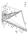
- Fig. 1 is a side elevational view of a crane with a sectional boom utilizing the pinned column segment connection system of the present invention.
- Fig. 2 is a side elevational view of two boom segments being brought together from a first position to form the boom on the crane of Fig. 1 .
- Fig. 3 is a side elevational view of the two boom segments of Fig. 2 being brought together from a second position to form the boom on the crane of Fig. 1 .
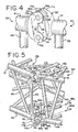
- Fig. 4 is a perspective view of a mated pair of connectors used to connect the boom segments of Fig. 2 .
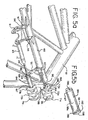
- Fig. 5 is a perspective view of the ends of two boom segments of Fig. 2 being assembled.
- Fig. 5a is a top perspective view of one corner of a boom segment with a pin insertion and retraction device attached.
- Fig. 5b is a perspective view of a pin used in the connection system of the present invention.
- Fig. 6 is a top plan view of one of the boom segments of Fig. 2 .
- Fig. 7 is a side elevational view of one of the boom segments of Fig. 2 .
- Fig. 8 is an enlarged top plan view of a female connector used on the boom segment of Fig. 6 .
- Fig. 9 is an enlarged top plan view of a male connector used on the boom segment of Fig. 6 .
- Fig. 10 is an enlarged side elevational view of the female connector of Fig. 8 .
- Fig. 11 is an enlarged side elevational view of the male connector of Fig. 9 .
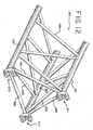
- Fig. 12 is a partial perspective view of an alternate boom section utilizing the present invention.
- the preferred embodiment of the present invention relates to a high capacity mobile lift crane, other aspects of which are disclosed in U.S. Patent No. 7,546,928 (Mobile Lift Crane With Variable Position Counterweight), U.S. Patent No. 7,762,412 (Mast Raising Structure And Process For High-Capacity Mobile Lift Crane), U.S. Patent No. 7,946,560 (Crane Hook Block), U.S. Patent No. 7,954,657 (Connection System For Crane Boom Segments), U.S. Patent No. 7,967,158 (Mobile Lift Crane With Variable Position Counterweight) and U.S. Patent No. 7,997,432 (Trunnion Transportation System And Crane Using Same).
- top For ease of reference, designation of “top,” “bottom,” “horizontal” and “vertical” are used herein and in the claims to refer to portions of a sectional boom in a position in which it would typically be assembled on or near the surface of the ground. These designations still apply although the boom may be raised to different angles, including a vertical position.
- the diameters referred to are the diameters of the operational sections of the pins, excluding any tapered section. Parts being designated as the same size means that they are the same size within normal tolerances for crane parts of their nature.
- "Tight fitting” and "loose fitting” are relative terms, meaning the tightness of one pin in the hole it is designated for compared to the tightness of fit of another pin in its hole.
- the desirable tightness of the fit of the top pins and the desired looseness of the bottom pins is dependent on the column segment configurations.
- the top pins will have a significantly different tightness of fit than the bottom pins. Examples below provide meaningful understanding of the terms “tight” and "loose”.
- the mobile lift crane 10, as shown in Fig. 1 includes lower works, also referred to as a carbody 12, and moveable ground engaging members in the form of crawlers 14 and 16.
- crawlers 14 and 16 there are of course two front crawlers 14 and two rear crawlers 16, only one each of which can be seen from the side view of Fig. 1 .
- the ground engaging members could be just one set of crawlers, one crawler on each side. Of course additional crawlers than those shown, or other ground engaging members such as tires, can be used.
- a rotating bed 20 is rotatably connected to the carbody 12 using a roller path, such that the rotating bed 20 can swing about an axis with respect to the ground engaging members 14, 16.
- the rotating bed supports a boom 50 pivotally mounted on a front portion of the rotating bed; a mast 28 mounted at its first end on the rotating bed; a backhitch 30 connected between the mast and a rear portion of the rotating bed; and a moveable counterweight unit 13 having counterweights 34 on a support member 33.
- the counterweights may be in the form of multiple stacks of individual counterweight members on the support member 33.
- Boom hoist rigging 25 between the top of mast 28 and boom 50 is used to control the boom angle and transfers load so that the counterweight can be used to balance a load lifted by the crane.
- a hoist line 24 extends from the boom 50, supporting a hook 26.
- the rotating bed 20 may also includes other elements commonly found on a mobile lift crane, such as an operator's cab and hoist drums for the rigging 25 and hoist line 24.
- the boom 50 may comprise a luffing jib pivotally mounted to the top of the main boom, or other boom configurations.
- the backhitch 30 is connected adjacent the top of the mast 28.
- the backhitch 30 may comprise a lattice member designed to carry both compression and tension loads as shown in Fig. 1 .
- the mast is held at a fixed angle with respect to the rotating bed during crane operations, such as a pick, move and set operation.
- the counterweight unit is moveable with respect to the rest of the rotating bed 20.
- the counterweight unit 13 is designed to be moved in and out with respect to the front of the crane in accordance with the invention disclosed in U.S. Patent No. 7,546,928 (Mobile Lift Crane With Variable Position Counterweight) and U.S. Patent No. 7,967,158 (Mobile Lift Crane With Variable Position Counterweight).
- a tension member 32 connected adjacent the top of the mast supports the counterweight unit.
- a counterweight movement structure is connected between the rotating bed and the counterweight unit such that the counterweight unit may be moved to and held at a first position in front of the top of the mast, shown in solid lines in Fig. 1 , and moved to and held at a second position rearward of the top of the mast, shown in dotted lines in Fig. 1 .
- a hydraulic cylinder 36, pivot frame 40 and a rear arm 38 may be used to move the counterweight unit.
- the rear arm 38 actually has both left and right members, only one of which can be seen in Fig. 1
- the pivot frame has two side members, and the hydraulic cylinder comprises two cylinders that move in tandem.
- one larger hydraulic cylinder, or a rack and pinion structure, powered by preferably four hydraulic motors, could be used in place of the two hydraulic cylinders 36 to provide the linear actuation.
- the pivot frame could be made as a solid plate structure, and the two rear arms 38 could be replaced by one single structure.
- the pivot frame 40 is connected between the rotating bed 20 and hydraulic cylinder 36, and the rear arm 38 is connected between the pivot frame 40 and the counterweight unit.
- the hydraulic cylinder 36 is pivotally connected to the rotating bed 20 on a support frame which elevates the hydraulic cylinder 36 to a point so that the geometry of the cylinder 36, pivot frame 40 and rear arm 38 can move the counterweight through its entire range of motion. In this manner the cylinder 36 causes the rear arm 38 to move the counterweight unit when the cylinder is retracted and extended.
- Arms 38 have an angled portion 39 at the end that connects to the pivot frame 40. This allows the arms 38 to connect directly in line with the side members of pivot frame 40. The angled portion 39 prevents the arms 38 from interfering with the side members of the pivot frame the when the counterweight is in the position shown in solid lines in Fig. 1 .
- the boom 50 is made of several sectional members, including a boom butt 51, boom insert segments 52, 53, 54 and 55, which may vary in number and be of different lengths, and a boom top 56.
- the sectional boom members 51-56 typically are comprised of multiple chords.
- Each boom segment 53 and 54 has a rectangular cross section with a chord at each corner.
- the segments 53 and 54 which are representative and may be considered as first and second boom segments, each have a longitudinal axis 41 ( Fig. 2 ), as well as first and second ends.
- the second end of the first segment 53 is coupled to the first end of the second segment 54.
- the chord members are made of steel with a circular, tubular cross section.
- a horizontal plane containing the longitudinal axis 41 can be considered to divide the boom segment into first and second longitudinal portions 67 and 68, with the two top chords 61 being present in the first portion 67 and the two bottom chords 63 being present in the second longitudinal portion of the boom segment 68.
- first and second longitudinal portions are identified for ease in explaining the invention.
- other configurations of boom segments are possible with a differing number of chords, and different ways of designating longitudinal portions of the boom segments are possible.
- Each chord member has a vertical neutral axis and a horizontal neutral axis. Compressive loads applied at the intersection of the vertical and horizontal neutral axes of a chord, or symmetrically about the horizontal and vertical neutral axes, will not induce bending moments within the chord.
- connectors that are used to connect boom segments together are mounted on the boom segments at the ends of the chords such that compressive loads transmitted through the connectors are symmetrical about the neutral axes of the chords.
- either the connectors on the top chords 61 can be connected first, or, as shown in Fig. 3 , the connectors on the bottom chords 63 can be connected first, while the boom segments are in a non-aligned configuration.
- the boom segments can then be pivoted and will automatically stop in a position where the additional connectors are aligned. It is also possible that the boom segments can be brought together with the longitudinal axes of the segments already lined up.
- the configuration of the connectors facilitates such an alignment and coupling of the boom segments, also as explained in more detail below.
- the connectors of the first embodiment are of two types, which may be referred to as first and second connectors, shown in detail in Figs. 8-11 .
- Each connector includes at least one extension having an aperture in the form of a through-hole there through sized to receive a pin, the extensions extending away from the boom segments to which they are attached, and the aperture having an axis perpendicular to that longitudinal axis.
- the extensions and apertures are positioned on their respective connectors such that when the second end of the boom segment is in an aligned position with and coupled to the first end of an identical boom segment, with connectors on the two boom segments coupled together, the extensions of the coupled connectors overlap one another and the apertures are aligned such that the pin may be inserted through the apertures to secure the connector of the second end of the boom segment to the connector of the first end of an identical boom segment.
- Inventive boom segments used in the boom may differ in a number of respects, particularly in regard to features that have to do with crane assembly and operation other than the segment-to-segment connection system.)
- Preferably half of the connectors have a first number of extensions and half of the connectors have a second number of extensions, the second number being one greater than the first number, the connector on opposite ends of each chord having a different number of extensions from each other.
- the connector on the first end of the chord of the first longitudinal portion of the boom segment includes a first alignment surface and a stop surface.
- the connector on the second end of the chord of the first longitudinal portion of the boom segment includes a second alignment surface and a stop surface. In this embodiment, these surfaces are provided by different structures on the connectors.
- the first and second alignment surfaces cooperate such that when the first and second connectors are being brought together during boom assembly, the alignment surfaces urge the boom segments into a relative position such that the apertures through the extensions in the connectors are aligned sufficiently such that a tapered pin can be inserted through the apertures of the extensions in the first and second mating connectors even if the boom segments are not axially aligned.
- the placement of the stop surface on the connectors are such that, when an identical boom segment is positioned such that a pin can be inserted through the apertures in the extensions of the connectors of the remainder of the chords on the second longitudinal portion of the boom segments, the stop surfaces cooperate to align the apertures in the extensions of their respective connectors when the stop surfaces contact one another.
- Fig. 4 shows a mated connection between two sectional boom members 53 and 54.
- a first connecter 70 is affixed to the second end of a top chord 61 on a first sectional boom member 53.
- the connector 70 has two sets of three extensions 71a, 72a, and 73a, and 71b, 72b and 73b (best shown in Fig. 5 ), each having an aperture there through in the form of a through-hole.
- the connector 70 also includes a first alignment surface in the form of rounded outer surfaces 74 on the distal ends of each extension.
- the connector 70 further comprises a generally flat, compressive load bearing surface 78 that extends across the width of the connector and separates the two sets of extensions. In this embodiment, the load bearing surface 78 provides the stop surface for the connector.
- the second connector 80 is affixed to the first end of a top chord 61 on a second sectional boom member 54.
- the second connector 80 has two sets of two extensions 81a and 82a, and 8 1 b and 82b, each having an aperture there through in the form of a through-hole.
- the extensions 71, 72 and 73 of each set on connector 70 are interleaved with the respective set of extensions 81 and 82 on connector 80 when the connectors are coupled together, as seen in Fig. 4 .
- the connector 80 has second alignment surfaces in the form of pockets 84 adjacent the base of the outside portions of the extensions 81 and 82 matching the shape of the rounded outer surfaces 74. Drain holes 89 are provided in each connector 70, 80, as shown in Figs. 10 and 11 .
- the connector 80 also includes a generally flat, compressive load bearing surface 88 extending across the width of the connector. In this embodiment, the load bearing surfaces 78 and 88 provide the stop surfaces for the connector.
- the second alignment surfaces 84 and rounded first alignment surfaces 74 are in close proximity but not quite in contact with one another when the boom segments are in axial alignment, as shown in Fig. 4 .
- the connectors 70 and 80 can still be coupled to one another. In that instance, the first alignment surfaces 74 and second alignment surfaces 84 will contact one another as the boom sections are brought close to one another.
- the apertures in the extensions 71, 72, 73, 81 and 82 are in close enough alignment that a tapered pin (shown in Fig. 5b ) may be inserted through the apertures, meaning that it can start to be inserted, and the taper on the pin will cause the apertures to fully align as the pin is driven through the apertures.
- a tapered pin shown in Fig. 5b
- the compressive load bearing surface 78 will contact the compressive load bearing surface 88 to stop the pivoting at the point where the boom segments are aligned.
- the stop surfaces are positioned such that if one set of first and second connectors are coupled together by a pin through their apertures and the boom segments are in a non-aligned position, rotation of the boom segments about the pin through the apertures of the coupled connectors to the point where the stop surfaces of the additional connectors on the boom segments contact one another will bring the boom segments into alignment and the apertures on those additional connectors into alignment.
- another pin may be placed through the second set of extensions 7 1 b, 72b, 73b, 8 1 b and 82b.
- the bottom chords 63 are provided with connectors that have the same configuration as the connectors 70 and 80 on the top chords 61.
- the compressive load bearing surfaces of these lower connectors will come into contact with one another at the same time the compressive load bearing surfaces 78 and 88 on the top connectors come into contact with one another.
- the lower compressive load bearing surfaces thus also act as stop surfaces, aligning the apertures in the lower connectors.
- the connectors of the present invention allow sectional boom members to be connected and then rotate through a full 90° angle. Even if the boom segments are at an angle of 90° from their aligned position, first alignment surfaces 74 and second alignment surfaces 84 can be brought into contact with one another, making the apertures through the extensions close enough in alignment that a pin may be inserted. Of course after the pin is fully inserted, second alignment surfaces 84 and surfaces 74 do not contact each other. This assures that all loads are carried through the surface to surface contact of the compressive load bearing surfaces 78 and 88. Any tension loads can be carried by the pins.
- the compressive load bearing surfaces are preferably symmetrical about the horizontal and vertical neutral axes of the chord to which they are attached.
- the boom segments When the boom segments are assembled from a non-aligned arrangement as shown in either of Figs. 2 or 3 , the following steps will normally occur.
- the two boom segments will be brought together such that two connectors 70 on the first boom segment 53 mate with two respective connectors 80 on the second boom segment 54 to form two pairs of mated connectors, but the longitudinal axes 41 of the two segments are not aligned.
- the remaining connectors on each segment are not coupled.
- the mated connectors are fastened together with a pivoting connection as pins are inserted though the apertures on one side of both pairs of mated connectors.
- the two segments 53 and 54 are then pivoted with respect to each other about the pivoting connection until the compressive load bearing surface 78 contacts the compressive load bearing surface 88.
- This arrangement allows the boom sections to "back bend” about either the top or bottom boom connection.
- the boom sections can be rotatably engaged with either the top or bottom pins inserted, then pivoted to a position where the segments are aligned and the opposite connectors can be pinned and the other pin inserted through the apertures on the inside of the top connectors.
- the boom segments may also be brought together in a generally aligned position, where the connectors on the top and bottom chords contact each other at roughly the same time. It will be appreciated that with the preferred geometry of the connectors, if the boom sections are not exactly aligned as they come together, the first alignment surfaces 74 will engage the second alignment surfaces 84 and guide the connectors to slide relative to one another until the alignment surfaces 74 are fully seated in pockets 84, thus guiding the boom segments into the proper alignment such that when the engagement member and second alignment surface on both the upper and lower sets of connectors are fully engaged, the apertures through the extensions in the connectors are aligned such that a pin can be inserted through the apertures of all extensions in the first and second mating connectors.
- the boom segments preferably include brackets so that hydraulic pin insertion equipment can be mounted on the boom segment in a position to force the pin through the apertures.
- Fig. 5a shows one such configuration for a hydraulic pin inserter.
- Brackets 92 support the extensions 96 of pins 95 that are sized to fit in the apertures in the extensions 71, 72, 73, 81 and 82.
- Another bracket 91 is connected to the center of the top lacing element 65 that spans between the ends of top chords 61.
- a hydraulic pin insertion/retraction tool 93 with a double acting hydraulic cylinder can fit into one side of bracket 91 and connect to the extension 96 of the pin 95.
- pin 94 is removed, allowing bracket 91 to pivot about pin 97 into an upper position. Pin 94 is then inserted through-holes 98 and the tool 93 can be put back into the bracket 91 and connected to the extension 96 of the upper pin 95. Retraction of the pins is carried out in a reverse operation.
- the hydraulic pin insertion/retraction tool 93 may only need to be used to insert one of the pins 95, and the other pin can be inserted by hand.
- Pin 95a is shown in Fig. 5b . It has a head 192, a main body 194, and a taper 196.
- a counter bore 198 is made in the head 192 to provide a place for the connection of extension 96.
- the counter bore 198 has a threaded hole 191 in its bottom, which may be used to hold the pin for plating during the manufacturing process.
- a hole 199 passing all of the way through head 192 intersects the counter bore 198.
- a hole (not shown) is provided on the end of extension 96 that will match up with hole 199 so that a retaining pin can pass through hole 199 to connect extension 96 to pin 95a when the pin is being inserted or withdrawn from connector 70.
- Another hole 197 all the way through the body 194 of the pin 95a allows a retaining pin to be inserted to hold the pin 95a in place after it passes through the extensions of the connectors.
- the other pins 95b, 95c and 95d are formed the same way, but have a smaller diameter body.
- the pin 95a is sized to fit tightly in the through-holes of the extensions 71a, 81a, 72a, 82a and 73a. While the degree of difference between the diameter of the body 194 and the diameter of the through-holes in the extensions on the connectors may vary with different sizes of column segments, in the exemplary embodiment the pin 95a has a diameter of 110.20mm, with a tolerance of +0.00mm, -0.08 mm, while the holes have an internal diameter of 110.40mm, with a tolerance of +0.08mm, -0.00mm. The smallest possible difference between the pin diameter and the hole diameter (minimum clearance) is thus 0.20mm.
- the ratio of a) the difference between the inside diameter of the through-holes and the outside diameter of the tight pin to b) the outside diameter of the tight pin is less than 0.0055, preferably less than 0.004, more preferably less than 0.0035, and even more preferably less than 0.002.
- the ratio X is 0.0018 when the pin is as large as it can be and still be within its tolerance and the hole is as small as it can be and still be within its tolerance.
- the ratio X under minimum material conditions is 0.0033.
- the loose fitting pins 95b, 95c and 95d have a main body diameter of 109.65mm, with a tolerance of +0.00mm, -0.08 mm, while the size of the holes is the same.
- the ratio of a) the difference between the inside diameter of the through-holes and the outside diameter of the loose fitting pins to b) the outside diameter of the loose fitting pins (referred to as Y) is greater than 0.0065, preferably greater than 0.007 and more preferably greater than 0.0075.
- the ratio Y is 0.0068 at the minimum clearance conditions, and 0.0083 at the extreme ends of the tolerance.
- the difference between ratios X and Y will be at least 0.003.
- M equals the difference between the inside diameter of the through-holes of the first and second connectors and the outside diameter of the tightly fitting pin.
- N equals the difference between the inside diameter of the through-holes of the third and fourth connectors and the outside diameter of the loose fitting pin.
- M is preferably less than 0.5mm, and more preferably less than 0.4mm, and N is preferably greater than 0.6mm and more preferably greater than0.7mm for large booms where the present invention is particularly useful.
- the pins 95b, 95c and 95d and their respective holes preferably have a clearance N that is at least twice, and more preferably three times, the clearance M between pin 95a and the holes through which it fits.
- a clearance N that is at least twice, and more preferably three times, the clearance M between pin 95a and the holes through which it fits.
- each of the column segments is made from three chords and interlacing elements, and only three connectors are used to hold the first and second column segments together.
- One end of one of the segments 250 of this embodiment is shown in Figure 12 .
- the segment 250 includes three chords 261, 262 and 263 held together by lacing elements 265.
- connectors 271, 272 and 273 with two sets of three extensions each are positioned on the ends of the chords on one end of the column segment 250, while connectors just like connectors 80 having two sets of two extensions each can be on the opposite end (not shown) of the column segment 250.
- the pins used to hold the connectors 271, 272 and 273 to their mating connectors include both tight and loose fitting pins.
- one tight fitting pin can be used in the holes in the top set of extensions in connector 271 while loose fitting pins can be used in the holes in the bottom set of extensions on connector 271 and each of the sets of extensions in connectors 272 and 273.
- two tight pins could be used in the bottom holes of connectors 272 and 273, and loose pins can be used in the top holes of connectors 272 and 273 and in both sets of holes in connector 271.
- One of the benefits of either embodiment is that common castings can be used to make all connectors on the same end of the boom segment, which simplifies manufacturing.
- the castings are pre-machined and then welded to the chord members.
- the chord members are then assembled into a boom segment, and then final machining on the connectors is performed, including drilling the final bore, which is preferably the same size for all through-holes in all extensions on all connectors on the boom segment. This procedure allows the final configuration of the connectors to be made without having to worry about distortion due to welding and machining of the large boom sections.
- Another advantage of the present invention is particularly useful for very high capacity booms. While the connectors are primarily designed for large compressive loads, there may be times when the connectors need to be able to handle tension loads across the connections. The pins through the apertures are able to handle these tension loads.
- the apparatus of the present invention is capable of being incorporated in the form of a variety of embodiments, only a few of which have been illustrated and described above.
- the pins could all be the same size, with the holes into which the tight pins are inserted being smaller than the holes into which the loose fitting pins are inserted.
- the invention could be used on column segments where each connector was held together with only one pin through one set of extensions.
- connectors with fewer or more extensions could be used, though it is preferable that one of the connectors have one more extensions than the number of extensions on the mating connector. While the invention has been described as it is used on a lift crane, it could be used on column segments on other types of cranes, such as tower cranes. The described embodiments are to be considered in all respects only as illustrative and not restrictive, and the scope of the invention is therefore indicated by the appended claims rather than by the foregoing description. All changes which come within the meaning and range of equivalency of the claims are to be embraced within their scope.
Landscapes
- Engineering & Computer Science (AREA)
- Mechanical Engineering (AREA)
- Jib Cranes (AREA)
Claims (18)
- Kran mit einem auf einem Unterwagen (12) drehbar gelagerten Oberwagen, wobei der Kran (10) zumindest ein Säulenteil (50) aufweist, wobei das Säulenteil (50) umfasst:a) zumindest ein erstes und ein zweites Säulensegment (53, 54) mit jeweils einer Längsachse und einem ersten und einem zweiten Ende, wobei das zweite Ende des ersten Segments (53) an das erste Ende des zweiten Segments (54) gekoppelt ist;b) zumindest ein erstes, ein drittes und ein fünftes Verbindungsteil (70) am zweiten Ende des ersten Segments (53), die jeweils mit einem zweiten, einem vierten und einem sechsten Verbindungsteil (80) am ersten Ende des zweiten Segments (54) zusammenpassen;c) wobei jedes der Verbindungsteile (70, 80) zumindest eine erste Verlängerung (71a, 81a) mit einem durchgehenden Druchgangsloch umfasst, wobei das Durchgangsloch eine Achse senkrecht zur Längsachse aufweist und in den Verlängerungen (71a, 81a) angeordnet ist, so dass die Durchgangslöcher zusammenpassender Verbindungsteile (70, 80) fluchten, wenn die Säulensegmente (53, 54) ausgerichtet sind;d) jedes der Verbindungsteile (70, 80) eine drucklasttragende Oberfläche (78, 88) umfasst, wobei die drucklasttragenden Oberflächen (78, 88) angeordnet sind, um Drucklasten zwischen den ersten und den zweiten Säulensegmenten (53, 54) zu tragen, wenn die Säulensegmente (53, 54) ausgerichtet sind;e) einen ersten Stift (95a) durch das Durchgangsloch der ersten Verlängerung (71 a) am ersten Verbindungsteil (70) und das Durchgangsloch der ersten Verlängerung (81a) am zweiten Verbindungsteil (80), um die ersten und zweiten Verbindungsteile (70, 80) in einer ersten Koppelung zusammen zu halten; und einem zweiten Stift (95c) durch das Durchgangsloch der ersten Verlängerung (71a) am dritten Verbindungsteil (70) und das Durchgangsloch der ersten Verlängerung (81a) am vierten Verbindungsteil (80) am ersten Ende des zweiten Segments (54), um die dritten und vierten Verbindungsteile (70, 80) in einer zweiten Koppelung zusammen zu halten, dadurch gekennzeichnet, dass die erste Koppelung eine enge Passung bereitstellt und die zweite Koppelung eine, verglichen mit der engen Passung, lose Passung bereitstellt, wobei die Innendurchmesser aller Löcher, durch welche der erste Stift hindurchgeht, einander gleichen, und die Innendurchmesser aller Löcher, durch welche der zweite Stift hindurchgeht, einander gleichen; und wobei X das Verhältnis ist von: i) der Differenz zwischen dem Innendurchmesser der Durchgangslöcher der ersten und zweiten Verbindungsteile und dem Außendurchmesser des ersten Stifts zu ii) dem Außendurchmesser des ersten Stifts; wobei Y das Verhältnis ist von: i) der Differenz zwischen dem Innendurchmesser der Durchgangslöcher der ersten und zweiten Verbindungsteile und dem Außendurchmesser des zweiten Stifts zu ii) dem Außendurchmesser des zweiten Stifts; und wobei der Unterschied zwischen X und Y größer ist als 0,003, X kleiner als 0,0055 ist und Y größer als 0,0065 ist.
- Kran gemäß Anspruch 1, wobei die Innendurchmesser aller Löcher, durch welche sich der erste Stift (95a) erstreckt und alle Löcher, durch welche sich der zweite Stift (95c) erstreckt, gleich sind.
- Kran gemäß einem der Ansprüche 1 oder 2, wobei das Verhältnis von N zu M zumindest 2 beträgt, und:M die Differenz zwischen dem Innendurchmesser der Durchgangslöcher der ersten und zweiten Verbindungsteile (70, 80) und dem Außendurchmesser des ersten Stifts (95a) entspricht, undN die Different zwischen dem Innendurchmesser der Durchgangslöcher der dritten und vierten Verbindungsteile (70, 80) und dem Außendurchmesser des zweiten Stifts (95c) entspricht.
- Kran gemäß Anspruch 3, wobei M kleiner ist als 0,5 mm, und N größer ist als 0,6 mm.
- Kran gemäß einem der Ansprüche 1 bis 4, wobei jedes Säulensegment (53, 54) vier Gurte (61, 63) umfasst, und ferner ein siebtes Verbindungsteil (70) am zweiten Ende des ersten Segments (53) umfasst, welches jeweils mit einem achten Verbindungsteil (80) am ersten Ende des zweiten Segments (54) zusammenpasst.
- Kran gemäß einem der Ansprüche 1 bis 5, wobei jedes der Verbindungsteile (70, 80) ferner eine zweite Verlängerung (71 b, 81 b) umfasst, mit einem durchgehenden Durchgangsloch, wobei jedes Durchgangsloch eine Achse aufweist, die parallel, allerdings versetzt zur Achse des Durchgangslochs der andern Verlängerung (71a, 81a) am Verbindungsteil (70, 80) verläuft; und einen dritten Stift (95b) durch die Durchgangslöcher der zweiten Verlängerung (71 b, 81 b) der ersten und zweiten Verbindungsteile, um ferner die ersten und zweiten Verbindungsteile (70, 80) mit einer dritten Koppelung zusammen zu halten, und einem vierten Stift (95d) durch die Durchgangslöcher der zweiten Verlängerungen (71 b, 81 b) der dritten und vierten Verbindungsteile, um ferner die dritten und vierten Verbindungsteile (70, 80) mit einer vierten Koppelung zusammen zu halten, und wobei die dritte Koppelung eine, verglichen mit der engen Passung, lose Passung bereitstellt, und die vierte Koppelung eine, verglichen mit der engen Passung, lose Passung bereitstellt.
- Kran gemäß einem der Ansprüche 1 bis 6, wobei die ersten, dritten und fünften Verbindungsteile (70) jeweils zwei Sätze von drei Verlängerungen (71 a, 72a, 73a, 71 b, 72b, 73b) umfassen und die zweiten, vierten und sechsten Verbindungsteile (80) jeweils zwei Sätze von zwei Verlängerungen (81 a, 82a, 81 b, 82b) umfassen, wobei jede Verlängerung (81 a, 82a, 81 b, 82b) der zweiten, vierten und sechsten Verbindungsteile (80) jeweils zwischen die Verlängerungen (71 a, 72a, 73a, 71 b, 72b, 73b) an den ersten, dritten und fünften Verbindungsteilen (70) passen, wenn die Säulensegmente (53, 54) in ihrer Betriebsstellung verbunden sind, und wobei zusätzliche Stifte (94b, 94d) eingesetzt werden, mit zwei Stiften (95) zur Verbindung jedes der Paare von Verbindungsteilen (70, 80) verwendet, und wobei die zusätzlichen Stifte (95b, 95d) lose passen.
- Kran gemäß einem der Ansprüche 1 bis 7, wobei die ersten und zweiten Säulensegmente (53, 54) jeweils vier Gurte (61, 63) mit Gitterelementen (65) dazwischen umfassen, wobei die Gurte (61, 63) jeweils erste und zweite Enden entsprechend den ersten und zweiten Enden der Säulensegmente (53, 54) aufweisen, und wobei zwei der vier Gurte (61, 63) Obergurte (61) und die zwei weiteren der vier Gurte Untergurte (63) umfassen, wenn die Säulensegmente (53, 54) miteinander verbunden sind, und der erste Stift (95a) und ein zusätzlicher eng passender Stift (95a) verwendet werden, um an den Obergurten (61) anliegende Verbindungsteile (70, 80) zu verbinden.
- Kran gemäß Anspruch, wobei die Innendurchmesser der Durchgangslöcher an jedem der sechs Verbindungsteile (70, 80) alle gleich sind, und der Außendurchmesser des ersten Stifts (95a) gleich dem Außendurchmesser des zusätzlichen eng passenden Stifts (95a) ist.
- Kran gemäß einem der Ansprüche 1 bis 9, wobei das Säulenteil (50) ein Auslegerteil (50) umfasst, das einen Lastseilzug trägt, wenn der Kran (10) in Betrieb ist.
- Kran gemäß einen der Ansprüche 1 bis 5, wobei jedes erste und zweite Verbindungsteil (70, 80) einen ersten und zweiten Satz von Verlängerungen (71a, 72a, 73a, 71 b, 72b, 73b, 81 a, 82a, 83a, 81 b, 82b, 83b) aufweist, wobei jede Verlängerung ein durchgehendes Durchgangsloch aufweist, das zur Aufnahme eines Stiftes (95) bemessen ist, und wobei die drucklasttragende Oberfläche (78, 88) zwischen dem ersten Satz und dem zweiten Satz von Verlängerungen angeordnet ist, wobei die drucklasttragende Oberfläche (78) des ersten Verbindungsteils in einer gegenüberliegenden Beziehung mit der drucklasttragenden Oberfläche (88) des zweiten Verbindungsteils (80) steht; und der erste Stift (95a) durch die Durchgangslöcher des ersten Satzes von Verlängerungen (71 a, 72a, 73a) des ersten Verbindungsteils (70) und des ersten Satzes von Verlängerungen (81a, 82a) des zweiten Verbindungsteils eng passend hindurchgeht, und der dritte Stift (95b) durch die Durchganslöcher des zweiten Satzes von Verlängerungen (71b, 72b, 73b) des ersten Verbindungsteils und des zweiten Satzes von Verlängerungen (82a, 82b) des zweiten Verbindungsteils (80) lose passend hindurchgeht.
- Kran gemäß Anspruch 11, wobei die Anzahl der Verlängerungen im ersten Satz von Verlängerungen (71 a, 72a, 73a) am ersten Verbindungsteil (70) gleich der Anzahl der Verlängerungen (71 b, 72b, 73b) im zweiten Satz von Verlängerungen am ersten Verbindungsteil (70) ist.
- Kran gemäß einen der Ansprüche 11 bis 12, wobei im ersten Satz von Verlängerungen (71a, 72a, 73a) am ersten Verbindungsteil (70) eine ungerade Anzahl von Verlängerungen vorherrscht, und im ersten Satz von Verlängerungen (81a, 82a) am zweiten Verbindungsteil (80) eine gerade Anzahl von Verlängerungen vorherrscht.
- Verfahren zum Verbinden von ersten und zweiten Segmenten einer Hebekransäule in (50), wobei die Säulensegmente (53, 54) jeweils eine Längsachse und zumindest drei Gurte (61, 63) umfassen, wobei jeder der Gurte (61, 63) ein Verbindungsteil (70, 80) an jedem seiner Enden aufweist, wobei das Verfahren umfasst:a) Zusammenbringen der zwei Säulensegmente (53, 54), so dass zumindest eine Verlängerung (72a) mit einem durchgehenden Durchgangsloch an zumindest einem ersten Verbindungsteil (70) am ersten Säulensegment (53) jeweils mit zumindest zwei Verlängerungen (81 a, 82a) mit einem durchgehenden Durchgangsloch an zumindest einem zweiten entsprechenden Verbindungsteil (80) am zweiten Säulensegment (54) ineinander greift, um zumindest ein erstes Paar von zusammenpassenden Verbindungsteilen (70, 80) mit grundsätzlich fluchtenden Durchgangslöchern in den Verbindungsteil-Verlängerungen (72a, 81a, 82a) zu schaffen, dadurch gekennzeichnet, dassb) die zusammenpassenden ersten und zweiten Verbindungsteile (70, 80) mit einem ersten Stift (95a) fixiert werden, der eng in die Durchgangslöcher der Verlängerungen (72a, 81a, 82a) passt, was eine erste Koppelung mit einer Schwenkverbindung schafft; wobei die Durchgangslöcher der Verlängerungen, durch welche der erste Stift hindurchgeht, alle den gleichen Innendurchmesser aufweisen, und das Verhältnis von: i) der Differenz zwischen dem Innendurchmesser der Durchgangslöcher der Verlängerungen und dem Außendurchmesser des ersten Stiftes zu ii) dem Außendurchmesser des ersten Stiftes weniger als 0,0055 beträgt; undc) die vormals ungekoppelten Verbindungsteile (70, 80) mit ihren entsprechend zusammenpassenden Verbindungsteilen mit einem lose sitzenden Stift (95c) verstiftet werden, um eine zweite Koppelung zu schaffen, wobei die lose sitzenden Stifte durch die Durchgangslöcher von Verlängerungen der entsprechend zusammenpassenden Verbindungsteile hindurchgehen, und die Durchgangslöcher der Verlängerungen, durch die jeder der lose sitzenden Stifte hindurchgeht, alle den gleichen Innendurchmesser aufweisen, und das Verhältnis von i) der Differenz zwischen dem Innendurchmesser der Durchgangslöcher der Verlängerungen, durch welche ein lose sitzender Stift hindurchgeht, und dem Außendurchmesser des lose sitzenden Stifts zu ii) dem Außendurchmesser des lose passenden Stifts größer ist als 0,0065.
- Verfahren gemäß Anspruch 14, ferner umfassend einen Schritt zwischen den Schritten b) und c), mit dem Verschwenken der zwei Segmente (53, 54) relativ zueinander um die Schwenkverbindung, bis eine Anschlagfläche an den ungekoppelten Verbindungsteilen des ersten Segments (53) eine Anschlagfläche an den ungekoppelten Verbindungsteilen des zweiten Segments (54) kontaktiert.
- Verfahren gemäß Anspruch 15, wobei die Anschlagflächen an den ungekoppelten Verbindungsteilen, (70, 80) des ersten Segments (53) und die Anschlagflächen der ungekoppelten Verbindungsteile (70, 80) des zweiten Segments (54) beide drucklasttragende Oberflächen (78, 88) umfassen.
- Verfahren gemäß einen der Ansprüche 14 bis 16, wobei jedes der ersten und zweiten Segmente (53, 54) der Hubkransäule (50) vier Gurte (61, 63) umfasst, wobei jeder der Gurte (61, 63) ein Verbindungsteil (70, 80) an jedem seiner Enden aufweist.
- Verfahren gemäß Anspruch 17, wobei jedes Verbindungsteil (70, 80) zwei Sätze von Verlängerungen (71a, 72a, 73a, 71b, 72b, 73b, 81a, 82a, 83a, 81b, 82b, 83b) mit jeweils einem durchgehenden Durchgangsloch umfasst, und eine Gesamtzahl von 8 Stiften (95a, 95b, 95c, 95d) dazu verwendet wird, um die vier Verbindungsteile (70, 80) an jedem der zwei Enden der Säulensegmente (53, 54) zu verbinden, wobei zwei der Stifte (95a) eng in ihre Durchgangslöcher passen, und sechs der Stifte (95b, 95c, 95d) lose in ihre Durchgangslöcher passen.
Applications Claiming Priority (1)
| Application Number | Priority Date | Filing Date | Title |
|---|---|---|---|
| US38470910P | 2010-09-20 | 2010-09-20 |
Publications (2)
| Publication Number | Publication Date |
|---|---|
| EP2431322A1 EP2431322A1 (de) | 2012-03-21 |
| EP2431322B1 true EP2431322B1 (de) | 2015-10-21 |
Family
ID=44677725
Family Applications (1)
| Application Number | Title | Priority Date | Filing Date |
|---|---|---|---|
| EP11181910.8A Active EP2431322B1 (de) | 2010-09-20 | 2011-09-20 | Kran mit verstifteten Verbindungssystem für Kransäulensegmente |
Country Status (5)
| Country | Link |
|---|---|
| US (1) | US8739988B2 (de) |
| EP (1) | EP2431322B1 (de) |
| JP (1) | JP5944642B2 (de) |
| CN (1) | CN102408071B (de) |
| BR (1) | BRPI1106925A2 (de) |
Families Citing this family (25)
| Publication number | Priority date | Publication date | Assignee | Title |
|---|---|---|---|---|
| US8397924B2 (en) | 2008-09-19 | 2013-03-19 | Manitowoc Crane Companies, Llc | Drum frame system for cranes |
| JP2009149438A (ja) * | 2007-11-29 | 2009-07-09 | Manitowoc Crane Companies Ltd | クレーンブームセグメント用の接続システム |
| US9441423B2 (en) * | 2008-02-29 | 2016-09-13 | National Oilwell Varco, L.P. | Drilling rig masts and methods of assembly and erection |
| DE102011122812A1 (de) * | 2011-05-09 | 2012-11-15 | Liebherr-Werk Ehingen Gmbh | Verfahren zur Montage eines Mobilkrans sowie Mobilkran |
| US9091125B2 (en) | 2012-01-16 | 2015-07-28 | National Oilwell Varco, L.P. | Collapsible substructure for a mobile drilling rig |
| EP2746214B1 (de) * | 2012-12-20 | 2016-04-27 | Manitowoc Crane Companies, LLC | Säulenverbindungssystem |
| JP6079269B2 (ja) * | 2013-01-29 | 2017-02-15 | コベルコ建機株式会社 | 起伏部材 |
| CN103145055B (zh) * | 2013-03-07 | 2016-02-10 | 中联重科股份有限公司 | 臂节、桁架臂及具有其的起重机 |
| DE102013006259B4 (de) * | 2013-04-11 | 2024-09-12 | Liebherr-Werk Ehingen Gmbh | Teleskopausleger und Kran |
| CN103601075B (zh) * | 2013-12-03 | 2016-05-11 | 三一汽车制造有限公司 | 一种起重机 |
| DE102014107813B4 (de) * | 2014-06-03 | 2017-02-23 | SCHADE Lagertechnik GmbH | Portalkratzer mit auf einer Fachwerkkonstruktion basierenden Tragkonstruktion |
| CN104016245A (zh) * | 2014-06-17 | 2014-09-03 | 四川建设机械(集团)股份有限公司 | 塔式起重机矩形鱼尾板结构 |
| US9909299B2 (en) * | 2016-04-01 | 2018-03-06 | Christie Lites Enterprises Canada Inc. | Truss assembly and method of constructing a truss structure |
| CN105923554A (zh) * | 2016-05-10 | 2016-09-07 | 朱德仲 | 一种工业塔机交错轴联接器 |
| DE102018106753B4 (de) * | 2018-03-22 | 2021-11-11 | Liebherr-Werk Ehingen Gmbh | Mobilkran mit zweiteiligem Spitzenausleger sowie Verfahren zum Aufrichten des Auslegersystems eines derartigen Mobilkrans |
| JP6870692B2 (ja) * | 2018-05-18 | 2021-05-12 | コベルコ建機株式会社 | ラチス構造物、ラチス構造物連結体、作業機械、及びコネクタ |
| DE102019104142B9 (de) * | 2019-02-19 | 2020-11-19 | Liebherr-Werk Ehingen Gmbh | Klappbare Schwebeballastführung für einen Kran |
| DE102019002039A1 (de) * | 2019-03-22 | 2020-09-24 | David Mann | Hebevorrichtung |
| JP7251267B2 (ja) * | 2019-03-29 | 2023-04-04 | コベルコ建機株式会社 | 連結ピン挿入装置 |
| DE102019117178B3 (de) * | 2019-06-26 | 2020-09-24 | Liebherr-Werk Ehingen Gmbh | Kran mit verstellbarem Schwebeballast |
| CN110642163A (zh) * | 2019-10-09 | 2020-01-03 | 湖南中联重科建筑起重机械有限责任公司 | 起重臂及起重机 |
| CN111422763B (zh) * | 2019-12-13 | 2021-11-26 | 武汉检安石化工程有限公司 | 组杆区域存在障碍物情况下的吊臂组装方法 |
| DE102020131617B4 (de) * | 2020-11-30 | 2022-06-23 | Liebherr-Werk Ehingen Gmbh | Mobilkran umfassend einen Oberwagen mit wenigstens einer Lagerstelle zum Anbolzen eines Auslegers |
| EP4083345A1 (de) * | 2021-04-28 | 2022-11-02 | Putzmeister Engineering GmbH | Mastarm-segment für eine betonpumpe |
| DE202022103551U1 (de) | 2022-06-27 | 2022-07-18 | Tadano Demag Gmbh | Auslegerabschnitt, Ausleger und Fahrzeugkran hiermit |
Family Cites Families (35)
| Publication number | Priority date | Publication date | Assignee | Title |
|---|---|---|---|---|
| US844990A (en) * | 1906-03-17 | 1907-02-19 | William L Allan | Derrick. |
| US2529454A (en) * | 1948-01-10 | 1950-11-07 | Eugene P Reading Inc | Foldable boom |
| US2649210A (en) * | 1949-08-09 | 1953-08-18 | Marchese Anthony | Folding boom crane combination |
| US2975910A (en) * | 1958-06-06 | 1961-03-21 | Clark Equipment Co | Crane boom |
| US3080068A (en) * | 1960-12-15 | 1963-03-05 | Alphie O Felkner | Sectional boom for cranes |
| US3085695A (en) * | 1961-03-23 | 1963-04-16 | Carl A Miller | Hinge for crane boom |
| GB1179394A (en) * | 1966-03-17 | 1970-01-28 | Winget Ltd | Mobile Load Lifting Apparatus |
| FR2409225A1 (fr) * | 1977-11-21 | 1979-06-15 | Creusot Loire | Perfectionnement aux grues telescopiques |
| NO147229C (no) * | 1981-02-11 | 1983-03-02 | Kverneland As | Anordning ved hengsle, saerlig for jordbruksredskaper |
| US4484686A (en) * | 1982-04-23 | 1984-11-27 | Kidde, Inc. | Multiple offset boom extension |
| US4653655A (en) * | 1985-12-23 | 1987-03-31 | Harnischfeger Corporation | Crane boom having variable angle offset capability |
| DE3842726C3 (de) * | 1988-12-19 | 2001-01-18 | Mannesmann Ag | Mehrschnittige Bolzenverbindung |
| US5016767A (en) * | 1989-03-10 | 1991-05-21 | Posi-Plus Technologies Inc. | Boom articulation mechanism with, simultaneously operable, cylinders |
| FR2661665B1 (fr) * | 1990-05-03 | 1992-09-04 | Ppm Sa | Fleche de manutention comprenant une fleche principale et une fleche complementaire. |
| US5199586A (en) * | 1991-07-25 | 1993-04-06 | The Manitowoc Company, Inc. | Quick-connect sectional boom members for cranes and the like |
| US5487479A (en) * | 1992-11-23 | 1996-01-30 | The Manitowoc Company, Inc. | Method for nesting longitudinally divisible crane boom segments |
| US5406767A (en) * | 1992-11-23 | 1995-04-18 | The Manitowoc Company, Inc. | Longitudinally divisible crane boom segment |
| DE4402005A1 (de) | 1994-01-18 | 1995-07-20 | Mannesmann Ag | Ein- oder mehrschnittige Bolzenverbindung für Kran-Auslegerteile |
| NL1006187C2 (nl) * | 1997-05-30 | 1999-01-07 | Mammoet Decalift Int Bv | Hijsinrichting voor grote lasten. |
| FR2787431B1 (fr) * | 1998-12-21 | 2001-01-26 | Potain Sa | Dispositif de liaison entre pivot et mature pour grues a tour |
| US6213318B1 (en) * | 1999-03-01 | 2001-04-10 | Manitowoc Crane Group, Inc. | Rotatable connection system for crane boom sections |
| FR2813298B1 (fr) * | 2000-08-30 | 2002-10-25 | Potain Sa | Circuit de cable de distribution pour grue a tour |
| FR2853891B1 (fr) * | 2003-04-17 | 2006-05-19 | Potain Sa | Dispositif d'assemblage demontable des elements de fleche d'une grue a tour |
| DE10321493B4 (de) * | 2003-05-13 | 2006-07-20 | Grove U.S. Llc | Klappspitzen-Abwinklungsvorrichtung |
| US7967158B2 (en) | 2006-10-27 | 2011-06-28 | Manitowoc Crane Companies, Llc | Mobile lift crane with variable position counterweight |
| US7546928B2 (en) | 2006-10-27 | 2009-06-16 | Manitowoc Crane Companies, Inc. | Mobile lift crane with variable position counterweight |
| JP4225344B2 (ja) * | 2006-11-20 | 2009-02-18 | コベルコクレーン株式会社 | クレーン |
| DE102006060347B4 (de) * | 2006-12-20 | 2008-09-25 | Liebherr-Werk Ehingen Gmbh | Gitterstück für einen mobilen Großkran und Verfahren zu seinem Aufrichten |
| US7337912B1 (en) * | 2007-02-08 | 2008-03-04 | Manitowoc Crane Companies, Inc. | Automatically deployable boom extension and method of deploying same |
| US7762412B2 (en) | 2007-04-26 | 2010-07-27 | Manitowoc Crane Companies, Llc | Mast raising structure and process for high-capacity mobile lift crane |
| CN201046892Y (zh) * | 2007-06-01 | 2008-04-16 | 徐州重型机械有限公司 | 履带起重机臂架圆弧对中定位装置 |
| JP2009149438A (ja) * | 2007-11-29 | 2009-07-09 | Manitowoc Crane Companies Ltd | クレーンブームセグメント用の接続システム |
| CN201240790Y (zh) * | 2008-06-20 | 2009-05-20 | 重庆建工升立建设机械有限责任公司 | 一种塔机起重臂的下弦杆连接结构 |
| US7997432B2 (en) | 2008-09-22 | 2011-08-16 | Manitowoc Crane Companies, Llc | Trunnion transportation system and crane using same |
| US7946560B2 (en) | 2009-02-25 | 2011-05-24 | Manitowoc Crane Companies, Llc | Crane hook block |
-
2011
- 2011-09-19 US US13/236,307 patent/US8739988B2/en active Active
- 2011-09-20 CN CN201110309628.6A patent/CN102408071B/zh active Active
- 2011-09-20 BR BRPI1106925-2A patent/BRPI1106925A2/pt not_active IP Right Cessation
- 2011-09-20 JP JP2011204954A patent/JP5944642B2/ja active Active
- 2011-09-20 EP EP11181910.8A patent/EP2431322B1/de active Active
Also Published As
| Publication number | Publication date |
|---|---|
| US8739988B2 (en) | 2014-06-03 |
| JP2012062200A (ja) | 2012-03-29 |
| BRPI1106925A2 (pt) | 2013-04-24 |
| EP2431322A1 (de) | 2012-03-21 |
| US20120067840A1 (en) | 2012-03-22 |
| CN102408071B (zh) | 2015-08-26 |
| JP5944642B2 (ja) | 2016-07-05 |
| CN102408071A (zh) | 2012-04-11 |
Similar Documents
| Publication | Publication Date | Title |
|---|---|---|
| EP2431322B1 (de) | Kran mit verstifteten Verbindungssystem für Kransäulensegmente | |
| EP2818443B1 (de) | Verbindungssystem für Kranauslegersegmente | |
| JP5513820B2 (ja) | トラニオン運搬システム及びそれを使用するクレーン | |
| US10717633B2 (en) | Adjustable length tensioning member | |
| EP1044922B1 (de) | Drehbar Verbindungssystem für Kranarmsektionen | |
| JP2010076940A (ja) | 車体接続システム及びそれを使用するクレーン | |
| US9051159B2 (en) | Column connector system | |
| EP0606010A1 (de) | Verbindung für Ringsegmente | |
| RU2574670C2 (ru) | Кран и сопряженное соединение между секционными элементами крана |
Legal Events
| Date | Code | Title | Description |
|---|---|---|---|
| PUAI | Public reference made under article 153(3) epc to a published international application that has entered the european phase |
Free format text: ORIGINAL CODE: 0009012 |
|
| AK | Designated contracting states |
Kind code of ref document: A1 Designated state(s): AL AT BE BG CH CY CZ DE DK EE ES FI FR GB GR HR HU IE IS IT LI LT LU LV MC MK MT NL NO PL PT RO RS SE SI SK SM TR |
|
| AX | Request for extension of the european patent |
Extension state: BA ME |
|
| 17P | Request for examination filed |
Effective date: 20120921 |
|
| 17Q | First examination report despatched |
Effective date: 20121018 |
|
| REG | Reference to a national code |
Ref country code: DE Ref legal event code: R079 Ref document number: 602011020743 Country of ref document: DE Free format text: PREVIOUS MAIN CLASS: B66C0023700000 Ipc: B66C0023760000 |
|
| GRAP | Despatch of communication of intention to grant a patent |
Free format text: ORIGINAL CODE: EPIDOSNIGR1 |
|
| RIC1 | Information provided on ipc code assigned before grant |
Ipc: B66C 23/70 20060101ALI20150313BHEP Ipc: B66C 23/76 20060101AFI20150313BHEP |
|
| INTG | Intention to grant announced |
Effective date: 20150414 |
|
| GRAS | Grant fee paid |
Free format text: ORIGINAL CODE: EPIDOSNIGR3 |
|
| GRAA | (expected) grant |
Free format text: ORIGINAL CODE: 0009210 |
|
| AK | Designated contracting states |
Kind code of ref document: B1 Designated state(s): AL AT BE BG CH CY CZ DE DK EE ES FI FR GB GR HR HU IE IS IT LI LT LU LV MC MK MT NL NO PL PT RO RS SE SI SK SM TR |
|
| REG | Reference to a national code |
Ref country code: GB Ref legal event code: FG4D |
|
| REG | Reference to a national code |
Ref country code: CH Ref legal event code: EP |
|
| REG | Reference to a national code |
Ref country code: AT Ref legal event code: REF Ref document number: 756467 Country of ref document: AT Kind code of ref document: T Effective date: 20151115 |
|
| REG | Reference to a national code |
Ref country code: IE Ref legal event code: FG4D |
|
| REG | Reference to a national code |
Ref country code: DE Ref legal event code: R096 Ref document number: 602011020743 Country of ref document: DE |
|
| REG | Reference to a national code |
Ref country code: LT Ref legal event code: MG4D |
|
| REG | Reference to a national code |
Ref country code: NL Ref legal event code: FP |
|
| PG25 | Lapsed in a contracting state [announced via postgrant information from national office to epo] |
Ref country code: IS Free format text: LAPSE BECAUSE OF FAILURE TO SUBMIT A TRANSLATION OF THE DESCRIPTION OR TO PAY THE FEE WITHIN THE PRESCRIBED TIME-LIMIT Effective date: 20160221 Ref country code: ES Free format text: LAPSE BECAUSE OF FAILURE TO SUBMIT A TRANSLATION OF THE DESCRIPTION OR TO PAY THE FEE WITHIN THE PRESCRIBED TIME-LIMIT Effective date: 20151021 Ref country code: IT Free format text: LAPSE BECAUSE OF FAILURE TO SUBMIT A TRANSLATION OF THE DESCRIPTION OR TO PAY THE FEE WITHIN THE PRESCRIBED TIME-LIMIT Effective date: 20151021 Ref country code: NO Free format text: LAPSE BECAUSE OF FAILURE TO SUBMIT A TRANSLATION OF THE DESCRIPTION OR TO PAY THE FEE WITHIN THE PRESCRIBED TIME-LIMIT Effective date: 20160121 Ref country code: HR Free format text: LAPSE BECAUSE OF FAILURE TO SUBMIT A TRANSLATION OF THE DESCRIPTION OR TO PAY THE FEE WITHIN THE PRESCRIBED TIME-LIMIT Effective date: 20151021 Ref country code: LT Free format text: LAPSE BECAUSE OF FAILURE TO SUBMIT A TRANSLATION OF THE DESCRIPTION OR TO PAY THE FEE WITHIN THE PRESCRIBED TIME-LIMIT Effective date: 20151021 |
|
| PG25 | Lapsed in a contracting state [announced via postgrant information from national office to epo] |
Ref country code: RS Free format text: LAPSE BECAUSE OF FAILURE TO SUBMIT A TRANSLATION OF THE DESCRIPTION OR TO PAY THE FEE WITHIN THE PRESCRIBED TIME-LIMIT Effective date: 20151021 Ref country code: GR Free format text: LAPSE BECAUSE OF FAILURE TO SUBMIT A TRANSLATION OF THE DESCRIPTION OR TO PAY THE FEE WITHIN THE PRESCRIBED TIME-LIMIT Effective date: 20160122 Ref country code: SE Free format text: LAPSE BECAUSE OF FAILURE TO SUBMIT A TRANSLATION OF THE DESCRIPTION OR TO PAY THE FEE WITHIN THE PRESCRIBED TIME-LIMIT Effective date: 20151021 Ref country code: FI Free format text: LAPSE BECAUSE OF FAILURE TO SUBMIT A TRANSLATION OF THE DESCRIPTION OR TO PAY THE FEE WITHIN THE PRESCRIBED TIME-LIMIT Effective date: 20151021 Ref country code: PT Free format text: LAPSE BECAUSE OF FAILURE TO SUBMIT A TRANSLATION OF THE DESCRIPTION OR TO PAY THE FEE WITHIN THE PRESCRIBED TIME-LIMIT Effective date: 20160222 Ref country code: LV Free format text: LAPSE BECAUSE OF FAILURE TO SUBMIT A TRANSLATION OF THE DESCRIPTION OR TO PAY THE FEE WITHIN THE PRESCRIBED TIME-LIMIT Effective date: 20151021 Ref country code: PL Free format text: LAPSE BECAUSE OF FAILURE TO SUBMIT A TRANSLATION OF THE DESCRIPTION OR TO PAY THE FEE WITHIN THE PRESCRIBED TIME-LIMIT Effective date: 20151021 |
|
| REG | Reference to a national code |
Ref country code: DE Ref legal event code: R097 Ref document number: 602011020743 Country of ref document: DE |
|
| PG25 | Lapsed in a contracting state [announced via postgrant information from national office to epo] |
Ref country code: CZ Free format text: LAPSE BECAUSE OF FAILURE TO SUBMIT A TRANSLATION OF THE DESCRIPTION OR TO PAY THE FEE WITHIN THE PRESCRIBED TIME-LIMIT Effective date: 20151021 |
|
| REG | Reference to a national code |
Ref country code: FR Ref legal event code: PLFP Year of fee payment: 6 |
|
| PLBE | No opposition filed within time limit |
Free format text: ORIGINAL CODE: 0009261 |
|
| STAA | Information on the status of an ep patent application or granted ep patent |
Free format text: STATUS: NO OPPOSITION FILED WITHIN TIME LIMIT |
|
| PG25 | Lapsed in a contracting state [announced via postgrant information from national office to epo] |
Ref country code: SK Free format text: LAPSE BECAUSE OF FAILURE TO SUBMIT A TRANSLATION OF THE DESCRIPTION OR TO PAY THE FEE WITHIN THE PRESCRIBED TIME-LIMIT Effective date: 20151021 Ref country code: RO Free format text: LAPSE BECAUSE OF FAILURE TO SUBMIT A TRANSLATION OF THE DESCRIPTION OR TO PAY THE FEE WITHIN THE PRESCRIBED TIME-LIMIT Effective date: 20151021 Ref country code: EE Free format text: LAPSE BECAUSE OF FAILURE TO SUBMIT A TRANSLATION OF THE DESCRIPTION OR TO PAY THE FEE WITHIN THE PRESCRIBED TIME-LIMIT Effective date: 20151021 Ref country code: SM Free format text: LAPSE BECAUSE OF FAILURE TO SUBMIT A TRANSLATION OF THE DESCRIPTION OR TO PAY THE FEE WITHIN THE PRESCRIBED TIME-LIMIT Effective date: 20151021 Ref country code: DK Free format text: LAPSE BECAUSE OF FAILURE TO SUBMIT A TRANSLATION OF THE DESCRIPTION OR TO PAY THE FEE WITHIN THE PRESCRIBED TIME-LIMIT Effective date: 20151021 |
|
| 26N | No opposition filed |
Effective date: 20160722 |
|
| PG25 | Lapsed in a contracting state [announced via postgrant information from national office to epo] |
Ref country code: SI Free format text: LAPSE BECAUSE OF FAILURE TO SUBMIT A TRANSLATION OF THE DESCRIPTION OR TO PAY THE FEE WITHIN THE PRESCRIBED TIME-LIMIT Effective date: 20151021 |
|
| PG25 | Lapsed in a contracting state [announced via postgrant information from national office to epo] |
Ref country code: MC Free format text: LAPSE BECAUSE OF FAILURE TO SUBMIT A TRANSLATION OF THE DESCRIPTION OR TO PAY THE FEE WITHIN THE PRESCRIBED TIME-LIMIT Effective date: 20151021 |
|
| REG | Reference to a national code |
Ref country code: CH Ref legal event code: PL |
|
| REG | Reference to a national code |
Ref country code: IE Ref legal event code: MM4A |
|
| PG25 | Lapsed in a contracting state [announced via postgrant information from national office to epo] |
Ref country code: CH Free format text: LAPSE BECAUSE OF NON-PAYMENT OF DUE FEES Effective date: 20160930 Ref country code: LI Free format text: LAPSE BECAUSE OF NON-PAYMENT OF DUE FEES Effective date: 20160930 Ref country code: IE Free format text: LAPSE BECAUSE OF NON-PAYMENT OF DUE FEES Effective date: 20160920 |
|
| PG25 | Lapsed in a contracting state [announced via postgrant information from national office to epo] |
Ref country code: LU Free format text: LAPSE BECAUSE OF NON-PAYMENT OF DUE FEES Effective date: 20160920 |
|
| REG | Reference to a national code |
Ref country code: FR Ref legal event code: PLFP Year of fee payment: 7 |
|
| REG | Reference to a national code |
Ref country code: DE Ref legal event code: R082 Ref document number: 602011020743 Country of ref document: DE Representative=s name: RAU, SCHNECK & HUEBNER PATENTANWAELTE RECHTSAN, DE |
|
| REG | Reference to a national code |
Ref country code: AT Ref legal event code: UEP Ref document number: 756467 Country of ref document: AT Kind code of ref document: T Effective date: 20151021 |
|
| PG25 | Lapsed in a contracting state [announced via postgrant information from national office to epo] |
Ref country code: HU Free format text: LAPSE BECAUSE OF FAILURE TO SUBMIT A TRANSLATION OF THE DESCRIPTION OR TO PAY THE FEE WITHIN THE PRESCRIBED TIME-LIMIT; INVALID AB INITIO Effective date: 20110920 Ref country code: CY Free format text: LAPSE BECAUSE OF FAILURE TO SUBMIT A TRANSLATION OF THE DESCRIPTION OR TO PAY THE FEE WITHIN THE PRESCRIBED TIME-LIMIT Effective date: 20151021 |
|
| PG25 | Lapsed in a contracting state [announced via postgrant information from national office to epo] |
Ref country code: MT Free format text: LAPSE BECAUSE OF NON-PAYMENT OF DUE FEES Effective date: 20160930 Ref country code: TR Free format text: LAPSE BECAUSE OF FAILURE TO SUBMIT A TRANSLATION OF THE DESCRIPTION OR TO PAY THE FEE WITHIN THE PRESCRIBED TIME-LIMIT Effective date: 20151021 Ref country code: MK Free format text: LAPSE BECAUSE OF FAILURE TO SUBMIT A TRANSLATION OF THE DESCRIPTION OR TO PAY THE FEE WITHIN THE PRESCRIBED TIME-LIMIT Effective date: 20151021 |
|
| PG25 | Lapsed in a contracting state [announced via postgrant information from national office to epo] |
Ref country code: BG Free format text: LAPSE BECAUSE OF FAILURE TO SUBMIT A TRANSLATION OF THE DESCRIPTION OR TO PAY THE FEE WITHIN THE PRESCRIBED TIME-LIMIT Effective date: 20151021 |
|
| REG | Reference to a national code |
Ref country code: FR Ref legal event code: PLFP Year of fee payment: 8 |
|
| PG25 | Lapsed in a contracting state [announced via postgrant information from national office to epo] |
Ref country code: AL Free format text: LAPSE BECAUSE OF FAILURE TO SUBMIT A TRANSLATION OF THE DESCRIPTION OR TO PAY THE FEE WITHIN THE PRESCRIBED TIME-LIMIT Effective date: 20151021 |
|
| PGFP | Annual fee paid to national office [announced via postgrant information from national office to epo] |
Ref country code: GB Payment date: 20200922 Year of fee payment: 10 |
|
| GBPC | Gb: european patent ceased through non-payment of renewal fee |
Effective date: 20210920 |
|
| PG25 | Lapsed in a contracting state [announced via postgrant information from national office to epo] |
Ref country code: GB Free format text: LAPSE BECAUSE OF NON-PAYMENT OF DUE FEES Effective date: 20210920 |
|
| P01 | Opt-out of the competence of the unified patent court (upc) registered |
Effective date: 20230505 |
|
| PGFP | Annual fee paid to national office [announced via postgrant information from national office to epo] |
Ref country code: DE Payment date: 20250919 Year of fee payment: 15 |
|
| PGFP | Annual fee paid to national office [announced via postgrant information from national office to epo] |
Ref country code: NL Payment date: 20250918 Year of fee payment: 15 |
|
| PGFP | Annual fee paid to national office [announced via postgrant information from national office to epo] |
Ref country code: BE Payment date: 20250918 Year of fee payment: 15 |
|
| PGFP | Annual fee paid to national office [announced via postgrant information from national office to epo] |
Ref country code: AT Payment date: 20250919 Year of fee payment: 15 Ref country code: FR Payment date: 20250922 Year of fee payment: 15 |