EP2428144B1 - Wassererwärmungssystem - Google Patents
Wassererwärmungssystem Download PDFInfo
- Publication number
- EP2428144B1 EP2428144B1 EP09015056.6A EP09015056A EP2428144B1 EP 2428144 B1 EP2428144 B1 EP 2428144B1 EP 09015056 A EP09015056 A EP 09015056A EP 2428144 B1 EP2428144 B1 EP 2428144B1
- Authority
- EP
- European Patent Office
- Prior art keywords
- flow
- water
- detection signal
- water tank
- sensor chamber
- Prior art date
- Legal status (The legal status is an assumption and is not a legal conclusion. Google has not performed a legal analysis and makes no representation as to the accuracy of the status listed.)
- Active
Links
- XLYOFNOQVPJJNP-UHFFFAOYSA-N water Substances O XLYOFNOQVPJJNP-UHFFFAOYSA-N 0.000 title claims abstract description 315
- 238000010438 heat treatment Methods 0.000 title claims abstract description 50
- 238000001514 detection method Methods 0.000 claims abstract description 142
- 235000013361 beverage Nutrition 0.000 claims abstract description 55
- 239000012530 fluid Substances 0.000 claims description 20
- 238000004891 communication Methods 0.000 claims description 18
- 239000008236 heating water Substances 0.000 claims description 10
- 238000000034 method Methods 0.000 claims description 10
- 230000000717 retained effect Effects 0.000 claims description 8
- 230000006903 response to temperature Effects 0.000 abstract description 2
- 238000010586 diagram Methods 0.000 description 5
- 230000008901 benefit Effects 0.000 description 3
- 238000004519 manufacturing process Methods 0.000 description 2
- 235000014676 Phragmites communis Nutrition 0.000 description 1
- 230000003213 activating effect Effects 0.000 description 1
- 230000004913 activation Effects 0.000 description 1
- 238000013459 approach Methods 0.000 description 1
- 238000006073 displacement reaction Methods 0.000 description 1
- 230000000694 effects Effects 0.000 description 1
- 230000005484 gravity Effects 0.000 description 1
- 230000000977 initiatory effect Effects 0.000 description 1
- 238000012423 maintenance Methods 0.000 description 1
- 238000012986 modification Methods 0.000 description 1
- 230000004048 modification Effects 0.000 description 1
- 238000013021 overheating Methods 0.000 description 1
- 238000011084 recovery Methods 0.000 description 1
- 238000003303 reheating Methods 0.000 description 1
- 230000008439 repair process Effects 0.000 description 1
Images

Classifications
-
- A—HUMAN NECESSITIES
- A47—FURNITURE; DOMESTIC ARTICLES OR APPLIANCES; COFFEE MILLS; SPICE MILLS; SUCTION CLEANERS IN GENERAL
- A47J—KITCHEN EQUIPMENT; COFFEE MILLS; SPICE MILLS; APPARATUS FOR MAKING BEVERAGES
- A47J31/00—Apparatus for making beverages
- A47J31/44—Parts or details or accessories of beverage-making apparatus
- A47J31/54—Water boiling vessels in beverage making machines
- A47J31/56—Water boiling vessels in beverage making machines having water-level controls; having temperature controls
Definitions
- the present invention relates generally to the field of beverage makers, coffee makers, water heaters, and water boilers, and more particularly relates to a flow detection logic for a beverage maker.
- Units Certain water boilers, water heaters, coffee makers or the like, hereafter referred as "units," use a manual faucet or tap to dispense hot water.
- the control circuitry that controls heating of the water does not initiate heating of the water as soon as water is being dispensed.
- These units' control circuits solely rely on detection of the temperature of the water in the tank to turn the heaters on and off.
- the heaters are turned on only when the detected water temperature inside the tank falls below a pre-set limit. As a result, the control circuitry can not anticipate the need for heating the water.
- the drawback of this approach is that it creates a delay between the time when water is being withdrawn, and when the heaters are turned on.
- US 5,285,717 describes a temperature control device and method for controlling water temperature for a fill water displacement beverage brewing apparatus.
- the beverage brewing apparatus includes a heated water reservoir for retaining a predetermined volume of water in a heated state and a thermostatically controlled heating device for heating the water in the heated water reservoir within a predetermined temperature range.
- the temperature control device includes a brew cycle activation device which automatically overrides the thermostatically controllable heating device for activating the heating device upon initiation of the brew cycle.
- the method heats fill water introduced into the reservoir regardless of the temperature of the water retained in the heated reservoir to reduce the time required to heat fill water to a desired water temperature.
- FIG. 1 showing a prior art water heating system 10 for a beverage maker unit, which typically includes a water tank 12 enclosing an interior chamber 14, and a cold water inlet conduit 16 connected to the water tank, with the anticipator tube 18 connected to the cold water inlet conduit.
- a hot water outlet conduit 20 is connected to the water tank and includes a manual hot water faucet outlet valve 22 with a faucet lever 24 for operating the manual hot water faucet outlet valve.
- the faucet lever is typically movable between a faucet outlet valve open position and a faucet outlet valve closed position.
- a temperature measuring device 26 is also provided in the tank adjacent to an outlet end of the anticipator tube, so that as cold water is supplied to the water tank, the anticipator tube introduces cold water into the water tank near the temperature measuring device, lowering the water temperature in the vicinity of the temperature measuring device.
- One or more heaters 28 are connected to a heater control logic unit 30 which receives a temperature signal from the temperature measuring device, so that when cold water is flowing into the unit to replace water being dispensed from the unit, cold water is directed onto the temperature measuring device to artificially lower its temperature, hence turning the heaters on earlier.
- cold water is to be sprayed near the temperature measuring device, which is often located at the top of the water tank, close to the hot water outlet.
- the cold water introduced at the top of the water tank by the anticipator tube reduces the water outlet temperature, which is not a desired effect.
- the orientation and location of the anticipator tube has to be adjusted so the right amount of cold water is sprayed on the temperature measuring device. Not enough cold water sprayed onto the temperature measuring device would render the water heating system ineffective, and too cold water sprayed onto the temperature measuring device much would eliminate completely the temperature sensing capabilities of the unit control circuitry, potentially causing over-heating of water in the tank. This adjustment is not only required at the factory, but is also required throughout the life of the product, hence increasing the manufacturing, maintenance and repair costs.
- the present invention addresses and solves these and other problems associated with heating of water in a beverage maker.
- a water heating system according to claim 1
- a combination of a beverage maker and a water heating system, according to claim 3 and a method of controlling heating of water in a beverage maker, according to claim 5.
- the present invention provides for a system for detecting fluid flow to or from a beverage makers water heating system and providing a flow detection signal to the beverage maker's logic to improve performance of a beverage maker's water heating system. Calculations have shown that detecting the need for reheating water in the beverage maker's water heating tank as soon as hot water is drawn from the tank can improve the production of hot water by 15 to 25%. This improved performance increases the value of the product to the end user.
- the present invention accordingly provides for a water heating flow detection system for a beverage maker that includes a heater control logic circuit that controls heating of water in response to temperature flow conditions in the beverage maker, so that heating of water in the beverage maker can be carried out efficiently, as needed.
- the beverage maker includes a water tank having an interior chamber, a cold water inlet conduit connected in fluid communication with the interior chamber for supplying water to the water tank, and a hot water outlet conduit connected in fluid communication with the interior chamber for dispensing heated water from the water tank.
- the hot water outlet conduit includes a manual hot water faucet outlet valve having a faucet lever movable between a faucet outlet valve open position and a faucet outlet valve closed position.
- the water tank includes one or more water heaters associated with the water tank for heating water in the water tank, and a temperature measuring device associated with the water tank for measuring a water temperature and for generating a temperature detection signal.
- a flow detection device is operatively connected to the beverage maker for detecting flow in at least a portion of the beverage maker for generating a flow detection signal.
- an outlet flow detection device may be connected to the hot water outlet conduit for detecting flow in the hot water outlet conduit.
- An inlet flow detection device is connected to the cold water inlet conduit for detecting flow in the cold water inlet conduit.
- the flow detection device may include a faucet lever position detection device connected to the faucet lever for detecting whether the faucet outlet valve is in the open position or the closed position, and generating a faucet lever position signal indicating flow through the faucet outlet valve when the faucet outlet valve is in the open position.
- the flow detection device may be a magnetic flow detection device that includes a flow switch sensor housing including a flow sensor chamber operatively connected to the hot water outlet conduit, and a magnet retained in the flow sensor chamber and movable within the flow sensor chamber between a non-flow sensing position at a first end of the flow sensor chamber and a flow sensing position at a second end of the flow sensor chamber.
- the magnet moves to the flow sensing position responsive to flow within the flow sensor chamber, while a return spring disposed in the flow sensor chamber biases the magnet toward the non-flow sensing position in the absence of flow within the flow sensor chamber.
- a magnetic detection sensor is disposed adjacent to the second end of the flow sensor chamber for detecting the magnet and generating the flow detection signal when the magnet is in the flow sensing position.
- a heater control logic circuit is operatively connected to the temperature measuring device and the flow detection device for receiving the temperature detection signal and the flow detection signal.
- the heater control logic circuit is also operatively connected to the one or more water heaters and generates a water heater control signal for controlling operation of the one or more water heaters responsive to the temperature detection signal and the flow detection signal.
- the present invention also provides for a method of controlling heating of water in a beverage maker, including the steps of measuring a temperature of water in the water tank of the beverage maker and generating a temperature detection signal indicative of the temperature, and detecting flow in at least a portion of the beverage maker and generating a flow detection signal indicative of the flow.
- a heater control logic circuit receives the temperature detection signal and the flow detection signal, and generates a water heater control signal for controlling operation of the one or more water heaters responsive to the temperature detection signal and the flow detection signal.
- Flow in at least a portion of the beverage maker may be detected by a flow detection device in the hot water outlet conduit, and is detected by a flow detection device in the cold water inlet conduit.
- Flow may also be detected by detecting whether the faucet outlet valve is in the open position or the closed position, and generating a faucet lever position signal indicating flow through the faucet outlet valve when the faucet outlet valve is in the open position.
- a water heating flow detection system for a beverage maker, said beverage maker including a water tank having an interior chamber, a cold water inlet conduit connected in fluid communication with the interior chamber for supplying water to the water tank, a hot water outlet conduit connected in fluid communication with the interior chamber for supplying heated water from the water tank, the hot water outlet conduit including a manual hot water faucet outlet valve having a faucet lever movable between a faucet outlet valve open position and a faucet outlet valve closed position, the water heating flow detection system comprising at least one water heater associated with said water tank for heating water in said water tank, a temperature measuring device associated with said water tank for measuring a temperature of water in the water tank and generating a temperature detection signal, a flow detection device operatively connected to said beverage maker for detecting flow in at least a portion of the beverage maker and generating a flow detection signal, and a heater control logic circuit operatively connected to said temperature measuring device and said outlet flow detection device for receiving said temperature detection signal and said flow detection signal,
- the flow detection device comprises an outlet flow detection device connected to the hot water outlet conduit for detecting flow in the hot water outlet conduit.
- the outlet flow detection device comprises a magnetic flow detection device.
- the magnetic flow detection device comprises a flow switch sensor housing including a flow sensor chamber operatively connected to the hot water outlet conduit, a magnet retained in said flow sensor chamber and movable within said flow sensor chamber between a non-flow sensing position at a first end of the flow sensor chamber and a flow sensing position at a second end of the flow sensor chamber, said magnet moving to said flow sensing position responsive to flow within said flow sensor chamber, a return spring disposed in said flow sensor chamber operative to bias said magnet toward said non-flow sensing position in the absence of flow within said flow sensor chamber, and a magnetic detection sensor disposed adjacent to said second end of the flow sensor chamber for detecting said magnet and generating said flow detection signal when said magnet is in said flow sensing position.
- the flow detection device comprises an inlet flow detection device connected to the cold water inlet conduit for detecting flow in the cold water inlet conduit.
- the inlet flow detection device comprises a magnetic flow detection device.
- the magnetic flow detection device comprises a flow switch sensor housing including a flow sensor chamber operatively connected to the cold water inlet conduit, a magnet retained in said flow sensor chamber and movable within said flow sensor chamber between a non-flow sensing position at a first end of the flow sensor chamber and a flow sensing position at a second end of the flow sensor chamber, said magnet moving to said flow sensing position responsive to flow within said flow sensor chamber, a return spring disposed in said flow sensor chamber operative to bias said magnet toward said non-flow sensing position in the absence of flow within said flow sensor chamber, and a magnetic detection sensor disposed adjacent to said second end of the flow sensor chamber for detecting said magnet and generating said flow detection signal when said magnet is in said flow sensing position.
- the flow detection device comprises a faucet lever position detection device connected to the faucet lever for detecting whether the faucet outlet valve is in the open position or the closed position, and generating a faucet lever position signal indicating flow through the faucet outlet valve when the faucet outlet valve is in the open position.
- a beverage maker including a water tank having an interior chamber, a cold water inlet conduit connected in fluid communication with the interior chamber for supplying water to the water tank, a hot water outlet conduit connected in fluid communication with the interior chamber for supplying heated water from the water tank, the hot water outlet conduit including a manual hot water faucet outlet valve having a faucet lever movable between a faucet outlet valve open position and a faucet outlet valve closed position, at least one water heater associated with said water tank for heating water in said water tank, a temperature measuring device associated with said water tank for generating a temperature detection signal, a water heating flow detection system comprising a flow detection device operatively connected to said beverage maker for detecting flow in at least a portion of the beverage maker for generating a flow detection signal, and a heater control logic circuit operatively connected to said temperature measuring device and said outlet flow detection device for receiving said temperature detection signal and said flow detection signal, and said heater control logic circuit operatively
- the flow detection device comprises an outlet flow detection device connected to the hot water outlet conduit for detecting flow in the hot water outlet conduit.
- the outlet flow detection device comprises a magnetic flow detection device.
- the magnetic flow detection device comprises a flow switch sensor housing including a flow sensor chamber operatively connected to the hot water outlet conduit, a magnet retained in said flow sensor chamber and movable within said flow sensor chamber between a non-flow sensing position at a first end of the flow sensor chamber and a flow sensing position at a second end of the flow sensor chamber, said magnet moving to said flow sensing position responsive to flow within said flow sensor chamber, a return spring disposed in said flow sensor chamber operative to bias said magnet toward said non-flow sensing position in the absence of flow within said flow sensor chamber, and a magnetic detection sensor disposed adjacent to said second end of the flow sensor chamber for detecting said magnet and generating said flow detection signal when said magnet is in said flow sensing position.
- the flow detection device comprises an inlet flow detection device connected to the cold water inlet conduit for detecting flow in the cold water inlet conduit.
- the inlet flow detection device comprises a magnetic flow detection device.
- the magnetic flow detection device comprises a flow switch sensor housing including a flow sensor chamber operatively connected to the cold water inlet conduit, a magnet retained in said flow sensor chamber and movable within said flow sensor chamber between a non-flow sensing position at a first end of the flow sensor chamber and a flow sensing position at a second end of the flow sensor chamber, said magnet moving to said flow sensing position responsive to flow within said flow sensor chamber, a return spring disposed in said flow sensor chamber operative to bias said magnet toward said non-flow sensing position in the absence of flow within said flow sensor chamber, and a magnetic detection sensor disposed adjacent to said second end of the flow sensor chamber for detecting said magnet and generating said flow detection signal when said magnet is in said flow sensing position.
- the flow detection device comprises a faucet lever position detection device connected to the faucet lever for detecting whether the faucet outlet valve is in the open position or the closed position, and generating a faucet lever position signal indicating flow through the faucet outlet valve when the faucet outlet valve is in the open position.
- a method of controlling heating of water in a beverage maker including a water tank having an interior chamber, a cold water inlet conduit connected in fluid communication with the interior chamber for supplying water to the water tank, a hot water outlet conduit connected in fluid communication with the interior chamber for supplying heated water from the water tank, the hot water outlet conduit including a manual hot water faucet outlet valve having a faucet lever movable between a faucet outlet valve open position and a faucet outlet valve closed position, and at least one water heater associated with said water tank for heating water in said water tank, the steps of the method comprising measuring a temperature of water in said water tank and generating a temperature detection signal indicative of said temperature, detecting flow in at least a portion of the beverage maker and generating a flow detection signal indicative of said flow, and providing a heater control logic circuit receiving said temperature detection signal and said flow detection signal, and generating a water heater control signal for controlling operation of said at least one water heater responsive to said temperature detection signal and said flow detection signal.
- the step of detecting flow in at least a portion of the beverage maker comprises detecting flow in the hot water outlet conduit.
- the step of detecting flow in at least a portion of the beverage maker comprises detecting flow in the cold water inlet conduit.
- the step of detecting flow in at least a portion of the beverage maker comprises detecting whether the faucet outlet valve is in the open position or the closed position, and generating a faucet lever position signal indicating flow through the faucet outlet valve when the faucet outlet valve is in the open position.
- the present invention provides a system for detecting fluid flow and providing a flow detection signal to a beverage maker's logic to improve performance of a beverage maker's water heating system.
- the water heating flow detection system of the invention provides an additional input signal to the beverage maker's water heating unit's control circuitry to anticipate the need for re-heating.
- the input signal is based on whether or not water is flowing through the water heating system. This signal can be created by either directly sensing the water flow by a flow detection device such as a flow switch or a flow meter, for example, or by detecting the position of a manual faucet lever or other flow control valve (e.g. open or closed).
- a water heating system 40 for a beverage maker including a water tank 42 enclosing an interior chamber 44.
- a cold water inlet conduit 46 is connected in fluid communication with the water tank at a cold water inlet port 48 of the water tank, and a hot water outlet conduit 50 having a manual hot water faucet outlet valve 52 is similarly connected in fluid communication with the water tank.
- the manual hot water faucet outlet valve includes a faucet lever 54 for operating the manual hot water faucet outlet valve, which is movable between a faucet outlet valve open position and a faucet outlet valve closed position (not shown).
- a temperature measuring device 56 is mounted within the water tank, and generates a temperature detection signal 58 that is received by a heater control logic circuit 60.
- An outlet flow detection device 62 is connected to the hot water outlet conduit for detecting flow in the hot water outlet conduit and generating a flow detection signal 64 that is received by the heater control logic circuit.
- the heater control logic circuit in turn generates a water heater control signal 66 that is received by and that controls the operation of one or more water heaters 68 associated with the water tank for heating water in the water tank responsive to the flow detection signal and the temperature detection signal.
- the present invention provides for a water heating system 70 for a beverage maker including a water tank 72 having side walls enclosing an interior chamber 74.
- a cold water inlet conduit 76 is connected in fluid communication with the water tank at a cold water inlet port 78 of the water tank, and a hot water outlet conduit 80 similarly is connected in fluid communication with the water tank for supplying heated water from the water tank.
- the hot water outlet conduit includes a manual hot water faucet outlet valve 82 having a faucet lever 84 for operating the manual hot water faucet outlet valve.
- the faucet lever is movable between a faucet outlet valve open position and a faucet outlet valve closed position (not shown).
- a temperature measuring device 86 is also mounted in the water tank for generating a temperature detection signal 88 that is received by a heater control logic circuit 90.
- An inlet flow detection device 92 is also provided that is connected to the cold water inlet conduit for detecting flow in the cold water inlet conduit and generating a flow detection signal 94 that is received by the heater control logic circuit, which in turn generates a water heater control signal 96 responsive to the flow detection signal and the temperature detection signal that is received by and that controls the operation of one or more water heaters 98 associated with the water tank for heating water in the water tank.
- a water heating system 100 for a beverage maker having a water tank 102 with side walls enclosing an interior chamber 104, a cold water inlet conduit 106 connected to the water tank at a cold water inlet port 108 of the water tank, and a hot water outlet conduit 110 connected to the water tank for supplying heated water from the water tank through a manual hot water faucet outlet valve 112.
- the manual hot water faucet outlet valve includes a faucet lever 114 for operating the manual hot water faucet outlet valve, and as is illustrated in Fig. 4 , the faucet lever is movable between a faucet outlet valve open position 113 and a faucet outlet valve closed position 115.
- a temperature measuring device 116 is mounted in the water tank, and generates a temperature detection signal 118 that is received by a heater control logic circuit 120.
- a faucet lever position detection device or switch 122 is connected to the faucet lever for detecting whether the faucet outlet valve is in the open position or the closed position, and for generating a faucet lever position signal 124 indicating whether the faucet outlet valve is in the open position or the closed position.
- the faucet lever position signal is received by the heater control logic circuit, which in turn generates a water heater control signal 126 received by one or more water heaters 128 associated with the water tank for heating water in the water tank, for controlling the operation of the one or more water heaters, responsive to the faucet lever position signal and the temperature detection signal.
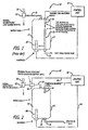
- the graph in Fig. 5 illustrates the overall benefits of the anticipation system of the present invention.
- a large water heating tank was connected to the logic controller (PCB) of a coffee maker.
- a flow switch was connected in-line on the cold water inlet.
- the flow switch was connected to the coffee maker PCB such that the heaters were turned on as soon as the flow switch detected flow.
- the line 130 represents water heater tank water temperature over a period operation of a prior art water heater tank during and after a server draw (1.5 liters) off a 4.0 liter tank, not using the temperature anticipation system of the invention.
- the line 132 represents water heater tank water temperature over the same period of operation for a water heater system, during and after a server draw (1.5 liters) off a 4.0 liter tank, utilizing the temperature anticipation system of the invention. It should be readily apparent that by being able to sense/detect whether or not the unit is flowing, the electronic controller of the present invention can turn the heaters on immediately to not only increase the overall water temperature of the hot water draw, but also to improve significantly the recovery time of the unit.
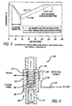
- the flow detection device may be a magnetic flow detection device 140 illustrated in Figure 6 , including a flow switch sensor housing 142, typically formed of plastic tubing, which defines a flow sensor chamber 144 confining a magnet 146 constructed to be carried along within the chamber by water flow through the housing, and movable between a non-flow sensing position at a first end 148 of the flow sensor chamber o and a flow sensing position at a second end 150 of the flow sensor chamber.
- the magnet is displaced.
- a magnetic detection sensor 152 detects the presence or absence of a magnetic field (reed switch) at the flow sensing position at a second end of the flow sensor chamber, and sends a logic signal 154 (typically a "0" or “1") to the electronic circuitry.
- the magnet is biased to be reset in its “no flow” position with a return spring 156 disposed in the flow sensor chamber and situated between a flow sensor chamber interior flange 158 and an exterior flange 160 on the magnet, although when the magnetic flow switch sensor is vertically oriented, the magnet may be reset in its "no flow” position by the force of gravity.
Landscapes
- Engineering & Computer Science (AREA)
- Food Science & Technology (AREA)
- Apparatus For Making Beverages (AREA)
- Devices For Dispensing Beverages (AREA)
- Measuring Volume Flow (AREA)
- Instantaneous Water Boilers, Portable Hot-Water Supply Apparatuses, And Control Of Portable Hot-Water Supply Apparatuses (AREA)
Claims (5)
- Wassererwärmungssystem (40) für einen Getränkezubereiter, wobei der Getränkezubereiter Folgendes einschließt:einen Wasserbehälter (42) mit einer Innenkammer (44);eine Kaltwasser-Zulaufleitung (46), welche in Fluidverbindung mit der Innenkammer (44) steht, um Wasser für den Wasserbehälter (42) bereitzustellen; undeine Warmwasser-Ablaufleitung (50), welche in Fluidverbindung mit der Innenkammer (44) steht, um erwärmtes Wasser aus dem Wasserbehälter (42) bereitzustellen, wobei die Warmwasser-Ablaufleitung (50) ein manuell zu bedienendes Warmwasserhahn-Auslassventil (52) mit einem Wasserhahnhebel (54) einschließt, der zwischen einer geöffneten Stellung (113) des Wasserhahn-Auslassventils und einer geschlossenen Stellung des Wasserhahn-Auslassventils bewegbar ist;wobei das Wassererwärmungssystem (40) Folgendes einschließt:mindestens einen Warmwasserbereiter (68), welcher mit dem Wasserbehälter (42) zur Erwärmung von Wasser in diesem Wasserbehälter (42) verbunden ist; undeine Temperaturmessvorrichtung (56), welche mit dem Wasserbehälter (42) zur Messung einer Wassertemperatur in dem Wasserbehälter (42) und zur Erzeugung eines Temperaturerfassungssignals verbunden ist;wobei das Wassererwärmungssystem (40) durch Folgendes gekennzeichnet ist:eine Zulauf-Erfassungsvorrichtung (92, 140), welche mit der Kaltwasser-Zulaufleitung (46) verbunden ist, zur Erfassung eines Zulaufs in der Kaltwasser-Zulaufleitung (46) und zur Erzeugung eines Durchfluss-Erfassungssignals; undeine logische Heizungs-Steuerschaltung, welche mit der Temperaturmessvorrichtung (56) und der Zulauf-Erfassungsvorrichtung (92, 140) wirkverbunden ist, um das Temperaturerfassungssignal und das Durchfluss-Erfassungssignal zu empfangen, wobei die logische Heizungs-Steuerschaltung mit dem mindestens einen Warmwasserbereiter (68) wirkverbunden ist und ein Warmwasserbereiter-Steuersignal zur Steuerung des Betriebs des mindestens einen Warmwasserbereiters (68) ansprechend auf das Temperaturerfassungssignal und das Durchfluss-Erfassungssignal erzeugt.
- Wassererwärmungssystem (40) nach Anspruch 1, dadurch gekennzeichnet, dass die Zulauf-Erfassungsvorrichtung (92, 140) Folgendes aufweist:ein Durchflussschalter-Sensorgehäuse (142), welches eine mit der Kaltwasser-Zulaufleitung (46) wirkverbundene Durchfluss-Sensorkammer (144) aufweist,einen Magneten (146), welcher in der Durchfluss-Sensorkammer gehalten wird und in der Durchfluss-Sensorkammer zwischen einer Nichtdurchfluss-Erkennungsposition an einem ersten Ende (148) der Durchfluss-Sensorkammer und einer Durchfluss-Erkennungsposition an einem zweiten Ende (150) der Durchfluss-Sensorkammer bewegbar ist, wobei sich der Magnet ansprechend auf einen Durchfluss in der Durchfluss-Sensorkammer in die Durchfluss-Erkennungsposition bewegt;eine in der Durchfluss-Sensorkammer angeordnete Rückstellfeder, welche betriebsbereit ist, um den Magneten in Richtung der Nichtdurchfluss-Erkennungsposition bei fehlendem Durchfluss in der Durchfluss-Sensorkammer vorzumagnetisieren; undeinen Magneterkennungssensor (152), welcher neben dem zweiten Ende der Durchfluss-Sensorkammer zur Erkennung des Magneten und zur Erzeugung des Durchfluss-Erkennungssignals angeordnet ist, wenn sich der Magnet in der Durchfluss-Erkennungsposition befindet.
- Kombination aus einem Getränkezubereiter und einem Wassererwärmungssystem (40), wobei der Getränkezubereiter Folgendes einschließt:einen Wasserbehälter (42) mit einer Innenkammer (44);eine Kaltwasser-Zulaufleitung (46), welche in Fluidverbindung mit der Innenkammer (44) steht, um Wasser für den Wasserbehälter (42) bereitzustellen;eine Warmwasser-Ablaufleitung (50), welche in Fluidverbindung mit der Innenkammer (44) steht, um erwärmtes Wasser aus dem Wasserbehälter (42) bereitzustellen, wobei die Warmwasser-Ablaufleitung (50) ein manuell zu bedienendes Warmwasserhahn-Auslassventil (52) mit einem Wasserhahnhebel einschließt, der zwischen einer geöffneten Stellung (113) des Wasserhahn-Auslassventils und einer geschlossenen Stellung des Wasserhahn-Auslassventils bewegbar ist;mindestens einen Warmwasserbereiter (68), welcher mit dem Wasserbehälter (42) zur Erwärmung von Wasser in diesem Wasserbehälter (42) verbunden ist; undeine Temperaturmessvorrichtung (56), welche mit dem Wasserbehälter (42) zur Erzeugung eines Temperaturerfassungssignals verbunden ist;wobei die Kombination durch Folgendes gekennzeichnet ist:eine Zulauf-Erfassungsvorrichtung (92, 140), welche mit der Kaltwasser-Zulaufleitung (46) verbunden ist, zur Erfassung eines Zulaufs in der Kaltwasser-Zulaufleitung (46) und zur Erzeugung eines Durchfluss-Erfassungssignals; undeine logische Heizungs-Steuerschaltung, welche mit der Temperaturmessvorrichtung (56) und der Zulauf-Erfassungsvorrichtung (92, 140) wirkverbunden ist, um das Temperaturerfassungssignal und das Durchfluss-Erfassungssignal zu empfangen, wobei die logische Heizungs-Steuerschaltung mit dem mindestens einen Warmwasserbereiter (68) wirkverbunden ist und ein Warmwasserbereiter-Steuersignal zur Steuerung des Betriebs des mindestens einen Warmwasserbereiters (68) ansprechend auf das Temperaturerfassungssignal und das Durchfluss-Erfassungssignal erzeugt.
- Kombination nach Anspruch 3, wobei die Zulauf-Erfassungsvorrichtung (92, 140) Folgendes aufweist:ein Durchflussschalter-Sensorgehäuse (142), welches eine mit der Kaltwasser-Zulaufleitung (46) wirkverbundene Durchfluss-Sensorkammer (144) aufweist,einen Magneten (146), welcher in der Durchfluss-Sensorkammer gehalten wird und in der Durchfluss-Sensorkammer zwischen einer Nichtdurchfluss-Erkennungsposition an einem ersten Ende (148) der Durchfluss-Sensorkammer und einer Durchfluss-Erkennungsposition an einem zweiten Ende (150) der Durchfluss-Sensorkammer bewegbar ist, wobei sich der Magnet ansprechend auf einen Durchfluss in der Durchfluss-Sensorkammer in die Durchfluss-Erkennungsposition bewegt;eine in der Durchfluss-Sensorkammer angeordnete Rückstellfeder, welche betriebsbereit ist, um den Magneten in Richtung der Nichtdurchfluss-Erkennungsposition bei fehlendem Durchfluss in der Durchfluss-Sensorkammer vorzumagnetisieren; undeinen Magneterkennungssensor (152), welcher neben dem zweiten Ende der Durchfluss-Sensorkammer zur Erkennung des Magneten und zur Erzeugung des Durchfluss-Erfassungssignals angeordnet ist, wenn sich der Magnet in der Durchfluss-Erkennungsposition befindet.
- Verfahren zur Steuerung der Erwärmung von Wasser in einem Getränkezubereiter, wobei der Getränkezubereiter Folgendes einschließt:einen Wasserbehälter (42) mit einer Innenkammer (44);eine Kaltwasser-Zulaufleitung (46), welche in Fluidverbindung mit der Innenkammer (44) steht, um Wasser für den Wasserbehälter (42) bereitzustellen; undeine Warmwasser-Ablaufleitung (50), welche in Fluidverbindung mit der Innenkammer (44) steht, um erwärmtes Wasser aus dem Wasserbehälter (42) bereitzustellen, wobei die Warmwasser-Ablaufleitung (50) ein manuell zu bedienendes Warmwasserhahn-Auslassventil (52) mit einem Wasserhahnhebel (54) einschließt, der zwischen einer geöffneten Stellung (113) des Wasserhahn-Auslassventils und einer geschlossenen Stellung des Wasserhahn-Auslassventils bewegbar ist; undmindestens einen Warmwasserbereiter (68), welcher mit dem Wasserbehälter (42) zur Erwärmung von Wasser in diesem Wasserbehälter (42) verbunden ist;wobei das Verfahren die folgenden Schritte aufweist:Messen einer Wassertemperatur in dem Wasserbehälter (42) und Erzeugen eines Temperaturerfassungssignals, welches die Temperatur anzeigt;wobei das Verfahren gekennzeichnet ist durch:Erfassen eines Zulaufs in der Kaltwasser-Zulaufleitung (46) und Erzeugen eines Durchfluss-Erfassungssignals, welches den Zulauf anzeigt; undBereitstellen einer logischen Heizungs-Steuerschaltung, welche das Temperaturerfassungssignal und das Durchfluss-Erfassungssignal empfängt, und Erzeugen eines Warmwasserbereiter-Steuersignals zur Steuerung des Betriebs des mindestens einen Warmwasserbereiters (68) ansprechend auf das Temperaturerfassungssignal und das Durchfluss-Erfassungssignal.
Applications Claiming Priority (2)
| Application Number | Priority Date | Filing Date | Title |
|---|---|---|---|
| US83954506P | 2006-08-23 | 2006-08-23 | |
| EP07814288A EP2073673B1 (de) | 2006-08-23 | 2007-08-21 | Flusserkennungslogik für getränkehersteller |
Related Parent Applications (1)
| Application Number | Title | Priority Date | Filing Date |
|---|---|---|---|
| EP07814288.2 Division | 2007-08-21 |
Publications (2)
| Publication Number | Publication Date |
|---|---|
| EP2428144A1 EP2428144A1 (de) | 2012-03-14 |
| EP2428144B1 true EP2428144B1 (de) | 2014-01-08 |
Family
ID=39107577
Family Applications (2)
| Application Number | Title | Priority Date | Filing Date |
|---|---|---|---|
| EP09015056.6A Active EP2428144B1 (de) | 2006-08-23 | 2007-08-21 | Wassererwärmungssystem |
| EP07814288A Active EP2073673B1 (de) | 2006-08-23 | 2007-08-21 | Flusserkennungslogik für getränkehersteller |
Family Applications After (1)
| Application Number | Title | Priority Date | Filing Date |
|---|---|---|---|
| EP07814288A Active EP2073673B1 (de) | 2006-08-23 | 2007-08-21 | Flusserkennungslogik für getränkehersteller |
Country Status (7)
| Country | Link |
|---|---|
| US (2) | US8048460B2 (de) |
| EP (2) | EP2428144B1 (de) |
| JP (2) | JP2010501824A (de) |
| AT (1) | ATE484989T1 (de) |
| CA (1) | CA2660551C (de) |
| DE (1) | DE602007010017D1 (de) |
| WO (1) | WO2008024737A2 (de) |
Families Citing this family (14)
| Publication number | Priority date | Publication date | Assignee | Title |
|---|---|---|---|---|
| PT1969979E (pt) * | 2007-03-13 | 2010-09-30 | Rancilio Macchine Caffe | Dispositivo de alimentação de água para máquinas de café |
| CL2008002963A1 (es) * | 2007-10-04 | 2010-01-22 | Nestec Sa | Dispositivo calentador para una maquina para la preparacion de alimento liquido o bebida, que comprende una unidad termica con una masa metalica, a traves de la cual circula el liquido, y acumula calor y lo suministra al liquido, y tiene uno o mas componentes electricos asegurados en forma rigida a la unidad termica; y maquina. |
| WO2009058781A1 (en) * | 2007-10-29 | 2009-05-07 | Be Intellectual Property, Inc. | Use of reed switch and magnet to detect movement of faucet handle |
| CN103505057A (zh) * | 2008-04-22 | 2014-01-15 | 雀巢产品技术援助有限公司 | 饮料制备机的模块化组件 |
| US8304699B2 (en) * | 2008-10-29 | 2012-11-06 | Be Intellectual Property, Inc. | Proximity sensor |
| EP2734898A1 (de) * | 2011-07-20 | 2014-05-28 | General Equipment And Manufacturing Company, Inc. | Drahtlose überwachung und steuerung von sicherheitsstationen in einer prozessanlage |
| US9429331B2 (en) | 2013-12-18 | 2016-08-30 | Symbol Technologies, Llc | System and method for heater power prioritization and distribution |
| CN105078260A (zh) * | 2014-05-19 | 2015-11-25 | 珠海格力电器股份有限公司 | 饮水机 |
| US11744396B1 (en) | 2015-11-10 | 2023-09-05 | Caffeine Innovations, LLC | System, method, and device for agitating coffee grounds |
| US10653266B1 (en) * | 2015-11-10 | 2020-05-19 | Caffeine Innovations, LLC | Coffee grounds stirring device |
| CN106942573B (zh) * | 2017-03-26 | 2018-05-25 | 贵州旺业农业科技有限公司 | 一种液体熟食加工设备与方法 |
| CN107687959A (zh) * | 2017-11-01 | 2018-02-13 | 中山市华源电气设备有限公司 | 一种粉冲饮料机用测试装置及其测试方法 |
| DE102021106079A1 (de) * | 2021-03-12 | 2022-09-15 | Grohe Ag | Sanitärarmatur mit einem Durchflusssensor |
| CN114001008B (zh) * | 2021-11-05 | 2023-08-18 | 骏马精密工业(惠州)有限公司 | 具有流量监测功能的电磁泵 |
Family Cites Families (25)
| Publication number | Priority date | Publication date | Assignee | Title |
|---|---|---|---|---|
| GB2098708B (en) | 1981-05-15 | 1984-09-19 | Tormen Sheet Metal Uk Ltd | A water heater |
| GB2108249A (en) | 1981-09-19 | 1983-05-11 | Thompson Instanta Limited | Catering water boilers |
| JPS6039537U (ja) * | 1983-08-26 | 1985-03-19 | リンナイ株式会社 | 感温水流スイッチ |
| US4603621A (en) * | 1984-07-23 | 1986-08-05 | Bloomfield Industries, Inc. | Beverage-making device |
| JPS6222420U (de) * | 1985-07-26 | 1987-02-10 | ||
| US5063836A (en) * | 1989-01-25 | 1991-11-12 | Cafe 98 Industries Ltd. | Coffee making machine and components thereof |
| US4978833A (en) * | 1989-01-27 | 1990-12-18 | Bunn-O-Matic Corporation | Hot water dispenser having improved water temperature control system |
| US5038752A (en) * | 1989-10-25 | 1991-08-13 | Bunn-O-Matic Corporation | Boiling water dispenser having improved water temperature control system |
| JP2507426Y2 (ja) * | 1989-11-20 | 1996-08-14 | 三浦工業株式会社 | 流れ検出装置 |
| US5285717A (en) * | 1990-07-19 | 1994-02-15 | Bunn-O-Matic Corporation | Brewer control |
| JP2910375B2 (ja) * | 1992-02-07 | 1999-06-23 | 松下電器産業株式会社 | 湯沸器 |
| JP2655223B2 (ja) * | 1992-05-22 | 1997-09-17 | ニチワ電機株式会社 | 電気湯沸器用熱源器 |
| GB9306254D0 (en) * | 1993-03-25 | 1993-05-19 | Dolphin Water Shops Ltd | Instant hot water dispenser |
| FR2714955B1 (fr) | 1994-01-13 | 1996-02-09 | Caruelle | Dispositif de commande d'une vanne du type comportant un organe rotatif d'obturation. |
| JPH08154833A (ja) * | 1994-12-09 | 1996-06-18 | Enomoto Koichi | コーヒー液抽出装置 |
| JPH08327143A (ja) * | 1995-05-30 | 1996-12-13 | Matsushita Electric Ind Co Ltd | 電気瞬間湯沸器 |
| DE19723312A1 (de) * | 1997-06-04 | 1998-12-10 | Grohe Armaturen Friedrich | Wassserauslaufventilanordnung |
| JP3054422U (ja) | 1998-05-27 | 1998-12-04 | 株式会社日本イトミック | 貯湯式電気湯沸器 |
| US6741179B2 (en) * | 1998-06-17 | 2004-05-25 | Richard Young | Apparatus for flow detection, measurement and control and system for use of same |
| EP1022569A1 (de) * | 1999-01-19 | 2000-07-26 | FUGAS s.r.l. | Magnetisch betätigter Flüssigkeitsdurchflussdetektor und diesen einbeziehende hydraulische Gruppe |
| US6164189A (en) * | 1999-10-12 | 2000-12-26 | Bunn-O-Matic Corporation | Heated water dispensing system |
| US20030033867A1 (en) * | 2001-08-16 | 2003-02-20 | Posey David Tyler | Valve monitor |
| JP2004278832A (ja) * | 2003-03-13 | 2004-10-07 | Nippon Itomic Co Ltd | 電気瞬間湯沸器 |
| AU2004235780A1 (en) * | 2003-05-02 | 2004-11-18 | Salton, Inc. | Apparatus for making brewed coffee and the like |
| US7537023B2 (en) * | 2004-01-12 | 2009-05-26 | Masco Corporation Of Indiana | Valve body assembly with electronic switching |
-
2007
- 2007-08-20 US US11/841,142 patent/US8048460B2/en active Active
- 2007-08-21 EP EP09015056.6A patent/EP2428144B1/de active Active
- 2007-08-21 DE DE602007010017T patent/DE602007010017D1/de active Active
- 2007-08-21 CA CA2660551A patent/CA2660551C/en active Active
- 2007-08-21 JP JP2009525725A patent/JP2010501824A/ja active Pending
- 2007-08-21 EP EP07814288A patent/EP2073673B1/de active Active
- 2007-08-21 WO PCT/US2007/076364 patent/WO2008024737A2/en active Application Filing
- 2007-08-21 AT AT07814288T patent/ATE484989T1/de not_active IP Right Cessation
-
2009
- 2009-07-31 US US12/533,847 patent/US20090288562A1/en not_active Abandoned
-
2013
- 2013-08-22 JP JP2013172235A patent/JP2013255832A/ja active Pending
Also Published As
| Publication number | Publication date |
|---|---|
| ATE484989T1 (de) | 2010-11-15 |
| US8048460B2 (en) | 2011-11-01 |
| CA2660551A1 (en) | 2008-02-28 |
| US20080050491A1 (en) | 2008-02-28 |
| DE602007010017D1 (de) | 2010-12-02 |
| EP2073673A2 (de) | 2009-07-01 |
| EP2428144A1 (de) | 2012-03-14 |
| JP2013255832A (ja) | 2013-12-26 |
| JP2010501824A (ja) | 2010-01-21 |
| US20090288562A1 (en) | 2009-11-26 |
| WO2008024737A3 (en) | 2008-05-08 |
| CA2660551C (en) | 2015-01-27 |
| EP2073673B1 (de) | 2010-10-20 |
| WO2008024737A2 (en) | 2008-02-28 |
Similar Documents
| Publication | Publication Date | Title |
|---|---|---|
| EP2428144B1 (de) | Wassererwärmungssystem | |
| EP0915672B1 (de) | Kaffeemaschine | |
| KR101948700B1 (ko) | 워터 디스펜싱 장치 | |
| EP2040591B1 (de) | Verfahren zur steuerung des betriebs einer vorrichtung zur ausgabe heisser flüssigkeiten | |
| US9212827B2 (en) | Flow heaters | |
| US7380523B2 (en) | Control for a fuel-fired water heating appliance having variable heating rates | |
| JP4472576B2 (ja) | ミストサウナ装置 | |
| AU2018237893B2 (en) | Espresso coffee machine with improved system for regulating the temperature of the water and method for regulating the temperature of the water in an espresso coffee machine | |
| WO2009095907A2 (en) | Water heating system | |
| KR20110020031A (ko) | 비데용 온수시스템 | |
| JP4607021B2 (ja) | ミストサウナ装置 | |
| CN215077574U (zh) | 一种带有热水泄漏报警装置的饮水机 | |
| AU2009233609A1 (en) | Control assembly | |
| KR20180002699U (ko) | 개선된 위성 배관 유닛 | |
| US11988397B2 (en) | Hot water supply control system and method for domestic electric water heaters to prevent the risk of bacterial transfer | |
| CN215650578U (zh) | 一种出水稳定的管线饮水机智能控制系统及管线饮水机 | |
| KR102560869B1 (ko) | 온수 급수기 | |
| CN218818538U (zh) | 加热龙头和水路系统 | |
| JP4701602B2 (ja) | トイレ装置 | |
| CA3102702A1 (en) | Hot water supply control system and method for domestic electric water heaters to prevent the risk of bacterial transfer | |
| JP2000111150A (ja) | 階下浴槽対応制御方法 | |
| JPH10147968A (ja) | 衛生洗浄器の火傷防止装置 | |
| JP2001108293A (ja) | 風呂自動湯張り方法 | |
| JPH1137553A (ja) | 一缶二水路式燃焼装置 | |
| JPH08284237A (ja) | 衛生洗浄器の火傷防止装置 |
Legal Events
| Date | Code | Title | Description |
|---|---|---|---|
| AC | Divisional application: reference to earlier application |
Ref document number: 2073673 Country of ref document: EP Kind code of ref document: P |
|
| AK | Designated contracting states |
Kind code of ref document: A1 Designated state(s): AT BE BG CH CY CZ DE DK EE ES FI FR GB GR HU IE IS IT LI LT LU LV MC MT NL PL PT RO SE SI SK TR |
|
| PUAI | Public reference made under article 153(3) epc to a published international application that has entered the european phase |
Free format text: ORIGINAL CODE: 0009012 |
|
| 17P | Request for examination filed |
Effective date: 20120326 |
|
| 17Q | First examination report despatched |
Effective date: 20120503 |
|
| GRAP | Despatch of communication of intention to grant a patent |
Free format text: ORIGINAL CODE: EPIDOSNIGR1 |
|
| INTG | Intention to grant announced |
Effective date: 20130718 |
|
| GRAS | Grant fee paid |
Free format text: ORIGINAL CODE: EPIDOSNIGR3 |
|
| GRAA | (expected) grant |
Free format text: ORIGINAL CODE: 0009210 |
|
| AC | Divisional application: reference to earlier application |
Ref document number: 2073673 Country of ref document: EP Kind code of ref document: P |
|
| AK | Designated contracting states |
Kind code of ref document: B1 Designated state(s): AT BE BG CH CY CZ DE DK EE ES FI FR GB GR HU IE IS IT LI LT LU LV MC MT NL PL PT RO SE SI SK TR |
|
| REG | Reference to a national code |
Ref country code: GB Ref legal event code: FG4D |
|
| REG | Reference to a national code |
Ref country code: CH Ref legal event code: EP |
|
| REG | Reference to a national code |
Ref country code: IE Ref legal event code: FG4D |
|
| REG | Reference to a national code |
Ref country code: AT Ref legal event code: REF Ref document number: 648122 Country of ref document: AT Kind code of ref document: T Effective date: 20140215 |
|
| REG | Reference to a national code |
Ref country code: DE Ref legal event code: R096 Ref document number: 602007034742 Country of ref document: DE Effective date: 20140220 |
|
| REG | Reference to a national code |
Ref country code: AT Ref legal event code: MK05 Ref document number: 648122 Country of ref document: AT Kind code of ref document: T Effective date: 20140108 |
|
| REG | Reference to a national code |
Ref country code: NL Ref legal event code: VDEP Effective date: 20140108 |
|
| REG | Reference to a national code |
Ref country code: LT Ref legal event code: MG4D |
|
| PG25 | Lapsed in a contracting state [announced via postgrant information from national office to epo] |
Ref country code: LT Free format text: LAPSE BECAUSE OF FAILURE TO SUBMIT A TRANSLATION OF THE DESCRIPTION OR TO PAY THE FEE WITHIN THE PRESCRIBED TIME-LIMIT Effective date: 20140108 Ref country code: IS Free format text: LAPSE BECAUSE OF FAILURE TO SUBMIT A TRANSLATION OF THE DESCRIPTION OR TO PAY THE FEE WITHIN THE PRESCRIBED TIME-LIMIT Effective date: 20140508 |
|
| PG25 | Lapsed in a contracting state [announced via postgrant information from national office to epo] |
Ref country code: FI Free format text: LAPSE BECAUSE OF FAILURE TO SUBMIT A TRANSLATION OF THE DESCRIPTION OR TO PAY THE FEE WITHIN THE PRESCRIBED TIME-LIMIT Effective date: 20140108 Ref country code: PT Free format text: LAPSE BECAUSE OF FAILURE TO SUBMIT A TRANSLATION OF THE DESCRIPTION OR TO PAY THE FEE WITHIN THE PRESCRIBED TIME-LIMIT Effective date: 20140508 Ref country code: CY Free format text: LAPSE BECAUSE OF FAILURE TO SUBMIT A TRANSLATION OF THE DESCRIPTION OR TO PAY THE FEE WITHIN THE PRESCRIBED TIME-LIMIT Effective date: 20140108 Ref country code: NL Free format text: LAPSE BECAUSE OF FAILURE TO SUBMIT A TRANSLATION OF THE DESCRIPTION OR TO PAY THE FEE WITHIN THE PRESCRIBED TIME-LIMIT Effective date: 20140108 Ref country code: ES Free format text: LAPSE BECAUSE OF FAILURE TO SUBMIT A TRANSLATION OF THE DESCRIPTION OR TO PAY THE FEE WITHIN THE PRESCRIBED TIME-LIMIT Effective date: 20140108 Ref country code: SE Free format text: LAPSE BECAUSE OF FAILURE TO SUBMIT A TRANSLATION OF THE DESCRIPTION OR TO PAY THE FEE WITHIN THE PRESCRIBED TIME-LIMIT Effective date: 20140108 Ref country code: AT Free format text: LAPSE BECAUSE OF FAILURE TO SUBMIT A TRANSLATION OF THE DESCRIPTION OR TO PAY THE FEE WITHIN THE PRESCRIBED TIME-LIMIT Effective date: 20140108 |
|
| PG25 | Lapsed in a contracting state [announced via postgrant information from national office to epo] |
Ref country code: BE Free format text: LAPSE BECAUSE OF FAILURE TO SUBMIT A TRANSLATION OF THE DESCRIPTION OR TO PAY THE FEE WITHIN THE PRESCRIBED TIME-LIMIT Effective date: 20140108 Ref country code: LV Free format text: LAPSE BECAUSE OF FAILURE TO SUBMIT A TRANSLATION OF THE DESCRIPTION OR TO PAY THE FEE WITHIN THE PRESCRIBED TIME-LIMIT Effective date: 20140108 |
|
| REG | Reference to a national code |
Ref country code: DE Ref legal event code: R097 Ref document number: 602007034742 Country of ref document: DE |
|
| PG25 | Lapsed in a contracting state [announced via postgrant information from national office to epo] |
Ref country code: EE Free format text: LAPSE BECAUSE OF FAILURE TO SUBMIT A TRANSLATION OF THE DESCRIPTION OR TO PAY THE FEE WITHIN THE PRESCRIBED TIME-LIMIT Effective date: 20140108 Ref country code: RO Free format text: LAPSE BECAUSE OF FAILURE TO SUBMIT A TRANSLATION OF THE DESCRIPTION OR TO PAY THE FEE WITHIN THE PRESCRIBED TIME-LIMIT Effective date: 20140108 Ref country code: CZ Free format text: LAPSE BECAUSE OF FAILURE TO SUBMIT A TRANSLATION OF THE DESCRIPTION OR TO PAY THE FEE WITHIN THE PRESCRIBED TIME-LIMIT Effective date: 20140108 Ref country code: DK Free format text: LAPSE BECAUSE OF FAILURE TO SUBMIT A TRANSLATION OF THE DESCRIPTION OR TO PAY THE FEE WITHIN THE PRESCRIBED TIME-LIMIT Effective date: 20140108 |
|
| PLBE | No opposition filed within time limit |
Free format text: ORIGINAL CODE: 0009261 |
|
| STAA | Information on the status of an ep patent application or granted ep patent |
Free format text: STATUS: NO OPPOSITION FILED WITHIN TIME LIMIT |
|
| PG25 | Lapsed in a contracting state [announced via postgrant information from national office to epo] |
Ref country code: SK Free format text: LAPSE BECAUSE OF FAILURE TO SUBMIT A TRANSLATION OF THE DESCRIPTION OR TO PAY THE FEE WITHIN THE PRESCRIBED TIME-LIMIT Effective date: 20140108 Ref country code: PL Free format text: LAPSE BECAUSE OF FAILURE TO SUBMIT A TRANSLATION OF THE DESCRIPTION OR TO PAY THE FEE WITHIN THE PRESCRIBED TIME-LIMIT Effective date: 20140108 |
|
| 26N | No opposition filed |
Effective date: 20141009 |
|
| REG | Reference to a national code |
Ref country code: DE Ref legal event code: R097 Ref document number: 602007034742 Country of ref document: DE Effective date: 20141009 |
|
| PG25 | Lapsed in a contracting state [announced via postgrant information from national office to epo] |
Ref country code: MC Free format text: LAPSE BECAUSE OF FAILURE TO SUBMIT A TRANSLATION OF THE DESCRIPTION OR TO PAY THE FEE WITHIN THE PRESCRIBED TIME-LIMIT Effective date: 20140108 Ref country code: LU Free format text: LAPSE BECAUSE OF FAILURE TO SUBMIT A TRANSLATION OF THE DESCRIPTION OR TO PAY THE FEE WITHIN THE PRESCRIBED TIME-LIMIT Effective date: 20140821 |
|
| REG | Reference to a national code |
Ref country code: CH Ref legal event code: PL |
|
| PG25 | Lapsed in a contracting state [announced via postgrant information from national office to epo] |
Ref country code: LI Free format text: LAPSE BECAUSE OF NON-PAYMENT OF DUE FEES Effective date: 20140831 Ref country code: CH Free format text: LAPSE BECAUSE OF NON-PAYMENT OF DUE FEES Effective date: 20140831 |
|
| REG | Reference to a national code |
Ref country code: IE Ref legal event code: MM4A |
|
| PG25 | Lapsed in a contracting state [announced via postgrant information from national office to epo] |
Ref country code: SI Free format text: LAPSE BECAUSE OF FAILURE TO SUBMIT A TRANSLATION OF THE DESCRIPTION OR TO PAY THE FEE WITHIN THE PRESCRIBED TIME-LIMIT Effective date: 20140108 |
|
| PG25 | Lapsed in a contracting state [announced via postgrant information from national office to epo] |
Ref country code: IE Free format text: LAPSE BECAUSE OF NON-PAYMENT OF DUE FEES Effective date: 20140821 |
|
| PG25 | Lapsed in a contracting state [announced via postgrant information from national office to epo] |
Ref country code: BG Free format text: LAPSE BECAUSE OF FAILURE TO SUBMIT A TRANSLATION OF THE DESCRIPTION OR TO PAY THE FEE WITHIN THE PRESCRIBED TIME-LIMIT Effective date: 20140108 |
|
| PG25 | Lapsed in a contracting state [announced via postgrant information from national office to epo] |
Ref country code: GR Free format text: LAPSE BECAUSE OF FAILURE TO SUBMIT A TRANSLATION OF THE DESCRIPTION OR TO PAY THE FEE WITHIN THE PRESCRIBED TIME-LIMIT Effective date: 20140409 Ref country code: MT Free format text: LAPSE BECAUSE OF FAILURE TO SUBMIT A TRANSLATION OF THE DESCRIPTION OR TO PAY THE FEE WITHIN THE PRESCRIBED TIME-LIMIT Effective date: 20140108 |
|
| PG25 | Lapsed in a contracting state [announced via postgrant information from national office to epo] |
Ref country code: HU Free format text: LAPSE BECAUSE OF FAILURE TO SUBMIT A TRANSLATION OF THE DESCRIPTION OR TO PAY THE FEE WITHIN THE PRESCRIBED TIME-LIMIT; INVALID AB INITIO Effective date: 20070821 Ref country code: TR Free format text: LAPSE BECAUSE OF FAILURE TO SUBMIT A TRANSLATION OF THE DESCRIPTION OR TO PAY THE FEE WITHIN THE PRESCRIBED TIME-LIMIT Effective date: 20140108 |
|
| REG | Reference to a national code |
Ref country code: FR Ref legal event code: PLFP Year of fee payment: 10 |
|
| REG | Reference to a national code |
Ref country code: FR Ref legal event code: PLFP Year of fee payment: 11 |
|
| REG | Reference to a national code |
Ref country code: FR Ref legal event code: PLFP Year of fee payment: 12 |
|
| P01 | Opt-out of the competence of the unified patent court (upc) registered |
Effective date: 20230630 |
|
| PGFP | Annual fee paid to national office [announced via postgrant information from national office to epo] |
Ref country code: IT Payment date: 20230720 Year of fee payment: 17 Ref country code: GB Payment date: 20230720 Year of fee payment: 17 |
|
| PGFP | Annual fee paid to national office [announced via postgrant information from national office to epo] |
Ref country code: FR Payment date: 20230720 Year of fee payment: 17 Ref country code: DE Payment date: 20230720 Year of fee payment: 17 |