EP2426769A1 - Reformeur pour pile à combustible - Google Patents
Reformeur pour pile à combustible Download PDFInfo
- Publication number
- EP2426769A1 EP2426769A1 EP10769433A EP10769433A EP2426769A1 EP 2426769 A1 EP2426769 A1 EP 2426769A1 EP 10769433 A EP10769433 A EP 10769433A EP 10769433 A EP10769433 A EP 10769433A EP 2426769 A1 EP2426769 A1 EP 2426769A1
- Authority
- EP
- European Patent Office
- Prior art keywords
- temperature
- reforming
- reforming water
- reformed gas
- combustion air
- Prior art date
- Legal status (The legal status is an assumption and is not a legal conclusion. Google has not performed a legal analysis and makes no representation as to the accuracy of the status listed.)
- Withdrawn
Links
- 0 C*1CCCC1 Chemical compound C*1CCCC1 0.000 description 1
Images


Classifications
-
- C—CHEMISTRY; METALLURGY
- C01—INORGANIC CHEMISTRY
- C01B—NON-METALLIC ELEMENTS; COMPOUNDS THEREOF; METALLOIDS OR COMPOUNDS THEREOF NOT COVERED BY SUBCLASS C01C
- C01B3/00—Hydrogen; Gaseous mixtures containing hydrogen; Separation of hydrogen from mixtures containing it; Purification of hydrogen
- C01B3/02—Production of hydrogen or of gaseous mixtures containing a substantial proportion of hydrogen
- C01B3/32—Production of hydrogen or of gaseous mixtures containing a substantial proportion of hydrogen by reaction of gaseous or liquid organic compounds with gasifying agents, e.g. water, carbon dioxide, air
- C01B3/34—Production of hydrogen or of gaseous mixtures containing a substantial proportion of hydrogen by reaction of gaseous or liquid organic compounds with gasifying agents, e.g. water, carbon dioxide, air by reaction of hydrocarbons with gasifying agents
- C01B3/38—Production of hydrogen or of gaseous mixtures containing a substantial proportion of hydrogen by reaction of gaseous or liquid organic compounds with gasifying agents, e.g. water, carbon dioxide, air by reaction of hydrocarbons with gasifying agents using catalysts
- C01B3/384—Production of hydrogen or of gaseous mixtures containing a substantial proportion of hydrogen by reaction of gaseous or liquid organic compounds with gasifying agents, e.g. water, carbon dioxide, air by reaction of hydrocarbons with gasifying agents using catalysts the catalyst being continuously externally heated
-
- C—CHEMISTRY; METALLURGY
- C01—INORGANIC CHEMISTRY
- C01B—NON-METALLIC ELEMENTS; COMPOUNDS THEREOF; METALLOIDS OR COMPOUNDS THEREOF NOT COVERED BY SUBCLASS C01C
- C01B3/00—Hydrogen; Gaseous mixtures containing hydrogen; Separation of hydrogen from mixtures containing it; Purification of hydrogen
- C01B3/02—Production of hydrogen or of gaseous mixtures containing a substantial proportion of hydrogen
- C01B3/32—Production of hydrogen or of gaseous mixtures containing a substantial proportion of hydrogen by reaction of gaseous or liquid organic compounds with gasifying agents, e.g. water, carbon dioxide, air
- C01B3/34—Production of hydrogen or of gaseous mixtures containing a substantial proportion of hydrogen by reaction of gaseous or liquid organic compounds with gasifying agents, e.g. water, carbon dioxide, air by reaction of hydrocarbons with gasifying agents
- C01B3/48—Production of hydrogen or of gaseous mixtures containing a substantial proportion of hydrogen by reaction of gaseous or liquid organic compounds with gasifying agents, e.g. water, carbon dioxide, air by reaction of hydrocarbons with gasifying agents followed by reaction of water vapour with carbon monoxide
-
- H—ELECTRICITY
- H01—ELECTRIC ELEMENTS
- H01M—PROCESSES OR MEANS, e.g. BATTERIES, FOR THE DIRECT CONVERSION OF CHEMICAL ENERGY INTO ELECTRICAL ENERGY
- H01M8/00—Fuel cells; Manufacture thereof
- H01M8/06—Combination of fuel cells with means for production of reactants or for treatment of residues
- H01M8/0606—Combination of fuel cells with means for production of reactants or for treatment of residues with means for production of gaseous reactants
- H01M8/0612—Combination of fuel cells with means for production of reactants or for treatment of residues with means for production of gaseous reactants from carbon-containing material
- H01M8/0618—Reforming processes, e.g. autothermal, partial oxidation or steam reforming
-
- H—ELECTRICITY
- H01—ELECTRIC ELEMENTS
- H01M—PROCESSES OR MEANS, e.g. BATTERIES, FOR THE DIRECT CONVERSION OF CHEMICAL ENERGY INTO ELECTRICAL ENERGY
- H01M8/00—Fuel cells; Manufacture thereof
- H01M8/06—Combination of fuel cells with means for production of reactants or for treatment of residues
- H01M8/0606—Combination of fuel cells with means for production of reactants or for treatment of residues with means for production of gaseous reactants
- H01M8/0612—Combination of fuel cells with means for production of reactants or for treatment of residues with means for production of gaseous reactants from carbon-containing material
- H01M8/0625—Combination of fuel cells with means for production of reactants or for treatment of residues with means for production of gaseous reactants from carbon-containing material in a modular combined reactor/fuel cell structure
- H01M8/0631—Reactor construction specially adapted for combination reactor/fuel cell
-
- H—ELECTRICITY
- H01—ELECTRIC ELEMENTS
- H01M—PROCESSES OR MEANS, e.g. BATTERIES, FOR THE DIRECT CONVERSION OF CHEMICAL ENERGY INTO ELECTRICAL ENERGY
- H01M8/00—Fuel cells; Manufacture thereof
- H01M8/06—Combination of fuel cells with means for production of reactants or for treatment of residues
- H01M8/0662—Treatment of gaseous reactants or gaseous residues, e.g. cleaning
- H01M8/0668—Removal of carbon monoxide or carbon dioxide
-
- C—CHEMISTRY; METALLURGY
- C01—INORGANIC CHEMISTRY
- C01B—NON-METALLIC ELEMENTS; COMPOUNDS THEREOF; METALLOIDS OR COMPOUNDS THEREOF NOT COVERED BY SUBCLASS C01C
- C01B2203/00—Integrated processes for the production of hydrogen or synthesis gas
- C01B2203/02—Processes for making hydrogen or synthesis gas
- C01B2203/0205—Processes for making hydrogen or synthesis gas containing a reforming step
- C01B2203/0227—Processes for making hydrogen or synthesis gas containing a reforming step containing a catalytic reforming step
- C01B2203/0233—Processes for making hydrogen or synthesis gas containing a reforming step containing a catalytic reforming step the reforming step being a steam reforming step
-
- C—CHEMISTRY; METALLURGY
- C01—INORGANIC CHEMISTRY
- C01B—NON-METALLIC ELEMENTS; COMPOUNDS THEREOF; METALLOIDS OR COMPOUNDS THEREOF NOT COVERED BY SUBCLASS C01C
- C01B2203/00—Integrated processes for the production of hydrogen or synthesis gas
- C01B2203/02—Processes for making hydrogen or synthesis gas
- C01B2203/0283—Processes for making hydrogen or synthesis gas containing a CO-shift step, i.e. a water gas shift step
-
- C—CHEMISTRY; METALLURGY
- C01—INORGANIC CHEMISTRY
- C01B—NON-METALLIC ELEMENTS; COMPOUNDS THEREOF; METALLOIDS OR COMPOUNDS THEREOF NOT COVERED BY SUBCLASS C01C
- C01B2203/00—Integrated processes for the production of hydrogen or synthesis gas
- C01B2203/06—Integration with other chemical processes
- C01B2203/066—Integration with other chemical processes with fuel cells
-
- C—CHEMISTRY; METALLURGY
- C01—INORGANIC CHEMISTRY
- C01B—NON-METALLIC ELEMENTS; COMPOUNDS THEREOF; METALLOIDS OR COMPOUNDS THEREOF NOT COVERED BY SUBCLASS C01C
- C01B2203/00—Integrated processes for the production of hydrogen or synthesis gas
- C01B2203/08—Methods of heating or cooling
- C01B2203/0805—Methods of heating the process for making hydrogen or synthesis gas
- C01B2203/0811—Methods of heating the process for making hydrogen or synthesis gas by combustion of fuel
- C01B2203/0822—Methods of heating the process for making hydrogen or synthesis gas by combustion of fuel the fuel containing hydrogen
-
- C—CHEMISTRY; METALLURGY
- C01—INORGANIC CHEMISTRY
- C01B—NON-METALLIC ELEMENTS; COMPOUNDS THEREOF; METALLOIDS OR COMPOUNDS THEREOF NOT COVERED BY SUBCLASS C01C
- C01B2203/00—Integrated processes for the production of hydrogen or synthesis gas
- C01B2203/08—Methods of heating or cooling
- C01B2203/0805—Methods of heating the process for making hydrogen or synthesis gas
- C01B2203/0811—Methods of heating the process for making hydrogen or synthesis gas by combustion of fuel
- C01B2203/0827—Methods of heating the process for making hydrogen or synthesis gas by combustion of fuel at least part of the fuel being a recycle stream
-
- C—CHEMISTRY; METALLURGY
- C01—INORGANIC CHEMISTRY
- C01B—NON-METALLIC ELEMENTS; COMPOUNDS THEREOF; METALLOIDS OR COMPOUNDS THEREOF NOT COVERED BY SUBCLASS C01C
- C01B2203/00—Integrated processes for the production of hydrogen or synthesis gas
- C01B2203/08—Methods of heating or cooling
- C01B2203/0872—Methods of cooling
- C01B2203/0888—Methods of cooling by evaporation of a fluid
- C01B2203/0894—Generation of steam
-
- C—CHEMISTRY; METALLURGY
- C01—INORGANIC CHEMISTRY
- C01B—NON-METALLIC ELEMENTS; COMPOUNDS THEREOF; METALLOIDS OR COMPOUNDS THEREOF NOT COVERED BY SUBCLASS C01C
- C01B2203/00—Integrated processes for the production of hydrogen or synthesis gas
- C01B2203/12—Feeding the process for making hydrogen or synthesis gas
- C01B2203/1258—Pre-treatment of the feed
-
- C—CHEMISTRY; METALLURGY
- C01—INORGANIC CHEMISTRY
- C01B—NON-METALLIC ELEMENTS; COMPOUNDS THEREOF; METALLOIDS OR COMPOUNDS THEREOF NOT COVERED BY SUBCLASS C01C
- C01B2203/00—Integrated processes for the production of hydrogen or synthesis gas
- C01B2203/12—Feeding the process for making hydrogen or synthesis gas
- C01B2203/1288—Evaporation of one or more of the different feed components
- C01B2203/1294—Evaporation by heat exchange with hot process stream
-
- C—CHEMISTRY; METALLURGY
- C01—INORGANIC CHEMISTRY
- C01B—NON-METALLIC ELEMENTS; COMPOUNDS THEREOF; METALLOIDS OR COMPOUNDS THEREOF NOT COVERED BY SUBCLASS C01C
- C01B2203/00—Integrated processes for the production of hydrogen or synthesis gas
- C01B2203/16—Controlling the process
- C01B2203/1614—Controlling the temperature
- C01B2203/1619—Measuring the temperature
-
- C—CHEMISTRY; METALLURGY
- C01—INORGANIC CHEMISTRY
- C01B—NON-METALLIC ELEMENTS; COMPOUNDS THEREOF; METALLOIDS OR COMPOUNDS THEREOF NOT COVERED BY SUBCLASS C01C
- C01B2203/00—Integrated processes for the production of hydrogen or synthesis gas
- C01B2203/16—Controlling the process
- C01B2203/1695—Adjusting the feed of the combustion
-
- Y—GENERAL TAGGING OF NEW TECHNOLOGICAL DEVELOPMENTS; GENERAL TAGGING OF CROSS-SECTIONAL TECHNOLOGIES SPANNING OVER SEVERAL SECTIONS OF THE IPC; TECHNICAL SUBJECTS COVERED BY FORMER USPC CROSS-REFERENCE ART COLLECTIONS [XRACs] AND DIGESTS
- Y02—TECHNOLOGIES OR APPLICATIONS FOR MITIGATION OR ADAPTATION AGAINST CLIMATE CHANGE
- Y02E—REDUCTION OF GREENHOUSE GAS [GHG] EMISSIONS, RELATED TO ENERGY GENERATION, TRANSMISSION OR DISTRIBUTION
- Y02E60/00—Enabling technologies; Technologies with a potential or indirect contribution to GHG emissions mitigation
- Y02E60/30—Hydrogen technology
- Y02E60/50—Fuel cells
-
- Y—GENERAL TAGGING OF NEW TECHNOLOGICAL DEVELOPMENTS; GENERAL TAGGING OF CROSS-SECTIONAL TECHNOLOGIES SPANNING OVER SEVERAL SECTIONS OF THE IPC; TECHNICAL SUBJECTS COVERED BY FORMER USPC CROSS-REFERENCE ART COLLECTIONS [XRACs] AND DIGESTS
- Y02—TECHNOLOGIES OR APPLICATIONS FOR MITIGATION OR ADAPTATION AGAINST CLIMATE CHANGE
- Y02P—CLIMATE CHANGE MITIGATION TECHNOLOGIES IN THE PRODUCTION OR PROCESSING OF GOODS
- Y02P20/00—Technologies relating to chemical industry
- Y02P20/10—Process efficiency
Definitions
- the present invention relates to a reforming apparatus for a fuel cell which generates a reformed gas containing hydrogen gas as the main component by reforming raw fuel.
- fuel cells that feature not only high energy conversion efficiency but also no hazardous substance produced by the electricity-generating reaction.
- a fuel cell which has a basic structure of an electrolyte membrane, disposed between a fuel electrode and an air electrode as with PEFC (polymer electrolyte fuel cell), and which generates power through an electrochemical reaction as described below by supplying a fuel gas containing hydrogen to the fuel electrode and supplying an oxidant gas containing oxygen to the air electrode.
- PEFC polymer electrolyte fuel cell
- Fuel electrode H 2 ⁇ 2H + +2e - (1)
- Air electrode (1/2)O 2 +2H + +2e - ⁇ H 2 O (2)
- the reformer steam-reforms the supplied raw fuel through a reaction thereof to steam and thereby generates a reformed gas containing hydrogen and carbon monoxide.
- the combustor generates a combustion exhaust gas in such a manner that raw fuel or cell offgas discharged unreacted from the fuel cell is mixed with combustion air and then they are combusted.
- the reformer is heated by this combustion exhaust gas, and thus the heat necessary for a steam-reforming reaction is supplied to the reformer.
- the temperature of a catalyst layer provided in the carbon monoxide reducer be maintained at a temperature suited for the reaction to reduce carbon monoxide.
- a method for maintaining the temperature of the catalyst layer it is conceivable to employ, for instance, a self heat recovery type structure for the reforming apparatus that adjusts the temperature of the catalyst layer by the heat possessed by the reformed gas. With this method, it is possible to maintain the temperature of the catalyst layer suited for the reduction reaction without any particular temperature control using a heater or the like.
- the controller when the temperature of the reforming water downstream of the heating unit or the temperature of the reformed gas downstream of the heat exchanger is a predetermined upper limit or above, the controller may lower the feed rate of the combustion air in such a manner as to fall below the upper limit; and when the temperature of the reforming water downstream of the heating unit or the temperature of the reformed gas downstream of the heat exchanger is a predetermined lower limit or below, the controller may raise the feed rate of the combustion air in such a manner as to exceed the lower limit.
- the reforming apparatus for a fuel cell, in the above-described embodiment may further include a temperature detector configured to detect the temperature of the steam supplied to the reformer, wherein the controller may regulate the feed rate of the combustion air to the combustor based on a detection result of the temperature detector.
- the reforming apparatus for a fuel cell, in the above-described embodiment may further include a structure by which to perform a heat exchange between the catalyst layer and the reforming water, wherein the temperature of the catalyst layer may be controlled by a heat exchange with the reforming water in addition to a heat exchange with the reformed gas supplied to the carbon monoxide reducer
- FIG. 1 is a schematic diagram showing an overall structure of a fuel cell system according to a first embodiment. It is to be noted that the schematic diagram of FIG. 1 is a diagram schematically showing mainly the functions of the constituent units and their interrelations and is not intended to limit the positional relations or arrangement of the constituent units.
- the reforming apparatus 100 is a reforming apparatus for a fuel cell which generates a reformed gas containing hydrogen gas as the main component by steam-reforming raw fuel.
- the reforming apparatus 100 includes a desulfurizer 110, a reformer 120, a combustor 130, and a carbon monoxide reducer 140 (hereinafter the carbon monoxide reducer will be referred to as "CO reducer" as appropriate).
- the desulfurizer 110 is a unit employing an adsorption system, in which a sulfur component is adsorbed by an adsorbent such as zeolite, or a so-called hydrogenation desulfurization system, in which the sulfur component is removed through a reaction of raw fuel containing a sulfur component to hydrogen in the presence of a catalyst.
- a hydrocarbon raw fuel such as kerosene, natural gas, LPG, or naphtha
- the raw fuel contains a sulfur compound as an impurity or an odorant that makes detection of gas leak easier. If the raw fuel containing the sulfur compound is sent directly to the reformer 120, the sulfur compound will act as a catalyst poison on the catalyst contained in the reformer 120 and the fuel cell 200 and the like disposed downstream of the reformer 120, which will reduce the reforming performance of the reforming apparatus 100 and the power generating performance of the fuel cell 200 by the sulfur poisoning. Hence, the sulfur compound contained in the raw fuel is removed by the desulfurizer 110.
- the desulfurizer 110 has a zeolite-based adsorbent supporting silver (Ag) (as the adsorbent). And the sulfur compound contained in the raw fuel is removed by adsorptive desulfurization reaction by this adsorbent. The raw fuel is subjected to desulfurization until the concentration of the sulfur compound reaches about 20 to 50 ppb, for instance. The raw fuel from which the sulfur compound has been removed by the desulfurizer 110 is sent to the reformer 120 or the combustor 130.
- Ag silver
- the arrangement may also be such that a catalyst layer having a Co-Mo-based or Ni-Mo-based catalyst, for instance, as a hydrogenerated desulfurization catalyst is provided, and the sulfur compound is removed through a hydrogenerated desulfurization reaction using this hydrogenerated desulfurization catalyst.
- a catalyst layer having a Co-Mo-based or Ni-Mo-based catalyst for instance, as a hydrogenerated desulfurization catalyst is provided, and the sulfur compound is removed through a hydrogenerated desulfurization reaction using this hydrogenerated desulfurization catalyst.
- the reformer 120 is provided with a reforming catalyst layer (not shown) having a Ru-based reforming catalyst with a carrier, such as alumina, supporting ruthenium (Ru) as metal particles.
- the raw fuel processed by the desulfurizer 110 and steam are supplied to the reformer 120, where a steam-reforming of the raw fuel is performed in the presence of the reforming catalyst.
- a reforming reaction takes place, in which methane in the raw fuel, for instance, and steam react to each other to produce hydrogen and carbon monoxide.
- This reforming reaction is performed within a range of about 650°C to 700°C, for instance. CH 4 +H 2 O ⁇ 3H 2 +CO (3)
- the steam required for the reforming reaction at the reformer 120 is generated by vaporing the reforming water (water for reforming use) supplied to the reformer 100.
- the reforming water is produced by processing water from the waterworks by a water treatment unit (not shown) provided with a reverse osmosis membrane, ionexchange resin, and the like.
- the water treatment unit not only lowers the electric conductivity of the water from the waterworks but also reduces organic matter having mixed therein.
- the feed rate of reforming water can be adjusted by adjusting the output of a reforming water pump 174 (reforming water supply unit).
- the reaction of reducing carbon monoxide at the catalyst layer occurs more actively on a side where the reformed gas flows in (inlet portion) than on a side where the reformed gas flows out (outlet portion), and this reaction is generally an exothermic reaction. Therefore, a preferred arrangement is such that the heat exchange with the reforming water takes place more at the inlet portion than at the outlet portion of the catalyst layer.
- the CO converter 142 has, for instance, a approximately cylindrical structure, with a conduit (not shown) for reforming water wound around the outer periphery thereof.
- the conduit for reforming water is wound three turns around the outer periphery of the inlet side of the catalyst layer and two turns around the outer periphery of the outlet side thereof.
- the reforming water having undergone a heat exchange at the CO converter 142 is further heated through a heat exchange with the combustion exhaust gas produced by the combustor 130 at a vaporizer 150 (heating unit). Then the reforming water is further heated through a heat exchange with the reformed gas discharged from the reformer 120 at a superheated steam generator 160 (heat exchanger) which is disposed downstream of the reformer 120 and upstream of the CO reducer 140.
- the reforming water is vaporized into steam, which is mixed into the raw fuel at a point downstream of the desulfurizer 110 and upstream of the reformer 120.
- the temperature of the steam is detected by a steam temperature sensor 162 (temperature detector).
- the steam temperature sensor 162 which is connected to a control unit 180 to be discussed later via a signal cable, can transmit the detected temperature of the steam as a signal to the control unit 180.
- a combustor 130 which includes a burner or the like.
- the combustor 130 mixes the raw fuel or the cell offgas (hereinbelow the raw fuel and the cell offgas being referred to collectively as "combustion fuel” as appropriate) with combustion air to burn the mixture, thereby producing a combustion exhaust gas for heating the reformer 120.
- the reformer 120 is heated by the combustion exhaust gas produced by the combustor 130 and thereby the heat necessary for the reforming reaction, which is an endothermic reaction, is obtained.
- part of the raw fuel supplied to the reforming apparatus 100 and combustion air taken in from outside the fuel cell system 10 are supplied to the combustor 130.
- the combustor 130 mixes the raw fuel and combustion air, and burn them.
- the supply of raw fuel to the combustor 130 stops and the cell offgas, which is the reformed gas discharged unreacted at the fuel cell 200, is supplied to the combustor 130.
- the combustor 130 mixes the cell offgas and combustion air, and burn them.
- the supply of raw fuel to the desulfurizer 110 and the combustor 130 is regulated by the drive of a raw fuel pump (not shown) for supplying raw fuel and the switching of a switching valve (not shown) for switching between a raw fuel conduit leading to the reformer 120 and a raw fuel conduit leading to the combustor 130.
- the drive of the raw fuel pump and the switching of the switching valve are controlled by the control unit 180.
- the air taken into the fuel cell system 10 from outside by the use of a combustion air blower 171 (air supply unit) or the like is used as air supplied to the combustor 130.
- the air taken into the fuel cell system 10 is sent to the combustor 130 after the dust and other suspended matter are removed from it with a filter (not shown).
- the amount of combustion air to be supplied to the combustor 130 can be regulated by adjusting the output of the combustion air blower 171.
- the cell offgas is sent to the combustor 130 by way of a gas-liquid separator (not shown). At the gas-liquid separator, the gas component only of the cell offgas is extracted, and the gas component is sent to the combustor 130.
- a reformed gas containing about 80% of hydrogen (fuel) and about 10% of carbon monoxide is produced from the raw fuel.
- the reformed gas thus produced is sent downstream and reaches the CO reducer 140 after the reformed gas is subjected to a heat exchange with the reforming water at the superheated steam generator 160.
- the CO reducer 140 includes a carbon monoxide converter 142 (hereinafter referred to as “CO converter” as appropriate) and a carbon monoxide remover 144 (hereinafter referred to as “CO remover” as appropriate).
- the CO converter 142 and the CO remover 144 are disposed such that the CO converter 142 is located on an upstream side, whereas the CO remover 144 on a downstream side relative to the flow of the reformed gas.
- the CO reducer 140 is provided with a heat exchanger 143, which is disposed between the CO converter 142 and the CO remover 144 on a conduit of reformed gas.
- the carbon monoxide reducer may include the CO converter 142 or the CO remover 144 only.
- the CO converter 142 which has a so-called self heat recovery type structure, is provided with a catalyst layer 142a having a Cu-Zn-based catalyst composed of pellets of copper oxide or zinc oxide, for instance, and a heat exchanger 142b for effecting a heat exchange between the reformed gas and the catalyst layer 142a.
- the reformed gas having been sent from the reformer 120 by way of the superheated steam generator 160 is first sent to the heat exchanger 142b, where a heat exchange between the reformed gas and the catalyst layer 142a is performed.
- the catalyst layer 142a is regulated to a temperature suited for a shift reaction to be discussed later.
- the concentration of carbon monoxide in the reformed gas produced by the reformer 120 is reduced to about 0.5% or below.
- the reformed gas whose carbon monoxide is reduced at the CO converter 142 is sent further downstream and reaches the CO remover 144 after the reformed gas is subjected to a heat exchange with the reforming water at the heat exchanger 143.
- the air taken into the fuel cell system 10 from outside by the use of a selective oxidation air blower 170 or the like is used as air supplied to the CO remover 144 (hereinafter referred to as "selective oxidation air" as appropriate).
- the air taken into the fuel cell system 10 is subjected to a removal of dust and other suspended matter with a filter and then supplied to the CO remover 144 after undergoing humidification and heating.
- the amount of selective oxidation air to be supplied to the CO remover 144 can be regulated by adjusting the output of the selective oxidation air blower 170.
- the arrangement may be such that a check valve (not shown) is provided on the conduit of air from outside to the reforming apparatus 100 in order to prevent the leak of raw fuel or reformed gas from the reforming apparatus 100 to the exterior.
- the concentration of carbon monoxide in the reformed gas is reduced to about 10 ppm or below.
- the reformed gas from which carbon monoxide has been selectively removed by the CO remover 144 is supplied to the anode (not shown) of the fuel cell 200 after the reformed gas is subjected to heating, humidification, and the like.
- Hydrogen as the fuel is supplied from the reforming apparatus 100. That is, the reformed gas sent from the CO reducer 140 of the reforming apparatus 100 is supplied to the anode, and the hydrogen contained in the reformed gas is used as the fuel.
- the air taken into the fuel cell system 10 from outside by the use of an oxidant blower 172 or the like is used as air as the oxidant.
- the air taken into the fuel cell system 10 is subjected to a removal of dust and other suspended matter with a filter and then supplied to the cathode of the fuel cell 200 after undergoing humidification and heating.
- the amount of air as the oxidant to be supplied to the fuel cell 200 can be regulated by adjusting the output of the oxidant blower 172.
- the arrangement may be such that a check valve (not shown) is provided on the conduit of air from outside to the fuel cell 200 in order to prevent the leak of reformed gas from the fuel cell 200 to the exterior.
- an electrode reaction as represented by formula (1) below occurs at the anode in contact with one of the faces of the solid polymer electrolyte membrane at each cell of the fuel cell 200.
- an electrode reaction as represented by formula (2) below occurs at the cathode in contact with the other of the faces of the solid polymer electrolyte membrane.
- Each cell which is cooled by the cooling water passing through a cooling water plate (not shown), is regulated to a proper temperature of about 70°C to about 80°C.
- the fuel cell system 10 is so arranged that the cooling water passing through the cooling water plate is circulated between the fuel cell 200 and the heat exchanger 210 by a circulation pump (not shown).
- the heat energy produced by the power generation of the fuel cell 200 is taken outside the fuel cell 200 by the cooling water.
- the cooling water having passed through the fuel cell 200 is again used to cool the fuel cell 200 after the cooling water is subjected to a heat exchange with heat recovery water sent from the hot water storage unit 300 at the heat exchanger 210.
- the hot water storage unit 300 has a hot water storage tank 310. Water from the waterworks is supplied to the hot water storage tank 310. The water supplied to the hot water storage tank 310 is sent out as heat recovery water by a heat recovery water pump 176 to the heat exchanger 210, where a heat exchange is performed between the heat recovery water and the cooling water discharged from the fuel cell 200. As a result, the heat recovery water is heated by the heat energy produced by the fuel cell 200, and hot water is stored in the hot water storage tank 310. Thus, the heat energy produced by the fuel cell 200 can be stored as hot water in the hot water storage tank 310, which improves the thermal efficiency of the fuel cell system 10.
- control unit 180 is connected to the reforming water pump 174 and the heat recovery water pump 176, respectively, via signal cables, and transmits the flow rate regulating signals, with which to regulate the flow rate of reforming water or recovery water, to the reforming water pump 174 and the heat recovery water pump 176, respectively.
- control unit 180 transmits and receives an electric signal among the raw fuel pump for supplying raw fuel, the switching valve for the switching between the raw fuel conduits, the circulation pump for circulating the cooling water to cool the fuel cell 200, the converter, the inverter, and so forth to thereby control each of these various types of equipment.
- the control unit 180 may be able to perform wireless infrared communication with a remote controller (not shown). In such a case, a user can control the operation of the fuel cell system 10 using the remote controller and set the temperature and the like of the hot water storage tank 310.
- the reforming apparatus 100 employs the self heat recovery type structure in the CO reducer 142 and, at the same time, controls the temperature of the catalyst layer by adjusting the feed rate of the combustion air to the combustor 130.
- the self recovery type structure in the CO reducer 142 is such that the catalyst layer is heated possessed by the reformed gas supplied to the CO reducer 140.
- the selective oxidation catalyst layer 144a of the CO remover 144 in the CO reducer 140 can also achieve the same advantageous effects as those attained by the catalyst layer 142a thereof through the similar structure and control.
- the flow rate of the combustion exhaust gas produced at the combustor 130 increases, so that the amount of heat exchange between the combustion exhaust gas that has reached the reformer 120 and the reformer 120 decreases.
- the amount of heat of the combustion exhaust gas that has passed through the reformer 120 and reached the vaporizer 150 becomes larger.
- the amount of heat that the reforming water receives from the combustion exhaust gas at the vaporizer 150 becomes larger. This reforming water is subjected to a heat exchange with the reformed gas discharged from the reformer 120 at the superheated steam generator 160.
- the amount of heat of the reforming water is large and therefore the difference in temperature between the reformed gas and the reforming water is small.
- the amount of heat exchange between the reformed gas and the reforming water decreases.
- the reformed gas is supplied to the CO converter 142 at a temperature higher than when the feed rate of the combustion air is not increased.
- the temperature of the catalyst layer 142a of the CO converter 142 can be raised. Note that increasing both the feed rate of the combustion air and the feed rate of the combustion fuel allows the temperature of the reforming catalyst layer of the reformer 120 to be kept constant.
- the amount of heat exchange between the reformed gas and the reforming water increases.
- the reformed gas is supplied to the CO converter 142 at a temperature lower than when the feed rate of the combustion air is not decreased.
- the temperature of the catalyst layer 142a of the CO converter 142 can be lowered. Note that decreasing both the feed rate of the combustion air and the feed rate of the combustion fuel allows the temperature of the reforming catalyst layer of the reformer 120 to be kept constant.
- the control unit 180 regulates the feed rate of combustion air based on the temperature of the reforming water downstream of the vaporizer 150 or based on the temperature of the reformed gas downstream of the superheated steam generator 160, and thereby controls the heating rate of the reforming water by the combustion exhaust gas at the vaporizer 150.
- the control unit 180 stores a conversion table, in which the temperature of steam (reforming water) detected by the steam temperature sensor 162 is associated with the temperature of the catalyst layer 142a, in a storage (not shown). This conversion table is prepared beforehand through experiments or simulation runs carried out by a designer.
- the control unit 180 calculates a temperature range of steam corresponding to a preferred temperature range of the catalyst layer 142a (hereinafter this temperature range will be referred to as "preferred steam temperature range" as appropriate) by the use of the conversion table, and stores the thus calculated preferred steam temperature range in the storage. Then the control unit 180 acquires the temperature of the reforming water that becomes steam after the reforming water has undergone a heat exchange with the reformed gas at the superheated steam generator 160, from a detection result of the steam temperature sensor 162 and then regulates the feed rate of combustion air in such a manner that the thus acquired temperature lies within the preferred steam temperature range. Thus the temperature of the catalyst layer 142a can be maintained within a preferred temperature range of the catalyst layer 142a.
- the "preferred temperature range of the catalyst layer 142a” is a temperature range within which the activity of catalyst contained in the catalyst layer 142 is retained.
- the control unit 180 will lower the feed rate of the combustion air so that the temperature thereof can fall below the upper limit. Also, if the temperature of steam detected by the steam temperature sensor 162 is less than or equal to the lower limit of the preferred steam temperature range, the control unit 180 will raise the feed rate of the combustion air so that the temperature thereof can exceed the lower limit.
- the control unit 180 defines the feed rate of combustion air to the combustor 130, by an air ratio.
- the air ratio is a ratio of the amount of air actually supplied to the combustor 130 over the amount of air required for the complete combustion of combustion fuel supplied to the combustor 130, and is represented by ⁇ actual feed rate of combustion air ⁇ / ⁇ the amount of air theoretically required for the complete combustion of combustion fuel ⁇ .
- the air ratio to achieve the complete combustion of combustion fuel is "1" in theory.
- an air ratio higher than the theoretical air ratio is set as the amount of air to be supplied during power generation. In other words, the fuel cell system is run by supplying an exceeding amount of air.
- the air ratio is preferably within a predetermined range. If the air ratio falls below a lower limit of the predetermined range, an incomplete burning of combustion fuel may possibly occur. If the air ratio exceeds an upper limit of the predetermined range, and it is possible that an accidental fire is caused.
- control unit 180 varies the setup value of the air ratio to regulate the temperature of steam, and regulates the feed rate of combustion air by gradually or continuously varying the output of the combustion air blower 171 so that the actual air ratio can be changed to a changed air ratio.
- control unit 180 adjusts the feed rate of combustion air so that the air ratio can lie within the aforementioned predetermined range.
- the control unit 180 stores the upper limit and the lower limit of the air ratio and a predetermined initial value in the storage.
- FIG. 2 is a control flow chart of controlling the feed rate of combustion air in the reforming apparatus according to the first embodiment. This flow is carried out by the control unit 180 and is started simultaneously with the power-on of the fuel cell system 10, for instance.
- the air ratio is first set to an initial value and the amount of combustion air associated with the initial value is supplied to the combustor 130. Then a combustion exhaust gas is produced by the combustor 130 and the temperatures of catalyst layers of the reformer 120 and the CO reducer 140 are raised by the heat produced by the combustor 130. Alternatively, the temperatures of the respective catalyst layers may be raised by a not-shown heater. As it is detected that the temperature of each catalyst layer has been raised to a predetermined temperature or above, the power generation by the fuel cell system 10 is started (Step 101 which is hereinafter abbreviated as and referred to as "S101", and other Steps will be abbreviated similarly). As a predetermined length of time has elapsed after the power-on of the fuel cell system 10, for instance, it may be determined that the temperature of each catalyst has reached the predetermined temperature or above.
- the temperature of steam As the power generation is started, it is determined from the detection result of the steam temperature sensor 162 whether the temperature of steam has exceeded 175°C or not (S102).
- the temperature of "175°C" is a lower limit of the aforementioned preferred steam temperature range. If the temperature of steam is 175°C or below (No of S102), it will be determined if a predetermined length of time, one hour, for instance, has elapsed after the start of power generation or not (S103). If one hour has not elapsed after the start of power generation (Yes of S103), it will be determined repeatedly if the temperature of steam has exceed 175°C or not (S102).
- the control of the feed rate of combustion air performed according to the present embodiment is started (S104). If one hour has elapsed after the start of power generation (No of S103), namely, if the temperature of steam has not exceeded 175°C even after one hour has elapsed after the start of power generation, the control of the feed rate of combustion air performed according to the present embodiment is started (S104).
- the feed rate of combustion air is maintained at the current feed rate for a predetermined length of time of ten minutes, for instance (S105). Subsequently, it is determined whether the temperature of steam exceeds 175°C or not (S106). If the temperature of steam exceeds 175°C (Yes of S106), the feed rate of combustion air is again maintained at the current feed rate for a predetermined length of time of ten minutes, for instance (S107). If the temperature of steam is 175°C or below (No of S106), it will be determined whether the air ratio is less than 1.6 or not (S108).
- the value "1.6" is an upper limit of the aforementioned air ratio.
- the setup value of air ratio will be set to a value larger by 0.05 and then the feed rate, of combustion air, associated with the thus changed air ratio will be supplied (S109). Then the feed rate of combustion air is maintained for ten minutes only (S105) and it is determined whether the temperature of steam exceeds 175°C or not (S106). If the air ratio is 1.6 or above (No of S108), the air ratio will remain unchanged and the feed rate of combustion air will be maintained for ten minutes only (S107).
- the temperature of steam is less than 225°C or not (S110).
- the temperature of "225°C” is an upper limit of the aforementioned preferred steam temperature range. If the temperature of steam is less than 225°C (Yes of S110), it will be determined whether the power generation has been stopped or not (S111). If the temperature of steam is 225°C or above (No of S110), it will be determined whether the air ratio exceeds 1.4 or not (S112).
- the value "1.4" is a lower limit of the aforementioned air ratio.
- the setup value of air ratio will be set to a value smaller by 0.05 and then the feed rate, of combustion air, associated with the thus changed air ratio will be supplied (S113). Then the feed rate of combustion air is maintained for ten minutes only (S107) and it is determined whether the temperature of steam becomes less than 225°C or not (S110). If the air ratio is 1.4 or less (No of S112), it will be determined if the power generation has been stopped without changing the air ratio (S111).
- the reforming water is heated by the combustion exhaust gas and then subjected to a heat exchange with the reformed gas so as to be converted into steam and supplied to the reformer 120, and the reformed gas, which has been subjected to a heat exchange with the reforming water, is supplied to the CO reducer 14. Then, as a result of the heat exchange with the reformed gas supplied to the CO reducer 140, the temperature of the catalyst layer 142a is regulated.
- the reforming apparatus 100 is provided with the steam temperature sensor 162 for detecting the temperature of steam supplied to the reformer 120, and the reforming apparatus 100 controls the temperature of catalyst layers by regulating the feed rate of combustion air based on the detection result of the steam temperature sensor 162.
- the steam temperature sensor 162 is to be installed in a conduit of steam, the mounting structure can be made simpler as compared with the case when a temperature sensor for sensing the temperature of catalyst layers is fixed to the catalyst layer.
- the number of spots to be measured can be reduced as compared with a case when the temperature of catalyst layer is directly measured.
- the manufacturing cost of the reforming apparatus 100 can be reduced, so that that the manufacturing cost of the fuel cell system 10 can be reduced.
- a heat exchange can be performed between the catalyst layer 142a of the CO converter 142 and the reforming water.
- the temperature of the catalyst layer 142a can be controlled by a heat exchange with the reforming water in addition to a heat exchange with the reformed gas.
- a higher accurate control of the temperature of catalyst layers can be performed.
- the temperature of the reforming water can be raised by the heat of the catalyst layer 142a, the thermal efficiency of the reforming apparatus as a whole can be improved.
- a reforming apparatus, for fuel cell, according to a second embodiment differs from the reforming apparatus according to the first embodiment in that the apparatus of the second embodiment regulates the feed rate of combustion air and the feed rate of reforming water so as to control the temperature of the reforming water which is subjected to a heat exchange with the reformed gas.
- the structure of a fuel cell system including the reforming apparatus for fuel cell according to the second embodiment is basically identical to that according to the first embodiment.
- the same components as those of the first embodiment are given the same reference numerals and the explanation thereof is omitted as appropriate.
- a reforming apparatus 100 regulates the amount of heat possessed by a combustion exhaust gas that reaches the vaporizer 150 and also regulates the heating rate of reforming water by the combustion exhaust gas at the vaporizer 150, by regulating the feed rate of combustion air. At the same time, the feed rate of the reforming water to the reforming apparatus 100 is also regulated. In combination of these, the temperature of the reforming water sent to the superheated steam generator 160 is regulated, thereby regulating the temperature of the reformed gas which is subjected to a heat exchange with this reforming water at the superheated steam generator 160. As a result, the temperature of the catalyst layer 142a heated by the heat possessed by this reformed gas can be regulated.
- the feed rate of the combustion air to the combustor 130 is increased, the amount of heat of the combustion exhaust gas given to the reforming water at the vaporizer 150 becomes larger as described in the first embodiment.
- the feed rate of the reforming water is decreased, the amount of the reforming water that receives heat from the combustion exhaust gas at the vaporizer 150 becomes smaller.
- the temperature of the reforming water that has passed through the vaporizer 150 and reached the superheated steam generator 160 becomes higher.
- the difference in temperature between the reformed gas and the reforming water is small and therefore the amount of heat exchange between the reformed gas and the reforming water decreases.
- the reformed gas is supplied to the CO converter 142 at a high temperature. Thereby, the temperature of the catalyst layer 142a of the CO converter 142 can be raised.
- the amount of heat of the combustion exhaust gas given to the reforming water at the vaporizer 150 becomes smaller as described in the first embodiment.
- the amount of the reforming water that receives heat from the combustion exhaust gas at the vaporizer 150 becomes larger.
- the temperature of the reforming water that has passed through the vaporizer 150 and reached the superheated steam generator 160 becomes lower.
- the difference in temperature between the reformed gas and the reforming water is large and therefore the amount of heat exchange between the reformed gas and the reforming water at the superheated steam generator 160 increases.
- the reformed gas is supplied to the CO converter 142 at a low temperature. Thereby, the temperature of the catalyst layer 142a of the CO converter 142 can be lowered.
- the temperature of the reforming water which is subjected to a heat exchange with the reformed gas is controlled in such manner that the adjustment of the feed rate of combustion air is combined with the adjustment of the feed rate of reforming water.
- the temperature of catalyst layers can be regulated with a higher accuracy.
- the control unit 180 stores a conversion table, in which the temperature of steam (reforming water) detected by the steam temperature sensor 162 is associated with the temperature of the catalyst layer 142a, in a storage. Also, the control unit 180 stores information on the preferred steam temperature range in the storage. Then the control unit 180 acquires the temperature of the reforming water that becomes steam from a detection result of the steam temperature sensor 162, and regulates the feed rate of combustion air and the feed rate of reforming water in such a manner that the thus acquired temperature lies within the preferred steam temperature range.
- control unit 180 defines the feed rate of combustion air to the combustor 130, by the air ratio.
- control unit 180 varies the setup value of the air ratio to regulate the temperature of steam, and regulates the feed rate of combustion air by gradually or continuously varying the output of the combustion air blower 171 so that the actual air ratio can be changed to a changed air ratio.
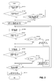
- FIG. 3 to FIG. 5 are each a control flow chart of controlling the feed rates of combustion air and reforming water in the reforming apparatus according to the second embodiment. A description is given hereunder of the second embodiment centering around differences from the first embodiment.
- the air ratio and S/C are first set to their initial values. As it is detected that the temperature of each catalyst layer has been raised to a predetermined temperature or above, the power generation by the fuel cell system 10 is started (S201).
- the feed rates of combustion air and reforming water are maintained for ten minutes only (S205). Subsequently, it is determined whether the temperature of steam exceeds 175°C or not (S206). If the temperature of steam exceeds 175°C (Yes of S206), the feed rates of combustion air and reforming water is maintained for another ten minutes only (S207). If the temperature of steam is 175°C or below (No of S206), it will be determined, as shown in FIG. 4 , whether S/C is greater than or equal to the initial value or not (S301).
- the air ratio is 1.4 or less (No of S212), it will be determined, as shown in FIG. 5 , if S/C is less than 4.0 or not (S401).
- the value "4.0" is an upper limit of the aforementioned S/C. If S/C is less than 4.0 (Yes of S401), the setup value of S/C will be set to a value larger by 0.1 and then the feed rate, of reforming water, associated with the thus changed S/C will be supplied (S402). Then, referring back to FIG. 3 , the feed rates of combustion air and reforming water are maintained for ten minutes only (S207) and it is determined whether the temperature of steam exceeds 225°C or not (S210). If, as shown in FIG.
- the heating rate of reforming water by the combustion exhaust gas is regulated by regulating the feed rate of combustion air.
- the temperature of the reforming water which is subjected to a heat exchange with the reformed gas at the superheated steam generator 160 is regulated by regulating the feed rate of reforming water.
- the temperature of the reformed gas which is subjected to a heat exchange with the reforming water at the superheated steam generator 160 can be regulated, so that the temperature of the catalyst layers of the CO reducer 140 can be regulated.
- the second embodiment achieves an advantageous effect where the temperature of the catalyst layers can be adjusted promptly with a higher accuracy.
- the solid polymer electrolyte membrane is used as the electrolyte membrane in the above-described embodiments.
- this should not be considered as limiting and, for example, an inorganic/organic complex polymer electrolyte membrane may be used instead.
- the catalysts provided in the reformer 120, the CO converter 142, and the CO remover 144 are not limited to those described above and, for example, other known catalysts may be used instead.
- the temperature of steam that has passed through the superheated steam generator 160 is detected by the steam temperature sensor 162 and thereby the feed rates of combustion air and reforming water are regulated.
- the temperature of a mixed gas of steam and raw fuel located upstream of the reformer 120 may be detected so as to thereby regulate the feed rates of combustion air and reforming water.
- the temperature of the reformed gas located upstream or down stream of the CO reducer 140 may be detected so as to thereby regulated the feed rates of combustion air and reforming water.
- the present invention is employed for a reforming apparatus for a fuel cell which generates a reformed gas containing hydrogen gas as the main component by reforming raw fuel.
Landscapes
- Chemical & Material Sciences (AREA)
- Chemical Kinetics & Catalysis (AREA)
- Engineering & Computer Science (AREA)
- Organic Chemistry (AREA)
- Life Sciences & Earth Sciences (AREA)
- Manufacturing & Machinery (AREA)
- Sustainable Development (AREA)
- Sustainable Energy (AREA)
- Electrochemistry (AREA)
- General Chemical & Material Sciences (AREA)
- Combustion & Propulsion (AREA)
- Inorganic Chemistry (AREA)
- General Health & Medical Sciences (AREA)
- Health & Medical Sciences (AREA)
- Fuel Cell (AREA)
- Hydrogen, Water And Hydrids (AREA)
Applications Claiming Priority (2)
| Application Number | Priority Date | Filing Date | Title |
|---|---|---|---|
| JP2009110058A JP5298375B2 (ja) | 2009-04-28 | 2009-04-28 | 燃料電池用改質装置 |
| PCT/JP2010/001569 WO2010125731A1 (fr) | 2009-04-28 | 2010-03-05 | Reformeur pour pile à combustible |
Publications (2)
| Publication Number | Publication Date |
|---|---|
| EP2426769A1 true EP2426769A1 (fr) | 2012-03-07 |
| EP2426769A4 EP2426769A4 (fr) | 2013-11-27 |
Family
ID=43031891
Family Applications (1)
| Application Number | Title | Priority Date | Filing Date |
|---|---|---|---|
| EP10769433.3A Withdrawn EP2426769A4 (fr) | 2009-04-28 | 2010-03-05 | Reformeur pour pile à combustible |
Country Status (4)
| Country | Link |
|---|---|
| EP (1) | EP2426769A4 (fr) |
| JP (1) | JP5298375B2 (fr) |
| KR (1) | KR20120014006A (fr) |
| WO (1) | WO2010125731A1 (fr) |
Cited By (2)
| Publication number | Priority date | Publication date | Assignee | Title |
|---|---|---|---|---|
| WO2012147420A1 (fr) * | 2011-04-28 | 2012-11-01 | Honda Motor Co., Ltd. | Système de piles à combustible |
| US9190684B2 (en) | 2011-04-28 | 2015-11-17 | Honda Motor Co., Ltd. | Fuel cell module |
Families Citing this family (5)
| Publication number | Priority date | Publication date | Assignee | Title |
|---|---|---|---|---|
| JP2014111509A (ja) * | 2011-03-30 | 2014-06-19 | Panasonic Corp | 水素生成装置及びその運転方法 |
| KR101293856B1 (ko) * | 2011-10-07 | 2013-08-07 | 현대하이스코 주식회사 | 물 예열 온도 상승을 통하여 개질 효율이 우수한 연료전지용 개질기 |
| JP6387525B2 (ja) * | 2015-01-08 | 2018-09-12 | パナソニックIpマネジメント株式会社 | 水素生成装置およびそれを備える燃料電池システム |
| JP2018014204A (ja) * | 2016-07-20 | 2018-01-25 | 株式会社デンソー | 燃料電池装置 |
| KR102041703B1 (ko) * | 2018-03-06 | 2019-11-06 | 한국가스공사 | 효율이 향상된 수소스테이션 장치 |
Citations (2)
| Publication number | Priority date | Publication date | Assignee | Title |
|---|---|---|---|---|
| US20050178063A1 (en) * | 2004-02-17 | 2005-08-18 | Reinke Michael J. | Highly integrated fuel processor for distributed hydrogen production |
| US20090087705A1 (en) * | 2007-09-27 | 2009-04-02 | Sanyo Electric Co., Ltd | Reforming apparatus for fuel cell |
Family Cites Families (9)
| Publication number | Priority date | Publication date | Assignee | Title |
|---|---|---|---|---|
| JP4556305B2 (ja) * | 2000-08-02 | 2010-10-06 | トヨタ自動車株式会社 | 燃料改質装置および水素製造方法 |
| JP4682403B2 (ja) * | 2000-08-31 | 2011-05-11 | 株式会社Ihi | Co除去装置とこれを用いた燃料電池発電装置 |
| JP4660910B2 (ja) * | 2000-10-17 | 2011-03-30 | 富士電機ホールディングス株式会社 | 燃料電池発電装置とその起動方法 |
| JP2004006093A (ja) * | 2002-05-31 | 2004-01-08 | Ebara Ballard Corp | 燃料処理装置、燃料電池発電システム |
| JP4780906B2 (ja) * | 2003-09-19 | 2011-09-28 | アイシン精機株式会社 | 燃料電池システム |
| JP4975259B2 (ja) | 2005-02-21 | 2012-07-11 | パナソニック株式会社 | 燃料電池発電装置、燃料電池発電装置の運転方法、プログラム、および記録媒体 |
| JP4902165B2 (ja) | 2005-10-17 | 2012-03-21 | 株式会社コロナ | 燃料電池用改質装置およびこの燃料電池用改質装置を備える燃料電池システム |
| JP2007261871A (ja) | 2006-03-28 | 2007-10-11 | Osaka Gas Co Ltd | 水素含有ガス生成装置 |
| JP5049028B2 (ja) | 2007-02-22 | 2012-10-17 | パナソニック株式会社 | 水素生成装置とその運転方法及びそれを備える燃料電池システム |
-
2009
- 2009-04-28 JP JP2009110058A patent/JP5298375B2/ja not_active Expired - Fee Related
-
2010
- 2010-03-05 KR KR1020117028129A patent/KR20120014006A/ko not_active Application Discontinuation
- 2010-03-05 EP EP10769433.3A patent/EP2426769A4/fr not_active Withdrawn
- 2010-03-05 WO PCT/JP2010/001569 patent/WO2010125731A1/fr active Application Filing
Patent Citations (2)
| Publication number | Priority date | Publication date | Assignee | Title |
|---|---|---|---|---|
| US20050178063A1 (en) * | 2004-02-17 | 2005-08-18 | Reinke Michael J. | Highly integrated fuel processor for distributed hydrogen production |
| US20090087705A1 (en) * | 2007-09-27 | 2009-04-02 | Sanyo Electric Co., Ltd | Reforming apparatus for fuel cell |
Non-Patent Citations (1)
| Title |
|---|
| See also references of WO2010125731A1 * |
Cited By (3)
| Publication number | Priority date | Publication date | Assignee | Title |
|---|---|---|---|---|
| WO2012147420A1 (fr) * | 2011-04-28 | 2012-11-01 | Honda Motor Co., Ltd. | Système de piles à combustible |
| US9190684B2 (en) | 2011-04-28 | 2015-11-17 | Honda Motor Co., Ltd. | Fuel cell module |
| US9653742B2 (en) | 2011-04-28 | 2017-05-16 | Honda Motor Co., Ltd. | Fuel cell system |
Also Published As
| Publication number | Publication date |
|---|---|
| JP5298375B2 (ja) | 2013-09-25 |
| EP2426769A4 (fr) | 2013-11-27 |
| KR20120014006A (ko) | 2012-02-15 |
| WO2010125731A1 (fr) | 2010-11-04 |
| JP2010257915A (ja) | 2010-11-11 |
Similar Documents
| Publication | Publication Date | Title |
|---|---|---|
| KR100762685B1 (ko) | 개질기 및 이를 채용한 연료전지 시스템 | |
| EP2426769A1 (fr) | Reformeur pour pile à combustible | |
| KR100987823B1 (ko) | 고체산화물 연료전지 시스템 | |
| JP5138324B2 (ja) | 改質器及び燃料電池システム | |
| WO2001048851A1 (fr) | Dispositif de production d'energie et procede de fonctionnement | |
| CA3081442A1 (fr) | Methode et systeme pour la generation d`energie au moyen d`une pile a combustible | |
| JP2017103218A (ja) | 固体酸化物型燃料電池システム | |
| JP2008063159A (ja) | 改質器の停止方法、改質器及び燃料電池システム | |
| JP5379353B2 (ja) | 燃料電池装置における改質器の温度制御システム | |
| JP5389520B2 (ja) | 燃料電池用改質装置 | |
| JP6719915B2 (ja) | 燃料電池−水素製造システムおよびその運転方法 | |
| JP2009026510A (ja) | 燃料電池発電システムおよび燃料電池発電システムの燃料改質方法 | |
| KR100987824B1 (ko) | 자립 고체산화물 연료전지 시스템의 운전 방법 | |
| KR101162457B1 (ko) | 고분자 전해질형 연료전지 시스템 | |
| JP4610906B2 (ja) | 燃料電池発電システム及び燃料電池発電システムの起動方法 | |
| JP5166829B2 (ja) | 改質器及び燃料電池システム | |
| JP4484585B2 (ja) | 改質装置 | |
| WO2012032744A1 (fr) | Système de pile à combustible | |
| JP2003317778A (ja) | 燃料電池の排ガス燃焼器、及び燃料電池発電システム | |
| JP5343401B2 (ja) | 発電装置及び電子機器 | |
| JP5086743B2 (ja) | 燃料電池システム | |
| JP2003317772A (ja) | 燃料電池発電システム | |
| JP2005166580A (ja) | 燃料改質装置、燃料電池システム及びそれらの運転制御方法 | |
| JP4281529B2 (ja) | 固体高分子形燃料電池発電装置 | |
| KR20130050823A (ko) | 연료전지 시스템 |
Legal Events
| Date | Code | Title | Description |
|---|---|---|---|
| PUAI | Public reference made under article 153(3) epc to a published international application that has entered the european phase |
Free format text: ORIGINAL CODE: 0009012 |
|
| 17P | Request for examination filed |
Effective date: 20111117 |
|
| AK | Designated contracting states |
Kind code of ref document: A1 Designated state(s): AT BE BG CH CY CZ DE DK EE ES FI FR GB GR HR HU IE IS IT LI LT LU LV MC MK MT NL NO PL PT RO SE SI SK SM TR |
|
| DAX | Request for extension of the european patent (deleted) | ||
| RAP1 | Party data changed (applicant data changed or rights of an application transferred) |
Owner name: JX NIPPON OIL & ENERGY CORPORATION |
|
| A4 | Supplementary search report drawn up and despatched |
Effective date: 20131030 |
|
| RIC1 | Information provided on ipc code assigned before grant |
Ipc: H01M 8/04 20060101ALI20131024BHEP Ipc: C01B 3/34 20060101ALI20131024BHEP Ipc: C01B 3/48 20060101ALI20131024BHEP Ipc: H01M 8/06 20060101AFI20131024BHEP Ipc: C01B 3/38 20060101ALI20131024BHEP Ipc: H01M 8/10 20060101ALI20131024BHEP |
|
| STAA | Information on the status of an ep patent application or granted ep patent |
Free format text: STATUS: THE APPLICATION HAS BEEN WITHDRAWN |
|
| 18W | Application withdrawn |
Effective date: 20160303 |