EP2425790B1 - Système médical et outil de traitement chirurgical - Google Patents
Système médical et outil de traitement chirurgical Download PDFInfo
- Publication number
- EP2425790B1 EP2425790B1 EP10849000.4A EP10849000A EP2425790B1 EP 2425790 B1 EP2425790 B1 EP 2425790B1 EP 10849000 A EP10849000 A EP 10849000A EP 2425790 B1 EP2425790 B1 EP 2425790B1
- Authority
- EP
- European Patent Office
- Prior art keywords
- output
- treatment
- attaching
- main body
- ultrasound
- Prior art date
- Legal status (The legal status is an assumption and is not a legal conclusion. Google has not performed a legal analysis and makes no representation as to the accuracy of the status listed.)
- Not-in-force
Links
Images


Classifications
-
- A—HUMAN NECESSITIES
- A61—MEDICAL OR VETERINARY SCIENCE; HYGIENE
- A61B—DIAGNOSIS; SURGERY; IDENTIFICATION
- A61B17/00—Surgical instruments, devices or methods, e.g. tourniquets
- A61B17/32—Surgical cutting instruments
- A61B17/320068—Surgical cutting instruments using mechanical vibrations, e.g. ultrasonic
- A61B17/320092—Surgical cutting instruments using mechanical vibrations, e.g. ultrasonic with additional movable means for clamping or cutting tissue, e.g. with a pivoting jaw
-
- A—HUMAN NECESSITIES
- A61—MEDICAL OR VETERINARY SCIENCE; HYGIENE
- A61B—DIAGNOSIS; SURGERY; IDENTIFICATION
- A61B18/00—Surgical instruments, devices or methods for transferring non-mechanical forms of energy to or from the body
- A61B18/04—Surgical instruments, devices or methods for transferring non-mechanical forms of energy to or from the body by heating
- A61B18/12—Surgical instruments, devices or methods for transferring non-mechanical forms of energy to or from the body by heating by passing a current through the tissue to be heated, e.g. high-frequency current
- A61B18/14—Probes or electrodes therefor
- A61B18/1442—Probes having pivoting end effectors, e.g. forceps
- A61B18/1445—Probes having pivoting end effectors, e.g. forceps at the distal end of a shaft, e.g. forceps or scissors at the end of a rigid rod
-
- A—HUMAN NECESSITIES
- A61—MEDICAL OR VETERINARY SCIENCE; HYGIENE
- A61B—DIAGNOSIS; SURGERY; IDENTIFICATION
- A61B17/00—Surgical instruments, devices or methods, e.g. tourniquets
- A61B2017/00477—Coupling
- A61B2017/00482—Coupling with a code
-
- A—HUMAN NECESSITIES
- A61—MEDICAL OR VETERINARY SCIENCE; HYGIENE
- A61B—DIAGNOSIS; SURGERY; IDENTIFICATION
- A61B17/00—Surgical instruments, devices or methods, e.g. tourniquets
- A61B17/32—Surgical cutting instruments
- A61B17/320068—Surgical cutting instruments using mechanical vibrations, e.g. ultrasonic
- A61B17/320092—Surgical cutting instruments using mechanical vibrations, e.g. ultrasonic with additional movable means for clamping or cutting tissue, e.g. with a pivoting jaw
- A61B2017/320093—Surgical cutting instruments using mechanical vibrations, e.g. ultrasonic with additional movable means for clamping or cutting tissue, e.g. with a pivoting jaw additional movable means performing cutting operation
-
- A—HUMAN NECESSITIES
- A61—MEDICAL OR VETERINARY SCIENCE; HYGIENE
- A61B—DIAGNOSIS; SURGERY; IDENTIFICATION
- A61B18/00—Surgical instruments, devices or methods for transferring non-mechanical forms of energy to or from the body
- A61B2018/00053—Mechanical features of the instrument of device
- A61B2018/00172—Connectors and adapters therefor
- A61B2018/00178—Electrical connectors
-
- A—HUMAN NECESSITIES
- A61—MEDICAL OR VETERINARY SCIENCE; HYGIENE
- A61B—DIAGNOSIS; SURGERY; IDENTIFICATION
- A61B18/00—Surgical instruments, devices or methods for transferring non-mechanical forms of energy to or from the body
- A61B2018/00994—Surgical instruments, devices or methods for transferring non-mechanical forms of energy to or from the body combining two or more different kinds of non-mechanical energy or combining one or more non-mechanical energies with ultrasound
Definitions
- the present invention relates to a medical apparatus and a surgical treatment instrument, and particularly relates to a medical apparatus and a surgical treatment instrument which can output at least one of an ultrasound vibration and a high-frequency current.
- Surgical treatment instruments are used for performing treatment such as dissection and coagulation of living tissue in surgical operations.
- There are types of surgical treatment instruments in accordance with the shapes of the treatment portions such as the type for performing treatment by holding living tissue (a so-called scissors-shaped type), and the type for performing treatment by being brought into contact with living tissue (for example, a hook-shaped or a spatulate type).
- an ultrasound treatment instrument capable of outputting ultrasound and a high-frequency treatment instrument capable of outputting a high-frequency current are known.
- a scissors-shaped type ultrasound treatment instrument For example, in a scissors-shaped type ultrasound treatment instrument, one member makes ultrasound vibration, whereas the other jaw member is opened and closed with respect to the one member for holding. In a spatulate type ultrasound treatment instrument, one probe with a distal end formed into a spatulate shape makes ultrasound vibration. Further, in a scissors-shaped type high-frequency treatment instrument, bipolar output of a high-frequency current is performed with use of two members, whereas in a spatulate type high-frequency treatment instrument, monopolar output is performed with use of one probe with a distal end formed into a spatulate shape and a counter electrode plate.
- Japanese Patent Application Laid-Open Publication No. 2009-78155 proposes forceps capable of both bipolar output and monopolar output in a high-frequency treatment instrument.
- a surgeon selects a treatment instrument suitable for treatment to perform the treatment.
- the treatment instrument suitable for treatment is often changed.
- Change of the treatment instrument is, for example, under observation of laparoscope, change to a spatulate ultrasound treatment instrument from a scissors-shaped ultrasound treatment instrument, or change to a spatulate high-frequency treatment instrument from a scissors-shaped high-frequency treatment instrument.
- the surgeon instructs a nurse or the like about the change, hands the treatment instrument which the surgeon has used, for example, a scissors-shaped ultrasound treatment instrument, to the nurse or the like, and receives the treatment instrument to be used next, for example, a spatulate ultrasound treatment instrument, from the nurse or the like.
- the nurse or the like removes the handed treatment instrument from the corresponding control apparatus, connects the treatment instrument to be used next by the surgeon to the corresponding control apparatus to set the treatment instrument into a usable state, and thereafter, hands the treatment instrument to the surgeon.
- the high-frequency treatment instrument proposed in the above described Japanese Patent Application Laid-Open Publication No. 2009-78155 is forceps which has the structure in which the extended portion of the monopolar element is provided at the distal end portion of one of the two members of the bipolar forceps.
- the monopolar treatment instrument and the bipolar treatment instrument do not have to be individually prepared, and a surgeon can perform treatment by monopolar output and bipolar output with one treatment instrument.
- one of the two members has a structure to allow extending the monopolar element at a distal end portion of bipolar forceps. This leads to problems that one of the members is increased in size and become complex, and that restriction on the size and shape of the monopolar element is caused. Size increase and complexity of the distal end portion and restriction on the size or the like of the monopolar element lead to deteriorated usability of the treatment instrument for the surgeon. It is also concerned that size increase of the distal end portion and restriction on the size or the like of the monopolar element deteriorate the surgeon's field of view when using a laparoscope.
- EP 2 105 099 A1 discloses an ultrasonic operating apparatus including an ultrasonic transducer which generates ultrasonic vibration, a probe unit which is coupled to the ultrasonic transducer and transmits the ultrasonic vibration from the ultrasonic transducer, an ultrasonic transducer unit having a casing section which stores the ultrasonic transducer, an electric cable which is provided at a proximal end portion of the ultrasonic transducer unit, a handle unit in which the probe unit is inserted and which includes a coupling end portion for coupling to a distal end portion of the ultrasonic transducer unit, and a coupling section which couples an outer periphery of the distal end portion of the ultrasonic transducer unit and a proximal end portion of the handle unit, wherein the coupling section includes a different-type assembly prevention section which prevents assembly between the ultrasonic transducer unit and the handle unit which are of different types.
- An objective of the present invention is to provide a medical apparatus and a surgical treatment instrument that enable, with a single treatment instrument, to easily change a surgical treatment instrument of the type of holding and treating a living tissue and a surgical treatment instrument of the type of contacting and treating a living tissue.
- a medical apparatus of one mode of the present invention includes a first device including a grasping portion grasped by a surgeon, a probe connected to the grasping portion and capable of transmitting at least one of an ultrasound vibration and a high-frequency current, and a first treatment portion which is provided at a distal end portion of the probe and is for transmitting at least one of the ultrasound vibration and the high-frequency current transmitted by the probe to living tissue, long cable means which is connected to the first device and is for supplying treatment energy including at least one of an ultrasound vibration and a high-frequency current to the first device, an energy generating apparatus which is connected to the cable means and is capable of generating the treatment energy, a second device including a second treatment portion for holding living tissue between the first treatment portion and the second treatment portion, a movable handle for holding the living tissue by moving the second treatment portion toward the first treatment portion, and an attaching and detaching portion for being attachably and detachably engaged with the first device to which the cable means is connected, and a connection signal output portion for outputting a connection
- a surgical treatment instrument of one mode of the present invention is a surgical treatment instrument having a grasping portion grasped by a surgeon, a probe which is connected to the grasping portion and is capable of transmitting at least one of an ultrasound vibration and a high-frequency current, a first treatment portion which is provided at a distal end portion of the probe and is for transmitting at least one of the ultrasound vibration and the high-frequency current which the probe transmits, to living tissue, and long cable means which is connected to the first device and is for supplying treatment energy including at least one of an ultrasound vibration and a high-frequency current to the first device, and has a connection signal output portion capable of outputting a connection signal indicating connection of a device having a second treatment portion located at a position opposed to a distal end portion of the probe when fitted to the surgical treatment instrument to which the cable means is connected.
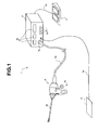
- FIG. 1 is a view showing a configuration of a surgical operation system according to an embodiment of the present invention.
- a surgical operation system 1 which is a medical apparatus is configured by including a handpiece 2, a main body apparatus 3 which is an output control apparatus, a foot switch 4 and a counter electrode plate 5.
- the handpiece 2 is a surgical treatment instrument capable of both ultrasound output and high-frequency current output.
- the handpiece 2 is connected to the main body apparatus 3 via a cable 2a which is attachable and detachable.
- the handpiece 2 has an insertion portion 2b and a handle portion 2c.
- the main body apparatus 3 as a control unit supplies at least one of a drive signal for outputting ultrasound and a drive signal for outputting a high-frequency current in accordance with setting. More specifically, the main body apparatus 3 has three output modes, that is, an ultrasound output mode, a high-frequency output mode, and a simultaneous output mode of ultrasound and high frequency. The output mode is set by various operation buttons 3c and the like provided at the main body apparatus 3. Further, the main body apparatus 3 contains a speaker (not illustrated) for outputting a sound or a voice.
- the main body apparatus 3 has a plurality of displays 3b and a plurality of various operation buttons 3c.
- the display 3b displays a set value or the like, and various operation buttons 3c are buttons for performing setting or the like of various outputs.
- the foot switch 4 is connected to the main body apparatus 3 through a cable 4a, and when a surgeon presses the foot switch 4 by foot, the foot switch 4 outputs a predetermined operation signal FS, and supplies the operation signal FS to the main body apparatus 3.
- the foot switch 4 is a switch for turning on or off ultrasound output at the time of the ultrasound output, and is a switch for turning on or off high-frequency output at the time of the high-frequency output. Setting of the output values of an ultrasound vibration and a high-frequency current is performed by operation of the operation button of an operation panel of the main body apparatus 3.
- the counter electrode plate 5 is connected to the main body apparatus 3 through a cable 5a.
- the counter electrode plate 5 is a return electrode for returning a current which passes through a subject at the time of monopolar output of a high-frequency current.
- a surgeon can perform a surgical operation under observation of laparoscope with the handpiece 2 in one hand and another treatment instrument in the other hand.
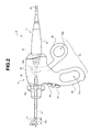
- Figs. 2 and 3 are views showing a configuration of the handpiece 2 according to the present embodiment.
- Fig. 2 is a front view showing the configuration of the handpiece 2 according to the present embodiment.
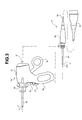
- Fig. 3 is a view showing a state in which two devices which configure the handpiece 2, that is, a first device 11 and a second device 12 are separated. As shown in Fig. 3 , the handpiece 2 is configured by the first device 11 being fitted in the second device 12.
- the first device 11 is a surgical treatment instrument having a probe 21 capable of transmitting an ultrasound vibration, a substantially columnar grasping portion 22 provided at a proximal end side of the probe 21, the cable 2a provided at a proximal end side of the grasping portion 22, and a connector portion 23 provided at a proximal end portion of the cable 2a.
- the probe 21 is a conductive shaft member which is connected to the grasping portion 22 and is capable of transmitting at least one of an ultrasound vibration and a high-frequency current.
- a distal end portion of the probe 21 is a treatment portion 21 a having a spatulate shape.
- the treatment portion 21 a is a portion which is provided at the distal end portion of the probe 21 and is for transmitting at least one of the ultrasound vibration and the high-frequency current transmitted by the probe to living tissue.
- An insulating sheath 24 is provided so that an outer peripheral portion of the probe 21 is covered with the insulating sheath 24 from a distal end portion of the grasping portion 22 to the vicinity of the distal end portion of the probe 21.
- the distal end portion of the probe 21 is protruded from a distal end opening of the insulating sheath 24. More specifically, a portion other than the treatment portion 21a of the distal end portion of the probe 21 is covered with the insulating sheath 24.
- the connector portion 23 is configured to be attachable to and detachable from a connector portion 3a of the main body apparatus 3. When the connector portion 23 is connected to the connector portion 3a, a plug in the connector portion 23 is engaged with a receptacle of the connector portion 3a. A configuration of the plug and the receptacle will be described later.
- the first device 11 has a stepped portion 25 provided with a plurality of electric armatures, between the grasping portion 22 and the insulating sheath 24.
- the stepped portion 25 includes a plurality of columnar stepped portions which are formed so that diameters become smaller stepwise from the grasping portion 22 toward the distal end of the insulating sheath 24.
- the stepped portion 25 is in a shape capable of being engaged with a recessed portion 41 of the second device so that the first device 11 can be fitted in the second device 12.
- the recessed portion 41 of the second device 12 is provided with a plurality of stepped portions in an inner peripheral portion so that the stepped portion 25 is engaged with the stepped portions. More specifically, the recessed portion 41 configures an attaching and detaching portion for the second device 12 to be attachably and detachably engaged with the first device 11.
- the first device 11 is also a surgical treatment instrument, that is, a handpiece capable of ultrasound output, high-frequency output, and simultaneous output of ultrasound and high frequency, by itself. More detailed configuration of the first device 11 will be described later.
- the second device 12 has the insertion portion 2b provided with a movable jaw 31 at a distal end portion, an operation portion main body 32 provided at a proximal end side of the insertion portion 2b, and the handle portion 2c provided at the operation portion main body 32.
- the insertion portion 2b is a tubular member made of a conductive material with an outer peripheral surface covered with an insulating layer, and has the movable jaw 31 at a distal end portion, which is pivotally supported by a pin 2b1, and is supported to be rotatable around the pin 2b1.
- a rear end of the movable jaw 31 is connected to a drive shaft (not illustrated).
- the movable jaw 31 is openable and closable in a vertical direction in Figs. 2 and 3 , through a drive shaft thereof (not illustrated) in response to an operation of the handle portion 2c.
- a rotation knob 33 for rotating the insertion portion 2b around an axis thereof is provided.
- the rotation knob 33 is fixed to an outer periphery of the proximal end portion of the insertion portion 2b. Meanwhile, the rotation knob 33 is not fixed to the operation portion main body 32, but is rotatably connected thereto. Accordingly, the rotation knob 33 is rotated, and thereby, the rotation knob 33 and the insertion portion 2b can be rotated around the longitudinal axis of the insertion portion 2b, with respect to the operation portion main body 32.
- a surgeon rotates the rotation knob 33 around the axis of the insertion portion 2b, and can set an opening and closing directions of the movable jaw 31 at an arbitrary direction.
- the handle portion 2c includes a fixed handle 34 and a movable handle 35.
- the fixed handle 34 is formed integrally with the operation portion main body 32, and has a finger rest hole 34a in which a plurality of fingers except for a thumb of a surgeon is rested.
- the movable handle 35 is pivotally supported rotatably around a pin 32a provided at the operation portion main body 32.
- the movable handle 35 has a finger rest hole 35a at which the thumb of a surgeon is rested.
- a proximal end portion of a drive shaft (not illustrated) connected to a rear end of the movable jaw 31 is connected to a spot in the vicinity of the pin 32a of the movable handle 35.
- the second device 12 is configured so that the movable jaw 31 is closed when the movable handle 35 is moved close to the fixed handle 34. More specifically, movement of the movable handle 35 with the pin 32a as the center of rotation is converted into movement of the movable jaw 31 with the support pin 2b1 as the center of rotation.
- a closed state of the movable jaw 31 is shown by a dotted line, whereas an opened state thereof is shown by a solid line.
- the movable jaw 31 is a treatment portion for holding living tissue between the treatment portion 21a and the movable jaw 31, and the movable handle 35 is an operation portion for holding living tissue by moving the movable jaw 31 which is the treatment portion toward the treatment portion 21a.
- the operation portion main body 32 is provided with two switch buttons 36 and 37.
- the switch button 36 is a switch for switching on and off ultrasound output or high-frequency current output.
- the switch 37 is a switch for changing the output value of ultrasound or high frequency. Operation signals HS of the switch buttons 36 and 37 of the operation portion main body 32 are supplied to the main body apparatus 3 through corresponding armatures 201 b and 117b, a conductive member 188 and a signal line 2ab.
- the switch buttons 36 and 37 may be allowed to function as the switches for only high-frequency output, and ultrasound output may be performed with only the foot switch 4.
- on and off of ultrasound output or high-frequency current output and the output value may be changed not only by the two switches of the operation portion main body 32, but also by the various switches 3c of the main body apparatus 3.
- Setting of the output mode and the like may be performed not only by the various switches 3c of the main body apparatus 3, but also by the two switches of the operation portion main body 32.
- the recessed portion 41 as the attaching and detaching portion for attachably and detachably engaging the first device 11 is formed.
- the second device 12 has an insertion channel 42 where the insulating sheath 24 can be inserted after the distal end of the probe 21 of the first device 11 is inserted from the recessed portion 41.
- the recessed portion 41 is formed so that the stepped portion 25 of the first device 11 is engaged therewith.
- the first device 11 When the first device 11 is fitted in the second device 12 so that the stepped portion 25 is engaged with the recessed portion 41, the first device 11 and the second device 12 are connected, and the treatment portion 21 a at the distal end portion of the probe 21 of the first device 11 is protruded from the insertion portion 2b of the second device 12 so as to be able to perform a holding operation with the movable jaw 31 of the second device.
- a treatment portion capable of holding living tissue by the distal end portion of the probe 21 and the movable jaw 31 is formed, and a plurality of electric armatures provided at the stepped portion 25 and a plurality of electric armatures provided at the recessed portion 41 are electrically connected with the armatures corresponding to each other being in contact with each other.
- the electrical connection will be described later.
- a surgeon fits the second device 12 to the first device 11, and after treatment using the scissors-shaped handpiece 2, the surgeon pulls out the handpiece 2 from a trocar provided at a body wall of a subject.
- the surgeon removes the second device 12 from the first device 11, inserts the first device 11 into the trocar, and subsequently can perform treatment using the first device 11 in a spatulate shape as the handpiece.
- the surgeon pulls out the first device 11 from the trocar provided at the body wall of the subject to fit the second device 12 thereto, inserts the first device 11 with the second device 12 fitted thereto into the trocar, and subsequently can perform the treatment using the scissors-shaped handpiece 2.
- connection signal DS from the first device 11 that the second device 12 is fitted to the first device.
- the main body apparatus 3 outputs bipolar output when the connected treatment instrument is used, for example, as a scissors-shaped high-frequency treatment instrument, and outputs monopolar output when the connected treatment instrument is used as a spatulate high-frequency treatment instrument. Further, the main body apparatus 3 changes the output value in the case of the scissors-shaped ultrasound treatment instrument and in the case of the spatulate ultrasound treatment instrument, based on the detection result.
- a configuration of the first device 11 will be described in detail.
- Fig. 4 is a sectional view of the first device 11.
- Fig. 4 is a sectional view seen from a top surface to show that the distal end portion of the probe 21 is spatulate.
- Fig. 5 is a sectional view of the grasping portion 22 of the first device 11.
- the treatment portion 21a at the distal end portion of the probe 21 is substantially straight in Figs. 2 and 3 , but since Fig. 4 is a sectional view seen from the top surface, the distal end portion is curved into a spatulate shape in Fig. 4 .
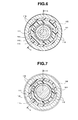
- Figs. 6 to 9 are sectional views of the grasping portion 22.
- Figs. 4 and 5 are sectional views taken along A-A lines of Figs. 6 to 9 .
- Fig. 6 is a sectional view taken along a VI-VI line of Fig. 5 .
- Fig. 7 is a sectional view taken along a VII-VII line of Fig. 5 .
- Fig. 8 is a sectional view taken along a VIII-VIII line of Fig. 5 .
- Fig. 9 is a sectional view taken along a IX-IX line of Fig. 5 .
- the first device 11 is also a surgical treatment instrument which can be used as a handpiece by itself.
- the grasping portion 22 contains an ultrasound vibration unit 101.
- the ultrasound transducer unit 101 has a vibration block which is configured into a cylindrical shape so that a plurality of piezoelectric elements 102 each formed into a donut shape are stacked with a plurality of annular electrodes 103 interposed between the adjacent piezoelectric elements.
- a bolt 104 is inserted through a through-hole in centers of the plurality of piezoelectric elements 102 and the plurality of electrodes 103 which are stacked, and the bolt 104 is screwed into a horn portion 105, whereby the plurality of piezoelectric elements 102 and the plurality of electrodes 103 are firmly brought into close contact with each other to configure the ultrasound transducer unit 101.
- the ultrasound transducer unit 101 is a unit of a Langevin type bolted ultrasound transducer.
- the ultrasound transducer unit 101 is disposed in a cylindrical casing 111.
- a plurality of signal lines of the plurality of electrodes 103 are connected to some of a plurality of signal lines 2ab in the cable 2a via a connector 112 at a proximal end portion of the casing 111.
- a distal end side of the horn portion 105 is the probe 21, and a portion 105a from the horn portion 105 to the probe configures an active line of high-frequency output.
- a flange portion 105a is formed at a proximal end portion of the horn portion 105. Further, at a predetermined position of an inner periphery of the casing 111, an inward flange portion 111a is formed. A female screw portion 111 b is formed on an inner peripheral surface of a distal end portion of the casing 111.
- the ultrasound transducer unit 101 is inserted from a distal end side of the casing 111.
- the flange portion 105a of the horn portion 105 abuts on the inward flange portion 111 a of the casing 111. With the flange portion 105a and the inward flange portion 111a abutting on each other, the horn portion 105 is fixed to the casing 111 by a cylindrical fixing member 113.
- a male screw portion 113a is formed on an outer peripheral portion of the fixing member 113, and the male screw portion 113a is screwed into the female screw portion 11 1b of the casing 111, whereby the fixing member 113 presses the horn portion 105 from the distal end side of the casing 111. Thereby, the horn portion 105 is fixed to an inside of the casing 111.
- a packing 114 made of a rubber material is provided between a proximal end portion of the fixing member 113 and the flange portion 105a.
- an O-ring 115 is provided at an outer peripheral portion of the fixing member 113. The packing 114 and the O-ring 115 prevent entry of water, blood and the like into the casing 111.
- a cylindrical cap member that is, a distal end cap 116 is fitted.
- an O-ring 116a is provided to be in close contact with the horn portion 105.
- a distal end side of the distal end cap 116 configures the stepped portion 25, and the stepped portion 25 is provided with a plurality of electric armatures 117.
- Three armatures 117a, 117b and 117c are provided respectively at three stepped portions on an outer peripheral surface of the distal end cap 116, and one armature 117d is provided on an inner peripheral surface.
- connection detecting armature 117a to which the signal line for detecting connection of the second device 12 is connected, the active line armature 117b which is connected to the signal line for the active line, and the common armature 117c which is connected to the signal line for the common line of the switch signal are provided.
- recovery line armature 117d is provided on the inner peripheral surface of the distal end cap 116. The armature 117d is exposed on a surface of the inner peripheral surface of the distal end cap 116, and is provided on an inner side of the stepped portion 25 so that the conductive member of the second device 12 can be in contact therewith as will be described later.
- the main body apparatus 3 detects that the second device 12 is fitted to the first device 11.
- the armature 117a includes two armatures, and when the armature 117a is in contact with an armature 201a at the second device 12 side which will be described later, electrical continuity is formed between the two armatures.
- the main body apparatus 3 detects the continuity state. More specifically, the armature 117a and the signal line 2ab configure a connection signal output portion or connection signal output means capable of outputting a connection signal DS indicating that the second device 12 is connected to the first device 11.
- the main body apparatus 3 changes high-frequency output to bipolar output from monopolar output in the case of the high frequency output, and changes ultrasound output to an ultrasound output value at the time of a scissors shape from an ultrasound output value at the time of a spatulate shape in the case of the ultrasound output, based on the connection signal DS.
- the three armatures 117a, 117b and 117c are formed in an annular shape along the outer peripheral surface of the stepped portion 25.
- the armature 117d is provided in an annular shape along the inner peripheral surface of the distal end cap 116.
- the armature 117d is in contact with an electric armature (not illustrated) in the second device 12 which will be described later.
- a tubular member 202 ( Fig. 14 ) made of a conductive material inside the second device 12 is electrically connected to a tubular member made of a conductive material of the insertion portion 2b.
- the armature 117d is a recovery line armature which is connected to the signal line for the recovery line at the time of high frequency output.
- the respective armatures are connected to corresponding wiring of the wiring 2ab in the cable 2a via the conductive members 118 which pass in the distal end cap 116 made of an insulating member and wiring 119 connected to the respective conductive members 118.
- the conductive member 118 which passes inside the distal end cap 116 is provided inside the distal end cap 116 by insert molding.
- An O-ring 120 is provided at the outer peripheral portion of the distal end cap 116.
- the casing 111 on which the distal end cap 116 is fitted is provided to be inserted through an inside of a second casing 121.
- the second casing 121 is a cylindrical member the diameter of which becomes smaller toward a proximal end side from a distal end side.
- the O-ring 120 is in close contact with an inner peripheral surface of the second casing 121, and the first casing 111 and the distal end cap 116 are disposed inside the second casing 121.
- a male screw portion 121 a is formed on an outer peripheral surface of the distal end side of the second casing 121. Further, a male screw portion 121b is also formed on an outer peripheral surface of a proximal end side of the second casing 121.
- the second casing 121 is further provided inside a third casing 122.
- the third casing 122 is also a cylindrical member the diameter of which becomes smaller toward a proximal end side from a distal end side.
- On an outer peripheral surface of the third casing 122 a plurality of projected portions 122a for enhancing the grasping easiness by a surgeon are formed.
- a fixing ring 123 and an end cap 124 fix the third casing 122 to hold the third casing 122 therebetween.
- the fixing ring 123 is a cylindrical member made of an insulating member, and has an inward flange portion at a distal end side.
- a female screw portion 123a is formed on an inner peripheral surface of a proximal end side of the fixing ring 123.
- the end cap 124 is a cylindrical cap member made of an insulating member, and has a stepped portion on an outer peripheral portion of a distal end side.
- a female screw portion 124a is formed on an inner peripheral surface at the distal end side of the end cap 124.
- the male screw portion 121 a of the distal end portion of the second casing 121 and the female screw portion 123a of the fixing ring 123 are screwed into each other, and the male screw portion 121 b of the proximal end portion of the second casing 121 and the female screw portion 124a of the end cap 124 are screwed into each other, whereby the third casing 122 is fixed to the fixing ring 123 and the end cap 124 to be held therebetween.
- the ultrasound transducer unit 101 is disposed in the grasping portion 22.
- the ultrasound transducer unit 101 when the first device 11 is in an ultrasound outputting state, the ultrasound transducer unit 101 generates heat. As a result, due to continuous ultrasound output, the heat generated in the ultrasound transducer unit 101 is thermally conducted in the casing of the grasping portion 22, and the temperature of the outer peripheral portion of the grasping portion 22 becomes high. The grasping portion 22 which becomes hot during a surgical operation is likely to cause reduction in operability of the handpiece 2.
- an air layer is provided between the casings of the grasping portion 22.
- a plurality of grooves 125 (125a, 125b, 125c) which are extended along an axial direction of the casing 111 are formed.
- One groove 125a is a groove for positioning with the second casing 121, and a portion which is protruded to an inner peripheral side of the second casing 121 is fitted in the groove 125a, whereby proper positioning of the first casing 111 and the second casing 121 is performed.
- the four grooves 125b are grooves for passing the conductive members 118 in the distal end cap 116 through.
- the four grooves 125c are grooves for forming air layers between the first casing 111 and the second casing 121.
- the air layers are provided between the first casing 111 and the second casing 121, whereby the heat conduction between the casings is reduced, and a temperature rise in the grasping portion 22 at the time of continuous ultrasound output can be inhibited.
- the grasping portion 22 of the first device 11 is configured with use of the three casings 111, 121 and 122.
- the air layers which are positively provided as described above are provided between the first casing 111 and the second casing 121, and therefore, a large heat insulating effect is obtained. Further, an air layer by a clearance is also formed between the second casing 121 and the third casing 122, and therefore, the insulating effect is further increased.
- the three casings are used, but four or more casings may be used, and the air layers as described above may be positively provided between the adjacent casings.
- the air layer is provided between the casings (between the first casing 111 and the second casing 121 in the present embodiment) inside the grasping portion 22, and is covered with the casing at the outermost side (the third casing 122 in the present embodiment), and therefore, when the casing 122 at the outermost side is manufactured by molding, the effect of increasing the degree of freedom of the outer shape of the casing 122 at the outermost side occurs. As a result that the degree of freedom of the outer shape of the casing 122 is increased, the casing can be formed into the shape more excellent in grasping easiness of the grasping portion 22.
- the aforementioned probe 21 is in the spatulate shape as shown in Fig. 4 , but may be in a hook shape as shown in Fig. 10.
- Fig. 10 is a sectional view of a probe 21A with a distal end portion in a hook shape seen from a top surface.
- a hook portion of the probe 2 1 A is in an S-shape to be capable of inserting the insertion channel 42 of the second device 12 therethrough.
- An inner side of the hook-shaped portion in the S-shape is a protruding portion with the sectional shape having a predetermined angle, namely, an edge portion.
- each component of the first device 11 and the second device 12 a material adaptable to high-temperature and high-pressure steam sterilization, that is, autoclaving, for example, super engineering plastics or the like is used.
- each component may be a component of an ordinary resin material.
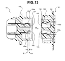
- Fig. 11 is a front view of a plug 151 in the connector portion 23.
- Fig. 12 is a front view of a receptacle 161 in the connector portion 3a.
- Fig. 13 is a sectional view taken along XIII-XIII lines of Figs. 11 and 12 for explaining connection of the plug 151 and the receptacle 161.
- the connector portion 23 of the first device 11 has the plug 151.
- the plug 151 has a cylindrical portion 153 with a center axis provided in a direction orthogonal to a plane of a base portion 152.
- the plug 151 has two protruding portions 154 and 155 which are protruded from the base portion 152.
- the first protruding portion 154 has a plurality of output terminals 154a for drive signals
- the second protruding portion 155 has a plurality of terminals 155a for switch signals and connection detecting signals.
- Each of a plurality of terminals 154a and 155a is connected to the corresponding signal line of the signal lines 2ab in the cable 2a.
- the first protruding portion 154 and the second protruding portion 155 are formed inside the cylindrical portion 153. Further, a plurality of claw portions 153a which are engaged with engaging portions 163a ( Fig. 12 ) which are provided at predetermined portions of the connector 3a are formed at a periphery of the cylindrical portion 153.
- the connector 3a has the receptacle 161.
- the receptacle 161 has a cylindrical portion 163 with a center axis provided in the direction orthogonal to a plane of a base portion 162.
- the receptacle 161 has a protruding portion 164 which is protruded from the base portion 162.
- the protruding portion 164 has two recessed portions 165 and 166.
- the two recessed portions 165 and 166 are formed toward the base portion 162 from a distal end side of the protruding portion 164.
- the protruding portion 164 is formed inside the cylindrical portion 163.
- a plurality of engaging portions 163a which are engaged with the plurality of claw portion 153a are provided at an inner peripheral portion of the cylindrical portion 163.
- the recessed portion 165 has a plurality of output terminals 165a for drive signals on an inner peripheral surface thereof, and the recessed portion 166 has a plurality of terminals 166a for switch signals and connection detection signals on an inner peripheral surface thereof.
- the respective terminals 165a and 166a are connected to corresponding circuits of the main body apparatus 3 by corresponding signal lines.
- a groove portion 154b with a semi-circular section is formed at the protruding portions 154 of the plug 151 so that the plug 151 is inserted into the receptacle 161 in a correct orientation.
- the groove portion 154b is formed parallel with the direction orthogonal to the plane of the base portion 152.
- a projected portion 165b in a semi-columnar shape which is engaged with the groove portion 154b is formed. Accordingly, only when the projected portion 165b in a semi-columnar shape is in the position where the projected portion 165b is fitted in the groove portion 154b of the plug 151, the plug 151 is inserted into the receptacle 161 in a correct orientation, and the connector portion 23 can be fitted in the connector portion 3a.
- An identifying element for identifying the kind of the first device 11, for example, a resistor is provided in the first device 11, for example, in the plug 151, though not illustrated.
- the resistor not illustrated is connected to the two terminals 155a for detecting connection.
- the plug 151 is fitted in the receptacle 161
- the two terminals 155a and the two corresponding terminals 166a at the receptacle 161 side are electrically connected, and connection of the first device 11 and the kind of the connected first device 11 can be detected in the main body apparatus 3.
- the resistor instead of the resistor, only the wiring which connects the two terminals 155a for detecting connection may be used. In that case, the main body apparatus 3 can detect connection or non-connection of the device.
- the plug 151 when the first device 11 is connected to the apparatus main body 3, the plug 151 is not sometimes suitably engaged with the receptacle 161.
- the plug 151 when the plug 151 is in a state in which the plug 151 is almost disengaged from the receptacle 161, there can be a state in which a clearance is formed between the output terminals of the drive signal.
- the plurality of output terminals 154a for drive signals and the plurality of terminals 165a for switch signals and connection detection signals are disposed at the outer peripheral portions of the protruding portions 154 and 155 so that a position S 1 where the plurality of output terminals 154a for drive signals in the plug 151 are first brought into contact with the plurality of output terminals 165a for drive signals of the receptacle 161, and a position S2 where the plurality of terminals 155a for switch signals and connection detection signals in the plug 151 are first brought into contact with the plurality of terminals 166a for switch signals and connection detection signals in the receptacle 161 are displaced in the fitting direction AA, namely, have an offset.
- the position S 1 where the plurality of output terminals 154a are first brought into contact with the plurality of output terminals 164a is separated by a distance d from the base portion 152 more than the position S2 where the plurality of terminals 155a are first brought into contact with the plurality of terminals 165a.
- the distance d is, for example, 0.8 mm.
- the connector portion 23 when the connector portion 23 is fitted in the connector portion 3a, the plurality of terminals 155a for switch signals and connection detection signals are brought into contact with the plurality of terminals 166a after the plurality of output terminals 154a for drive signals are brought into contact with the plurality of output terminals 165a.
- the first device 11 has the plug 151 as the connector portion for being connected to the main body apparatus 3, and the main body apparatus 3 has the receptacle 161 as the connector to which the plug 151 is connected.
- the armature which supplies a drive signal is disposed at a position which is displaced along the connection direction with respect to the armature which transmits an instruction signal so that the armatures which transmit instruction signals for instruction of output of drive signals are brought into contact with each other after the armatures which supply drive signals to the plug 151 are brought into contact with each other when the plug 151 and the receptacle 161 are connected along a predetermined connecting direction.
- the output terminals of a high-frequency current are connected to each other without fail when a switch signal is detected in the apparatus main body 3.
- occurrence of an electrical spark can be prevented in the clearance between the output terminals for drive signals in the plug 151 and the receptacle 161 when a surgeon turns on the switch of high-frequency output.
- Fig. 14 is a sectional view of the second device 12.
- Three electric armatures 201 a, 201 b and 201 c are provided on an inner peripheral surface of the recessed portion 41 of the operation portion main body 32.
- the three armatures 201 a, 201 b and 201 c are respectively armatures corresponding to the three armatures 117a, 117b and 117c of the first device 11.
- the three armatures 201 a, 201 b and 201 c are provided on the inner peripheral surface of the recessed portion 41 so as to be in contact with the three armatures 117a, 117b and 117c of the first device 11 respectively when the first device 11 is fitted in the second device 12.
- the tubular member 202 with a center axis coaxial with the axis of the insertion portion 2b is provided in the operation portion main body 23.
- the tubular member 202 is formed from a conductive material.
- a cutout portion not illustrated is formed at a proximal end side of the tubular member 202, and the second device 12 is configured so that the stepped portion 25 is engaged with the recessed portion 41 when the first device 11 is inserted from the proximal end side of the tubular member 202.
- An inner side of the tubular member 202 and an inner side of the insertion portion 2b form an insertion channel 42.
- a spring member 203 is provided on an outer peripheral portion of the tubular member 202 via a tubular member 204. More specifically, the tubular member 202 is inserted through the tubular member 204 made of an insulating material, and the tubular member 204 is inserted through an inner side of the spring member 203. A flange portion 204a is formed at an outer peripheral portion of the tubular member 204. A distal end side of the spring member 203 abuts on the flange portion 204a via a spring bearing member 203a.
- the spring member 203 is a constant-force spring which urges the handle 35 with a constant force in the direction to separate the movable handle 35 from the fixed handle 34, in other words, in a counterclockwise direction around the pin 32a in Fig. 14 . More specifically, the spring member 203 configures urging means which urges the movable handle 35 to rotate in the direction in which the handle portion 2c opens with the pin 32a as a center of rotation.
- a distal end portion of the tubular member 202 is electrically connected to the insertion portion 2b.
- the tubular member 202 is formed to be electrically connected to the armature 117d which is exposed on the surface of the stepped portion 25 of the first device 11 when the first device 11 and the second device 12 are coupled with each other. Accordingly, at the time of bipolar output of high-frequency output, the movable jaw 31, the insertion portion 2b and the tubular member 202, the armature 117d, and the conductive member 118 and the cable 2a configure a recovery line.
- the switches 36 and 37 are connected to the active line armature 201b and the common line armature 201c through a circuit substrate 211 of the operation portion main body 32 and a signal line 212. Accordingly, if a surgeon presses the switch 36 with a thumb at the time of high-frequency output, for example, a switch signal for outputting high-frequency output from the probe 21 is transmitted to the main body apparatus 3 through the armatures 201 b and 117b, the conductive member 118 and the cable 2a. Accordingly, when the switch 36 is pressed, the probe 21 outputs high-frequency output. Further, when the switch 37 is pressed, the output value of high-frequency output of the probe 21 is changed.
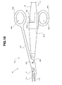
- Fig. 15 is a front view according to a modified example of the second device of the present embodiment.
- the aforementioned handpiece 2 is for use under observation of so-called laparoscope
- a second device 12A shown in Fig. 15 is a device for configuring a handpiece for celiotomy.
- the second device 12A according to the modified example is configured by having a cylindrical portion 251 having a taper portion at a distal end side, a tubular portion 252 provided at a distal end portion of the cylindrical portion 251, and a movable member 254 pivotally supported by a pin 253 provided at an outer peripheral portion of the tubular portion 252.
- a fixed handle 251b having a finger rest hole 251a at which the finger of a surgeon is rested is provided at an outer peripheral portion of the cylindrical portion 251.
- An opening portion 41 A of a proximal end portion of the cylindrical portion 251 is an opening for inserting the first device 11 from the probe 21.
- the treatment portion 21a of the probe 21 of the first device 11 which is inserted from the cylindrical portion 251 is protruded from a distal end portion of the cylindrical portion 251.
- a movable handle 254b having a finder rest hole 254a at which the thumb of a surgeon is rested is provided at a proximal end side of the movable member 254.
- a movable jaw 31A is provided at a distal end side of the movable member 254.
- An inner peripheral surface of the opening portion 41 A of the cylindrical portion 251 of the second device 12A has a shape corresponding to the stepped portion 25 and a plurality of electric armatures similarly to those of the aforementioned second device 12.
- the probe 21 of the first device 11 is inserted from the opening portion 41 A, whereby the first device 11 can be fitted in the second device 12A.
- the first device 11 is fitted in the second device 12A, whereby a scissors-shaped handpiece 2A for use at the time of celiotomy is configured.
- a surgeon can open and close a treatment portion configured by the movable jaw 31A and the treatment portion 21 a of the distal end portion of the probe 21 by operating the movable handle 254b.
- the switches 36 and 37 are provided at the operation portion main body 32.
- two switches (not illustrated) corresponding to the switches 36 and 37 may be provided at the outer peripheral portion of the grasping portion 22 of the first device 11.
- the switch corresponding to the switch 36 for high-frequency output may be provided at a position where the movable handle 254b abuts in the operation portion of the first device 11 in the state in which the first device is fitted in the second device as shown in Fig. 16 .
- the grasping portion 22 is provided with a switch for giving an instruction to output at least one of an ultrasound vibration and a high-frequency current, and the switch may be disposed at the position where the switch can be pressed by the movable handle configuring the handle portion of the second device 12, in the operation portion main body which is the grasping portion when a second device 12B is fitted.
- Fig. 16 is a view for explaining a modified example when the switch is provided at a position on which the movable handle of the first device abuts.
- a first device 11A is provided with a switch 36A at a position which is on a side surface of the grasping portion 22, and which the movable handle 254b abuts on when the movable handle 254b is closed in the state in which the first device 11A is fitted in the second device 12B.
- a cutout portion 251Aa is formed at a part of a proximal end portion of a cylindrical portion 251A so that the switch 36A is exposed.
- a surgeon can give an instruction to output high-frequency output by only performing a closing operation of the movable handle 254b in the handpiece for use at the time of celiotomy, and therefore, favorable operability is provided.
- only an operation of closing the movable handle 254b can be performed with one hand, and therefore, the operation of turning on the switch for high-frequency output with a free finger is not required, and therefore, the treatment portion at the distal end of the handpiece does not become shaky.
- the switch 36A is preferably a two-stage switch.
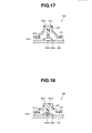
- Figs. 17 to 19 are views for explaining the configuration of the switch 36A that is a two-stage switch provided at the first device.
- Figs. 17 and 18 are sectional views for explaining the configuration of the switch 36A.
- a substantially conical pressing member 261 which is made of a rubber member or the like and has a flat portion 261 a which is flat at a distal end is provided to protrude on a surface of a casing 122 of the grasping portion 22.
- a protruding portion 261 b is formed on an inner side of the pressing member 261, that is, on a back side of the flat portion 261a.
- a conductive metal member 261c is provided at a distal end portion of the protruding portion 261b. The metal member 261c is connected to wiring not illustrated.
- a substrate 262 is placed inside the casing 122.
- a disk member 263 made of a conductive metal material is provided at a position opposed to a protruding portion 261 b on the substrate 262.
- the disk member 263 is not a flat member, but has a shape curved to be along a surface of a sphere with a central portion protruded in a direction of the protruding portion 261 b.
- the disk member 263 is connected to wiring 262a on the substrate 262, and a contact point 262b which is connected to wiring not illustrated is provided on the substrate 263 under the disk member 263.
- the pressing member 261 Since the pressing member 261 is made of a rubber member or the like, the pressing member 261 is deformed when pressed from above. As shown by the dotted line of Fig. 17 , when the pressing member 261 is deformed, the metal member 261 c at the distal end of the protruding portion 261 b is brought into contact with the disk member 263. By the contact, the wiring connected to the metal member 261c and the wiring 262a of the disk member 263 are electrically continued, and therefore, the main body apparatus 3 can detect the continuity. When the main body apparatus 3 detects the contact of the metal member 261a and the disk member 263, the main body apparatus 3 outputs a sound for informing the surgeon of the contact (hereinafter, called a first sound) by the sound through a speaker.
- a sound for informing the surgeon of the contact hereinafter, called a first sound
- the main body apparatus 3 detects the continuity, and outputs a sound for informing a surgeon of the contact by a second sound different from the first sound through the speaker, and starts output of a high-frequency current. The second sound is outputted while the central portion of the disk member 263 is in contact with the contact point 262b on the substrate.
- the pressing member 261 When the pressing member 261 is not pressed, the pressing member 261 which is an elastic member returns to the original shape as shown by the solid line of Fig. 17 , and the disk member 263 also returns to the original shape as shown by the solid line of Fig. 17 .
- the switch 36A is a two-stage switch which outputs electrical switch signals at the first stage and the second stage.
- the two-stage switch is used as the switch 36A, the surgeon can recognize that the surgeon grasps the handle portion to close the handle portion by the first sound, and further can recognize that high-frequency output is started by the second sound.
- the main body apparatus 3 makes the surgeon recognize that the surgeon grasps the handle portion by informing the surgeon of it by the first sound, and allows high-frequency output to be performed thereafter, the surgeon can reliably perform an operation of high-frequency output.
- Fig. 19 is a sectional view showing a modified example of the switch 36A.
- the switch shown in Fig. 19 is also a two-stage switch, and is a switch which generates a mechanical sound at the first stage.
- the same components as those in Figs. 17 and 18 are assigned with the same reference numerals and characters, and description thereof will be omitted.
- a substantially conical pressing member 271 which is made of a thin metal or the like and has a flat portion 271a which is flat at a distal end is provided to protrude on the surface of the casing 122 of the grasping portion 22.
- a protruding portion 271b is formed on an inner side the pressing member 271, that is, on a back side of the flat portion 271a.
- a side surface portion 271c of the pressing member 271 is in a shape slightly swelled outside as shown by the solid line of Fig. 19 when the pressing member 271 is not pressed.
- the side surface portion 271c has the shape which is deformed to be recessed inside suddenly at a certain point of time as shown by the dotted line in Fig. 19 as the pressing member 271 is gradually pressed from above and the stress of deformation is exerted thereon. At the time of instantaneous deformation of the side surface portion 271c, a mechanical sound is generated.
- the main body apparatus 3 detects the continuity.
- the main body apparatus 3 outputs a sound for informing the surgeon of the contact through the speaker, and starts output of a high-frequency current. The sound is outputted while the central portion of the disk member 263 is in contact with the contact point 262b on the substrate.
- the switch 36Aa is a two-stage switch which generates a mechanical sound at the first stage, and outputs an electrical switch signal at the second stage.
- the surgeon can reliably perform an operation of high-frequency output.
- the handpiece 2 is capable of simultaneously outputting ultrasound output and high-frequency output.
- the treatment portion 21a of the spatulate probe 21 is used in some cases for ultrasound output, in some cases for high-frequency output, and in some cases for simultaneous output of ultrasound and high frequency.
- the probe 21 has the case of configuring the scissors-shaped treatment portion in corporation with the movable jaw 31.
- the movable jaw 31 and the treatment portion 2 1 a of the probe 21 are used in some cases for ultrasound output, in some cases for high-frequency output and in some cases for simultaneous output of ultrasound and high frequency. Accordingly, the treatment portion 21a and the jaw member 31 have suitable shapes corresponding to such use states.
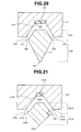
- Fig. 20 is a sectional view of the treatment portion 21 a and the jaw member 31 taken along a XX-XX line of Fig. 2 .
- the jaw member 31 has a groove 311 in which part of the insertion probe 21 is engaged, along an axial direction.
- the groove 311 has a wide channel shape with a wide opening in a section orthogonal to an axis of the jaw member 31.
- the jaw member 31 is made of a conductive material, and an insulating member 312 is provided in a range where the treatment portion 21 a is in contact along the axial direction on a bottom surface portion 313 of the channel shape.
- the treatment portion 21a has a rhombic shape partially cut out in the section orthogonal to the axial direction.
- the sectional shape of the treatment portion 21a is a shape which is cut out in the direction orthogonal to a longer diagonal line of the rhombic shape as shown in Fig. 20 .
- the treatment portion 21a with part of the rhombic shape cut out in the sectional shape has a trapezoidal portion 321 which is engaged in the groove 311 of the jaw member 31.
- a portion in which part of the rhombic shape is not cut out in the sectional shape is an isosceles triangle portion 322 in the shape of a substantially isosceles triangle of the treatment portion 21a.
- the treatment portion 21a and the jaw member 31 are fitted to each other.
- the bottom surface portion 313 of the channel-shaped groove 311 abuts on a top surface portion 323 of the trapezoidal portion 321 of the treatment portion 21a, and two inner wall portions 314 of the channel-shaped groove 311 abut on inclined surface portions 324 of the trapezoidal portion 321.
- an apex portion 325 of the isosceles triangle portion 322 of the treatment portion 21a is formed to be rounded, but the apex portion 325 has a slightly sharp angle.
- the entire treatment portion 21a acts as an ultrasound vibration treatment portion, and the apex portion 325 and its peripheral portion (shown by the dotted line) particularly act as a scalpel knife to the tissue of the treatment object.
- the apex portion 325 and its peripheral portion act as an electric scalpel knife to the tissue of the treatment object.
- the bottom surface portion 313 and the inner wall portions 314, and the top surface portion 323 and the inclined surface portions 324 act as the working surfaces of an ultrasound vibration.
- the inner wall portions 314 and the inclined surface portions 324 act as the working surfaces of a bipolar high-frequency current.
- the entire treatment portion 2 1 a acts as the ultrasound vibration treatment portion, and the apex portion 325 and its peripheral portion (shown by the dotted line) particularly act as an electrical scalpel knife to the tissue of the treatment object.
- the bottom surface portion 313 and the top surface portion 323 act as the working surfaces of an ultrasound vibration
- the inner wall portions 314 and the inclined surface portions 324 act as the working surfaces of a bipolar high-frequency current.
- Fig. 21 is a view for explaining a configuration of the treatment portion in the case of a hook-shaped probe 21 A. More specifically, Fig. 21 is a sectional view of a treatment portion 21Aa and a jaw member 31A taken along a line XXI-XXI in Fig. 10. Fig. 10 shows only the treatment portion 2 1 Aa, but Fig. 21 shows a section of the treatment portion 21Aa and the jaw member 31A in the case of the scissors-shaped treatment instrument.
- the jaw member 31A has a groove 311A in which part of the treatment portion 21Aa is engaged, along an axial direction.
- the groove 311A has a channel shape with a wide opening in a section orthogonal to an axis of the jaw member 31A.
- the jaw member 31A is made of a conductive material, and an insulating member 312A is provided along the axial direction on a bottom surface portion 313A of the channel shape.
- the treatment portion 21Aa has a rhombic shape partially cut out in the section orthogonal to the axial direction.
- the sectional shape of the treatment portion 21 Aa is a shape in which part of the rhombic shape is cut out in the direction orthogonal to one diagonal line as shown in Fig. 21 .
- the treatment portion 21Aa with part of the rhombic shape cut out in the sectional shape has a trapezoidal portion 321 A which is engaged in the groove 311 A of the j aw member 31 A.
- a portion in which part of the rhombic shape is not cut out in the sectional shape is an isosceles triangle portion 322A of the probe 21 A.
- the treatment portion 21Aa and the jaw member 31 A are fitted to each other.
- the bottom surface portion 313A of the channel-shaped groove 311 A abuts on a top surface portion 323A of the trapezoidal portion 321A of the treatment portion 21Aa, and two inner wall portions 314A of the channel-shaped groove 311A abut on inclined surface portions 324A of the trapezoidal portion 321 A.
- an apex portion 325A of the isosceles triangle portion 322A of the treatment portion 2 1 Aa is formed to be rounded, but an apex portion 326 of the inner side of the hook shape has a slightly sharp angle.
- An angle ⁇ of the apex portion 326 is preferably 45 degrees to 100 degrees. 45 degrees is a strength limit of the probe 21A.
- the apex portion 326 of the treatment portion 21Aa configures a protruding portion having a predetermined angle at the inner side of the hook-shaped portion, that is, an edge portion.
- the treatment portion in the hook shape is often used for dissection.
- the apex portion 326 of the probe 21A becomes a working portion at the time of dissection. Since the apex portion 326 has the slightly sharp angle ⁇ , the apex portion 326 is effective for dissection treatment.
- the treatment portion 21 Aa and the jaw member 31 A shown in Fig. 21 perform the same operation as the treatment portion 21a and the jaw member 31 shown in Fig. 20 at the time of ultrasound output, at the time of high-frequency output, and at the time of simultaneous output of ultrasound and high frequency respectively, except for the aforementioned operation at the time of dissection.
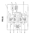
- Fig. 22 is a block diagram showing the configuration of the main body apparatus 3.
- the main body apparatus 3 is the control unit which controls output of the drive signal for supplying at least one of an ultrasound vibration and a high-frequency current to the ' first device 11.
- the main body apparatus 3 has an ultrasound output control section 51, a high-frequency output control section 61, and a switch control section 71.
- the ultrasound output control section 51 includes a control circuit 52 and an output circuit 53 which outputs a drive signal for ultrasound vibration.
- the high-frequency output control section 61 includes a control circuit 62, and an output circuit 63 which outputs a drive signal for high-frequency current output.
- the control circuits 52 and 62 are configured by various circuits of a CPU, a memory and the like.
- the control circuits 52 and 62 are connected to the display 3b and the operation button 3c of the main body apparatus 3.
- the operation signal FS from the foot switch 4 and the operation signals HS of the switches 36 and 37 of the handpiece 2 are inputted in the control circuits 52 and 62.
- the switch control section 71 receives a connection signal DS.
- the switch control section 71 supplies an output control signal to the control circuits 52 and 62 based on the connection signal DS.
- the armatures 117a and 201a are brought into contact with each other.
- the main body apparatus 3 can detect that the second device 12 is connected to the first device 11 as the connection signal DS through the signal line 2ab. Accordingly, the armature 117a and the signal line 2ab configure the connection signal output section which can output the connection signal DS which indicates that the second device 12 is connected to the first device 11.
- the output circuit 53 supplies a drive signal DR1 for ultrasound vibration to the first device 1.
- the output circuit 63 supplies a drive signal DR2 for high-frequency current output to the first device 1.
- the control circuits 52 and 62 respectively supply output control signals CS 1 and CS2 to the output circuits 53 and 63 based on setting in the operation button 3c and the operation signals from the foot switch 4 and the switches 36 and 37, and the output circuits 53 and 63 respectively output the drive signals DR1 and DR2 based on the output control signals CS 1 and CS2.
- the main body apparatus 3 outputs a drive signal for performing ultrasound output, high-frequency output or simultaneous output of ultrasound and high frequency to the handpiece 2 or the first device 11, in accordance with the setting and the operation signal.
- the main body apparatus 3 when only the first device 11 is connected, the main body apparatus 3 has three modes that are the ultrasound output mode, the high-frequency output mode and the simultaneous output mode of ultrasound and high frequency. Further, in the case of the handpiece 2 with the first device 11 fitted in the second device 12, the main body apparatus 3 has three modes that are an ultrasound output mode, a high-frequency output mode of bipolar output, and a simultaneous output mode of ultrasound and high frequency of bipolar output (or may be monopolar output).
- the main body apparatus 3 controls output of a drive signal for supplying at least one of an ultrasound vibration and a high-frequency current to the first device 11 based on the connection signal DS.
- the main body apparatus 3 controls output of the drive signal DR2 so as to switch output to bipolar output (or monopolar output) at the time of output of a high-frequency current, and controls output of the drive signal DR1 so as to switch output to ultrasound drive output suitable for treatment by the scissors-shaped treatment portion at the time of output of an ultrasound vibration.
- the main body apparatus 3 controls the output of the drive signal DR2 so as to switch the output to monopolar output at the time of output of a high-frequency current, and controls the output of the drive signal DR1 so as to switch the output to the ultrasound drive output suitable for treatment by the spatulate treatment portion at the time of output of an ultrasound vibration.
- the main body apparatus 3 controls output of the drive signals DR1 and DR2 so as to switch the output to the simultaneous output of an ultrasound vibration and a high-frequency current of bipolar output (or monopolar output) suitable for the treatment by the scissors-shaped treatment portion at the time of simultaneous output of an ultrasound vibration and a high-frequency current.
- the main body apparatus 3 controls output of the drive signals DR1 and DR2 so as to switch the output to the aforesaid ultrasound vibration output of ultrasound drive output suitable for the treatment by the spatulate treatment portion, the aforesaid high-frequency current output of monopolar output, or simultaneous output of an ultrasound vibration and a high-frequency current of monopolar output suitable for the treatment by the spatulate treatment portion.
- the main body apparatus 3 can automatically control the output of the drive signal for supplying at least one of an ultrasound vibration and a high-frequency current to the first device 11 based on the connection signal DS.
- the main body apparatus 3 based on the connection signal DS, the main body apparatus 3 automatically performs change of the output, for example, change of bipolar and monopolar, change of the output value of ultrasound output, or the like, but the main body apparatus 3 may inform a surgeon of the connection situation of the first device 11 and the second device 12 by lighting a predetermined lamp or the like based on the connection signal DS, and the surgeon may perform switch of the output in the operation button or the like of the main body apparatus 3.
- the handpiece 2 can individually or simultaneously output both high-frequency output and ultrasound output, but the output switch control of the present embodiment also can be applied to the handpiece capable of only high-frequency output or the handpiece capable of only ultrasound output.
- the main body apparatus 3 makes high-frequency output monopolar output in the case of only the first device, and switch the output so as to make high-frequency output bipolar output when the first device is connected to the second device, based on the connection signal DS.
- the main body apparatus 3 outputs ultrasound output in the first set value suitable for the spatulate treatment portion in the case of only the first device, and switches the output to output ultrasound output in the second set value suitable for the scissors-shaped treatment portion when the first device is coupled to the second device, based on the connection signal DS.
- the medical apparatus and the surgical treatment instrument can be realized, which are capable of easily changing the surgical treatment instrument of the type for performing treatment by holding living tissue, and the surgical treatment instrument of the type for performing treatment by being brought into contact with living tissue in one treatment instrument.
- the high-frequency treatment instrument proposed in the above described Japanese Patent Application Laid-Open Publication No. 2009-78155 is the forceps having the structure in which the extended portion of the monopolar element is provided at the distal end portion of one of the two members of the bipolar forceps. According to the high-frequency treatment instrument, there is no need of preparing the monopolar treatment instrument and the bipolar treatment instrument respectively, and the surgeon can perform treatment by monopolar output and bipolar output with one treatment instrument.
- the high-frequency treatment instrument according to the proposal has the structure for making the monopolar element extendable in one of the two members in the distal end portion of the bipolar forceps, there arise the problems that the one member is increased in size and is complicated, and limitation occurs in the size and shape of the monopolar element.
- Increase in size and complication of the distal end portion and limitation of the size and the like of the monopolar element lead to degradation of usability of the treatment instrument for a surgeon, and due to increase in size of the distal end portion and limitation of the size and the like of the monopolar element, the field of view of a surgeon is likely to be worsened under observation of laparoscope.
- the medical apparatus and the surgical treatment instrument can be realized, which are capable of easily changing the surgical treatment instrument of the type for performing treatment by holding living tissue, and the surgical treatment instrument of the type for performing treatment by being brought into contact with living tissue in one treatment instrument.
- the present invention is not limited to the aforementioned embodiment, and various changes, modifications and the like can be made within the range without changing the gist of the present invention.
Claims (9)
- Appareil médical comprenant un premier dispositif (11) et un deuxième dispositif (12), l'appareil médical comprenant,
un appareil de corps principal (3) capable de délivrer en sortie au moins l'un parmi un signal d'entraînement ultrasonore pour des vibrations ultrasonores et un signal d'entraînement haute fréquence pour un courant haute fréquence ;
dans lequel le premier dispositif (11) comprend une sonde (21) destinée à transmettre au moins l'un parmi des vibrations ultrasonores et un courant haute fréquence, et réaliser un premier traitement sur un tissu vivant avec une première partie de traitement (21a) formée au niveau d'une partie d'extrémité distale ;
une première partie de préhension (22) connectée à la sonde (21) et connectée à l'appareil de corps principal (3) via un câble, et appropriée pour être saisie par un chirurgien lors de l'exécution du premier traitement ;
une première partie de fixation et de séparation prévue sur la première partie de préhension (22) et incluant une première armature électrique (117) ; et
le deuxième dispositif (12) comprend une partie d'insertion (2b) incluant un canal d'insertion (42) dans lequel la sonde (21) peut être insérée, et incluant en outre une deuxième partie de traitement (31) qui, lorsque la sonde (21) est insérée dans le canal d'insertion (42), est appropriée pour maintenir le tissu vivant entre la deuxième partie de traitement (31) et la première partie de traitement (21a) au niveau d'une position opposée à la première partie de traitement (21a) et réaliser un deuxième traitement ;
un corps principal de partie d'actionnement (32) qui supporte la partie d'insertion (2b), et comprend une deuxième partie de fixation et de séparation comportant une deuxième armature électrique (201) pour s'engager en connexion avec la première partie de fixation et de séparation lorsque la sonde (21) est insérée dans la partie d'insertion (2b), et
une deuxième partie de préhension qui est prévue sur le corps principal de partie d'actionnement (32), appropriée pour être saisie par le chirurgien lors de l'exécution du deuxième traitement, et comprend une poignée mobile (35) destinée à ouvrir et à fermer la deuxième partie de traitement (31) par rapport à la première partie de traitement (21a) ;
caractérisé en ce que l'appareil médical comprend en outre
une section de commande de commutation (71) qui est prévue sur l'appareil de corps principal (3), et commute la sortie du signal d'entraînement de sorte que l'appareil de corps principal (3) délivre en sortie un signal d'entraînement approprié pour le deuxième traitement lorsque la première armature électrique (117) de la première partie de fixation et de séparation est connectée à la deuxième armature électrique (201) de la deuxième partie de fixation et de séparation, et en ce que l'appareil de corps principal (3) délivre en sortie un signal d'entraînement approprié pour le premier traitement lorsque la première armature électrique (117) de la première partie de gestion et de séparation n'est pas connectée à la deuxième armature électrique (201) de la deuxième partie de fixation et de séparation. - Appareil médical selon la revendication 1, comprenant en outre une partie de sortie de signal de connexion (117a, 2ab) destinée à délivrer en sortie un signal de connexion indiquant que la première partie de fixation et de séparation est connectée à la deuxième partie de fixation et de séparation par un état conducteur électrique entre la première armature électrique (117) et la deuxième armature électrique (201),
dans lequel la section de commande de commutation (71) commute la sortie du signal d'entraînement sur la base du signal de connexion provenant de la partie de sortie de signal de connexion (117a, 2ab). - Appareil médical selon la revendication 2, dans lequel
lorsque la section de commande de commutation (71) détecte que la première partie de fixation et de séparation est connectée à la deuxième partie de fixation et de séparation sur la base du signal de connexion, la section de commande de commutation (71) commute la sortie du signal d'entraînement de façon à délivrer en sortie une sortie bipolaire à un moment de sortie du courant haute fréquence et à délivrer en sortie une sortie d'entraînement appropriée pour le deuxième traitement à un moment de sortie des vibrations ultrasonores, et
lorsque la section de commande de commutation (71) détecte en outre que la première partie de fixation et de séparation n'est pas connectée à la deuxième partie de fixation et de séparation sur la base du signal de connexion, la section de commande de commutation (71) commute la sortie du signal d'entraînement de façon à délivrer en sortie une sortie monopolaire au moment de la sortie du courant haute fréquence et à délivrer en sortie une sortie d'entraînement appropriée pour le premier traitement au moment de la sortie des vibrations ultrasonores. - Appareil médical selon la revendication 2, dans lequel
lorsque la section de commande de commutation (71) détecte que la première partie de fixation et de séparation est connectée à la deuxième partie de fixation et de séparation sur la base du signal de connexion, la section de commande de commutation (71) commute la sortie du signal d'entraînement de façon à délivrer en sortie simultanément les vibrations ultrasonores de la sortie d'entraînement appropriée pour le deuxième traitement et le courant haute fréquence de la sortie bipolaire, et
lorsque la section de commande de commutation (71) détecte en outre que la première partie de fixation et de séparation n'est pas connectée à la deuxième partie de fixation et de séparation sur la base du signal de connexion, la section de commande de commutation (71) commute la sortie du signal d'entraînement de façon à réaliser la sortie des vibrations ultrasonores de la sortie d'entraînement appropriée pour le premier traitement, la sortie du courant haute fréquence de la sortie monopolaire, ou la sortie simultanée des vibrations ultrasonores de la sortie d'entraînement appropriée pour le premier traitement et du courant haute fréquence de la sortie monopolaire. - Appareil médical selon la revendication 2, dans lequel la partie de sortie de signal de connexion (117a, 2ab) est une ligne de signaux connectée à la deuxième armature électrique (201).
- Appareil médical selon la revendication 1, dans lequel la deuxième partie de traitement (31) configure une ligne de récupération du courant haute fréquence.
- Appareil médical selon la revendication 1, dans lequel
la première partie de traitement (21a) présente une forme de spatule, et
la première partie de traitement (21a) présente une forme de triangle sensiblement isocèle au niveau d'un côté opposé par rapport à la deuxième partie de traitement (31), dans une section dans une direction orthogonale à un axe de la sonde (21). - Appareil médical selon la revendication 1, dans lequel
la première partie de traitement (21a) présente une forme de crochet, et
la première partie de traitement (21a) comporte une partie saillante présentant un angle prédéterminé au niveau d'un côté interne de la forme de crochet dans une section dans une direction orthogonale à un axe de la sonde (21). - Appareil médical selon la revendication 8, dans lequel l'angle prédéterminé se situe dans une plage allant de 45 degrés à 100 degrés.
Applications Claiming Priority (2)
| Application Number | Priority Date | Filing Date | Title |
|---|---|---|---|
| US31938610P | 2010-03-31 | 2010-03-31 | |
| PCT/JP2010/068195 WO2011121827A1 (fr) | 2010-03-31 | 2010-10-15 | Système médical et outil de traitement chirurgical |
Publications (3)
| Publication Number | Publication Date |
|---|---|
| EP2425790A1 EP2425790A1 (fr) | 2012-03-07 |
| EP2425790A4 EP2425790A4 (fr) | 2012-11-21 |
| EP2425790B1 true EP2425790B1 (fr) | 2015-09-30 |
Family
ID=44711602
Family Applications (1)
| Application Number | Title | Priority Date | Filing Date |
|---|---|---|---|
| EP10849000.4A Not-in-force EP2425790B1 (fr) | 2010-03-31 | 2010-10-15 | Système médical et outil de traitement chirurgical |
Country Status (5)
| Country | Link |
|---|---|
| US (1) | US8696666B2 (fr) |
| EP (1) | EP2425790B1 (fr) |
| JP (1) | JP4856290B2 (fr) |
| CN (1) | CN102470008B (fr) |
| WO (1) | WO2011121827A1 (fr) |
Families Citing this family (116)
| Publication number | Priority date | Publication date | Assignee | Title |
|---|---|---|---|---|
| US10835307B2 (en) | 2001-06-12 | 2020-11-17 | Ethicon Llc | Modular battery powered handheld surgical instrument containing elongated multi-layered shaft |
| US11134978B2 (en) | 2016-01-15 | 2021-10-05 | Cilag Gmbh International | Modular battery powered handheld surgical instrument with self-diagnosing control switches for reusable handle assembly |
| US10154792B2 (en) | 2005-03-01 | 2018-12-18 | Checkpoint Surgical, Inc. | Stimulation device adapter |
| US9089360B2 (en) | 2008-08-06 | 2015-07-28 | Ethicon Endo-Surgery, Inc. | Devices and techniques for cutting and coagulating tissue |
| US8663220B2 (en) | 2009-07-15 | 2014-03-04 | Ethicon Endo-Surgery, Inc. | Ultrasonic surgical instruments |
| US11090104B2 (en) | 2009-10-09 | 2021-08-17 | Cilag Gmbh International | Surgical generator for ultrasonic and electrosurgical devices |
| US10441345B2 (en) | 2009-10-09 | 2019-10-15 | Ethicon Llc | Surgical generator for ultrasonic and electrosurgical devices |
| US8469981B2 (en) | 2010-02-11 | 2013-06-25 | Ethicon Endo-Surgery, Inc. | Rotatable cutting implement arrangements for ultrasonic surgical instruments |
| US8795327B2 (en) | 2010-07-22 | 2014-08-05 | Ethicon Endo-Surgery, Inc. | Electrosurgical instrument with separate closure and cutting members |
| US9192431B2 (en) | 2010-07-23 | 2015-11-24 | Ethicon Endo-Surgery, Inc. | Electrosurgical cutting and sealing instrument |
| US9017372B2 (en) | 2010-10-01 | 2015-04-28 | Covidien Lp | Blade deployment mechanisms for surgical forceps |
| US9655672B2 (en) | 2010-10-04 | 2017-05-23 | Covidien Lp | Vessel sealing instrument |
| US9345534B2 (en) * | 2010-10-04 | 2016-05-24 | Covidien Lp | Vessel sealing instrument |
| WO2012049623A1 (fr) | 2010-10-11 | 2012-04-19 | Ecole Polytechnique Federale De Lausanne (Epfl) | Manipulateur mécanique destiné à des instruments chirurgicaux |
| US9259265B2 (en) | 2011-07-22 | 2016-02-16 | Ethicon Endo-Surgery, Llc | Surgical instruments for tensioning tissue |
| WO2013014621A2 (fr) | 2011-07-27 | 2013-01-31 | Ecole Polytechnique Federale De Lausanne (Epfl) | Dispositif mécanique télécommandé pour manipulation à distance |
| WO2013119545A1 (fr) | 2012-02-10 | 2013-08-15 | Ethicon-Endo Surgery, Inc. | Instrument chirurgical robotisé |
| CA2865579C (fr) * | 2012-03-08 | 2021-03-02 | Covidien Lp | Instrument d'isolement de vaisseaux |
| CN105012012B (zh) * | 2012-03-19 | 2017-12-29 | 奥林巴斯株式会社 | 把持处理装置 |
| US9439668B2 (en) | 2012-04-09 | 2016-09-13 | Ethicon Endo-Surgery, Llc | Switch arrangements for ultrasonic surgical instruments |
| CN104334105B (zh) * | 2012-06-01 | 2017-02-22 | 奥林巴斯株式会社 | 使用能量的处理器具 |
| US20140005705A1 (en) | 2012-06-29 | 2014-01-02 | Ethicon Endo-Surgery, Inc. | Surgical instruments with articulating shafts |
| US9408622B2 (en) | 2012-06-29 | 2016-08-09 | Ethicon Endo-Surgery, Llc | Surgical instruments with articulating shafts |
| US9226767B2 (en) | 2012-06-29 | 2016-01-05 | Ethicon Endo-Surgery, Inc. | Closed feedback control for electrosurgical device |
| US9198714B2 (en) | 2012-06-29 | 2015-12-01 | Ethicon Endo-Surgery, Inc. | Haptic feedback devices for surgical robot |
| US9326788B2 (en) | 2012-06-29 | 2016-05-03 | Ethicon Endo-Surgery, Llc | Lockout mechanism for use with robotic electrosurgical device |
| US20140005702A1 (en) | 2012-06-29 | 2014-01-02 | Ethicon Endo-Surgery, Inc. | Ultrasonic surgical instruments with distally positioned transducers |
| US9393037B2 (en) | 2012-06-29 | 2016-07-19 | Ethicon Endo-Surgery, Llc | Surgical instruments with articulating shafts |
| US9351754B2 (en) | 2012-06-29 | 2016-05-31 | Ethicon Endo-Surgery, Llc | Ultrasonic surgical instruments with distally positioned jaw assemblies |
| CN104334103B (zh) * | 2012-09-24 | 2016-10-26 | 奥林巴斯株式会社 | 超声波工作单元以及超声波处理装置 |
| BR112015007010B1 (pt) | 2012-09-28 | 2022-05-31 | Ethicon Endo-Surgery, Inc | Atuador de extremidade |
| US9095367B2 (en) | 2012-10-22 | 2015-08-04 | Ethicon Endo-Surgery, Inc. | Flexible harmonic waveguides/blades for surgical instruments |
| US20140135804A1 (en) | 2012-11-15 | 2014-05-15 | Ethicon Endo-Surgery, Inc. | Ultrasonic and electrosurgical devices |
| CN103099672A (zh) * | 2013-02-05 | 2013-05-15 | 张勇 | 一种劈离式多功能分割器 |
| JP5818123B2 (ja) * | 2013-03-19 | 2015-11-18 | 住友電装株式会社 | 車両側コネクタ |
| US9814514B2 (en) | 2013-09-13 | 2017-11-14 | Ethicon Llc | Electrosurgical (RF) medical instruments for cutting and coagulating tissue |
| US9265926B2 (en) | 2013-11-08 | 2016-02-23 | Ethicon Endo-Surgery, Llc | Electrosurgical devices |
| GB2521228A (en) | 2013-12-16 | 2015-06-17 | Ethicon Endo Surgery Inc | Medical device |
| US9795436B2 (en) | 2014-01-07 | 2017-10-24 | Ethicon Llc | Harvesting energy from a surgical generator |
| JP5855684B2 (ja) * | 2014-01-16 | 2016-02-09 | オリンパス株式会社 | エネルギー処置具 |
| CN106659540B (zh) | 2014-02-03 | 2019-03-05 | 迪斯塔莫申股份公司 | 包括能互换远端器械的机械遥控操作装置 |
| US9554854B2 (en) | 2014-03-18 | 2017-01-31 | Ethicon Endo-Surgery, Llc | Detecting short circuits in electrosurgical medical devices |
| US10463421B2 (en) | 2014-03-27 | 2019-11-05 | Ethicon Llc | Two stage trigger, clamp and cut bipolar vessel sealer |
| US10092310B2 (en) | 2014-03-27 | 2018-10-09 | Ethicon Llc | Electrosurgical devices |
| US9737355B2 (en) | 2014-03-31 | 2017-08-22 | Ethicon Llc | Controlling impedance rise in electrosurgical medical devices |
| US9913680B2 (en) | 2014-04-15 | 2018-03-13 | Ethicon Llc | Software algorithms for electrosurgical instruments |
| WO2016009921A1 (fr) * | 2014-07-15 | 2016-01-21 | オリンパス株式会社 | Instrument |
| JP5963811B2 (ja) * | 2014-07-18 | 2016-08-03 | オリンパス株式会社 | 治療用超音波振動子 |
| US10285724B2 (en) | 2014-07-31 | 2019-05-14 | Ethicon Llc | Actuation mechanisms and load adjustment assemblies for surgical instruments |
| EP3185808B1 (fr) | 2014-08-27 | 2022-02-23 | DistalMotion SA | Système chirurgical pour techniques de microchirurgie |
| CN107106220B (zh) * | 2014-10-28 | 2019-10-08 | 奥林巴斯株式会社 | 外科手术装置 |
| US10639092B2 (en) | 2014-12-08 | 2020-05-05 | Ethicon Llc | Electrode configurations for surgical instruments |
| ES2716075T3 (es) * | 2014-12-10 | 2019-06-10 | Winter & Ibe Olympus | Generador electroquirúrgico y dispositivo de control y procedimiento |
| EP3232973B1 (fr) | 2014-12-19 | 2020-04-01 | DistalMotion SA | Interface stérile pour instruments chirurgicaux articulés |
| EP3232974B1 (fr) | 2014-12-19 | 2018-10-24 | DistalMotion SA | Poignée articulée pour télémanipulateur mécanique |
| EP3232977B1 (fr) | 2014-12-19 | 2020-01-29 | DistalMotion SA | Système d'accueil pour télémanipulateur mécanique |
| EP4342412A2 (fr) | 2014-12-19 | 2024-03-27 | DistalMotion SA | Instrument chirurgical réutilisable pour interventions mini-invasives |
| US10864052B2 (en) | 2014-12-19 | 2020-12-15 | Distalmotion Sa | Surgical instrument with articulated end-effector |
| US10245095B2 (en) | 2015-02-06 | 2019-04-02 | Ethicon Llc | Electrosurgical instrument with rotation and articulation mechanisms |
| US10342602B2 (en) | 2015-03-17 | 2019-07-09 | Ethicon Llc | Managing tissue treatment |
| US10595929B2 (en) | 2015-03-24 | 2020-03-24 | Ethicon Llc | Surgical instruments with firing system overload protection mechanisms |
| EP3280337B1 (fr) | 2015-04-09 | 2019-11-13 | DistalMotion SA | Instrument manuel articulé |
| WO2016162752A1 (fr) | 2015-04-09 | 2016-10-13 | Distalmotion Sa | Dispositif mécanique télécommandé pour manipulation à distance |
| JP6307635B2 (ja) * | 2015-04-13 | 2018-04-04 | オリンパス株式会社 | 医療処置具及び医療処置装置 |
| CN107405162A (zh) | 2015-05-27 | 2017-11-28 | 奥林巴斯株式会社 | 外科手术装置 |
| US11129669B2 (en) | 2015-06-30 | 2021-09-28 | Cilag Gmbh International | Surgical system with user adaptable techniques based on tissue type |
| US10898256B2 (en) | 2015-06-30 | 2021-01-26 | Ethicon Llc | Surgical system with user adaptable techniques based on tissue impedance |
| US10034704B2 (en) | 2015-06-30 | 2018-07-31 | Ethicon Llc | Surgical instrument with user adaptable algorithms |
| US10765470B2 (en) | 2015-06-30 | 2020-09-08 | Ethicon Llc | Surgical system with user adaptable techniques employing simultaneous energy modalities based on tissue parameters |
| US11051873B2 (en) | 2015-06-30 | 2021-07-06 | Cilag Gmbh International | Surgical system with user adaptable techniques employing multiple energy modalities based on tissue parameters |
| WO2017037532A1 (fr) | 2015-08-28 | 2017-03-09 | Distalmotion Sa | Instrument chirurgical doté d'une force d'actionnement accrue |
| US10751108B2 (en) | 2015-09-30 | 2020-08-25 | Ethicon Llc | Protection techniques for generator for digitally generating electrosurgical and ultrasonic electrical signal waveforms |
| US10595930B2 (en) | 2015-10-16 | 2020-03-24 | Ethicon Llc | Electrode wiping surgical device |
| US10238413B2 (en) | 2015-12-16 | 2019-03-26 | Ethicon Llc | Surgical instrument with multi-function button |
| US10575892B2 (en) | 2015-12-31 | 2020-03-03 | Ethicon Llc | Adapter for electrical surgical instruments |
| US20170202595A1 (en) | 2016-01-15 | 2017-07-20 | Ethicon Endo-Surgery, Llc | Modular battery powered handheld surgical instrument with a plurality of control programs |
| US10716615B2 (en) | 2016-01-15 | 2020-07-21 | Ethicon Llc | Modular battery powered handheld surgical instrument with curved end effectors having asymmetric engagement between jaw and blade |
| US11129670B2 (en) | 2016-01-15 | 2021-09-28 | Cilag Gmbh International | Modular battery powered handheld surgical instrument with selective application of energy based on button displacement, intensity, or local tissue characterization |
| US11229471B2 (en) | 2016-01-15 | 2022-01-25 | Cilag Gmbh International | Modular battery powered handheld surgical instrument with selective application of energy based on tissue characterization |
| US10555769B2 (en) | 2016-02-22 | 2020-02-11 | Ethicon Llc | Flexible circuits for electrosurgical instrument |
| US10702329B2 (en) | 2016-04-29 | 2020-07-07 | Ethicon Llc | Jaw structure with distal post for electrosurgical instruments |
| US10485607B2 (en) | 2016-04-29 | 2019-11-26 | Ethicon Llc | Jaw structure with distal closure for electrosurgical instruments |
| US10646269B2 (en) | 2016-04-29 | 2020-05-12 | Ethicon Llc | Non-linear jaw gap for electrosurgical instruments |
| US10456193B2 (en) | 2016-05-03 | 2019-10-29 | Ethicon Llc | Medical device with a bilateral jaw configuration for nerve stimulation |
| US10376305B2 (en) | 2016-08-05 | 2019-08-13 | Ethicon Llc | Methods and systems for advanced harmonic energy |
| US11266430B2 (en) | 2016-11-29 | 2022-03-08 | Cilag Gmbh International | End effector control and calibration |
| US11058503B2 (en) | 2017-05-11 | 2021-07-13 | Distalmotion Sa | Translational instrument interface for surgical robot and surgical robot systems comprising the same |
| AU2019218707A1 (en) | 2018-02-07 | 2020-08-13 | Distalmotion Sa | Surgical robot systems comprising robotic telemanipulators and integrated laparoscopy |
| JP7076130B2 (ja) * | 2018-02-20 | 2022-05-27 | 独立行政法人国立病院機構 | バイポーラ鋏型ナイフ |
| US11923084B2 (en) | 2018-09-07 | 2024-03-05 | Cilag Gmbh International | First and second communication protocol arrangement for driving primary and secondary devices through a single port |
| US11350978B2 (en) | 2018-09-07 | 2022-06-07 | Cilag Gmbh International | Flexible neutral electrode |
| US11804679B2 (en) | 2018-09-07 | 2023-10-31 | Cilag Gmbh International | Flexible hand-switch circuit |
| WO2020084674A1 (fr) * | 2018-10-22 | 2020-04-30 | オリンパス株式会社 | Dispositif de traitement |
| CN113329704A (zh) * | 2019-01-23 | 2021-08-31 | 奥林巴斯株式会社 | 能量处置器具及能量处置器具的制造方法 |
| US11911063B2 (en) | 2019-12-30 | 2024-02-27 | Cilag Gmbh International | Techniques for detecting ultrasonic blade to electrode contact and reducing power to ultrasonic blade |
| US11779329B2 (en) | 2019-12-30 | 2023-10-10 | Cilag Gmbh International | Surgical instrument comprising a flex circuit including a sensor system |
| US20210196357A1 (en) | 2019-12-30 | 2021-07-01 | Ethicon Llc | Electrosurgical instrument with asynchronous energizing electrodes |
| US11950797B2 (en) | 2019-12-30 | 2024-04-09 | Cilag Gmbh International | Deflectable electrode with higher distal bias relative to proximal bias |
| US11786291B2 (en) | 2019-12-30 | 2023-10-17 | Cilag Gmbh International | Deflectable support of RF energy electrode with respect to opposing ultrasonic blade |
| US20210196363A1 (en) | 2019-12-30 | 2021-07-01 | Ethicon Llc | Electrosurgical instrument with electrodes operable in bipolar and monopolar modes |
| US11779387B2 (en) | 2019-12-30 | 2023-10-10 | Cilag Gmbh International | Clamp arm jaw to minimize tissue sticking and improve tissue control |
| US11937863B2 (en) | 2019-12-30 | 2024-03-26 | Cilag Gmbh International | Deflectable electrode with variable compression bias along the length of the deflectable electrode |
| US11660089B2 (en) | 2019-12-30 | 2023-05-30 | Cilag Gmbh International | Surgical instrument comprising a sensing system |
| US11684412B2 (en) | 2019-12-30 | 2023-06-27 | Cilag Gmbh International | Surgical instrument with rotatable and articulatable surgical end effector |
| US11812957B2 (en) | 2019-12-30 | 2023-11-14 | Cilag Gmbh International | Surgical instrument comprising a signal interference resolution system |
| US11944366B2 (en) | 2019-12-30 | 2024-04-02 | Cilag Gmbh International | Asymmetric segmented ultrasonic support pad for cooperative engagement with a movable RF electrode |
| US11696776B2 (en) | 2019-12-30 | 2023-07-11 | Cilag Gmbh International | Articulatable surgical instrument |
| US11759251B2 (en) | 2019-12-30 | 2023-09-19 | Cilag Gmbh International | Control program adaptation based on device status and user input |
| US20210196362A1 (en) | 2019-12-30 | 2021-07-01 | Ethicon Llc | Electrosurgical end effectors with thermally insulative and thermally conductive portions |
| US20210196364A1 (en) * | 2019-12-30 | 2021-07-01 | Ethicon Llc | Electrosurgical instrument for delivering blended energy modalities to tissue |
| US11452525B2 (en) | 2019-12-30 | 2022-09-27 | Cilag Gmbh International | Surgical instrument comprising an adjustment system |
| KR102548546B1 (ko) * | 2020-12-15 | 2023-06-28 | (주)휴러스트 | 외과 수술용 진동자 유닛 및 이를 구비한 초음파 및 고주파 복합 수술기 |
| US20220265306A1 (en) | 2021-02-24 | 2022-08-25 | Olympus Medical Systems Corp. | Treatment device with damping feature |
| US11857252B2 (en) | 2021-03-30 | 2024-01-02 | Cilag Gmbh International | Bezel with light blocking features for modular energy system |
| US11950860B2 (en) | 2021-03-30 | 2024-04-09 | Cilag Gmbh International | User interface mitigation techniques for modular energy systems |
| US11844585B1 (en) | 2023-02-10 | 2023-12-19 | Distalmotion Sa | Surgical robotics systems and devices having a sterile restart, and methods thereof |
Family Cites Families (13)
| Publication number | Priority date | Publication date | Assignee | Title |
|---|---|---|---|---|
| US5397333A (en) * | 1993-09-24 | 1995-03-14 | Nusurg Medical, Inc. | Surgical hook knife |
| US20060234222A1 (en) | 2001-12-28 | 2006-10-19 | Mckeown Brendan | Soluble recombinant protein production |
| JP2003210480A (ja) * | 2002-01-21 | 2003-07-29 | Olympus Optical Co Ltd | 超音波処置具 |
| JP2005006722A (ja) * | 2003-06-17 | 2005-01-13 | Osada Res Inst Ltd | 歯科用超音波スケーラ |
| US7232440B2 (en) * | 2003-11-17 | 2007-06-19 | Sherwood Services Ag | Bipolar forceps having monopolar extension |
| JP4535760B2 (ja) * | 2004-03-30 | 2010-09-01 | オリンパス株式会社 | 超音波凝固切開システム |
| EP1731110B1 (fr) | 2004-03-30 | 2012-10-24 | Olympus Corporation | Dispositif de traitement ultrasonique |
| FR2881341B1 (fr) * | 2005-02-02 | 2007-05-11 | Satelec Sa | Appareil de traitement dentaire a reconnaissance automatique d'insert |
| US9357977B2 (en) | 2006-01-12 | 2016-06-07 | Gynesonics, Inc. | Interventional deployment and imaging system |
| US20080125768A1 (en) * | 2006-08-09 | 2008-05-29 | Olympus Medical Systems Corp. | Relay device and ultrasonic-surgical and electrosurgical system |
| US20080208108A1 (en) * | 2007-02-28 | 2008-08-28 | Kenichi Kimura | Treatment apparatus for operation |
| JP4556000B2 (ja) * | 2007-04-25 | 2010-10-06 | 有限会社リバー精工 | 内視鏡用モノポーラ型高周波鋏 |
| US20090248050A1 (en) * | 2008-03-27 | 2009-10-01 | Yuji Hirai | Ultrasonic operating apparatus |
-
2010
- 2010-10-15 JP JP2011514974A patent/JP4856290B2/ja not_active Expired - Fee Related
- 2010-10-15 EP EP10849000.4A patent/EP2425790B1/fr not_active Not-in-force
- 2010-10-15 CN CN201080026870.6A patent/CN102470008B/zh not_active Expired - Fee Related
- 2010-10-15 WO PCT/JP2010/068195 patent/WO2011121827A1/fr active Application Filing
-
2011
- 2011-04-12 US US13/084,643 patent/US8696666B2/en active Active
Also Published As
| Publication number | Publication date |
|---|---|
| WO2011121827A1 (fr) | 2011-10-06 |
| CN102470008A (zh) | 2012-05-23 |
| EP2425790A1 (fr) | 2012-03-07 |
| JP4856290B2 (ja) | 2012-01-18 |
| JPWO2011121827A1 (ja) | 2013-07-04 |
| EP2425790A4 (fr) | 2012-11-21 |
| US8696666B2 (en) | 2014-04-15 |
| US20110288451A1 (en) | 2011-11-24 |
| CN102470008B (zh) | 2015-04-08 |
Similar Documents
| Publication | Publication Date | Title |
|---|---|---|
| EP2425790B1 (fr) | Système médical et outil de traitement chirurgical | |
| EP2484301B1 (fr) | Dispositif de traitement par les ultrasons | |
| KR102572912B1 (ko) | 트랜스듀서 슬립 조인트를 갖는 초음파 수술 기구 | |
| JP4402629B2 (ja) | 超音波凝固切開装置 | |
| US9326787B2 (en) | Energy treatment instrument | |
| US7766905B2 (en) | Method and system for continuity testing of medical electrodes | |
| US6761698B2 (en) | Ultrasonic operation system | |
| EP2581052B1 (fr) | Instrument chirurgical avec ensemble de support de transducteur | |
| BR112018007763B1 (pt) | Kit | |
| US20100331742A1 (en) | Surgical operating apparatus | |
| JP2003000612A (ja) | エネルギー処置システム | |
| BR112015017542B1 (pt) | Aparelho cirúrgico e kit cirúrgico | |
| JP4059752B2 (ja) | 超音波処置具 | |
| JP2002177295A (ja) | 外科用器具のハンドピース | |
| WO2005122918A1 (fr) | Outil de traitement d'énergie | |
| BR112017001211B1 (pt) | Instrumento ultrassônico e método para montagem de um instrumento ultrassônico | |
| JP2005253874A (ja) | 超音波処置具 | |
| JP2001008943A (ja) | 超音波処置具 | |
| JPH11226026A (ja) | 外科用手術具 | |
| US8236017B2 (en) | Ultrasonic therapeutic apparatus | |
| WO2017034880A1 (fr) | Instrument chirurgical ultrasonore comprenant une paire d'éléments d'activation et un cache coulissant | |
| CN219271102U (zh) | 外科器械、外套管、套管组件及超电混合能量平台 | |
| US11717312B2 (en) | Surgical system including blade visualization markings | |
| JP6602580B2 (ja) | 内視鏡システム | |
| US10321930B2 (en) | Activation features for ultrasonic surgical instrument |
Legal Events
| Date | Code | Title | Description |
|---|---|---|---|
| PUAI | Public reference made under article 153(3) epc to a published international application that has entered the european phase |
Free format text: ORIGINAL CODE: 0009012 |
|
| 17P | Request for examination filed |
Effective date: 20111201 |
|
| AK | Designated contracting states |
Kind code of ref document: A1 Designated state(s): AL AT BE BG CH CY CZ DE DK EE ES FI FR GB GR HR HU IE IS IT LI LT LU LV MC MK MT NL NO PL PT RO RS SE SI SK SM TR |
|
| A4 | Supplementary search report drawn up and despatched |
Effective date: 20121024 |
|
| RIC1 | Information provided on ipc code assigned before grant |
Ipc: A61B 18/00 20060101AFI20121019BHEP Ipc: A61B 17/3201 20060101ALI20121019BHEP Ipc: A61B 18/14 20060101ALI20121019BHEP Ipc: A61B 17/00 20060101ALI20121019BHEP Ipc: A61B 17/32 20060101ALI20121019BHEP |
|
| DAX | Request for extension of the european patent (deleted) | ||
| GRAP | Despatch of communication of intention to grant a patent |
Free format text: ORIGINAL CODE: EPIDOSNIGR1 |
|
| INTG | Intention to grant announced |
Effective date: 20150508 |
|
| RAP1 | Party data changed (applicant data changed or rights of an application transferred) |
Owner name: OLYMPUS MEDICAL SYSTEMS CORP. |
|
| RIN1 | Information on inventor provided before grant (corrected) |
Inventor name: SANAI, HIDEO Inventor name: ONUMA, RYU |
|
| GRAS | Grant fee paid |
Free format text: ORIGINAL CODE: EPIDOSNIGR3 |
|
| GRAA | (expected) grant |
Free format text: ORIGINAL CODE: 0009210 |
|
| AK | Designated contracting states |
Kind code of ref document: B1 Designated state(s): AL AT BE BG CH CY CZ DE DK EE ES FI FR GB GR HR HU IE IS IT LI LT LU LV MC MK MT NL NO PL PT RO RS SE SI SK SM TR |
|
| REG | Reference to a national code |
Ref country code: CH Ref legal event code: EP Ref country code: GB Ref legal event code: FG4D |
|
| REG | Reference to a national code |
Ref country code: AT Ref legal event code: REF Ref document number: 751913 Country of ref document: AT Kind code of ref document: T Effective date: 20151015 Ref country code: CH Ref legal event code: PUE Owner name: OLYMPUS CORPORATION, JP Free format text: FORMER OWNER: OLYMPUS MEDICAL SYSTEMS CORP., JP |
|
| REG | Reference to a national code |
Ref country code: IE Ref legal event code: FG4D |
|
| RAP2 | Party data changed (patent owner data changed or rights of a patent transferred) |
Owner name: OLYMPUS CORPORATION |
|
| REG | Reference to a national code |
Ref country code: DE Ref legal event code: R096 Ref document number: 602010027980 Country of ref document: DE |
|
| REG | Reference to a national code |
Ref country code: DE Ref legal event code: R082 Ref document number: 602010027980 Country of ref document: DE Representative=s name: WUESTHOFF & WUESTHOFF, PATENTANWAELTE PARTG MB, DE |
|
| PG25 | Lapsed in a contracting state [announced via postgrant information from national office to epo] |
Ref country code: LT Free format text: LAPSE BECAUSE OF FAILURE TO SUBMIT A TRANSLATION OF THE DESCRIPTION OR TO PAY THE FEE WITHIN THE PRESCRIBED TIME-LIMIT Effective date: 20150930 Ref country code: NO Free format text: LAPSE BECAUSE OF FAILURE TO SUBMIT A TRANSLATION OF THE DESCRIPTION OR TO PAY THE FEE WITHIN THE PRESCRIBED TIME-LIMIT Effective date: 20151230 Ref country code: FI Free format text: LAPSE BECAUSE OF FAILURE TO SUBMIT A TRANSLATION OF THE DESCRIPTION OR TO PAY THE FEE WITHIN THE PRESCRIBED TIME-LIMIT Effective date: 20150930 Ref country code: GR Free format text: LAPSE BECAUSE OF FAILURE TO SUBMIT A TRANSLATION OF THE DESCRIPTION OR TO PAY THE FEE WITHIN THE PRESCRIBED TIME-LIMIT Effective date: 20151231 Ref country code: LV Free format text: LAPSE BECAUSE OF FAILURE TO SUBMIT A TRANSLATION OF THE DESCRIPTION OR TO PAY THE FEE WITHIN THE PRESCRIBED TIME-LIMIT Effective date: 20150930 |
|
| REG | Reference to a national code |
Ref country code: NL Ref legal event code: MP Effective date: 20150930 |
|
| REG | Reference to a national code |
Ref country code: LT Ref legal event code: MG4D |
|
| REG | Reference to a national code |
Ref country code: AT Ref legal event code: MK05 Ref document number: 751913 Country of ref document: AT Kind code of ref document: T Effective date: 20150930 |
|
| PG25 | Lapsed in a contracting state [announced via postgrant information from national office to epo] |
Ref country code: RS Free format text: LAPSE BECAUSE OF FAILURE TO SUBMIT A TRANSLATION OF THE DESCRIPTION OR TO PAY THE FEE WITHIN THE PRESCRIBED TIME-LIMIT Effective date: 20150930 Ref country code: HR Free format text: LAPSE BECAUSE OF FAILURE TO SUBMIT A TRANSLATION OF THE DESCRIPTION OR TO PAY THE FEE WITHIN THE PRESCRIBED TIME-LIMIT Effective date: 20150930 Ref country code: SE Free format text: LAPSE BECAUSE OF FAILURE TO SUBMIT A TRANSLATION OF THE DESCRIPTION OR TO PAY THE FEE WITHIN THE PRESCRIBED TIME-LIMIT Effective date: 20150930 |
|
| PG25 | Lapsed in a contracting state [announced via postgrant information from national office to epo] |
Ref country code: IT Free format text: LAPSE BECAUSE OF FAILURE TO SUBMIT A TRANSLATION OF THE DESCRIPTION OR TO PAY THE FEE WITHIN THE PRESCRIBED TIME-LIMIT Effective date: 20150930 Ref country code: CZ Free format text: LAPSE BECAUSE OF FAILURE TO SUBMIT A TRANSLATION OF THE DESCRIPTION OR TO PAY THE FEE WITHIN THE PRESCRIBED TIME-LIMIT Effective date: 20150930 Ref country code: EE Free format text: LAPSE BECAUSE OF FAILURE TO SUBMIT A TRANSLATION OF THE DESCRIPTION OR TO PAY THE FEE WITHIN THE PRESCRIBED TIME-LIMIT Effective date: 20150930 Ref country code: NL Free format text: LAPSE BECAUSE OF FAILURE TO SUBMIT A TRANSLATION OF THE DESCRIPTION OR TO PAY THE FEE WITHIN THE PRESCRIBED TIME-LIMIT Effective date: 20150930 Ref country code: SK Free format text: LAPSE BECAUSE OF FAILURE TO SUBMIT A TRANSLATION OF THE DESCRIPTION OR TO PAY THE FEE WITHIN THE PRESCRIBED TIME-LIMIT Effective date: 20150930 Ref country code: IS Free format text: LAPSE BECAUSE OF FAILURE TO SUBMIT A TRANSLATION OF THE DESCRIPTION OR TO PAY THE FEE WITHIN THE PRESCRIBED TIME-LIMIT Effective date: 20160130 Ref country code: ES Free format text: LAPSE BECAUSE OF FAILURE TO SUBMIT A TRANSLATION OF THE DESCRIPTION OR TO PAY THE FEE WITHIN THE PRESCRIBED TIME-LIMIT Effective date: 20150930 |
|
| PG25 | Lapsed in a contracting state [announced via postgrant information from national office to epo] |
Ref country code: RO Free format text: LAPSE BECAUSE OF FAILURE TO SUBMIT A TRANSLATION OF THE DESCRIPTION OR TO PAY THE FEE WITHIN THE PRESCRIBED TIME-LIMIT Effective date: 20150930 Ref country code: PL Free format text: LAPSE BECAUSE OF FAILURE TO SUBMIT A TRANSLATION OF THE DESCRIPTION OR TO PAY THE FEE WITHIN THE PRESCRIBED TIME-LIMIT Effective date: 20150930 Ref country code: PT Free format text: LAPSE BECAUSE OF FAILURE TO SUBMIT A TRANSLATION OF THE DESCRIPTION OR TO PAY THE FEE WITHIN THE PRESCRIBED TIME-LIMIT Effective date: 20160201 Ref country code: AT Free format text: LAPSE BECAUSE OF FAILURE TO SUBMIT A TRANSLATION OF THE DESCRIPTION OR TO PAY THE FEE WITHIN THE PRESCRIBED TIME-LIMIT Effective date: 20150930 |
|
| REG | Reference to a national code |
Ref country code: CH Ref legal event code: PL |
|
| PG25 | Lapsed in a contracting state [announced via postgrant information from national office to epo] |
Ref country code: MC Free format text: LAPSE BECAUSE OF FAILURE TO SUBMIT A TRANSLATION OF THE DESCRIPTION OR TO PAY THE FEE WITHIN THE PRESCRIBED TIME-LIMIT Effective date: 20150930 |
|
| REG | Reference to a national code |
Ref country code: DE Ref legal event code: R097 Ref document number: 602010027980 Country of ref document: DE |
|
| REG | Reference to a national code |
Ref country code: IE Ref legal event code: MM4A |
|
| PG25 | Lapsed in a contracting state [announced via postgrant information from national office to epo] |
Ref country code: CH Free format text: LAPSE BECAUSE OF NON-PAYMENT OF DUE FEES Effective date: 20151031 Ref country code: LI Free format text: LAPSE BECAUSE OF NON-PAYMENT OF DUE FEES Effective date: 20151031 |
|
| PLBE | No opposition filed within time limit |
Free format text: ORIGINAL CODE: 0009261 |
|
| STAA | Information on the status of an ep patent application or granted ep patent |
Free format text: STATUS: NO OPPOSITION FILED WITHIN TIME LIMIT |
|
| GBPC | Gb: european patent ceased through non-payment of renewal fee |
Effective date: 20151230 |
|
| PG25 | Lapsed in a contracting state [announced via postgrant information from national office to epo] |
Ref country code: DK Free format text: LAPSE BECAUSE OF FAILURE TO SUBMIT A TRANSLATION OF THE DESCRIPTION OR TO PAY THE FEE WITHIN THE PRESCRIBED TIME-LIMIT Effective date: 20150930 |
|
| 26N | No opposition filed |
Effective date: 20160701 |
|
| REG | Reference to a national code |
Ref country code: FR Ref legal event code: ST Effective date: 20160912 |
|
| PG25 | Lapsed in a contracting state [announced via postgrant information from national office to epo] |
Ref country code: IE Free format text: LAPSE BECAUSE OF NON-PAYMENT OF DUE FEES Effective date: 20151015 Ref country code: GB Free format text: LAPSE BECAUSE OF NON-PAYMENT OF DUE FEES Effective date: 20151230 |
|
| PG25 | Lapsed in a contracting state [announced via postgrant information from national office to epo] |
Ref country code: SI Free format text: LAPSE BECAUSE OF FAILURE TO SUBMIT A TRANSLATION OF THE DESCRIPTION OR TO PAY THE FEE WITHIN THE PRESCRIBED TIME-LIMIT Effective date: 20150930 Ref country code: FR Free format text: LAPSE BECAUSE OF NON-PAYMENT OF DUE FEES Effective date: 20151130 |
|
| PG25 | Lapsed in a contracting state [announced via postgrant information from national office to epo] |
Ref country code: BE Free format text: LAPSE BECAUSE OF FAILURE TO SUBMIT A TRANSLATION OF THE DESCRIPTION OR TO PAY THE FEE WITHIN THE PRESCRIBED TIME-LIMIT Effective date: 20150930 |
|
| PG25 | Lapsed in a contracting state [announced via postgrant information from national office to epo] |
Ref country code: SM Free format text: LAPSE BECAUSE OF FAILURE TO SUBMIT A TRANSLATION OF THE DESCRIPTION OR TO PAY THE FEE WITHIN THE PRESCRIBED TIME-LIMIT Effective date: 20150930 Ref country code: HU Free format text: LAPSE BECAUSE OF FAILURE TO SUBMIT A TRANSLATION OF THE DESCRIPTION OR TO PAY THE FEE WITHIN THE PRESCRIBED TIME-LIMIT; INVALID AB INITIO Effective date: 20101015 Ref country code: BG Free format text: LAPSE BECAUSE OF FAILURE TO SUBMIT A TRANSLATION OF THE DESCRIPTION OR TO PAY THE FEE WITHIN THE PRESCRIBED TIME-LIMIT Effective date: 20150930 |
|
| PG25 | Lapsed in a contracting state [announced via postgrant information from national office to epo] |
Ref country code: CY Free format text: LAPSE BECAUSE OF FAILURE TO SUBMIT A TRANSLATION OF THE DESCRIPTION OR TO PAY THE FEE WITHIN THE PRESCRIBED TIME-LIMIT Effective date: 20150930 |
|
| PG25 | Lapsed in a contracting state [announced via postgrant information from national office to epo] |
Ref country code: MT Free format text: LAPSE BECAUSE OF FAILURE TO SUBMIT A TRANSLATION OF THE DESCRIPTION OR TO PAY THE FEE WITHIN THE PRESCRIBED TIME-LIMIT Effective date: 20150930 Ref country code: TR Free format text: LAPSE BECAUSE OF FAILURE TO SUBMIT A TRANSLATION OF THE DESCRIPTION OR TO PAY THE FEE WITHIN THE PRESCRIBED TIME-LIMIT Effective date: 20150930 |
|
| PG25 | Lapsed in a contracting state [announced via postgrant information from national office to epo] |
Ref country code: LU Free format text: LAPSE BECAUSE OF NON-PAYMENT OF DUE FEES Effective date: 20151015 |
|
| PG25 | Lapsed in a contracting state [announced via postgrant information from national office to epo] |
Ref country code: MK Free format text: LAPSE BECAUSE OF FAILURE TO SUBMIT A TRANSLATION OF THE DESCRIPTION OR TO PAY THE FEE WITHIN THE PRESCRIBED TIME-LIMIT Effective date: 20150930 |
|
| PG25 | Lapsed in a contracting state [announced via postgrant information from national office to epo] |
Ref country code: AL Free format text: LAPSE BECAUSE OF FAILURE TO SUBMIT A TRANSLATION OF THE DESCRIPTION OR TO PAY THE FEE WITHIN THE PRESCRIBED TIME-LIMIT Effective date: 20150930 |
|
| PGFP | Annual fee paid to national office [announced via postgrant information from national office to epo] |
Ref country code: DE Payment date: 20211020 Year of fee payment: 12 |
|
| REG | Reference to a national code |
Ref country code: DE Ref legal event code: R119 Ref document number: 602010027980 Country of ref document: DE |
|
| PG25 | Lapsed in a contracting state [announced via postgrant information from national office to epo] |
Ref country code: DE Free format text: LAPSE BECAUSE OF NON-PAYMENT OF DUE FEES Effective date: 20230503 |